EP3839291A1 - Vibration damping device and method for designing same - Google Patents
Vibration damping device and method for designing same Download PDFInfo
- Publication number
- EP3839291A1 EP3839291A1 EP19887698.9A EP19887698A EP3839291A1 EP 3839291 A1 EP3839291 A1 EP 3839291A1 EP 19887698 A EP19887698 A EP 19887698A EP 3839291 A1 EP3839291 A1 EP 3839291A1
- Authority
- EP
- European Patent Office
- Prior art keywords
- center
- restoring force
- force generation
- gravity
- vibration damping
- Prior art date
- Legal status (The legal status is an assumption and is not a legal conclusion. Google has not performed a legal analysis and makes no representation as to the accuracy of the status listed.)
- Pending
Links
Images








Classifications
-
- F—MECHANICAL ENGINEERING; LIGHTING; HEATING; WEAPONS; BLASTING
- F16—ENGINEERING ELEMENTS AND UNITS; GENERAL MEASURES FOR PRODUCING AND MAINTAINING EFFECTIVE FUNCTIONING OF MACHINES OR INSTALLATIONS; THERMAL INSULATION IN GENERAL
- F16F—SPRINGS; SHOCK-ABSORBERS; MEANS FOR DAMPING VIBRATION
- F16F15/00—Suppression of vibrations in systems; Means or arrangements for avoiding or reducing out-of-balance forces, e.g. due to motion
- F16F15/10—Suppression of vibrations in rotating systems by making use of members moving with the system
- F16F15/14—Suppression of vibrations in rotating systems by making use of members moving with the system using masses freely rotating with the system, i.e. uninvolved in transmitting driveline torque, e.g. rotative dynamic dampers
- F16F15/1407—Suppression of vibrations in rotating systems by making use of members moving with the system using masses freely rotating with the system, i.e. uninvolved in transmitting driveline torque, e.g. rotative dynamic dampers the rotation being limited with respect to the driving means
- F16F15/145—Masses mounted with play with respect to driving means thus enabling free movement over a limited range
-
- F—MECHANICAL ENGINEERING; LIGHTING; HEATING; WEAPONS; BLASTING
- F16—ENGINEERING ELEMENTS AND UNITS; GENERAL MEASURES FOR PRODUCING AND MAINTAINING EFFECTIVE FUNCTIONING OF MACHINES OR INSTALLATIONS; THERMAL INSULATION IN GENERAL
- F16F—SPRINGS; SHOCK-ABSORBERS; MEANS FOR DAMPING VIBRATION
- F16F15/00—Suppression of vibrations in systems; Means or arrangements for avoiding or reducing out-of-balance forces, e.g. due to motion
- F16F15/10—Suppression of vibrations in rotating systems by making use of members moving with the system
- F16F15/14—Suppression of vibrations in rotating systems by making use of members moving with the system using masses freely rotating with the system, i.e. uninvolved in transmitting driveline torque, e.g. rotative dynamic dampers
- F16F15/1407—Suppression of vibrations in rotating systems by making use of members moving with the system using masses freely rotating with the system, i.e. uninvolved in transmitting driveline torque, e.g. rotative dynamic dampers the rotation being limited with respect to the driving means
- F16F15/1464—Masses connected to driveline by a kinematic mechanism or gear system
-
- F—MECHANICAL ENGINEERING; LIGHTING; HEATING; WEAPONS; BLASTING
- F16—ENGINEERING ELEMENTS AND UNITS; GENERAL MEASURES FOR PRODUCING AND MAINTAINING EFFECTIVE FUNCTIONING OF MACHINES OR INSTALLATIONS; THERMAL INSULATION IN GENERAL
- F16F—SPRINGS; SHOCK-ABSORBERS; MEANS FOR DAMPING VIBRATION
- F16F15/00—Suppression of vibrations in systems; Means or arrangements for avoiding or reducing out-of-balance forces, e.g. due to motion
- F16F15/10—Suppression of vibrations in rotating systems by making use of members moving with the system
- F16F15/14—Suppression of vibrations in rotating systems by making use of members moving with the system using masses freely rotating with the system, i.e. uninvolved in transmitting driveline torque, e.g. rotative dynamic dampers
- F16F15/1407—Suppression of vibrations in rotating systems by making use of members moving with the system using masses freely rotating with the system, i.e. uninvolved in transmitting driveline torque, e.g. rotative dynamic dampers the rotation being limited with respect to the driving means
- F16F15/145—Masses mounted with play with respect to driving means thus enabling free movement over a limited range
- F16F15/1457—Systems with a single mass
-
- F—MECHANICAL ENGINEERING; LIGHTING; HEATING; WEAPONS; BLASTING
- F16—ENGINEERING ELEMENTS AND UNITS; GENERAL MEASURES FOR PRODUCING AND MAINTAINING EFFECTIVE FUNCTIONING OF MACHINES OR INSTALLATIONS; THERMAL INSULATION IN GENERAL
- F16F—SPRINGS; SHOCK-ABSORBERS; MEANS FOR DAMPING VIBRATION
- F16F15/00—Suppression of vibrations in systems; Means or arrangements for avoiding or reducing out-of-balance forces, e.g. due to motion
- F16F15/30—Flywheels
- F16F15/31—Flywheels characterised by means for varying the moment of inertia
-
- F—MECHANICAL ENGINEERING; LIGHTING; HEATING; WEAPONS; BLASTING
- F16—ENGINEERING ELEMENTS AND UNITS; GENERAL MEASURES FOR PRODUCING AND MAINTAINING EFFECTIVE FUNCTIONING OF MACHINES OR INSTALLATIONS; THERMAL INSULATION IN GENERAL
- F16F—SPRINGS; SHOCK-ABSORBERS; MEANS FOR DAMPING VIBRATION
- F16F2222/00—Special physical effects, e.g. nature of damping effects
- F16F2222/08—Inertia
-
- F—MECHANICAL ENGINEERING; LIGHTING; HEATING; WEAPONS; BLASTING
- F16—ENGINEERING ELEMENTS AND UNITS; GENERAL MEASURES FOR PRODUCING AND MAINTAINING EFFECTIVE FUNCTIONING OF MACHINES OR INSTALLATIONS; THERMAL INSULATION IN GENERAL
- F16F—SPRINGS; SHOCK-ABSORBERS; MEANS FOR DAMPING VIBRATION
- F16F2228/00—Functional characteristics, e.g. variability, frequency-dependence
- F16F2228/001—Specific functional characteristics in numerical form or in the form of equations
-
- F—MECHANICAL ENGINEERING; LIGHTING; HEATING; WEAPONS; BLASTING
- F16—ENGINEERING ELEMENTS AND UNITS; GENERAL MEASURES FOR PRODUCING AND MAINTAINING EFFECTIVE FUNCTIONING OF MACHINES OR INSTALLATIONS; THERMAL INSULATION IN GENERAL
- F16F—SPRINGS; SHOCK-ABSORBERS; MEANS FOR DAMPING VIBRATION
- F16F2232/00—Nature of movement
- F16F2232/02—Rotary
-
- F—MECHANICAL ENGINEERING; LIGHTING; HEATING; WEAPONS; BLASTING
- F16—ENGINEERING ELEMENTS AND UNITS; GENERAL MEASURES FOR PRODUCING AND MAINTAINING EFFECTIVE FUNCTIONING OF MACHINES OR INSTALLATIONS; THERMAL INSULATION IN GENERAL
- F16H—GEARING
- F16H45/00—Combinations of fluid gearings for conveying rotary motion with couplings or clutches
- F16H45/02—Combinations of fluid gearings for conveying rotary motion with couplings or clutches with mechanical clutches for bridging a fluid gearing of the hydrokinetic type
- F16H2045/0205—Combinations of fluid gearings for conveying rotary motion with couplings or clutches with mechanical clutches for bridging a fluid gearing of the hydrokinetic type two chamber system, i.e. without a separated, closed chamber specially adapted for actuating a lock-up clutch
-
- F—MECHANICAL ENGINEERING; LIGHTING; HEATING; WEAPONS; BLASTING
- F16—ENGINEERING ELEMENTS AND UNITS; GENERAL MEASURES FOR PRODUCING AND MAINTAINING EFFECTIVE FUNCTIONING OF MACHINES OR INSTALLATIONS; THERMAL INSULATION IN GENERAL
- F16H—GEARING
- F16H45/00—Combinations of fluid gearings for conveying rotary motion with couplings or clutches
- F16H45/02—Combinations of fluid gearings for conveying rotary motion with couplings or clutches with mechanical clutches for bridging a fluid gearing of the hydrokinetic type
- F16H2045/0221—Combinations of fluid gearings for conveying rotary motion with couplings or clutches with mechanical clutches for bridging a fluid gearing of the hydrokinetic type with damping means
- F16H2045/0226—Combinations of fluid gearings for conveying rotary motion with couplings or clutches with mechanical clutches for bridging a fluid gearing of the hydrokinetic type with damping means comprising two or more vibration dampers
-
- F—MECHANICAL ENGINEERING; LIGHTING; HEATING; WEAPONS; BLASTING
- F16—ENGINEERING ELEMENTS AND UNITS; GENERAL MEASURES FOR PRODUCING AND MAINTAINING EFFECTIVE FUNCTIONING OF MACHINES OR INSTALLATIONS; THERMAL INSULATION IN GENERAL
- F16H—GEARING
- F16H45/00—Combinations of fluid gearings for conveying rotary motion with couplings or clutches
- F16H45/02—Combinations of fluid gearings for conveying rotary motion with couplings or clutches with mechanical clutches for bridging a fluid gearing of the hydrokinetic type
- F16H2045/0221—Combinations of fluid gearings for conveying rotary motion with couplings or clutches with mechanical clutches for bridging a fluid gearing of the hydrokinetic type with damping means
- F16H2045/0263—Combinations of fluid gearings for conveying rotary motion with couplings or clutches with mechanical clutches for bridging a fluid gearing of the hydrokinetic type with damping means the damper comprising a pendulum
-
- F—MECHANICAL ENGINEERING; LIGHTING; HEATING; WEAPONS; BLASTING
- F16—ENGINEERING ELEMENTS AND UNITS; GENERAL MEASURES FOR PRODUCING AND MAINTAINING EFFECTIVE FUNCTIONING OF MACHINES OR INSTALLATIONS; THERMAL INSULATION IN GENERAL
- F16H—GEARING
- F16H45/00—Combinations of fluid gearings for conveying rotary motion with couplings or clutches
- F16H45/02—Combinations of fluid gearings for conveying rotary motion with couplings or clutches with mechanical clutches for bridging a fluid gearing of the hydrokinetic type
- F16H2045/0273—Combinations of fluid gearings for conveying rotary motion with couplings or clutches with mechanical clutches for bridging a fluid gearing of the hydrokinetic type characterised by the type of the friction surface of the lock-up clutch
- F16H2045/0284—Multiple disk type lock-up clutch
-
- F—MECHANICAL ENGINEERING; LIGHTING; HEATING; WEAPONS; BLASTING
- F16—ENGINEERING ELEMENTS AND UNITS; GENERAL MEASURES FOR PRODUCING AND MAINTAINING EFFECTIVE FUNCTIONING OF MACHINES OR INSTALLATIONS; THERMAL INSULATION IN GENERAL
- F16H—GEARING
- F16H45/00—Combinations of fluid gearings for conveying rotary motion with couplings or clutches
- F16H45/02—Combinations of fluid gearings for conveying rotary motion with couplings or clutches with mechanical clutches for bridging a fluid gearing of the hydrokinetic type
Definitions
- the invention of the present disclosure is related to a vibration damping device and a design method thereof.
- the vibration damping device includes a restoring force generation member that can swing with the rotation of a supporting member, and an inertia mass body that is coupled to the supporting member via the restoring force generation member and that swings in association with the restoring force generation member with the rotation of the supporting member.
- a vibration damping device including a supporting member, a plurality of weight bodies serving as restoring force generation members each rotatably connected to the supporting member via a coupling shaft, and one annular inertia mass body that is coupled to the supporting member and each weight body via the coupling shaft is known (see Patent Document 1, for example).
- the weight body forms a sliding pair with the supporting member and the inertia mass body, and the supporting member and the inertia mass body form a rotating pair.
- the supporting member, the plurality of weight bodies, and the inertia mass body form a slider crank mechanism.
- the weight body reciprocates (swings) in a radial direction with respect to the supporting member and swings (performs reciprocating rotary motion) with respect to the inertia mass body, and the inertia mass body swings (performs reciprocating rotary motion) around the rotation center of the supporting member in association with the swinging of the weight body.
- vibration which has a phase opposite to the vibration transmitted from an engine to the supporting member, from the swinging inertia mass body to the supporting member and dampen the vibration of the supporting member.
- Patent Document 1 Japanese Unexamined Patent Application Publication (Translation of PCT Application) No. 2018-54038 ( JP 2018-54038 A )
- the vibration damping device for example, when the moment of inertia J2 of the inertia mass body is increased in order to further improve the vibration damping performance, as can be seen from the above equation (1), there is a deviation in the order q of the vibration damping device, that is, the order of vibration that is satisfactorily damped by the vibration damping device.
- the moment of inertia of the inertia mass body is increased, it is necessary to increase the mass of the weight body at the same time.
- the weight body is a member that receives centrifugal force, and it is not easy to increase the weight of the weight body from the viewpoint of space limitation and durability.
- a vibration damping device includes: a supporting member that rotates integrally with a rotation element, to which torque from an engine is transmitted, around a rotation center of the rotation element; a restoring force generation member that is coupled to the supporting member so as to transmit and receive torque to and from the supporting member and that is configured to swing in accordance with rotation of the supporting member; and an inertia mass body that is coupled to the supporting member via the restoring force generation member and that swings around the rotation center in conjunction with the restoring force generation member in accordance with rotation of the supporting member, in which the restoring force generation member swings around a swing center that is set so that a relative position with respect to the inertia mass body does not change, and a distance between a center of gravity of the restoring force generation member and the swing center changes in accordance with a change in a swing angle of the restoring force generation member with respect to the inertia mass body.
- the vibration damping device of the present disclosure is configured so that the distance between the center of gravity of the restoring force generation member and the swing center, which is set so that the relative position with respect to the inertia mass body does not change, changes in accordance with the change in the swing angle of the restoring force generation member with respect to the inertia mass body.
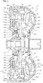
- FIG. 1 is a schematic configuration diagram showing a starting device 1 including a vibration damping device 20 of the present disclosure.
- the starting device 1 shown in the figure is mounted on a vehicle equipped with an engine (internal combustion engine) EG serving as a driving device, and is for transmitting power from the engine EG to a drive shaft DS of the vehicle, for example.
- an engine internal combustion engine
- the starting device 1 includes: a front cover 3 serving as an input member coupled to a crank shaft of the engine EG; a pump impeller (input side fluid transmission element) 4 that is fixed to the front cover 3 and that rotates integrally with the front cover 3; a turbine runner (output side fluid transmission element) 5 that can rotate coaxially with the pump impeller 4; a damper hub 7 serving as an output member fixed to an input shaft IS of a transmission (power transmission device) TM that is an automatic transmission (AT), a continuously variable transmission (CVT), a dual clutch transmission (DCT), a hybrid transmission or a deceleration device; a lockup clutch 8; and a damper device 10, and the like.
- a transmission power transmission device
- TM that is an automatic transmission (AT), a continuously variable transmission (CVT), a dual clutch transmission (DCT), a hybrid transmission or a deceleration device
- a lockup clutch 8 and a damper device 10, and the like.
- an "axial direction” basically indicates an extending direction of a central axis (axial center) of the starting device 1 and the damper device 10 (vibration damping device 20).
- a "radial direction” is basically indicates the radial direction of the starting device 1, the damper device 10, a rotation element of the damper device 10 and the like, that is, the linear extending direction that extends from the central axis of the starting device 1 and the damper device 10 in a direction (radial direction) orthogonal to the central axis.
- a “circumferential direction” basically indicates a circumferential direction of the starting device 1, the damper device 10, and the rotation element of the damper device 10, that is, a direction along a rotating direction of the rotation element.
- the pump impeller 4 has a pump shell 40 tightly fixed to the front cover 3 and a plurality of pump blades 41 arranged on an inner surface of the pump shell 40.
- the turbine runner 5 has a turbine shell 50 and a plurality of turbine blades 51 arranged on an inner surface of the turbine shell 50.
- An inner peripheral portion of the turbine shell 50 is fixed to the damper hub 7 via a plurality of rivets.
- the pump impeller 4 and the turbine runner 5 face each other, and a stator 6 for rectifying the flow of working oil (working fluid) from the turbine runner 5 to the pump impeller 4 is coaxially disposed therebetween.
- the stator 6 has a plurality of stator blades 60, and the rotation direction of the stator 6 is set to only one direction by a one-way clutch 61.
- the pump impeller 4, the turbine runner 5, and the stator 6 form a torus (annular flow path) for circulating working oil, and function as a torque converter (fluid transmission device) having a torque amplification function.
- the stator 6 and the one-way clutch 61 may be omitted, and the pump impeller 4 and the turbine runner 5 may function as a fluid coupling.
- the lockup clutch 8 is configured as a hydraulic multi-plate clutch, and executes lockup of the front cover 3 and the damper hub 7, that is, the input shaft IS of the transmission TM, via the damper device 10 and also releases the lockup.
- the lockup clutch 8 includes: a lockup piston 80 that is supported so as to be movable in an axial direction by a center piece 3s fixed to the front cover 3; a clutch drum 110 included in a drive member 11 that is an input element of the damper device 10; an annular clutch hub 82 fixed to an inner surface of the front cover 3 so as to face the lockup piston 80; a plurality of first friction engagement plates (friction plates having a friction material on both surfaces) 83 fitted to splines formed on the clutch drum 110; and a plurality of second friction engagement plates (separator plates) 84 fitted to splines formed on an outer peripheral surface of the clutch hub 82.
- the lockup clutch 8 includes: an annular flange member (oil chamber defining member) 85 that is attached to the center piece 3s of the front cover 3 so as to be positioned on an opposite side of the front cover 3 with respect to the lockup piston 80 as a reference, that is, on the turbine runner 5 side of the lockup piston 80; and a plurality of return springs 86 disposed between the front cover 3 and the lockup piston 80.
- the lockup piston 80 and the flange member 85 define an engagement oil chamber 87, and working oil (engagement hydraulic pressure) is supplied from a hydraulic control device (not shown) to the engagement oil chamber 87.
- the lockup clutch 8 may be configured as a hydraulic single plate clutch.
- the damper device 10 includes as rotation elements, a drive member (input element) 11 including the clutch drum 110, an intermediate member (intermediate element) 12, and a driven member (output element) 15 that is fixed to the damper hub 7 via a plurality of rivets along with the inner peripheral portion of the turbine shell 50.
- the damper device 10 includes as torque transmitting elements, a plurality of (for example, three in the present embodiment) first springs (first elastic bodies) SP1 and second springs (second elastic bodies) SP2 arranged alternately on the same circumference at intervals in the circumferential direction.
- first and second springs SP1, SP2 an arc coil spring made of a metal material wound so as to have an axial center extending in an arc shape when no load is applied, or a straight coil spring made of a metal material wound in a spiral shape so as to have an axial center extending straight when no load is applied is adopted. Further, as the first and second springs SP1, SP2, so-called double springs may be adopted.
- the drive member 11 of the damper device 10 includes the clutch drum 110 described above and an annular drive plate 111 coupled to the clutch drum 110 so as to rotate integrally with the clutch drum 110 via a plurality of rivets.
- the clutch drum 110 includes: a tubular drum portion 110a including a spline into which the plurality of first friction engagement plates 83 are fitted; an annular coupling portion 110b extending radially outward from one end of the drum portion 110a; a plurality of (for example, three at 120° intervals in the present embodiment) spring contact portions 110c that extends radially outward from the coupling portion 110b at intervals (at equal intervals) in the circumferential direction and that have claw portions in the axial direction; and a plurality of spring support portions 110d extending so as to be positioned radially outward of the drum portion 110a from the coupling portion 110b between each of the adjacent spring contact portions 110c in the circumferential direction.
- the drive plate 111 has a short tubular inner peripheral portion 111a and a support portion 111b that is offset in the axial direction from the outer peripheral portion of the drive plate 111 and that extends radially outward.
- the drive plate 111 is fixed to the coupling portion 110b of the clutch drum 110 via a plurality of rivets so as to face the coupling portion 110b at an interval in the axial direction.
- An intermediate member 12 is configured as an annular member that surrounds the first and second springs SP1, SP2 from the outside and that can (alternately) support the first and second springs SP1, SP2 together with the plurality of spring support portions 110d of the clutch drum 110 (drive member 11) while having the first and second springs SP1, SP2 adjacent to each other on the same circumference.
- the intermediate member 12 includes a plurality of spring contact portions 12ca (for example, three at 120° intervals in the present embodiment) extending radially inward from the outer peripheral portion at intervals in the circumferential direction, and a plurality of (for example, three at 120° intervals in the present embodiment) spring contact portions 12cb extending from a side portion in the axial direction.
- the inner peripheral portion of the intermediate member 12 is rotatably supported by an outer peripheral surface of the drive plate 111, and is supported in the axial direction by the support portion 111b.
- a driven member 15 includes an annular first driven plate 16, an annular second driven plate 17, and an annular third driven plate 18 that is coupled so as to rotate integrally with the first and second driven plates 16, 17 via a plurality of rivets and that is fixed to the damper hub 7 via the plurality of rivets.
- the second driven plate 17 is disposed closer to the front cover 3 than the first driven plate 16, and the third driven plate 18 is disposed closer to the turbine runner 5 than the second driven plate 17.
- the thickness of the second and third driven plates 17, 18 are set to be the same as each other.
- the first driven plate 16 includes an annular coupling portion 16a, a short cylindrical portion 16b extending axially from an outer circumference of the coupling portion 16a, and a plurality of (for example, three at 120° intervals in the present embodiment) spring contact portions 16c extended radially outward from an end portion of the cylindrical portion 16b and having a claw portion extending in the axial direction.
- the second driven plate 17 is an annular plate body, and an outer peripheral portion thereof is offset from an inner peripheral portion in the axial direction so as to be close to the third driven plate 18.
- the third driven plate 18 includes an annular coupling portion 18a that is coupled to the second driven plate 17 and the damper hub 7, a short cylindrical portion 18b that extends from an outer circumference of the coupling portion 18a in the axial direction so as to be spaced away from the second driven plate 17, and an annular portion 18c that is extended radially outward from an end portion of the cylindrical portion 18b and that faces the second driven plate 17 at an interval in the axial direction.
- the cylindrical portion 16b of the first driven plate 16 rotatably supports the drive plate 111 of the drive member 11. As a result, the drive member 11 and the intermediate member 12 supported by the drive plate 111 are aligned with the damper hub 7 by the driven member 15.
- the first and second springs SP1, SP2 are supported by a spring support portion 11d of the drive member 11 and the intermediate member 12 so as to be alternately arranged along the circumferential direction of the damper device 10, and one of each of the first and second springs SP1, SP2 is disposed between the spring contact portions 110c, which are adjacent to each other, of the drive member 11 (clutch drum 110).
- the first and second springs SP1, SP2 are arranged in an outer peripheral side region of the fluid chamber 9 so as to be positioned radially outward of the lockup clutch 8 (the lockup piston 80 and the first and second friction engagement plates 83, 84).
- each spring contact portion 12ca of the intermediate member 12 is in contact with end portions of the first and second springs SP1, SP2 that are disposed between the spring contact portions 110c adjacent to each other and that are paired (act in series), between the first and second springs SP1, SP2.
- each spring contact portion 12cb of the intermediate member 12 is in contact with end portions of the first and second springs SP1, SP2 that are disposed between the spring contact portions 110c adjacent to each other and that are paired (act in series), between the first and second springs SP1, SP2.
- each first spring SP1 is in contact with the corresponding spring contact portion 110c of the drive member 11, and the other end portion of each first spring SP1 is in contact with the corresponding spring contact portions 12ca, 12cb of the intermediate member 12.
- one end portion of each second spring SP2 is in contact with the corresponding spring contact portions 12ca, 12cb of the intermediate member 12, and the other end portion of each second spring SP2 is in contact with the corresponding spring contact portion 110c of the drive member 11.
- Each spring contact portion 16c of the driven member 15 (first driven plate 16) is interposed between the clutch drum 110 (spring contact portion 110c) and the drive plate 111, and in the mounted state of the damper device 10, similar to the spring contact portion 110c of the drive member 11, each spring contact portion 16c is in contact with the end portions of the first and second springs SP1, SP2, which do not form a pair (do not act in series), between the first and second springs SP1, SP2.
- the one end portion of each first spring SP1 is also in contact with the corresponding spring contact portion 16c of the driven member 15, and the other end portion of each second spring SP2 is also in contact with the corresponding spring contact portion 16c the driven member 15.
- the driven member 15 is coupled to the drive member 11 via the plurality of first springs SP1, the intermediate member 12, and the plurality of second springs SP2, and the first and second springs SP1, SP2 that are paired with each other are coupled in series via the spring contact portions 12ca, 12cb of the intermediate member 12, between the drive member 11 and the driven member 15.
- the distance between the axial center of the starting device 1 and the damper device 10 and the axial center of each first spring SP1 and the distance between the axial center of the starting device 1, etc. and the axial center of each second spring SP2 are the same.
- the damper device 10 of the present embodiment includes a first stopper that restricts the relative rotation of the drive member 11 and the intermediate member 12 and deflection of the first spring SP1, and a second stopper that restricts the relative rotation of the drive member 11 and the driven member 15 (both the first stopper and the second stopper are not shown).
- the first stopper is configured to restrict the relative rotation of the drive member 11 and the intermediate member 12 at the stage in which a torque transmitted from the engine EG to the drive member 11 reaches a predetermined torque (first threshold value) T1 that is smaller than a torque T2 (second threshold value) corresponding to a maximum torsion angle of the damper device 10.
- the second stopper is configured to restrict the relative rotation of the drive member 11 and the driven member 15 at the stage in which the torque transmitted to the drive plate 11 reaches the torque T2 corresponding to the maximum torsion angle.
- the damper device 10 has a two-step (two-stage) damping characteristic.
- the first stopper may be configured to restrict the relative rotation of the intermediate member 12 and the driven member 15 and deflection of the second spring SP2.
- the damper device 10 may include a stopper that restricts the relative rotation of the drive member 11 and the intermediate member 12 and deflection of the first spring SP1, and a stopper that restricts the relative rotation of the intermediate member 12 and the driven member 15 and deflection of the second spring SP2.
- the vibration damping device 20 is connected to the driven member 15 of the damper device 10 and is disposed inside the fluid chamber 9 filled with working oil.
- the vibration damping device 20 includes the second and third driven plates 17, 18 serving as supporting members (supporting plates), a plurality of (for example, three in the present embodiment) weight bodies 22 serving as restoring force generation members coupled to the second and third driven plates 17, 18 so as to transmit and receive torque to and from the second and third driven plates 17, 18, and one annular inertia mass body 23 that is coupled to each weight body 22.
- the second driven plate 17 has a plurality of (for example, three in the present embodiment) protruding portions 172 that is formed so as to protrude radially outward from an outer peripheral surface 171 of the second driven plate 17 at intervals (equal intervals) in the circumferential direction.
- Each protruding portion 172 is formed with one slit (opening portion) 173 extending in the radial direction of the second driven plate 17.
- Each slit 173 has a pair of flat inner surfaces 174 that extend in the radial direction of the second driven plate 17 and that face each other at intervals in the circumferential direction of the second driven plate 17.
- the pair of inner surfaces 174 each functions as a torque transmission surface for transmitting and receiving torque to and from the weight body 22.
- the slit 173 is formed so that an end portion on a radial outer side is opened.
- the slit 173 may be formed so that the end portion on the radial outer side is not opened.
- the third driven plate 18 has a plurality of (for example, three in the present embodiment) protruding portions 182 that is formed so as to protrude radially outward from an outer peripheral surface of the third driven plate 18 at intervals (equal intervals) in the circumferential direction.
- Each protruding portion 182 is formed with one slit (opening portion) 183 extending in the radial direction of the third driven plate 18.
- Each slit 183 has a pair of flat inner surfaces 184 that extend in the radial direction of the third driven plate 18 and that face each other at intervals in the circumferential direction of the third driven plate 18.
- the pair of inner surfaces 184 each functions as a torque transmission surface for transmitting and receiving torque to and from the weight body 22.
- the slit 183 is formed so that an end portion on a radial outer side is opened.
- the slit 183 may be formed so that the end portion on the radial outer side is not opened.
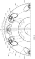
- each weight body 22 has two plate members (mass bodies) 220 having the same shape as each other, one first coupling shaft 221, and two second coupling shafts 222.
- each plate member 220 is formed by a metal plate so as to have a symmetrical and arcuate planar shape, and the two plate members 220 are coupled to each other so as to face each other at an interval in the axial direction of the second and third driven plates 17, 18 via one first coupling shaft 221 and two second coupling shafts 222.
- each plate member 220 has an outer peripheral surface formed by a cylindrical surface CSo and an inner peripheral surface having a concave curved surface.
- each plate member 220 includes: a protruding portion 220a protruding in a direction away from the outer peripheral surface at a central portion of the plate member 220 in a width direction near the first coupling shaft 221, that is, near the first coupling shaft 221; and two protruding portions 220b that each protrude in a direction away from the outer peripheral surface at one end portion or the other end portion of the plate member 220.
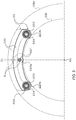
- the protruding portions 220a, 220b both have a cylindrical surface, and the surfaces of the protruding portions 220a, 220b are in contact with a cylindrical surface CSi as shown in FIG. 5 .
- the first coupling shaft 221 is formed in the shape of a solid (or hollow) round bar, and as shown in FIGS. 3 and 5 , the first coupling shaft 221 is fixed (coupled) to the two plate members 220 so that the shaft center of the coupling shaft 221 passes through a center of gravity G of the weight body 22 (plate member 220) on a center line CL (a straight line that passes through the rotation center RC of the second and third driven plates 17, 18 in the mounted state of the weight body 22) in the width direction (circumferential direction) of the weight body 22.
- the first coupling shaft 221 has an outer diameter shorter than an interval between the pair of inner surfaces 174, 184 of the second and third driven plates 17, 18 (widths of the slits 173, 183) and a radial length of the inner surfaces 174, 184.
- the first coupling shaft 221 is slidably disposed in the slit 173 of each protruding portion 172 of the second driven plate 17 so as to be in contact with either one of the pair of inner surfaces 174, and is slidably disposed in the slit 183 of each of the protruding portions 182 of the third driven plate 18 so as to be in contact with either one of the pair of inner surfaces 184.
- each weight body 22 is coupled to the second and third driven plates 17, 18 serving as supporting members so as to be movable in the radial direction, and form a sliding pair with the second and third driven plates 17, 18.
- the first coupling shaft 221 can come into contact with either one of the inner surfaces 174 of the corresponding slit 173 and the inner surfaces 184 of the corresponding slit 183 and thus, the first coupling shaft 221 functions as a torque transmission portion that transmits and receives torque to and from the second and third driven plates 17, 18.
- the first coupling shaft 221 may rotatably support a cylindrical outer ring via a plurality of rollers or balls (rolling bodies), or may rotatably support the outer ring without interposing a rolling element.
- each weight body 22 is formed in the shape of a solid (or hollow) round bar, and as shown in FIG. 3 , the weight body 22 (plate member 220) is fixed to one end portion or the other end portion of the two plate members 220 so as to be positioned symmetrically with respect to the center line CL of the weight body 22 (plate member 220) that passes through the center of gravity G described above. That is, the shaft centers of the two second coupling shafts 222 fixed to the two plate members 220 are positioned symmetrically with respect to the center line CL in the width direction of the weight body 22. Further, as shown in FIGS.
- the second coupling shaft 222 rotatably supports a cylindrical outer ring (roller) 224 via a plurality of rollers (rolling elements) 223, and the second coupling shaft 222, the plurality of rollers 223, and the outer ring 224 configure a guided portion 225 of the weight body 22.
- the protruding portion 220b is formed on both end portions of each plate member 220, the outer periphery of the outer ring 224 does not protrude outward of a peripheral edge portion of the plate member 220.
- a plurality of balls may be arranged in place of the plurality of rollers 223 between the second coupling shaft 222 and the outer ring 224, or the rollers and balls may be omitted.
- the inertia mass body 23 includes one annular first plate member 231 formed of a metal plate and two annular second plate members 232 formed of a metal plate, and an annular second plate member 232 formed of a metal plate.
- the weight of the inertia mass body 23 (first and second plate members 231, 232) is set to be sufficiently heavier than the weight of one weight body 22.
- the curvature radius of an outer peripheral surface of the first plate member 231 and the curvature radius of an outer peripheral surface of each second plate member 232 are set to be the same. Further, as shown in FIGS.
- each second plate member 232 is formed to be positioned radially outward of an inner peripheral surface of the first plate member 231, when the second plate member 232 is disposed coaxially with the first plate member 231. Further, as shown in FIGS. 4 and 6 , the thickness of each second plate member 232 is set to be less than the thickness of the second and third driven plates 17, 18 (protruding portions 172, 182).
- the first plate members 231 has a plurality of (for example, six in the present embodiment) guide portions 235 arranged at intervals in the circumferential direction so as to be in pairs in two by two.
- Each guide portion 235 is an opening portion extending in a bow shape, and guides the guided portion 225 of each corresponding weight body 22.
- the two paired guide portions 235 are formed to be symmetrical with respect to a straight line extending in the radial direction so as to divide the first plate member 231 into thirds around the center (a straight line that equally divides the first plate member 231 and the like into the number of weight bodies 22).
- each guide portion 235 includes a guide surface 236 having a concave curved surface shape and that is a rolling surface of the outer ring 224 configuring the guided portion 225 of the weight body 22, a supporting surface 237 having a convex curved surface shape and that faces the guide surface 236 on the inner peripheral side of the first plate member 231, etc. (on the center side of the first plate member 231, etc.) than the guide surface 236, and two stopper surfaces 238 continuous with both the guide surface 236 and the supporting surface 237 on both sides thereof.
- the guide surface 236 is formed so as to swing around a virtual axis 24 so that the center of gravity G of the weight body 22 swings with respect to (approaches and moves away from) a rotation center RC of the second and third driven plates 17, 18 along the radial direction, while changing an inter-axial distance L1 between the virtual axis 24 that is set so that the relative position with respect to the inertia mass body 23 is constant, by having the outer ring 224 roll on the guide surface 236 in accordance with the rotation of the second and third driven plates 17, 18.
- the virtual axis 24 is a point on a straight line that divides the first plate member 231, etc. into thirds around the center and that extends in the radial direction (a straight line that equally divides the first plate member 231, etc. by the number of weight bodies 22), and is a straight line orthogonal to the first plate member 231, etc. and passes through a point spaced away from the center (rotation center RC) of the first plate member 231, etc. by a predetermined fixed inter-axial distance L2.
- the supporting surface 237 is a convex surface formed so as to face the guide surface 236 at an interval set to be slightly larger than the outer diameter of the outer ring 224
- the stopper surface 238 is a concave surface extending in an arc shape, for example.
- the plurality of guide surfaces 236 are formed at intervals in the circumferential direction so as to be continuous with the guide surface 236 of each guide portion 235 of the first plate member 231.
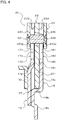
- the second and third driven plates 17, 18 serving as supporting members are disposed in the axial direction between the two plate members 220 configuring the weight body 22. Further, the second driven plate 17 and the annular portion 18c of the third driven plate 18 face each other at an interval in the axial direction as described above, and the first plate member 231 of the inertia mass body 23 is disposed between the second driven plate 17 and the annular portion 18c of the third driven plate 18 in the axial direction.
- the inner peripheral surface of the first plate member 231 is rotatably supported by the outer peripheral surface of the cylindrical portion 18b of the third driven plate 18.
- the inertia mass body 23 is rotatably supported with respect to the damper hub 7 by the driven member 15 so as to be rotatably supported around the rotation center RC by the second and third driven plates 17, 18 and thus, the second and third driven plates 17, 18 form a rotation pair.
- each second plate member 232 of the inertia mass body 23 is fixed to the surface of the first plate member 231 via a fixing tool not shown so that each second plate member 232 of the inertia mass body 23 is disposed between the two plate members 220 of the weight body 22 and so as to be positioned on the corresponding one radial outer side of the second and third driven plates 17, 18 (protruding portions 172, 182).
- the two plate members 220 of the weight body 22 are coupled to each other by the first and second coupling shafts 221, 222 so as to sandwich the second and third driven plates 17, 18 (protruding portions 172, 182) and the inertia mass body 23 from both sides in the axial direction.
- the first plate member 231 of the inertia mass body 23 on the first plate member 231 of the inertia mass body 23, an opening portion 239 extending in an arc shape is formed, and the first coupling shaft 221 of the weight body 22 is inserted in the opening portion 239.
- the inner surface of the opening portion 239 is formed so as not to come into contact with the first coupling shaft 221. Further, as shown in FIG.
- each second coupling shaft 222 coupling the two plate members 220 passes through the corresponding guide portion 23 5 of the inertia mass body 23 (first plate member 231), and each outer ring 224 is in contact with the guide surface 236 of the corresponding guide portion 235.
- the weight body 22 and the second and third driven plates 17, 18 form a sliding pair
- the second and third driven plates 17, 18 and the inertia mass body 23 form a rotating pair.
- the outer ring 224 of each weight body 22 can roll on the guide surface 236 of the corresponding guide portion 235
- each weight body 22 and the inertia mass body 23 form a sliding pair.
- the second and third driven plates 17, 18, the plurality of weight bodies 22, and the inertia mass body 23 of the guide portion 235 configure the slider crank mechanism (double slider crank chain).
- the equilibrium state of the vibration damping device 20 is a state in which the center of gravity G of each weight body 22 is positioned on a straight line passing through the corresponding virtual axis 24 and the rotation center RC, that is, on the center line CL (see FIG. 3 ).
- the plate member 220 of each weight body 22 and the inertia mass body 23 are disposed so as to be offset in the axial direction of the second and third driven plates 17, 18 serving as supporting members and the second and third driven plates 17, 18 are disposed between the plate member 220 of each weight body 22 and the inertia mass body 23.
- the second driven plate 17 (protruding portion 172) is disposed between one plate member 220 of each weight body 22 and the first plate member 231 of the inertia mass body 23 in the axial direction
- the third driven plate 18 (protruding portion 182) is disposed between the other plate member 220 of each weight body 22 and the first plate member 231 of the inertia mass body 23 in the axial direction.
- each weight body and inertia mass body 23 are at least partially overlapped in the radial direction with the first and second springs SP1, SP2 of the damper device 10 when seen from the axial direction (turbine runner 5 side).
- each plate member 220 of the weight body 22 is in contact with the surface of the protruding portion 172 of the second driven plate 17 or the surface of the protruding portion 182 of the third driven plate 18 and thus, at least one protrusion (dowel) 220p that restricts the axial movement of the plate member 220 with respect to the second and third driven plates 17, 18 is formed.
- a plurality of protrusions (dowels) 17p that is in contact with one surface of the first plate member 231 of the inertia mass body 23 and that restrict axial movement of the inertia mass body 23 is formed at intervals in the circumferential direction.
- a plurality of protrusions (dowels) 18p that is in contact with the other surface of the first plate member 231 of the inertia mass body 23 and that restrict axial movement of the inertia mass body 23 is formed at intervals in the circumferential direction.
- protrusions that are in sliding contact with each plate member 220 of the weight body 22 may be formed.
- protrusions that are in sliding contact with the second and third driven plates 17, 18, may be formed.
- the operation of the starting device 1 including the vibration damping device 20 will be described.
- the torque (power) from the engine EG serving as the motor is transmitted to the input shaft IS of the transmission TM via a path of the front cover 3, the pump impeller 4, the turbine runner 5, and the damper hub 7.
- the torque (power) from the engine EG is transmitted to the input shaft IS of the transmission TM via a path of the front cover 3, the lockup clutch 8, the drive member 11, the first spring SP1, the intermediate member 12, the second spring SP2, the driven member 15, and the damper hub 7.
- the first and second springs SP1, SP2 acts in series via the intermediate member 12 between the drive member 11 and the driven member 15 until the torque transmitted to the drive member 11 reaches the torque T1.
- the torque from the engine EG transmitted to the front cover 3 is transmitted to the input shaft IS of the transmission TM, and the fluctuation of the torque from the engine EG is dampened (absorbed) by the first and second springs SP1, SP2 of the damper device 10.
- the torque transmitted to the drive member 11 is equal to or more than the torque T1
- the fluctuation of the torque from the engine EG is damped (absorbed) by the first spring SP1 of the damper device 10 until the torque reaches the torque T2.
- the second and third driven plates 17, 18 (driven member 15) of the damper device 10 also rotates around the shaft center of the starting device 1 in the same direction as the front cover 3.
- the first coupling shaft 221 of each weight body 22 is in contact with either one of the pair of inner surfaces 174, 184 of the corresponding slits 173, 183 in accordance with the rotation direction of the second and third driven plates 17, 18.
- the outer ring 224 supported by the second coupling shaft 222 of the weight body 22 is pressed against the guide surface 236 of the corresponding guide portion 235 of the inertia mass body 23 due to the application of the centrifugal force on the weight body 22, and one end portion of the guide portion 235 rolls on the guide surface 236 by receiving the force of the moment of inertia (rotational difficulty) of the inertia mass body 23.
- each weight body 22 (center of gravity G) approaches the rotation center RC along the radial direction of the second and third driven plates 17, 18 while each weight body 22 is guided by the two (a pair of) guided portion 225 (the outer ring 224 and the second coupling shaft 222) and two (a pair of) guide portions 235 and the rotation of each weight body 22 is restricted.
- each weight body 22 rotates while changing the inter-axial distance L1 around the virtual axis 24 serving as the swinging center, and accordingly, the inertia mass body 23 relatively rotates around the rotation center RC in the reverse direction with respect to the second and third driven plates 17, 18.
- a component force of the centrifugal force acting on the center of gravity G of each weight body 22 is transmitted to the inertia mass body 23 via the guided portion 225 (outer ring 224) and the guide surface 236 of the guide portion 235, and becomes a restoring force that tries to return the inertia mass body 23 to the position in the equilibrium state.
- the restoring force overcomes the force (moment of inertia) that tries to make the inertia mass body 23 rotate in the rotation direction the same as before.
- each weight body 22 is guided by the pair of guided portions 225 and the pair of guide portions 235, and is moved in the direction opposite to the direction before so as to be spaced away from the rotation center RC along the radial direction of the second and third driven plates 17, 18 while being restricted from rotating. Further, the inertia mass body 23 rotates around the rotation center RC in the direction opposite to the direction before toward the position in the equilibrium state while being interlocked with each weight body 22 by the application of the restoring force from each weight body 22, that is, the component force of the centrifugal force described above.
- the inertia mass body 23 When the inertia mass body 23 reaches the position in the equilibrium state while the second and third driven plates 17, 18 rotate in one direction described above, the inertia mass body 23 tries to further rotate in the same direction due to the moment of inertia (difficulty of stopping). Further, the outer ring 224 of the weight body 22 receives a force due to the moment of inertia (difficulty of stopping) of the inertia mass body 23 and rolls on the guide surface 236 toward the other end portion of the guide portion 235.
- each weight body 22 (center of gravity G) is guided by the pair of guided portions 225 and the pair of guide portions 235, and approaches the rotation center RC again, along the radial direction of the second and third driven plates 17, 18 while being restricted from rotating. Further, since the guided portion 225 is guided by the guide portion 235, the center of gravity G of each weight body 22 rotates while changing the inter-axial distance L1 around the virtual axis 24 serving as the swinging center, and accordingly, the inertia mass body 23 relatively rotates around the rotation center RC in the same direction with respect to the second and third driven plates 17, 18.
- each weight body 22 is transmitted as the restoring force described above to the inertia mass body 23 via the guided portion 225 and the guide surface 236 of the guide portion 235, and overcomes the force (moment of inertia) that tries to make the inertia mass body 23 rotate in the rotation direction the same as before, at the end portion in the swinging range.
- each weight body 22 is guided by the pair of guided portions 225 and the pair of guide portions 235, and is moved so as to be spaced away from the rotation center RC along the radial direction of the second and third driven plates 17, 18 while being restricted from rotating.
- the inertia mass body 23 rotates around the rotation center RC toward the position in the equilibrium state while being interlocked with each weight body 22 by the application of the restoring force from each weight body 22, that is, the component force of the centrifugal force described above.
- each weight body 22 serving as a restoring force generation member of the vibration damping device 20 swings (performs reciprocating motion) with respect to the rotation center RC along the radial direction of the second and third driven plates 17, 18 in the swinging range centered around the position in the equilibrium state that is set in accordance with the amplitude (vibration level) of the vibration transmitted from the engine EG to the driven member 15.
- the component force of the centrifugal force acting on each weight body 22 is transmitted as a restoring force to the inertia mass body 23 via the guided portion 225 and the guide portion 235, and the inertia mass body 23 swings (performs reciprocating rotary motion) in the opposite direction of the second and third driven plates 17, 18 around the rotation center RC in the swinging range centered around the position in the equilibrium state that is set in accordance with the swinging range of each weight body 22.
- a torque (inertial torque) having a phase opposite to a fluctuating torque (vibration) transmitted from the engine EG to the drive member 11 from the swinging inertia mass body 23 can be applied to the second and third driven plates 17, 18 via each guide portion 235, the guided portion 225, and each weight body 22, the first coupling shaft 221, and the protruding portions 172, 182.
- the vibration damping device 20 by setting the specifications of the vibration damping device 20 so as to have an order in accordance with an order of vibration transmitted from the engine EG to the second and third driven plates 17, 18 (excitation order: a 1.5th order when the engine EG is a 3-cylinder engine, and a second order when the engine EG is a 4-cylinder engine), it is possible to satisfactorily dampen the vibration transmitted from the engine EG to the driven member 15 (second and third driven plates 17, 18) by the vibration damping device 20 regardless of the rotation speed of the engine EG (second and third driven plates 17, 18).
- the vibration damping device 20 it is possible to restrict rotation of each weight body 22 by the pair of guided portions 225 and the pair of guide portions 235, and suppress a decrease in the order of the vibration damping device 20 resulting from an increase in the equivalent mass due to the rotation of the weight body 22. Further, it is possible to suppress damping of the centrifugal force (the component force thereof) acting on the weight body 22 used as the restoring force for swinging the inertia mass body 23 by smoothing swinging the weight body 22 with respect to the second and third driven plates 17, 18. In addition, by suppressing the decrease of the order resulting from the rotation of the weight body 22, it is possible to sufficiently secure the weight of the inertia mass body 23 and satisfactorily obtain a vibration damping effect.
- each weight body 22 by defining (constraining) the movement of each weight body 22 by the pair of guided portions 225 and the pair of guide portions 235, it is possible to decrease the frictional force between the first coupling shaft 221 and the protruding portions 172, 182 of the second and third driven plates 17, 18 when torque is transmitted and received between each weight body 22 and the second and third driven plates 17, 18.
- each weight body 22 the two guided portions 225 are arranged symmetrically with respect to the center line CL in the width direction of the plate member 220, and the first coupling shaft 221 serving as the torque transmission portion is installed on the center line CL.
- the weight body 22 can be swung more smoothly while the rotation is restricted by the pair of guide portions 235 and the pair of guided portions 225, and the frictional force generated between the first coupling shaft 221 and the protruding portions 172, 182 can be reduced to satisfactorily suppress the centrifugal force acting on the weight body 22 from being dampened.
- the guided portion 225 is provided on the weight body 22, and the guide portion 235 is formed on the inertia mass body 23.
- the centrifugal force acting on the weight body 22 by moving the center of gravity G of the weight body 22 from the rotation center RC that is, the restoring force acting on the inertia mass body 23 can be suppressed from decreasing, and the vibration damping performance can be satisfactorily ensured.
- the guide portion 235 may be provided on the weight body 22, and the guided portion 225 may be formed on the inertia mass body 23.
- the present inventors carried out intensive research to further improve the vibration damping performance of the vibration damping device 20 including the weight body 22 that swings in the radial direction of the driven member 15 in accordance with the rotation of the driven member 15 and the inertia mass body 23 that swings around the rotation center RC in conjunction with the weight body 22, and focused on the relationship between the axial length L1 between the center of gravity G of the weight body 22 and the virtual axis 24 that is the swing center of the weight body 22 and the inter-axial distance L2 between the virtual axis 24 and the rotation center RC of the driven member 15.
- the vibration damping device of Patent Document 1 the sum of a distance L3 between the center of gravity of each weight body and the swing center of the weight body and a distance L4 between the swing center of the weight body and the rotation center (L3 + L4) is constant. It is considered that the distances L3 and L4 (the ratio of the two) are set so that when the amplitude of the inertia mass body (the swing angle around the rotation center of the inertia mass body proportional to the swing angle of the weight body) is large, the deviation of the order of the vibration damping device is small and isochronism is satisfactorily ensured.
- the present inventors performed various analyses in which while the sum of the inter-axial distances L1, L2 is constant, the ratio of the two is changed, and the inter-axial distance L1 is varied.
- the present inventors found out, as a result, that the vibration damping device 20 including the weight body 22 that swings in the radial direction of the driven member 15 and the inertia mass body 23 that swings around the rotation center RC in conjunction with the weight body 22 has the characteristics (1) to (6) below.
- the vibration damping device 20 of the present disclosure is configured so that the inter-axial distance L1 between the center of gravity G of the weight body 22 and the virtual axis 24 serving as the swing center changed in accordance with the change in the swing angle ⁇ (the swing angle of the inertia mass body 23 around the rotation center RC) of the weight body 22 with respect to the inertia mass body 23.
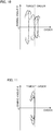
- the order of the vibration damping device 20 when the swing angle ⁇ is zero is increased and the order is increased as the swing angle ⁇ is increased.
- the order of the vibration damping device 20 when the swing angle ⁇ of the weight body 22 with respect to the inertia mass body 23 is zero can be decreased to return to the order before the inter-axial distance L1 was decreased. As shown in FIG.
- the order of the vibration damping device 20 can be matched with the target order while the deviation of the order in accordance with the increase of the swing angle ⁇ is suppressed, and the torque (inertial torque) applied to the driven member 15 from the inertia mass body 23 can be increased.
- the torque inertial torque
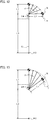
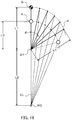
- the shape of the guide surface 236 of each guide portion 235 of the inertia mass body 23 can be determined as follows. That is, after swing trajectory P (see FIG. 12 ) of the center of gravity G is set by analysis and the like so that the inter-axial distance L1 between the center of gravity G and the virtual axis 24 (swing center) is increased as the swing angle ⁇ of the weight body 22 is increased, the center of gravity G of the weight body 22 is positioned on the swing trajectory P, the two outer rings 224 (guided portions 225) are disposed symmetrically with respect to the center line CL, and a line segment connecting the axial centers of the two outer rings 224 are defined.
- the center of gravity G of the weight body 22 is rotated around the virtual axis 24 by a minute constant angle so as to move along the swing trajectory P and the two outer rings 224 are move so that the line segment connecting the shaft centers of the two outer rings 224 to each other is orthogonal to the center line CL while maintaining the positional relationship with the center of gravity G.
- the guide surface 236 of the guide portion 235 as shown by a solid line in FIG. 3 can be obtained.
- the shapes of the supporting surface 237 and the stopper surface 238 can be arbitrarily determined in consideration of the outer diameter of the outer ring 224.
- the order of the vibration damping device 20 when the swing angle ⁇ is zero is decreased and the order is increased as the swing angle ⁇ is decreased.
- the order of the vibration damping device 20 when the swing angle ⁇ of the weight body 22 with respect to the inertia mass body 23 is zero can be increased to return to the order before the inter-axial distance L1 was increased. As shown in FIG.
- the order of the vibration damping device 20 can be matched with the target order while the deviation of the order in accordance with the increase of the swing angle ⁇ is suppressed, and the torque (inertial torque) applied to the driven member 15 from the inertia mass body 23 can be decreased.
- the torque inertial torque
- the swing trajectory P of the center of gravity G of the weight body 22 is set by analysis and the like so that the inter-axial distance L1 between the center of gravity G and the virtual axis 24 (swing center) is increased as the swing angle ⁇ of the weight body 22 is increased, and the shape of the guide surface 236 (see the dotted line in FIG. 3 ) of each guide portion 235 of the inertia mass body 23 (first plate member 231) is set similarly to a case in which the inter-axial distance L1 between the center of gravity G and the virtual axis 24 (swing center) is increased as the swing angle ⁇ is increased.
- FIG. 14 is a front view showing another weight body 22B that can be applied to the vibration damping device 20 described above.
- the same elements as those of the vibration damping device 20 and the like described above are designated by the same reference numerals, and redundant description will be omitted.
- the weight body 22B shown in FIG. 14 includes the weight body 22 serving as a weight main body and a center of gravity adjusting weight 229 fixed to the weight body 22. Similar to the weight body described above, the weight body 22 includes the two plate members 220, and the first coupling shaft 221 that is fixed (coupled) to the two plate member 220 so that the shaft center A serving as a reference point passes through the center of gravity of the weight body 22 on the center line CL in the width direction (circumferential direction) of the weight body 22 (plate member 220).
- the center of gravity adjusting weight 229 is formed of metal, for example, and the center of gravity adjusting weight 229 is fixed to each plate member 220 so that the center of gravity G of the weight body 22B, which serves as the restoring force generation member including the weight body 22 and the center of gravity adjusting weight 229, is positioned radially inward of the shaft center A (reference point) of the first coupling shaft 221 on the center line CL that includes the virtual axis 24, which serves as the swing center, and the rotation center RC when the swing angle ⁇ of the weight body 22B with respect to the inertia mass body 23 is zero.
- the center of gravity of the weight body 22 before the center of gravity adjusting weight 229 is fixed that is, the shaft center A (reference point) of the first coupling shaft 221
- the shaft center A (reference point) of the first coupling shaft 221 is positioned radially outward of the center of gravity G of the weight body 22B on the center line CL when the swing angle ⁇ is zero.
- the inter-axial distance L1 between the center of gravity G of the weight body 22B and the virtual axis 24 is shorter than an inter-axial distance L0 between the shaft center A of the first coupling shaft 221 (the center of gravity of the weight body 22 before the center of gravity adjusting weight 229 is fixed) and the virtual axis 24, when the swing angle ⁇ of the weight body 22B with respect to the inertia mass body 23 is zero, as shown in FIG. 14 and FIG. 15 .
- the guide surface 236 of each guide portion 235 of the inertia mass body 23 (first plate member 231) is formed so that the outer ring 224 rolls on the guide surface 236 in accordance with the rotation of the second and third driven plates 17, 18 and thus, the shaft center A (the center of gravity of the weight body 22) of the first coupling shaft 221 swings with respect to (approaches and moves away from) the rotation center RC along the radial direction and swings around the virtual axis 24 while keeping the inter-axial distance L0 between the shaft center A and the virtual axis 24 constant (see the long dashed double short dashed line in FIG. 3 ).
- the vibration damping device 20 of the present disclosure even if the center of gravity adjusting weight 229 is fixed to the weight body 22 serving as a weight main body and the center of gravity G of the entirety of the weight body 22 and the center of gravity adjusting weight 229 (restoring force generation member) is moved radially inward on the center line CL, in the vibration damping device in which the center of gravity of the weight body 22 (the shaft center A of the first coupling shaft 221) swings around the virtual axis 24 while keeping the inter-axial distance L0 between the center of gravity and the virtual axis 24 (swing center) constant. Then, by applying the weight body 22B including the center of gravity adjusting weight 229 to the vibration damping device 20, it is possible to further improve the tunability of the vibration damping performance of the vibration damping device 20.
- the center of gravity adjusting weight 229 may be fixed to each plate member 220 so that when the swing angle ⁇ of the weight body 22 is zero, the center of gravity G of the weight body 22B, which serves as the restoring force generation member including the weight body 22B and the center of gravity adjusting weight 229, is positioned radially outward of the shaft center A (reference point) of the first coupling shaft 221 on the center line CL that includes the virtual axis 24, which serves as the swing center, and the rotation center RC.
- the center of gravity of the weight body 22 before the center of gravity adjusting weight 229 is fixed that is, the shaft center A (reference point) of the first coupling shaft 221
- the shaft center A (reference point) of the first coupling shaft 221 is positioned radially inward of the center of gravity G of the weight body 22B on the center line CL when the swing angle ⁇ of the weight body 22B is zero.
- the inter-axial distance L1 between the center of gravity G of the weight body 22B and the virtual axis 24 is longer than an inter-axial distance L0 between the shaft center A of the first coupling shaft 221 (the center of gravity of the weight body 22 before the center of gravity adjusting weight 229 is fixed) and the virtual axis 24, when the swing angle ⁇ of the weight body 22B with respect to the inertia mass body 23 is zero, as shown in FIG. 16 .
- the inter-axial distance L1 between the center of gravity G of the weight body 22B and the virtual axis 24 serving as the swing center is increased as the swing angle ⁇ (absolute value) is decreased from the state in which the swing angle ⁇ of the weight body 22B with respect to the inertia mass body 23 is zero, as shown in FIG. 16 .
- the center of gravity adjusting weight 229 may be fixed to the weight body 22 serving as a weight main body and the center of gravity of the entirety of the weight body 22 and the center of gravity adjusting weight 229 (restoring force generation member) may be moved radially outward on the center line CL described above, in the vibration damping device in which the center of gravity G of the weight body 22 (the shaft center A of the first coupling shaft 221) swings around the virtual axis 24 while keeping the inter-axial distance (L0) between the center of gravity and the virtual axis 24 (swing center) constant.
- the vibration damping device 20 of the present disclosure it is possible to obtain the vibration damping device 20 of the present disclosure and further improve the tunability of the vibration damping performance of the vibration damping device 20.
- the vibration damping device 20 of the present disclosure can be obtained, even when the center of gravity adjusting weight is not used, the reference point is set with respect to the weight body so as to be positioned radially outward or radially inward of the center of gravity G on the straight line including the virtual axis (swing center) and the rotation center RC when the swing angle ⁇ is zero, and the trajectory of the reference point is set so that the reference point swings around the virtual axis while keeping the distance between the reference point and the virtual axis constant.
- FIG. 17 is an enlarged view showing another vibration damping device 20X of the present disclosure.
- the same elements as those of the vibration damping device 20 and the like described above are designated by the same reference numerals, and redundant description will be omitted.
- the vibration damping device 20X is also connected to the driven member 15 of the damper device 10 and is disposed inside the fluid chamber 9 filled with working oil.
- the vibration damping device 20X includes the second and third driven plates 17, 18 serving as supporting members (supporting plates), a plurality of (for example, three in the present embodiment) weight bodies 22X serving as restoring force generation members coupled to the second and third driven plates 17, 18 so as to transmit and receive torque to and from the second and third driven plates 17, 18, one annular inertia mass body 23X that is coupled to each weight body 22X, and a plurality of (for example, six in the present embodiment) coupling members 25.
- each weight body 22X has two plate members (mass bodies) 220 having the same shape as each other, and one first coupling shaft 221X.
- Each plate member 220 is formed by a metal plate so as to have a symmetrical and arcuate planar shape, and the two plate members 220 are coupled to each other so as to face each other at an interval in the axial direction of the second and third driven plates 17, 18 via the first coupling shaft 221X.
- each plate member 220 has an outer peripheral surface and an inner peripheral surface each formed by a cylindrical surface.
- each plate member 220 has two first guide portions 225X disposed so as to be arranged at intervals in the width direction (circumferential direction). With respect to the plate member 220, the two first guide portions 225X are formed symmetrically with respect to the center line CL in the width direction of the plate member 220 passing through the center of gravity of the weight body 22X. Each first guide portion 225X is an opening portion extending in a bow shape, and as shown in FIG.
- first guide surface 226 that has a concave spherical surface shape recessed toward the rotation center RC side of the second and third driven plates 17, 18 (driven member 15) on the inner peripheral side of the plate member 220
- first supporting surface 227 that has a convex curved surface shape that is continuous with the first guide surface 226 and that faces the first guide surface 226 on the outer peripheral side of the plate member 220.
- the first guide surface 226 may be a concave curved surface that is recessed toward the opposite side of the rotation center RC, that is, toward the radial outer side
- the first supporting surface 227 may be a concave curved surface that faces the first guide surface 226.
- the coupling shaft 221X is formed in the shape of a solid (or hollow) round bar, and as shown in FIG. 17 , the coupling shaft 221X is fixed (coupled) to the two plate members 220 so that the shaft center of the coupling shaft 221 passes through the center of gravity G of the weight body 22X (plate member 220) on the center line CL (a straight line that passes through the rotation center RC of the second and third driven plates 17, 18 in the mounted state of the weight body 22X) in the width direction (circumferential direction) of the weight body 22X.
- the coupling shaft 221X has an outer diameter shorter than an interval between the pair of inner surfaces 174, 184 of the second and third driven plates 17, 18 (widths of the slits 173, 183) and a radial length of the inner surfaces 174, 184.
- the first coupling shaft 221X is slidably disposed in the slit 173 of each protruding portion 172 of the second driven plate 17 so as to be in contact with either one of the pair of inner surfaces 174, and is slidably disposed in the slit 183 of each of the protruding portions 182 of the third driven plate 18 so as to be in contact with either one of the pair of inner surfaces 184.
- each weight body 22X is coupled to the second and third driven plates 17, 18 serving as supporting members so as to be movable in the radial direction, and form a sliding pair with the second and third driven plates 17, 18.
- the coupling shaft 221X can come into contact with either one of the inner surfaces 174 of the corresponding slit 173 and the inner surfaces 184 of the corresponding slit 183 and thus, the first coupling shaft 221 functions as a torque transmission portion that transmits and receives torque to and from the second and third driven plates 17, 18.
- the coupling shaft 221X may rotatably support a cylindrical outer ring via a plurality of rollers or balls (rolling bodies), or may rotatably support the outer ring without interposing a rolling element.
- the inertia mass body 23X includes one annular first plate member 231 formed of a metal plate and two annular second plate members 232 each formed of a metal plate.
- the weight of the inertia mass body 23X (first and second plate members 231, 232) is set to be sufficiently heavier than the weight of one weight body 22X.
- the curvature radius of an outer peripheral surface of the first plate member 231 and the curvature radius of an outer peripheral surface of each second plate member 232 are set to be the same. Further, as shown in FIG.
- each second plate member 232 is formed to be positioned radially outward of an inner peripheral surface of the first plate member 231, when the second plate member 232 is disposed coaxially with the first plate member 231. Further, the thickness of each second plate member 232 is set to be less than the thickness of the second and third driven plates 17, 18 (protruding portions 172, 182).
- the first plate members 231 has a plurality of (for example, six in the present embodiment) second guide portions 235X arranged at intervals in the circumferential direction so as to be in pairs in two by two.
- the two paired second guide portions 235X are formed to be symmetrical with respect to a straight line extending in the radial direction so as to divide the first plate member 231 into thirds around the center (a straight line that equally divides the first plate member 231 and the like into the number of weight bodies 22X).
- Each second guide portion 235X is an opening portion extending in a bow shape, and as shown in FIG.
- 17 includes a second guide surface 236X that has a concave spherical surface shape recessed toward the opposite side of the rotation center RC side, that is, toward the radial outer side, on the outer peripheral side of the first plate member 231, and a second supporting surface 237X that has a convex curved surface shape that is continuous with the second guide surface 236X and that faces the second guide surface 236X on the inner peripheral side of the first plate member 231. Further, in the present embodiment, as shown in FIG.
- a plurality of second guide surfaces 236X are formed at intervals in the circumferential direction so as to be continuous with the guide second surface 236X of each second guide portion 235X of the first plate member 231.
- the second guide surface 236X may be a recessed curved surface recessed toward the opposite side of the first guide surface 226, that is, toward the rotation center RC side.
- the coupling member 25 has two round bar-shaped first rolling portions (rollers) 251 and one second rolling portion (roller) 252 that are integrated with each other and that are extended coaxially.
- an outer diameter of the first rolling portion 251 is set to be smaller than an outer diameter of the second rolling portion 252, and the two first rolling portions 251 protrude outward in the axial direction from both ends of the second rolling portion 252.
- an edge portion on the second rolling portion 252 side of the outer peripheral surface on an outer peripheral surface of each first rolling portion 251 is spaced away from an edge portion on the first rolling portion 251 side of an outer peripheral surface of the second rolling portion 252, and a tapered surface 253 that has a conical tapered shape is formed between the outer peripheral surface of each first rolling portion 251 and the outer peripheral surface of the second rolling portion 252.
- Each tapered surface 253 is inclined so as to become spaced away from the first rolling portion 251 having a small diameter and become closer to the second rolling portion 252 having a large diameter, from the inner peripheral side toward the outer peripheral side.
- the coupling member 25 may be formed to be solid as shown in the drawing or may be formed to be hollow.
- the coupling member 25 may be a bar member or a pipe member forming the first rolling portion 251 fitted in a pipe material forming the second rolling portion 252. Further, depending on the configuration of the vibration damping device 20X, the outer diameters of the first and second rolling portions 251, 252 may be set to be the same, and the outer diameter of the first rolling portion 251 may be set to be larger than the outer diameter of the second rolling portion 252.
- the second and third driven plates 17, 18 serving as supporting members are disposed in the axial direction between the two plate members 220 configuring the weight body 22X. Further, the second driven plate 17 and the annular portion 18c of the third driven plate 18 face each other at an interval in the axial direction as described above, and the first plate member 231 of the inertia mass body 23X is disposed between the second driven plate 17 and the annular portion 18c of the third driven plate 18 in the axial direction.
- the inner peripheral surface of the first plate member 231 is rotatably supported by the outer peripheral surface of the cylindrical portion 18b of the third driven plate 18.
- each second plate member 232 of the inertia mass body 23X is fixed to the surface of the first plate member 231 via a fixing tool not shown so as to be disposed between the two plate members 220 of the weight body 22X and so as to be positioned on the corresponding one radial outer side of the second and third driven plates 17, 18 (protruding portions 172, 182).
- the two plate members 220 of the weight body 22X are coupled to each other by the coupling shaft 221X so as to sandwich the second and third driven plates 17, 18 (protruding portions 172, 182) and the inertia mass body 23X from both sides in the axial direction.
- an opening portion 239 extending in an arc shape is formed, and the coupling shaft 221X of the weight body 22X is inserted in the opening portion 239.
- the inner surface of the opening portion 239 is formed so as not to come into contact with the coupling shaft 221X.
- each coupling member 25 is disposed in the corresponding first guide portion 225X of each plate member 220 and the corresponding second guide portion 235X of the first plate member 231.
- each coupling member 25 is disposed between the first guide portion 225X of the corresponding weight body 22X and the second guide portion 235X of the inertia mass body 23X so that each first rolling portion 251 rolls on the corresponding first guide surface 226 and the second rolling portion 252 rolls on the corresponding second guide surface 236X and thus, each weight body 22X and the inertia mass body 23X are coupled.
- the first guide surface 226 of the first guide portion 225X of the weight body 22X and the second guide surface 236X of the second guide portion 235X of the inertia mass body 23X are formed so that the first rolling portion 251 of the coupling member 25 rolls on the first guide surface 226 and the second rolling portion 252 rolls on the second guide surface 236X in accordance with the rotation of the second and third driven plates 17, 18 and thus, the center of gravity G of the weight body 22X swings with respect to (approaches and moves away from) the rotation center RC of the second and third driven plates 17, 18 along the radial direction and swings around the virtual axis 24 that is set so that the relative position with respect to the inertia mass body 23X is constant while changing the inter-axial distance L1 between the virtual axis 24.
- the virtual axis 24 is a point on a straight line that divides the first plate member 231, etc. into thirds around the center and that extends in the radial direction (a straight line that equally divides the first plate member 231, etc. by the number of weight bodies 22X), and is a straight line orthogonal to the first plate member 231, etc. and passes through a point spaced away from the center (rotation center RC) of the first plate member 231, etc. by the predetermined fixed inter-axial distance L2.
- each weight body 22X and the second and third driven plates 17, 18 form a sliding pair
- the second and third driven plates 17, 18 and the inertia mass body 23X form a rotating pair.
- first rolling portion 251 of the coupling member 25 can roll the first guide surface 226
- the second rolling portion 252 can roll the second guide surface 236X
- each weight body 22X and the inertia mass body 23X form a sliding pair.
- the second and third driven plates 17, 18, the plurality of weight bodies 22X, the inertia mass body 23X, and the coupling member 25 configure the slider crank mechanism (double slider crank chain).
- the equilibrium state of the vibration damping device 20X is a state in which the center of gravity G of each weight body 22X is positioned on a straight line passing through the corresponding virtual axis 24 and the rotation center RC (see FIG. 17 ).
- the plate member 220 of each weight body 22X and the inertia mass body 23X are disposed so as to be offset in the axial direction of the second and third driven plates 17, 18 serving as supporting members and the second and third driven plates 17, 18 are disposed between the plate member 220 of each weight body 22X and the inertia mass body 23X.
- the second driven plate 17 (protruding portion 172) is disposed between one plate member 220 of each weight body 22X and the first plate member 231 of the inertia mass body 23X in the axial direction
- the third driven plate 18 (protruding portion 182) is disposed between the other plate member 220 of each weight body 22X and the first plate member 231 of the inertia mass body 23X in the axial direction.
- each plate member 220 of the weight body 22X is in contact with the surface of the protruding portion 172 of the second driven plate 17 or the surface of the protruding portion 182 of the third driven plate 18 and thus, at least one protrusion (dowel) 220p that restricts the axial movement of the plate member 220 with respect to the second and third driven plates 17, 18 is formed.
- the plurality of protrusions (dowels) 17p that is in contact with one surface of the first plate member 231 of the inertia mass body 23X and that restricts axial movement of the inertia mass body 23X is formed at intervals in the circumferential direction.
- a plurality of protrusions (dowels) 18p that is in contact with the other surface of the first plate member 231 of the inertia mass body 23X and that restricts axial movement of the inertia mass body 23X is formed at intervals in the circumferential direction.
- protrusions that are in sliding contact with each plate member 220 of the weight body 22X may be formed, and in the first plate member 231 of the inertia mass body 23X, protrusions that are in sliding contact with the second and third driven plates 17, 18, may be formed.
- each weight body 22X serving as a restoring force generation member swings (performs reciprocating motion) with respect to the rotation center RC along the radial direction of the second and third driven plates 17, 18 in the swinging range centered around the position in the equilibrium state that is set in accordance with the amplitude (vibration level) of the vibration transmitted from the engine EG to the driven member 15.
- the component force of the centrifugal force acting on each weight body 22X is transmitted as a restoring force to the inertia mass body 23X via the first guide surface 226, the first and second rolling portions 251, 252 of the coupling member 25, and the second guide surface 236X, and the inertia mass body 23X swings (performs reciprocating rotary motion) in the opposite direction of the vibration of the second and third driven plates 17, 18 around the rotation center RC in the swinging range centered around the position in the equilibrium state that is set in accordance with the swinging range of each weight body 22X.
- a torque (inertial torque) having a phase opposite to a fluctuating torque (vibration) transmitted from the engine EG to the drive member 11 from the swinging inertia mass body 23X can be applied to the second and third driven plates 17, 18 via the second guide surface 236X, the coupling member 25, the first guide surface 226, and the protruding portions 172, 182.
- each weight body 22X and the inertia mass body 23X with the coupling member 25 that rolls on the first and second guide surfaces 226, 236X, compared to the case in which each weight body 22X is swingably supported in the radial direction by the driven member 15, it is possible to decrease the friction generated between the first guide surface 226 of the weight body 22X and the first rolling portion 251 of the coupling member 25 and between the second guide surface 236X of the inertia mass body 23 and the second rolling portion 252 of the coupling member 25, and it is also possible to further decrease the effect of the friction on the vibration damping performance.
- the degree of freedom of in which the shape can be changed is high in the coupling member 25 having the first and second rolling portions 251, 252, and by optimization of the shape of the coupling member 25 such as the formation of the tapered surface 253 as described above, it is possible to easily suppress the coupling member 25 and the nearby members from coming into contact. As a result, the vibration damping performance of the vibration damping device 20X can be further improved.
- the rotation of the weight body 22X can be restricted by two sets of the first and second guide surfaces 226, 236X and the coupling member 25, and the decrease in the order of the vibration damping device 20X caused by the rotation of the weight body 22X can be suppressed. Further, it is possible to suppress damping of the centrifugal force (the component force thereof) acting on the weight body 22X used as the restoring force for swinging the inertia mass body 23 by smoothing swinging each weight body 22X with respect to the second and third driven plates 17, 18.
- the vibration damping device 20X is also configured so that the inter-axial distance L1 between the center of gravity G of the weight body 22 and the virtual axis 24 serving as the swing center is changed as the swing angle ⁇ of the weight body 22X with respect to the inertia mass body 23X is increased.
- the vibration damping device 20X by forming the first and second guide surfaces 226, 236X so that the inter-axial distance L1 gradually increases as the swing angle ⁇ of the weight body 22X increases from the state in which the swing angle ⁇ with respect to the inertia mass body 23X is zero, the torque (inertial torque) applied from the inertia mass body 23X to the driven member 15 can be increased, and the order of the vibration damping device 20X can be matched with the target order, while the deviation of the order corresponding to the increase in the swing angle ⁇ can be suppressed.
- the first and second guide surfaces 226, 236X may be formed so that the inter-axial distance L1 gradually decreases as the swing angle ⁇ increases from the state in which the swing angle ⁇ of the weight body 22X with respect to the inertia mass body 23X is zero.
- the order of the vibration damping device 20X can be matched with the target order while the deviation of the order in accordance with the increase of the swing angle ⁇ is suppressed, and the torque (inertial torque) applied to the driven member 15 from the inertia mass body 23 can be decreased.
- the shapes of the first and second guide surfaces 226, 236X in the vibration damping device 20X can be determined as follows. That is, when determining the shapes of the first and second guide surfaces 226, 236X, after setting the trajectory P of the center of gravity G by analysis and the like so that the inter-axial distance L1 between the center of gravity G and the virtual axis 24 (swing center) is increased or decreased as the swing angle ⁇ of the weight body 22X is increased, the center of gravity G of the weight body 22X is positioned on the center line CL, and then the two coupling members 25 (first and second rolling portions 251, 252) are disposed to be symmetrical with respect to the center line CL, and two straight lines passing through the shaft center of each coupling member 25 and the rotation center RC and a line segment connecting the shaft centers of the two coupling members 25 to each other are defined.
- intersection closer to the rotation center RC is set as a first plot point of the first rolling portion 251
- intersection farther from the rotation center RC is set as a first plot point of the second rolling portion 252.
- the center of gravity G of the weight body 22X is rotated for only a minute constant angle around the virtual axis 24 (shaft center) that is set beforehand along the trajectory P, and the straight line that passes through the relevant center of gravity G and the rotation center RC is defined. Further, the line segment connecting the shaft centers of the two coupling members 25 described above to each other is moved horizontally so that the center of the line segment intersects with the straight line passing through the center of gravity G after rotation and the rotation center RC.
- the process described above is repeatedly executed to obtain a plurality of plot points for each of the first rolling portion 251 and the second rolling portion 252. Then, by defining a smooth curve passing through the plurality of plot points of the first rolling portion 251, the first guide surface 226 of the first guide portion 225X is defined, and by defining a smooth curve passing through the plurality of plot points of the second rolling portion 252, the second guide surface 236X of the second guide portion 235X is defined.
- the shapes of the first supporting surface 227 of the first guide portion 225X and the second supporting surface 237X of the second guide portion 235X can be set arbitrarily in consideration of the outer diameters of the first rolling portion 251 and the second rolling portion 252.
- a weight body 22C shown in FIG. 20 may be applied to the vibration damping device 20X as a restoring force generation member.
- the weight body 22C shown in FIG. 20 includes the weight body 22X serving as a weight main body and the center of gravity adjusting weight 229 fixed to the weight body 22X. Similar to the weight body described above, the weight body 22X includes the two plate members 220, and the coupling shaft 221X that is fixed (coupled) to the two plate member 220 so that the shaft center A serving as a reference point passes through the center of gravity of the weight body 22 on the center line CL in the width direction (circumferential direction) of the weight body 22X (plate member 220).
- the center of gravity adjusting weight 229 is fixed to each plate member 220 so that the center of gravity G of the weight body 22C, which serves as the restoring force generation member including the weight body 22X and the center of gravity adjusting weight 229, is positioned radially inward of the shaft center A (reference point) of the coupling shaft 221X on the center line CL that includes the virtual axis 24, which serves as the swing center, and the rotation center RC.
- the inter-axial distance L1 between the center of gravity G of the weight body 22C and the virtual axis 24 is shorter than the inter-axial distance L0 between the shaft center A of the coupling shaft 221X (the center of gravity of the weight body 22X before the center of gravity adjusting weight 229 is fixed) and the virtual axis 24, when the swing angle ⁇ of the weight body 22C with respect to the inertia mass body 23X is zero.
- the first and second guide surfaces 226, 236X are formed so that the first rolling portion 251 of the coupling member 25 rolls on the first guide surface 226 and the second rolling portion 252 rolls on the second guide surface 236X in accordance with the rotation of the second and third driven plates 17, 18 and thus, the shaft center A (the center of gravity of the weight body 22X) of the coupling shaft 221X swings with respect to (approaches and moves away from) the rotation center RC along the radial direction and swings around the virtual axis 24 while keeping the inter-axial distance L0 between the shaft center A and the virtual axis 24 constant.
- the vibration damping device 20X of the present disclosure even if the center of gravity adjusting weight 229 is fixed to the weight body 22X serving as a weight main body and the center of gravity G of the entirety of the weight body 22X and the center of gravity adjusting weight 229 (restoring force generation member) is moved radially inward on the center line CL described above, in the vibration damping device in which the center of gravity of the weight body 22X (the shaft center A of the coupling shaft 221X) swings around the virtual axis 24 while keeping the inter-axial distance L0 between the center of gravity and the virtual axis 24 (swing center) constant. Further, as shown in FIG.
- the center of gravity adjusting weight 229 may be fixed to each plate member 220 so that the center of gravity G of the weight body 22C, which serves as the restoring force generation member including the weight body 22 and the center of gravity adjusting weight 229, is positioned radially outward of the shaft center A (reference point) of the coupling shaft 221X on the center line CL that includes the virtual axis 24, which serves as the swing center, and the rotation center RC.
- the center of gravity adjusting weight 229 may be fixed to each plate member 220 so that the center of gravity G of the weight body 22C, which serves as the restoring force generation member including the weight body 22 and the center of gravity adjusting weight 229, is positioned radially outward of the shaft center A (reference point) of the coupling shaft 221X on the center line CL that includes the virtual axis 24, which serves as the swing center, and the rotation center RC.
- the vibration damping devices 20, 20X may be coupled to the intermediate member 12 of the damper device 10 described above or may be coupled to the drive member (input element) 11 (see the long dashed double short dashed line in FIG. 1 ). Further, the vibration damping devices 20, 20X may be applied to a damper device 10B shown in FIG. 21 .
- the damper device 10B of FIG. 21 corresponds to a damper device in which the intermediate member 12 is omitted from the damper device 10, includes the drive member (input element) 11 and the driven member 15 (output element) as rotation elements, and includes a spring SP that is disposed between the drive member 11 and the driven member 15 and that serves as a torque transmitting element.
- the vibration damping devices 20, 20X may be coupled to the driven member 15 of the damper device 10B as shown in the figure, or may be coupled to the drive member 11 as shown by the long dashed double short dashed line in the figure.
- the vibration damping devices 20, 20X may be applied to a damper device 10C shown in FIG. 22 .
- the damper device 10C of FIG. 22 includes, as rotation elements, the drive member (input element) 11, a first intermediate member (first intermediate element) 121, a second intermediate member (second intermediate element) 122, and the driven member (output element) 15.
- the damper device 10C also includes, as torque transmitting elements, the first spring SP1 that is disposed between the drive member 11 and the first intermediate member 121, the second spring SP2 that is disposed between the second intermediate member 122 and the driven member 15, and a third spring SP3 that is disposed between the first intermediate member 121 and the second intermediate member 122.
- the vibration damping devices 20, 20X may be coupled to the driven member 15 of the damper device 10C as shown in the figure, or may be coupled to the first intermediate member 121, the second intermediate member 122, or the drive member 11 as shown by the long dashed double short dashed line in the figure. In any case, by coupling the vibration damping devices 20, 20X to the rotation elements of the damper devices 10, 10B, 10C, the vibration can be dampened extremely well by both the damper devices 10, 10B, 10C and the vibration damping devices 20, 20X.
- a vibration damping device of the present disclosure is a vibration damping device (20, 20X) including: a supporting member (17, 18) that rotates integrally with a rotation element (11, 12, 121, 122, 15), to which torque from an engine (EG) is transmitted, around a rotation center (RC) of the rotation element (11, 12, 121, 122, 15); a restoring force generation member (22, 22B, 22X, 22C) that is coupled to the supporting member (17, 18) so as to transmit and receive torque to and from the supporting member (17, 18) and that is configured to swing in accordance with rotation of the supporting member (17, 18); and an inertia mass body (23, 23X) that is coupled to the supporting member (17, 18) via the restoring force generation member (22, 22B, 22X, 22C) and that swings around the rotation center (RC) in conjunction with the restoring force generation member (22, 22B, 22X, 22C) in accordance with rotation of the supporting member (17, 18), in which the restoring
- the present inventors carried out intensive research to further improve the vibration damping performance of the vibration damping device including the restoring force generation member that swings in the radial direction in accordance with the rotation of the supporting member and the inertia mass body that swings around the rotation center in conjunction with the restoring force generation member, and focused on the relationship between the distance L1 between the center of gravity of the restoring force generation member and the swing center of the restoring force generation member and the distance L2 between the swing center and the rotation center of the supporting member. Then, the present inventors have found that this type of vibration damping device has the following characteristics (1) to (6).
- the vibration damping device of the present disclosure is configured so that the distance between the center of gravity of the restoring force generation member and the swing center, which is set so that the relative position with respect to the inertia mass body does not change, changes.
- the distance (L1) between the center of gravity (G) of the restoring force generation member (22, 22B, 22X, 22C) and the swing center (24) may be increased as the swing angle ( ⁇ ) of the restoring force generation member (22, 22B, 22X, 22C) is increased.
- the restoring force generation member (22B, 22C) may include a reference point (A) that is set to be positioned radially outward of the center of gravity (G) on a straight line (CL) including the swing center (24) and the rotation center (RC) when the swing angle ( ⁇ ) is zero, and the reference point (A) of the restoring force generation member (22B, 22C) may swing around the swing center (24) while keeping a distance (L0) from the swing center (24) constant. This makes it possible to increase the distance between the center of gravity of the restoring force generation member and the swing center as the swing angle of the restoring force generation member is increased.
- the restoring force generation member (22B, 22C) may include a weight main body (22, 22X) and a center of gravity adjusting weight (229) that is fixed to the weight main body (22, 22X), and a center of gravity of the weight main body (22, 22X) may match the reference point (A), and the center of gravity adjusting weight (229) may be fixed to the weight main body (22, 22X) so that the center of gravity (G) of the restoring force generation member (22B, 22C) may is positioned radially inward of the reference point (A) on the straight line (CL) when the swing angle ( ⁇ ) is zero.
- the center of gravity of the restoring force generation member including the weight main body and the center of gravity adjusting weight can be positioned radially inward of the reference point on the straight line, and the distance between the center of gravity of the restoring force generation member and the swing center can be increased as the swing angle is increased. That is, when the center of gravity of the weight main body swings around the swing center while the distance between the center of gravity and the swing center is kept constant, by fixing the center of gravity adjusting weight to the weight main body and moving the center of the restoring force generation member, which includes the weight main body and the center of gravity adjusting weight, radially inward on the straight line described above, it is possible to obtain the vibration damping device of the present disclosure.
- the distance (L1) between the center of gravity (G) of the restoring force generation member (22, 22B, 22X, 22C) and the swing center (24) may be decreased as the swing angle ( ⁇ ) of the restoring force generation member (22, 22B, 22X, 22C) is increased.
- the restoring force generation member (22B, 22C) may include a reference point (A) that is set to be positioned radially inward of the center of gravity (G) on a straight line (CL) including the swing center (24) and the rotation center (RC) when the swing angle ( ⁇ ) is zero, and the reference point (A) of the restoring force generation member (22B, 22C) may swing around the swing center (24) while keeping a distance (L0) from the swing center (24) constant. This makes it possible to decrease the distance between the center of gravity of the restoring force generation member and the swing center as the swing angle of the restoring force generation member is increased.
- the restoring force generation member (22B, 22C) may include a weight main body (22, 22X) and a center of gravity adjusting weight (229) that is fixed to the weight main body (22, 22X), and a center of gravity of the weight main body (22, 22X) may match the reference point (A), and the center of gravity adjusting weight (229) may be fixed to the weight main body (22, 22X) so that the center of gravity (G) of the restoring force generation member (22B, 22C) may be positioned radially outward of the reference point (A) on the straight line (CL) when the swing angle ( ⁇ ) is zero.
- the center of gravity of the restoring force generation member including the weight main body and the center of gravity adjusting weight can be positioned radially outward of the reference point on the straight line, and the distance between the center of gravity of the restoring force generation member and the swing center can be decreased as the swing angle is increased. That is, when the center of gravity of the weight main body swings around the swing center while the distance between the center of gravity and the swing center is kept constant, even when the center of gravity adjusting weight is fixed to the weight main body and the center of the restoring force generation member, which includes the weight main body and the center of gravity adjusting weight, is moved radially outward on the straight line described above, it is possible to obtain the vibration damping device of the present disclosure.
- the vibration damping device (20) may include: a guided portion (225) that is provided on one of the restoring force generation member (22, 22B) and the inertia mass body (23); and a guide portion (235) that is formed on the other one of the restoring force generation member (22, 22B) and the inertia mass body (23), and that guides the guided portion (225) so that when the supporting member (17, 18) rotates, the restoring force generation member (22, 22B) swings around the swing center (24) and swings along a radial direction of the supporting member (17, 18) and so that the inertia mass body (23) swings around the rotation center (RC), and to which a component force of a centrifugal force acting on the restoring force generation member (22, 22B) is transmitted from the guided portion (225).
- a guided portion (225) that is provided on one of the restoring force generation member (22, 22B) and the inertia mass body (23)
- the vibration damping device (20X) may include: a first guide surface (226) provided on the restoring force generation member (22X, 22C); a second guide surface (236X) provided on the inertia mass body (23X); and a coupling member (25) that has a first rolling portion (251) and a second rolling portion (252) integrated with each other, and that is disposed so that the first rolling portion (251) rolls on the first guide surface (226) and the second rolling portion (252) rolls on the second guide surface (236X), in which the first and second guide surfaces (226, 236X) are formed so that, by having the first rolling portion (251) roll on the first guide surface (226) and the second rolling portion (252) roll on the second guide surface (236X) in accordance with rotation of the supporting member (17, 18), the restoring force generation member (22X, 22C) swings around the swing center (24) and swings along the radial direction of the supporting member (17, 18) with respect to the rotation center (RC) and so that the inerti
- the supporting member (17, 18) may rotate coaxially and integrally with any rotation element of a damper device (10, 10B, 10C) having a plurality of rotation elements at least including an input element (11) and an output element (15), and an elastic body (SP, SP1, SP2, SP3) that transmits torque between the input element (11) and the output element (15).
- a damper device (10, 10B, 10C) having a plurality of rotation elements at least including an input element (11) and an output element (15), and an elastic body (SP, SP1, SP2, SP3) that transmits torque between the input element (11) and the output element (15).
- the output element (15) of the damper device (10, 10B, 10C) may be operatively coupled to an input shaft (IS) of a transmission (TM).
- a designing method of a vibration damping device of the present disclosure is a designing method of a vibration damping device (20, 20X) including: a supporting member (17, 18) that rotates integrally with a rotation element (11, 12, 121, 122, 15), to which torque from an engine (EG) is transmitted, around a rotation center (RC) of the rotation element (11, 12, 121, 122, 15); a restoring force generation member (22, 22B, 22X, 22C) that is coupled to the supporting member (17, 18) so as to transmit and receive torque to and from the supporting member (17, 18) and that is configured to swing in accordance with rotation of the supporting member (17, 18); and an inertia mass body (23, 23X) that is coupled to the supporting member (17, 18) via the restoring force generation member (22, 22B, 22X, 22C) and that swings around the rotation center (RC) in conjunction with the restoring force generation member (22, 22B, 22X, 22C) in accordance with rotation of the supporting member (17, 18
- a trajectory of the center of gravity (G) of the restoring force generation member (22, 22B, 22X, 22C) may be set so that as the swing angle ( ⁇ ) of the restoring force generation member (22, 22B, 22X, 22C) is increased, the distance (L1) between the center of gravity (G) and the swing center (24) is increased.
- a reference point (A) that is positioned radially outward of the center of gravity (G) on a straight line (CL) including the swing center (24) and the rotation center (RC) when the swing angle ( ⁇ ) is zero may be set, and a trajectory of the reference point (A) of the restoring force generation member (22B, 22C) may be set so that the reference point (A) swings around the swing center (24) while keeping a distance (L0) from the swing center (24) constant.
- the restoring force generation member (22B, 22C) may include a weight main body (22, 22X) and a center of gravity adjusting weight (229) that is fixed to the weight main body (22, 22X), and the center of gravity of the weight main body (22, 22X) may be matched with the reference point (A), and a center of gravity adjusting weight (229) may be fixed to the weight main body (22, 22X) so that the center of gravity (G) of the restoring force generation member (22B, 22C) is positioned radially inward of the reference point (A) on the straight line (CL) when the swing angle ( ⁇ ) is zero.
- trajectory of the center of gravity of the restoring force generation member (22, 22B, 22X, 22C) may be set so that the distance (L1) between the center of gravity (G) and the swing center (24) is decreased as the swing angle ( ⁇ ) of the restoring force generation member (22, 22B, 22X, 22C) is increased.
- a reference point (A) that is positioned radially inward of the center of gravity (G) on a straight line (CL) including the swing center (24) and the rotation center (RC) when the swing angle ( ⁇ ) is zero may be set, and a trajectory of the reference point (A) of the restoring force generation member (22B, 22C) may be set so that the reference point (A) swings around the swing center (24) while keeping a distance (L0) from the swing center (24) constant.
- the restoring force generation member (22B, 22C) may include a weight main body (22, 22X) and a center of gravity adjusting weight (229) that is fixed to the weight main body (22, 22X), and the center of gravity of the weight main body (22, 22X) may be matched with the reference point (A), and a center of gravity adjusting weight (229) may be fixed to the weight main body (22, 22X) so that the center of gravity (G) of the restoring force generation member (22B, 22C) is positioned radially outward of the reference point (A) on the straight line (CL) when the swing angle ( ⁇ ) is zero.
- the invention of the present disclosure can be used in a manufacturing field of a vibration damping device that dampens vibration of a rotation element.
Landscapes
- Engineering & Computer Science (AREA)
- General Engineering & Computer Science (AREA)
- Mechanical Engineering (AREA)
- Physics & Mathematics (AREA)
- Acoustics & Sound (AREA)
- Aviation & Aerospace Engineering (AREA)
- Vibration Prevention Devices (AREA)
- Mechanical Operated Clutches (AREA)
Abstract
Description
- The invention of the present disclosure is related to a vibration damping device and a design method thereof. Here, the vibration damping device includes a restoring force generation member that can swing with the rotation of a supporting member, and an inertia mass body that is coupled to the supporting member via the restoring force generation member and that swings in association with the restoring force generation member with the rotation of the supporting member.
- Conventionally, a vibration damping device including a supporting member, a plurality of weight bodies serving as restoring force generation members each rotatably connected to the supporting member via a coupling shaft, and one annular inertia mass body that is coupled to the supporting member and each weight body via the coupling shaft is known (see
Patent Document 1, for example). In this vibration damping device, the weight body forms a sliding pair with the supporting member and the inertia mass body, and the supporting member and the inertia mass body form a rotating pair. As a result, the supporting member, the plurality of weight bodies, and the inertia mass body form a slider crank mechanism. Then, when the supporting member rotates, the weight body reciprocates (swings) in a radial direction with respect to the supporting member and swings (performs reciprocating rotary motion) with respect to the inertia mass body, and the inertia mass body swings (performs reciprocating rotary motion) around the rotation center of the supporting member in association with the swinging of the weight body. As a result, it is possible to apply vibration, which has a phase opposite to the vibration transmitted from an engine to the supporting member, from the swinging inertia mass body to the supporting member and dampen the vibration of the supporting member. Further, in the vibration damping device described inPatent Document 1, the sum of a distance L3 between the center of gravity of each weight body and the swing center of the weight body and a distance L4 between the swing center of the weight body and the rotation center (L3 + L4) is constant. As a result, each weight body performs reciprocating rotary motion while keeping the distance L3 constant around the swing center that is set so that the relative position with respect to the inertia mass body does not change. Further, inPatent Document 1, it is described that when "J2" is the moment of inertia of the inertia mass body, "m" is the mass of the entire weight body (total value), and "k" is the rigidity (spring constant) of a system between the engine and the supporting member, an order (reference order) q of the vibration damping device is expressed by the following equation (1).
- Patent Document 1: Japanese Unexamined Patent Application Publication (Translation of PCT Application) No.
2018-54038 JP 2018-54038 A - Here, in the conventional vibration damping device described above, for example, when the moment of inertia J2 of the inertia mass body is increased in order to further improve the vibration damping performance, as can be seen from the above equation (1), there is a deviation in the order q of the vibration damping device, that is, the order of vibration that is satisfactorily damped by the vibration damping device. Thus, when the moment of inertia of the inertia mass body is increased, it is necessary to increase the mass of the weight body at the same time. However, the weight body is a member that receives centrifugal force, and it is not easy to increase the weight of the weight body from the viewpoint of space limitation and durability. Further, in the vibration damping device as described above, it is also necessary to ensure isochronism so that the deviation of the order of the vibration damping device is decreased as much as possible when a swing angle (amplitude) around the rotation center of the inertia mass body is increased.
- Therefore, it is a main object of the present invention to make it possible to satisfactorily dampen vibration of a target order while ensuring isochronism in a vibration damping device.
- A vibration damping device includes: a supporting member that rotates integrally with a rotation element, to which torque from an engine is transmitted, around a rotation center of the rotation element; a restoring force generation member that is coupled to the supporting member so as to transmit and receive torque to and from the supporting member and that is configured to swing in accordance with rotation of the supporting member; and an inertia mass body that is coupled to the supporting member via the restoring force generation member and that swings around the rotation center in conjunction with the restoring force generation member in accordance with rotation of the supporting member, in which the restoring force generation member swings around a swing center that is set so that a relative position with respect to the inertia mass body does not change, and a distance between a center of gravity of the restoring force generation member and the swing center changes in accordance with a change in a swing angle of the restoring force generation member with respect to the inertia mass body.
- The vibration damping device of the present disclosure is configured so that the distance between the center of gravity of the restoring force generation member and the swing center, which is set so that the relative position with respect to the inertia mass body does not change, changes in accordance with the change in the swing angle of the restoring force generation member with respect to the inertia mass body. As a result, by increasing and decreasing the distance between the center of gravity of the restoring force generation member when the swing angle is zero and the swing center and by increasing and decreasing the moment of inertia of the inertia mass body in accordance with the increase and decrease of the distance, while suppressing the deviation of the order in accordance with the increase of the swing angle of restoring force generation member with respect to the inertia mass body, it is possible to match the order of the vibration damping device to the target order, and it is also possible to adjust the torque (inertia torque) applied to the supporting member from the inertia mass body. As a result, it is possible to satisfactorily dampen vibration of the target order while ensuring isochronism in the vibration damping device.
-
- [
FIG. 1] FIG. 1 is a schematic configuration diagram showing a starting device including a vibration damping device of the present disclosure. - [
FIG. 2] FIG. 2 is a cross-sectional view of the starting device shown inFIG. 1 . - [
FIG. 3] FIG. 3 is an enlarged view showing the vibration damping device of the present disclosure. - [
FIG. 4] FIG. 4 is an enlarged cross-sectional view of a main part of the vibration damping device of the present disclosure. - [
FIG. 5] FIG. 5 is an explanatory view showing a restoring force generation member included in the vibration damping device of the present disclosure. - [
FIG. 6] FIG. 6 is an enlarged cross-sectional view of a main part of the vibration damping device of the present disclosure. - [
FIG. 7] FIG. 7 is an enlarged view showing the vibration damping device of the present disclosure. - [
FIG. 8] FIG. 8 is a diagram showing characteristics of the vibration damping device including a restoring force generation member that can swing in accordance with the rotation of the supporting member and an inertia mass body that swings in conjunction with the restoring force generation member. - [
FIG. 9] FIG. 9 is a diagram showing characteristics of the vibration damping device including the restoring force generation member that can swing with the rotation of the supporting member and the inertia mass body that swings in accordance with the restoring force generation member. - [
FIG. 10] FIG. 10 is a diagram showing characteristics of the vibration damping device including the restoring force generation member that can swing in accordance with the rotation of the supporting member and the inertia mass body that swings in conjunction with the restoring force generation member. - [
FIG. 11] FIG. 11 is a chart showing the characteristics of the vibration damping device of the present disclosure. - [
FIG. 12] FIG. 12 is a schematic diagram for describing the configuration of the vibration damping device of the present disclosure. - [
FIG. 13] FIG. 13 is a schematic diagram for describing the configuration of the vibration damping device of the present disclosure. - [
FIG. 14] FIG. 14 is a front view showing another restoring force generation member that can be applied to the vibration damping device of the present disclosure. - [
FIG. 15] FIG. 15 is a schematic view for describing the configuration of the vibration damping device including the restoring force generation member inFIG. 14 . - [
FIG. 16] FIG. 16 is a schematic view for describing the configuration of the vibration damping device including the restoring force generation member inFIG. 14 . - [
FIG. 17] FIG. 17 is an enlarged view showing another vibration damping device of the present disclosure. - [
FIG. 18] FIG. 18 is an enlarged cross-sectional view of a main part of another vibration damping device of the present disclosure. - [
FIG. 19] FIG. 19 is an enlarged cross-sectional view of a main part of another vibration damping device of the present disclosure. - [
FIG. 20] FIG. 20 is a front view showing another restoring force generation member that can be applied to another vibration damping device of the present disclosure. - [
FIG. 21] FIG. 21 is a schematic configuration diagram showing a modification of a damper device including the vibration damping device of the present disclosure. - [
FIG. 22] FIG. 22 is a schematic configuration diagram showing another modification of a damper device including the vibration damping device of the present disclosure. - Next, embodiments for carrying out the invention of the present disclosure will be described with reference to the drawings.
-
FIG. 1 is a schematic configuration diagram showing astarting device 1 including avibration damping device 20 of the present disclosure. Thestarting device 1 shown in the figure is mounted on a vehicle equipped with an engine (internal combustion engine) EG serving as a driving device, and is for transmitting power from the engine EG to a drive shaft DS of the vehicle, for example. In addition to thevibration damping device 20, thestarting device 1 includes: afront cover 3 serving as an input member coupled to a crank shaft of the engine EG; a pump impeller (input side fluid transmission element) 4 that is fixed to thefront cover 3 and that rotates integrally with thefront cover 3; a turbine runner (output side fluid transmission element) 5 that can rotate coaxially with thepump impeller 4; adamper hub 7 serving as an output member fixed to an input shaft IS of a transmission (power transmission device) TM that is an automatic transmission (AT), a continuously variable transmission (CVT), a dual clutch transmission (DCT), a hybrid transmission or a deceleration device; a lockup clutch 8; and adamper device 10, and the like. - In the following description, unless otherwise specified, an "axial direction" basically indicates an extending direction of a central axis (axial center) of the
starting device 1 and the damper device 10 (vibration damping device 20). Unless otherwise specified, a "radial direction" is basically indicates the radial direction of thestarting device 1, thedamper device 10, a rotation element of thedamper device 10 and the like, that is, the linear extending direction that extends from the central axis of thestarting device 1 and thedamper device 10 in a direction (radial direction) orthogonal to the central axis. Further, unless otherwise specified, a "circumferential direction" basically indicates a circumferential direction of thestarting device 1, thedamper device 10, and the rotation element of thedamper device 10, that is, a direction along a rotating direction of the rotation element. - As shown in
FIG. 2 , thepump impeller 4 has apump shell 40 tightly fixed to thefront cover 3 and a plurality ofpump blades 41 arranged on an inner surface of thepump shell 40. As shown inFIG. 2 , theturbine runner 5 has aturbine shell 50 and a plurality ofturbine blades 51 arranged on an inner surface of theturbine shell 50. An inner peripheral portion of theturbine shell 50 is fixed to thedamper hub 7 via a plurality of rivets. Thepump impeller 4 and theturbine runner 5 face each other, and astator 6 for rectifying the flow of working oil (working fluid) from theturbine runner 5 to thepump impeller 4 is coaxially disposed therebetween. Thestator 6 has a plurality ofstator blades 60, and the rotation direction of thestator 6 is set to only one direction by a one-way clutch 61. Thepump impeller 4, theturbine runner 5, and thestator 6 form a torus (annular flow path) for circulating working oil, and function as a torque converter (fluid transmission device) having a torque amplification function. However, in thestarting device 1, thestator 6 and the one-way clutch 61 may be omitted, and thepump impeller 4 and theturbine runner 5 may function as a fluid coupling. - The lockup clutch 8 is configured as a hydraulic multi-plate clutch, and executes lockup of the
front cover 3 and thedamper hub 7, that is, the input shaft IS of the transmission TM, via thedamper device 10 and also releases the lockup. The lockup clutch 8 includes: alockup piston 80 that is supported so as to be movable in an axial direction by acenter piece 3s fixed to thefront cover 3; aclutch drum 110 included in adrive member 11 that is an input element of thedamper device 10; an annularclutch hub 82 fixed to an inner surface of thefront cover 3 so as to face thelockup piston 80; a plurality of first friction engagement plates (friction plates having a friction material on both surfaces) 83 fitted to splines formed on theclutch drum 110; and a plurality of second friction engagement plates (separator plates) 84 fitted to splines formed on an outer peripheral surface of theclutch hub 82. - Further, the lockup clutch 8 includes: an annular flange member (oil chamber defining member) 85 that is attached to the
center piece 3s of thefront cover 3 so as to be positioned on an opposite side of thefront cover 3 with respect to thelockup piston 80 as a reference, that is, on theturbine runner 5 side of thelockup piston 80; and a plurality of return springs 86 disposed between thefront cover 3 and thelockup piston 80. As shown in the figure, thelockup piston 80 and theflange member 85 define anengagement oil chamber 87, and working oil (engagement hydraulic pressure) is supplied from a hydraulic control device (not shown) to theengagement oil chamber 87. Then, by increasing the engagement hydraulic pressure to theengagement oil chamber 87, thelockup piston 80 can be moved in the axial direction so as to press the first and secondfriction engagement plates front cover 3 and thus, the lockup clutch 8 can be engaged (fully engaged or slip engaged). The lockup clutch 8 may be configured as a hydraulic single plate clutch. - As shown in
FIGS. 1 and2 , thedamper device 10 includes as rotation elements, a drive member (input element) 11 including theclutch drum 110, an intermediate member (intermediate element) 12, and a driven member (output element) 15 that is fixed to thedamper hub 7 via a plurality of rivets along with the inner peripheral portion of theturbine shell 50. Further, thedamper device 10 includes as torque transmitting elements, a plurality of (for example, three in the present embodiment) first springs (first elastic bodies) SP1 and second springs (second elastic bodies) SP2 arranged alternately on the same circumference at intervals in the circumferential direction. As the first and second springs SP1, SP2, an arc coil spring made of a metal material wound so as to have an axial center extending in an arc shape when no load is applied, or a straight coil spring made of a metal material wound in a spiral shape so as to have an axial center extending straight when no load is applied is adopted. Further, as the first and second springs SP1, SP2, so-called double springs may be adopted. - The
drive member 11 of thedamper device 10 includes theclutch drum 110 described above and an annular drive plate 111 coupled to theclutch drum 110 so as to rotate integrally with theclutch drum 110 via a plurality of rivets. Theclutch drum 110 includes: atubular drum portion 110a including a spline into which the plurality of firstfriction engagement plates 83 are fitted; anannular coupling portion 110b extending radially outward from one end of thedrum portion 110a; a plurality of (for example, three at 120° intervals in the present embodiment)spring contact portions 110c that extends radially outward from thecoupling portion 110b at intervals (at equal intervals) in the circumferential direction and that have claw portions in the axial direction; and a plurality ofspring support portions 110d extending so as to be positioned radially outward of thedrum portion 110a from thecoupling portion 110b between each of the adjacentspring contact portions 110c in the circumferential direction. Further, the drive plate 111 has a short tubular innerperipheral portion 111a and asupport portion 111b that is offset in the axial direction from the outer peripheral portion of the drive plate 111 and that extends radially outward. The drive plate 111 is fixed to thecoupling portion 110b of theclutch drum 110 via a plurality of rivets so as to face thecoupling portion 110b at an interval in the axial direction. - An
intermediate member 12 is configured as an annular member that surrounds the first and second springs SP1, SP2 from the outside and that can (alternately) support the first and second springs SP1, SP2 together with the plurality ofspring support portions 110d of the clutch drum 110 (drive member 11) while having the first and second springs SP1, SP2 adjacent to each other on the same circumference. Further, theintermediate member 12 includes a plurality of spring contact portions 12ca (for example, three at 120° intervals in the present embodiment) extending radially inward from the outer peripheral portion at intervals in the circumferential direction, and a plurality of (for example, three at 120° intervals in the present embodiment) spring contact portions 12cb extending from a side portion in the axial direction. As shown inFIG. 2 , the inner peripheral portion of theintermediate member 12 is rotatably supported by an outer peripheral surface of the drive plate 111, and is supported in the axial direction by thesupport portion 111b. - As shown in
FIG. 2 , a drivenmember 15 includes an annular first drivenplate 16, an annular second drivenplate 17, and an annular third drivenplate 18 that is coupled so as to rotate integrally with the first and second drivenplates damper hub 7 via the plurality of rivets. As shown, the second drivenplate 17 is disposed closer to thefront cover 3 than the first drivenplate 16, and the third drivenplate 18 is disposed closer to theturbine runner 5 than the second drivenplate 17. Further, in the present embodiment, the thickness of the second and third drivenplates - The first driven
plate 16 includes anannular coupling portion 16a, a shortcylindrical portion 16b extending axially from an outer circumference of thecoupling portion 16a, and a plurality of (for example, three at 120° intervals in the present embodiment)spring contact portions 16c extended radially outward from an end portion of thecylindrical portion 16b and having a claw portion extending in the axial direction. The second drivenplate 17 is an annular plate body, and an outer peripheral portion thereof is offset from an inner peripheral portion in the axial direction so as to be close to the third drivenplate 18. The third drivenplate 18 includes anannular coupling portion 18a that is coupled to the second drivenplate 17 and thedamper hub 7, a shortcylindrical portion 18b that extends from an outer circumference of thecoupling portion 18a in the axial direction so as to be spaced away from the second drivenplate 17, and anannular portion 18c that is extended radially outward from an end portion of thecylindrical portion 18b and that faces the second drivenplate 17 at an interval in the axial direction. As shown inFIG. 2 , thecylindrical portion 16b of the first drivenplate 16 rotatably supports the drive plate 111 of thedrive member 11. As a result, thedrive member 11 and theintermediate member 12 supported by the drive plate 111 are aligned with thedamper hub 7 by the drivenmember 15. - In the mounted state of the
damper device 10, the first and second springs SP1, SP2 are supported by a spring support portion 11d of thedrive member 11 and theintermediate member 12 so as to be alternately arranged along the circumferential direction of thedamper device 10, and one of each of the first and second springs SP1, SP2 is disposed between thespring contact portions 110c, which are adjacent to each other, of the drive member 11 (clutch drum 110). Thus, the first and second springs SP1, SP2 are arranged in an outer peripheral side region of the fluid chamber 9 so as to be positioned radially outward of the lockup clutch 8 (thelockup piston 80 and the first and secondfriction engagement plates 83, 84). - Further, each spring contact portion 12ca of the
intermediate member 12 is in contact with end portions of the first and second springs SP1, SP2 that are disposed between thespring contact portions 110c adjacent to each other and that are paired (act in series), between the first and second springs SP1, SP2. Similarly, each spring contact portion 12cb of theintermediate member 12 is in contact with end portions of the first and second springs SP1, SP2 that are disposed between thespring contact portions 110c adjacent to each other and that are paired (act in series), between the first and second springs SP1, SP2. Thus, in the mounted state of thedamper device 10, one end portion of each first spring SP1 is in contact with the correspondingspring contact portion 110c of thedrive member 11, and the other end portion of each first spring SP1 is in contact with the corresponding spring contact portions 12ca, 12cb of theintermediate member 12. Further, in the mounted state of thedamper device 10, one end portion of each second spring SP2 is in contact with the corresponding spring contact portions 12ca, 12cb of theintermediate member 12, and the other end portion of each second spring SP2 is in contact with the correspondingspring contact portion 110c of thedrive member 11. - Each
spring contact portion 16c of the driven member 15 (first driven plate 16) is interposed between the clutch drum 110 (spring contact portion 110c) and the drive plate 111, and in the mounted state of thedamper device 10, similar to thespring contact portion 110c of thedrive member 11, eachspring contact portion 16c is in contact with the end portions of the first and second springs SP1, SP2, which do not form a pair (do not act in series), between the first and second springs SP1, SP2. Thus, in the mounted state of thedamper device 10, the one end portion of each first spring SP1 is also in contact with the correspondingspring contact portion 16c of the drivenmember 15, and the other end portion of each second spring SP2 is also in contact with the correspondingspring contact portion 16c the drivenmember 15. As a result, the drivenmember 15 is coupled to thedrive member 11 via the plurality of first springs SP1, theintermediate member 12, and the plurality of second springs SP2, and the first and second springs SP1, SP2 that are paired with each other are coupled in series via the spring contact portions 12ca, 12cb of theintermediate member 12, between thedrive member 11 and the drivenmember 15. In the present embodiment, the distance between the axial center of the startingdevice 1 and thedamper device 10 and the axial center of each first spring SP1 and the distance between the axial center of the startingdevice 1, etc. and the axial center of each second spring SP2 are the same. - Further, the
damper device 10 of the present embodiment includes a first stopper that restricts the relative rotation of thedrive member 11 and theintermediate member 12 and deflection of the first spring SP1, and a second stopper that restricts the relative rotation of thedrive member 11 and the driven member 15 (both the first stopper and the second stopper are not shown). The first stopper is configured to restrict the relative rotation of thedrive member 11 and theintermediate member 12 at the stage in which a torque transmitted from the engine EG to thedrive member 11 reaches a predetermined torque (first threshold value) T1 that is smaller than a torque T2 (second threshold value) corresponding to a maximum torsion angle of thedamper device 10. The second stopper is configured to restrict the relative rotation of thedrive member 11 and the drivenmember 15 at the stage in which the torque transmitted to thedrive plate 11 reaches the torque T2 corresponding to the maximum torsion angle. In this way, thedamper device 10 has a two-step (two-stage) damping characteristic. The first stopper may be configured to restrict the relative rotation of theintermediate member 12 and the drivenmember 15 and deflection of the second spring SP2. Further, thedamper device 10 may include a stopper that restricts the relative rotation of thedrive member 11 and theintermediate member 12 and deflection of the first spring SP1, and a stopper that restricts the relative rotation of theintermediate member 12 and the drivenmember 15 and deflection of the second spring SP2. - The
vibration damping device 20 is connected to the drivenmember 15 of thedamper device 10 and is disposed inside the fluid chamber 9 filled with working oil. As shown inFIGS. 2 to 6 , thevibration damping device 20 includes the second and third drivenplates weight bodies 22 serving as restoring force generation members coupled to the second and third drivenplates plates mass body 23 that is coupled to eachweight body 22. - As shown in
FIGS. 3 and4 , the second drivenplate 17 has a plurality of (for example, three in the present embodiment) protrudingportions 172 that is formed so as to protrude radially outward from an outerperipheral surface 171 of the second drivenplate 17 at intervals (equal intervals) in the circumferential direction. Each protrudingportion 172 is formed with one slit (opening portion) 173 extending in the radial direction of the second drivenplate 17. Eachslit 173 has a pair of flatinner surfaces 174 that extend in the radial direction of the second drivenplate 17 and that face each other at intervals in the circumferential direction of the second drivenplate 17. The pair ofinner surfaces 174 each functions as a torque transmission surface for transmitting and receiving torque to and from theweight body 22. In the present embodiment, as shown inFIG. 3 , theslit 173 is formed so that an end portion on a radial outer side is opened. However, theslit 173 may be formed so that the end portion on the radial outer side is not opened. - As shown in
FIG. 4 , the third drivenplate 18 has a plurality of (for example, three in the present embodiment) protrudingportions 182 that is formed so as to protrude radially outward from an outer peripheral surface of the third drivenplate 18 at intervals (equal intervals) in the circumferential direction. Each protrudingportion 182 is formed with one slit (opening portion) 183 extending in the radial direction of the third drivenplate 18. Eachslit 183 has a pair of flatinner surfaces 184 that extend in the radial direction of the third drivenplate 18 and that face each other at intervals in the circumferential direction of the third drivenplate 18. The pair ofinner surfaces 184 each functions as a torque transmission surface for transmitting and receiving torque to and from theweight body 22. In the present embodiment, theslit 183 is formed so that an end portion on a radial outer side is opened. However, theslit 183 may be formed so that the end portion on the radial outer side is not opened. - As shown in
FIGS. 3 to 6 , eachweight body 22 has two plate members (mass bodies) 220 having the same shape as each other, onefirst coupling shaft 221, and twosecond coupling shafts 222. As shown inFIGS. 3 and5 , eachplate member 220 is formed by a metal plate so as to have a symmetrical and arcuate planar shape, and the twoplate members 220 are coupled to each other so as to face each other at an interval in the axial direction of the second and third drivenplates first coupling shaft 221 and twosecond coupling shafts 222. As shown inFIG. 5 , eachplate member 220 has an outer peripheral surface formed by a cylindrical surface CSo and an inner peripheral surface having a concave curved surface. Further, the inner peripheral surface of eachplate member 220 includes: a protrudingportion 220a protruding in a direction away from the outer peripheral surface at a central portion of theplate member 220 in a width direction near thefirst coupling shaft 221, that is, near thefirst coupling shaft 221; and two protrudingportions 220b that each protrude in a direction away from the outer peripheral surface at one end portion or the other end portion of theplate member 220. In the present embodiment, the protrudingportions portions FIG. 5 . - The
first coupling shaft 221 is formed in the shape of a solid (or hollow) round bar, and as shown inFIGS. 3 and5 , thefirst coupling shaft 221 is fixed (coupled) to the twoplate members 220 so that the shaft center of thecoupling shaft 221 passes through a center of gravity G of the weight body 22 (plate member 220) on a center line CL (a straight line that passes through the rotation center RC of the second and third drivenplates weight body 22. Thefirst coupling shaft 221 has an outer diameter shorter than an interval between the pair ofinner surfaces plates 17, 18 (widths of theslits 173, 183) and a radial length of theinner surfaces first coupling shaft 221 is slidably disposed in theslit 173 of each protrudingportion 172 of the second drivenplate 17 so as to be in contact with either one of the pair ofinner surfaces 174, and is slidably disposed in theslit 183 of each of the protrudingportions 182 of the third drivenplate 18 so as to be in contact with either one of the pair ofinner surfaces 184. - As a result, each
weight body 22 is coupled to the second and third drivenplates plates first coupling shaft 221 can come into contact with either one of theinner surfaces 174 of thecorresponding slit 173 and theinner surfaces 184 of thecorresponding slit 183 and thus, thefirst coupling shaft 221 functions as a torque transmission portion that transmits and receives torque to and from the second and third drivenplates first coupling shaft 221 may rotatably support a cylindrical outer ring via a plurality of rollers or balls (rolling bodies), or may rotatably support the outer ring without interposing a rolling element. - Further, the two
second coupling shafts 222 of eachweight body 22 are formed in the shape of a solid (or hollow) round bar, and as shown inFIG. 3 , the weight body 22 (plate member 220) is fixed to one end portion or the other end portion of the twoplate members 220 so as to be positioned symmetrically with respect to the center line CL of the weight body 22 (plate member 220) that passes through the center of gravity G described above. That is, the shaft centers of the twosecond coupling shafts 222 fixed to the twoplate members 220 are positioned symmetrically with respect to the center line CL in the width direction of theweight body 22. Further, as shown inFIGS. 3 and6 , thesecond coupling shaft 222 rotatably supports a cylindrical outer ring (roller) 224 via a plurality of rollers (rolling elements) 223, and thesecond coupling shaft 222, the plurality ofrollers 223, and theouter ring 224 configure a guidedportion 225 of theweight body 22. In the present embodiment, as shown inFIG. 5 , since the protrudingportion 220b is formed on both end portions of eachplate member 220, the outer periphery of theouter ring 224 does not protrude outward of a peripheral edge portion of theplate member 220. A plurality of balls may be arranged in place of the plurality ofrollers 223 between thesecond coupling shaft 222 and theouter ring 224, or the rollers and balls may be omitted. - The
inertia mass body 23 includes one annularfirst plate member 231 formed of a metal plate and two annularsecond plate members 232 formed of a metal plate, and an annularsecond plate member 232 formed of a metal plate. The weight of the inertia mass body 23 (first andsecond plate members 231, 232) is set to be sufficiently heavier than the weight of oneweight body 22. In the present embodiment, the curvature radius of an outer peripheral surface of thefirst plate member 231 and the curvature radius of an outer peripheral surface of eachsecond plate member 232 are set to be the same. Further, as shown inFIGS. 4 and6 , an inner peripheral surface of eachsecond plate member 232 is formed to be positioned radially outward of an inner peripheral surface of thefirst plate member 231, when thesecond plate member 232 is disposed coaxially with thefirst plate member 231. Further, as shown inFIGS. 4 and6 , the thickness of eachsecond plate member 232 is set to be less than the thickness of the second and third drivenplates 17, 18 (protrudingportions 172, 182). - Further, as shown in
FIGS. 3 and6 , thefirst plate members 231 has a plurality of (for example, six in the present embodiment) guideportions 235 arranged at intervals in the circumferential direction so as to be in pairs in two by two. Eachguide portion 235 is an opening portion extending in a bow shape, and guides the guidedportion 225 of eachcorresponding weight body 22. In the present embodiment, with respect to thefirst plate member 231, the two pairedguide portions 235 are formed to be symmetrical with respect to a straight line extending in the radial direction so as to divide thefirst plate member 231 into thirds around the center (a straight line that equally divides thefirst plate member 231 and the like into the number of weight bodies 22). - As shown in
FIG. 3 , eachguide portion 235 includes aguide surface 236 having a concave curved surface shape and that is a rolling surface of theouter ring 224 configuring the guidedportion 225 of theweight body 22, a supportingsurface 237 having a convex curved surface shape and that faces theguide surface 236 on the inner peripheral side of thefirst plate member 231, etc. (on the center side of thefirst plate member 231, etc.) than theguide surface 236, and twostopper surfaces 238 continuous with both theguide surface 236 and the supportingsurface 237 on both sides thereof. Theguide surface 236 is formed so as to swing around avirtual axis 24 so that the center of gravity G of theweight body 22 swings with respect to (approaches and moves away from) a rotation center RC of the second and third drivenplates virtual axis 24 that is set so that the relative position with respect to theinertia mass body 23 is constant, by having theouter ring 224 roll on theguide surface 236 in accordance with the rotation of the second and third drivenplates - The
virtual axis 24 is a point on a straight line that divides thefirst plate member 231, etc. into thirds around the center and that extends in the radial direction (a straight line that equally divides thefirst plate member 231, etc. by the number of weight bodies 22), and is a straight line orthogonal to thefirst plate member 231, etc. and passes through a point spaced away from the center (rotation center RC) of thefirst plate member 231, etc. by a predetermined fixed inter-axial distance L2. Further, the supportingsurface 237 is a convex surface formed so as to face theguide surface 236 at an interval set to be slightly larger than the outer diameter of theouter ring 224, and thestopper surface 238 is a concave surface extending in an arc shape, for example. In the present embodiment, as shown inFIG. 6 , on the inner peripheral surface of thesecond plate member 232, the plurality of guide surfaces 236 are formed at intervals in the circumferential direction so as to be continuous with theguide surface 236 of eachguide portion 235 of thefirst plate member 231. - As shown in
FIGS. 4 and6 , the second and third drivenplates plate members 220 configuring theweight body 22. Further, the second drivenplate 17 and theannular portion 18c of the third drivenplate 18 face each other at an interval in the axial direction as described above, and thefirst plate member 231 of theinertia mass body 23 is disposed between the second drivenplate 17 and theannular portion 18c of the third drivenplate 18 in the axial direction. The inner peripheral surface of thefirst plate member 231 is rotatably supported by the outer peripheral surface of thecylindrical portion 18b of the third drivenplate 18. As a result, theinertia mass body 23 is rotatably supported with respect to thedamper hub 7 by the drivenmember 15 so as to be rotatably supported around the rotation center RC by the second and third drivenplates plates second plate member 232 of theinertia mass body 23 is fixed to the surface of thefirst plate member 231 via a fixing tool not shown so that eachsecond plate member 232 of theinertia mass body 23 is disposed between the twoplate members 220 of theweight body 22 and so as to be positioned on the corresponding one radial outer side of the second and third drivenplates 17, 18 (protrudingportions 172, 182). - Further, as shown in
FIGS. 4 and6 , the twoplate members 220 of theweight body 22 are coupled to each other by the first andsecond coupling shafts plates 17, 18 (protrudingportions 172, 182) and theinertia mass body 23 from both sides in the axial direction. Further, as shown inFIGS. 3 and4 , on thefirst plate member 231 of theinertia mass body 23, anopening portion 239 extending in an arc shape is formed, and thefirst coupling shaft 221 of theweight body 22 is inserted in theopening portion 239. In the present embodiment, the inner surface of theopening portion 239 is formed so as not to come into contact with thefirst coupling shaft 221. Further, as shown inFIG. 6 , eachsecond coupling shaft 222 coupling the twoplate members 220 passes through thecorresponding guide portion 23 5 of the inertia mass body 23 (first plate member 231), and eachouter ring 224 is in contact with theguide surface 236 of thecorresponding guide portion 235. - As described above, in the
vibration damping device 20, theweight body 22 and the second and third drivenplates plates inertia mass body 23 form a rotating pair. Further, since theouter ring 224 of eachweight body 22 can roll on theguide surface 236 of thecorresponding guide portion 235, eachweight body 22 and theinertia mass body 23 form a sliding pair. As a result, the second and third drivenplates weight bodies 22, and theinertia mass body 23 of theguide portion 235 configure the slider crank mechanism (double slider crank chain). The equilibrium state of thevibration damping device 20 is a state in which the center of gravity G of eachweight body 22 is positioned on a straight line passing through the correspondingvirtual axis 24 and the rotation center RC, that is, on the center line CL (seeFIG. 3 ). - Further, in the present embodiment, the
plate member 220 of eachweight body 22 and the inertia mass body 23 (first andsecond plate members 231, 232) are disposed so as to be offset in the axial direction of the second and third drivenplates plates plate member 220 of eachweight body 22 and theinertia mass body 23. That is, the second driven plate 17 (protruding portion 172) is disposed between oneplate member 220 of eachweight body 22 and thefirst plate member 231 of theinertia mass body 23 in the axial direction, and the third driven plate 18 (protruding portion 182) is disposed between theother plate member 220 of eachweight body 22 and thefirst plate member 231 of theinertia mass body 23 in the axial direction. Further, each weight body and inertia mass body 23 (first andsecond plate members 231, 232) are at least partially overlapped in the radial direction with the first and second springs SP1, SP2 of thedamper device 10 when seen from the axial direction (turbine runner 5 side). - In addition, as shown in
FIG. 4 , eachplate member 220 of theweight body 22 is in contact with the surface of the protrudingportion 172 of the second drivenplate 17 or the surface of the protrudingportion 182 of the third drivenplate 18 and thus, at least one protrusion (dowel) 220p that restricts the axial movement of theplate member 220 with respect to the second and third drivenplates FIG. 4 , in the second drivenplate 17, a plurality of protrusions (dowels) 17p that is in contact with one surface of thefirst plate member 231 of theinertia mass body 23 and that restrict axial movement of theinertia mass body 23 is formed at intervals in the circumferential direction. Further, as shown inFIG. 4 , in the third drivenplate 18, a plurality of protrusions (dowels) 18p that is in contact with the other surface of thefirst plate member 231 of theinertia mass body 23 and that restrict axial movement of theinertia mass body 23 is formed at intervals in the circumferential direction. In the second and third drivenplates plate member 220 of theweight body 22 may be formed. In thefirst plate member 231 of theinertia mass body 23, protrusions that are in sliding contact with the second and third drivenplates - Subsequently, the operation of the starting
device 1 including thevibration damping device 20 will be described. In the startingdevice 1, when the lockup is released by the lockup clutch 8, as can be seen fromFIG. 1 , the torque (power) from the engine EG serving as the motor is transmitted to the input shaft IS of the transmission TM via a path of thefront cover 3, thepump impeller 4, theturbine runner 5, and thedamper hub 7. Further, when the lockup is executed by the lockup clutch 8, as can be seen fromFIG. 1 , the torque (power) from the engine EG is transmitted to the input shaft IS of the transmission TM via a path of thefront cover 3, the lockup clutch 8, thedrive member 11, the first spring SP1, theintermediate member 12, the second spring SP2, the drivenmember 15, and thedamper hub 7. - In case in which the lockup is executed by the lockup clutch 8, when the
drive member 11 coupled to thefront cover 3 by the lockup clutch 8 rotates in accordance with the rotation of the engine EG, the first and second springs SP1, SP2 acts in series via theintermediate member 12 between thedrive member 11 and the drivenmember 15 until the torque transmitted to thedrive member 11 reaches the torque T1. As a result, the torque from the engine EG transmitted to thefront cover 3 is transmitted to the input shaft IS of the transmission TM, and the fluctuation of the torque from the engine EG is dampened (absorbed) by the first and second springs SP1, SP2 of thedamper device 10. Further, when the torque transmitted to thedrive member 11 is equal to or more than the torque T1, the fluctuation of the torque from the engine EG is damped (absorbed) by the first spring SP1 of thedamper device 10 until the torque reaches the torque T2. - Further, in the starting
device 1, when thedamper device 10 coupled to thefront cover 3 by the lockup clutch 8 in accordance with the execution of the lockup rotates together with thefront cover 3, the second and third drivenplates 17, 18 (driven member 15) of thedamper device 10 also rotates around the shaft center of the startingdevice 1 in the same direction as thefront cover 3. When the second and third drivenplates first coupling shaft 221 of eachweight body 22 is in contact with either one of the pair ofinner surfaces slits plates outer ring 224 supported by thesecond coupling shaft 222 of theweight body 22 is pressed against theguide surface 236 of thecorresponding guide portion 235 of theinertia mass body 23 due to the application of the centrifugal force on theweight body 22, and one end portion of theguide portion 235 rolls on theguide surface 236 by receiving the force of the moment of inertia (rotational difficulty) of theinertia mass body 23. - As a result, as shown in
FIG. 7 , when the second and third drivenplates plates weight body 22 is guided by the two (a pair of) guided portion 225 (theouter ring 224 and the second coupling shaft 222) and two (a pair of) guideportions 235 and the rotation of eachweight body 22 is restricted. Further, since the guidedportion 225 is guided by theguide portion 235, the center of gravity G of eachweight body 22 rotates while changing the inter-axial distance L1 around thevirtual axis 24 serving as the swinging center, and accordingly, theinertia mass body 23 relatively rotates around the rotation center RC in the reverse direction with respect to the second and third drivenplates - Further, a component force of the centrifugal force acting on the center of gravity G of each
weight body 22 is transmitted to theinertia mass body 23 via the guided portion 225 (outer ring 224) and theguide surface 236 of theguide portion 235, and becomes a restoring force that tries to return theinertia mass body 23 to the position in the equilibrium state. At the end portion of a swinging range of theweight body 22 determined in accordance with the vibration amplitude (vibration level) transmitted from the engine EG to the second and third drivenplates 17, 18 (driven member 15), the restoring force overcomes the force (moment of inertia) that tries to make theinertia mass body 23 rotate in the rotation direction the same as before. Thus, eachweight body 22 is guided by the pair of guidedportions 225 and the pair ofguide portions 235, and is moved in the direction opposite to the direction before so as to be spaced away from the rotation center RC along the radial direction of the second and third drivenplates inertia mass body 23 rotates around the rotation center RC in the direction opposite to the direction before toward the position in the equilibrium state while being interlocked with eachweight body 22 by the application of the restoring force from eachweight body 22, that is, the component force of the centrifugal force described above. - When the
inertia mass body 23 reaches the position in the equilibrium state while the second and third drivenplates inertia mass body 23 tries to further rotate in the same direction due to the moment of inertia (difficulty of stopping). Further, theouter ring 224 of theweight body 22 receives a force due to the moment of inertia (difficulty of stopping) of theinertia mass body 23 and rolls on theguide surface 236 toward the other end portion of theguide portion 235. Thus, each weight body 22 (center of gravity G) is guided by the pair of guidedportions 225 and the pair ofguide portions 235, and approaches the rotation center RC again, along the radial direction of the second and third drivenplates portion 225 is guided by theguide portion 235, the center of gravity G of eachweight body 22 rotates while changing the inter-axial distance L1 around thevirtual axis 24 serving as the swinging center, and accordingly, theinertia mass body 23 relatively rotates around the rotation center RC in the same direction with respect to the second and third drivenplates - Also in this case, the component force of the centrifugal force acting on the center of gravity G of each
weight body 22 is transmitted as the restoring force described above to theinertia mass body 23 via the guidedportion 225 and theguide surface 236 of theguide portion 235, and overcomes the force (moment of inertia) that tries to make theinertia mass body 23 rotate in the rotation direction the same as before, at the end portion in the swinging range. Thus, eachweight body 22 is guided by the pair of guidedportions 225 and the pair ofguide portions 235, and is moved so as to be spaced away from the rotation center RC along the radial direction of the second and third drivenplates inertia mass body 23 rotates around the rotation center RC toward the position in the equilibrium state while being interlocked with eachweight body 22 by the application of the restoring force from eachweight body 22, that is, the component force of the centrifugal force described above. - In this way, when the second and third driven
plates 17, 18 (driven member 15) rotate in one direction, eachweight body 22 serving as a restoring force generation member of thevibration damping device 20 swings (performs reciprocating motion) with respect to the rotation center RC along the radial direction of the second and third drivenplates member 15. Further, the component force of the centrifugal force acting on eachweight body 22 is transmitted as a restoring force to theinertia mass body 23 via the guidedportion 225 and theguide portion 235, and theinertia mass body 23 swings (performs reciprocating rotary motion) in the opposite direction of the second and third drivenplates weight body 22. - As a result, a torque (inertial torque) having a phase opposite to a fluctuating torque (vibration) transmitted from the engine EG to the
drive member 11 from the swinginginertia mass body 23 can be applied to the second and third drivenplates guide portion 235, the guidedportion 225, and eachweight body 22, thefirst coupling shaft 221, and the protrudingportions vibration damping device 20 so as to have an order in accordance with an order of vibration transmitted from the engine EG to the second and third drivenplates 17, 18 (excitation order: a 1.5th order when the engine EG is a 3-cylinder engine, and a second order when the engine EG is a 4-cylinder engine), it is possible to satisfactorily dampen the vibration transmitted from the engine EG to the driven member 15 (second and third drivenplates 17, 18) by thevibration damping device 20 regardless of the rotation speed of the engine EG (second and third drivenplates 17, 18). - In the
vibration damping device 20, it is possible to restrict rotation of eachweight body 22 by the pair of guidedportions 225 and the pair ofguide portions 235, and suppress a decrease in the order of thevibration damping device 20 resulting from an increase in the equivalent mass due to the rotation of theweight body 22. Further, it is possible to suppress damping of the centrifugal force (the component force thereof) acting on theweight body 22 used as the restoring force for swinging theinertia mass body 23 by smoothing swinging theweight body 22 with respect to the second and third drivenplates weight body 22, it is possible to sufficiently secure the weight of theinertia mass body 23 and satisfactorily obtain a vibration damping effect. Further, by defining (constraining) the movement of eachweight body 22 by the pair of guidedportions 225 and the pair ofguide portions 235, it is possible to decrease the frictional force between thefirst coupling shaft 221 and the protrudingportions plates weight body 22 and the second and third drivenplates - Further, in each
weight body 22, the two guidedportions 225 are arranged symmetrically with respect to the center line CL in the width direction of theplate member 220, and thefirst coupling shaft 221 serving as the torque transmission portion is installed on the center line CL. As a result, theweight body 22 can be swung more smoothly while the rotation is restricted by the pair ofguide portions 235 and the pair of guidedportions 225, and the frictional force generated between thefirst coupling shaft 221 and the protrudingportions weight body 22 from being dampened. Further, in thevibration damping device 20, the guidedportion 225 is provided on theweight body 22, and theguide portion 235 is formed on theinertia mass body 23. As a result, the centrifugal force acting on theweight body 22 by moving the center of gravity G of theweight body 22 from the rotation center RC, that is, the restoring force acting on theinertia mass body 23 can be suppressed from decreasing, and the vibration damping performance can be satisfactorily ensured. However, in thevibration damping device 20, theguide portion 235 may be provided on theweight body 22, and the guidedportion 225 may be formed on theinertia mass body 23. - Subsequently, the design procedure of the
vibration damping device 20 will be described with reference toFIGS. 8 to 13 . - The present inventors carried out intensive research to further improve the vibration damping performance of the
vibration damping device 20 including theweight body 22 that swings in the radial direction of the drivenmember 15 in accordance with the rotation of the drivenmember 15 and theinertia mass body 23 that swings around the rotation center RC in conjunction with theweight body 22, and focused on the relationship between the axial length L1 between the center of gravity G of theweight body 22 and thevirtual axis 24 that is the swing center of theweight body 22 and the inter-axial distance L2 between thevirtual axis 24 and the rotation center RC of the drivenmember 15. For example, in the vibration damping device ofPatent Document 1, the sum of a distance L3 between the center of gravity of each weight body and the swing center of the weight body and a distance L4 between the swing center of the weight body and the rotation center (L3 + L4) is constant. It is considered that the distances L3 and L4 (the ratio of the two) are set so that when the amplitude of the inertia mass body (the swing angle around the rotation center of the inertia mass body proportional to the swing angle of the weight body) is large, the deviation of the order of the vibration damping device is small and isochronism is satisfactorily ensured. In contrast, the present inventors performed various analyses in which while the sum of the inter-axial distances L1, L2 is constant, the ratio of the two is changed, and the inter-axial distance L1 is varied. The present inventors found out, as a result, that thevibration damping device 20 including theweight body 22 that swings in the radial direction of the drivenmember 15 and theinertia mass body 23 that swings around the rotation center RC in conjunction with theweight body 22 has the characteristics (1) to (6) below. - (1) As shown in
FIG. 8 , in a case in which the sum of the inter-axial distances L1, L2 (L1 + L2) is constant and the values of the inter-axial distances L1, L2 in which isochronism is satisfactorily ensured in thevibration damping device 20 are each set to one value (see the long dashed double short dashed line in the figure), when the inter-axial distance L1 is decreased while the sum of the inter-axial distances L1, L2 is kept constant, as shown by the solid line in the figure, the order of thevibration damping device 20 when a vibration angle θ of theweight body 22 with respect to theinertia mass body 23 is zero (the order of the vibration that is satisfactorily damped by the vibration damping device 20) is increased, and basically, the order of thevibration damping device 20 is increased as the vibration angle θ is increased (isochronism is impaired). - (2) As shown in
FIG. 8 , in a case in which the sum of the inter-axial distances L1, L2 (L1 + L2) is constant and the values of the inter-axial distances L1, L2 in which isochronism is satisfactorily ensured in thevibration damping device 20 are each set to one value (see the long dashed double short dashed line in the figure), when the inter-axial distance L1 is increased while the sum of the inter-axial distances L1, L2 is kept constant, as shown by the dotted line in the figure, the order of thevibration damping device 20 when the vibration angle θ of theweight body 22 is zero is decreased, and basically, the order of thevibration damping device 20 is decreased as the vibration angle θ is increased (isochronism is impaired). - (3) When the inter-axial distance L1 is decreased while the sum of the inter-axial distances L1, L2 is kept constant, by increasing the moment of inertia (inertia) of the
inertia mass body 23, the order of thevibration damping device 20 when the swing angle θ of theweight body 22 with respect to theinertia mass body 23 is zero is decreased, as shown by the solid line inFIG. 9 . - (4) When the inter-axial distance L1 is increased while the sum of the inter-axial distances L1, L2 is kept constant, by decreasing the moment of inertia of the
inertia mass body 23, the order of thevibration damping device 20 when the swing angle θ of theweight body 22 with respect to theinertia mass body 23 is zero is increased, as shown by the dotted line inFIG. 9 . - (5) In a case in which the inter-axial distance L1 is decreased while the sum of the inter-axial distances L1, L2 is kept constant, when the inter-axial distance L1 is gradually increased as the swing angle θ (absolute value) is increased from the state in which the swing angle θ of the
weight body 22 with respect to theinertia mass body 23 is zero, as shown by a solid line inFIG. 10 , the deviation of the order of thevibration damping device 20 in accordance with the increase in the swing angle θ is suppressed so that isochronism can be ensured. - (6) In a case in which the inter-axial distance L1 is increased while the sum of the inter-axial distances L1, L2 is kept constant, when the inter-axial distance L1 is gradually decreased as the swing angle θ (absolute value) is increased from the state in which the swing angle θ of the
weight body 22 with respect to theinertia mass body 23 is zero, as shown by a dotted line inFIG. 10 , the deviation of the order of thevibration damping device 20 in accordance with the increase in the swing angle θ is suppressed so that isochronism can be ensured. - Based on the above findings (1) to (6), the
vibration damping device 20 of the present disclosure is configured so that the inter-axial distance L1 between the center of gravity G of theweight body 22 and thevirtual axis 24 serving as the swing center changed in accordance with the change in the swing angle θ (the swing angle of theinertia mass body 23 around the rotation center RC) of theweight body 22 with respect to theinertia mass body 23. As a result, by increasing and decreasing the inter-axial distance L1 between the center of gravity G of theweight body 22 when the swing angle θ is zero and thevirtual axis 24 that is the swing center and by increasing and decreasing the moment of inertia of theinertia mass body 23 in accordance with the increase and decrease of the inter-axial distance L1, while suppressing the deviation of the order in accordance with the increase of the swing angle θ of theweight body 22 with respect to theinertia mass body 23, it is possible to match the order of thevibration damping device 20 to the target order as shown inFIG. 11 , and it is also possible to adjust the torque (inertia torque) applied to the drivenmember 15 from theinertia mass body 23. - That is, when the inter-axial distances L1, L2 (ratio of both) are each set to be constant so as to satisfactorily ensure isochronism and the
virtual axis 24 is at the position indicated by the dotted line in the figure, as shown inFIG. 12 , by moving thevirtual axis 24 radially outward on the center line CL (a straight line including the virtual axis 24 (swing center) and the rotation center RC), it is possible to shorten the inter-axial distance L1 when the swing angle θ of theweight body 22 is zero with respect to theinertia mass body 23 while keeping the sum (L1 + L2) of the inter-axial distances L1, L2 constant. In this case, from the above characteristic (1), the order of thevibration damping device 20 when the swing angle θ is zero is increased and the order is increased as the swing angle θ is increased. In contrast, by increasing the moment of inertia of theinertia mass body 23 based on the above characteristic (3), the order of thevibration damping device 20 when the swing angle θ of theweight body 22 with respect to theinertia mass body 23 is zero can be decreased to return to the order before the inter-axial distance L1 was decreased. As shown inFIG. 12 , by gradually increasing the inter-axial distance L1 as the swing angle θ is increased from the state in which the swing angle θ of theweight body 22 with respect to theinertia mass body 23 is zero based on the characteristic (5) described above, the deviation of the order of thevibration damping device 20 in accordance with the increase in the swing angle θ can be suppressed to satisfactorily ensure isochronism. - As a result, the order of the
vibration damping device 20 can be matched with the target order while the deviation of the order in accordance with the increase of the swing angle θ is suppressed, and the torque (inertial torque) applied to the drivenmember 15 from theinertia mass body 23 can be increased. As a result, it is possible to satisfactorily dampen vibration of the target order while ensuring isochronism in thevibration damping device 20 and suppressing the increase of the moment of inertia of eachweight body 22. - Further, the shape of the
guide surface 236 of eachguide portion 235 of the inertia mass body 23 (first plate member 231) can be determined as follows. That is, after swing trajectory P (seeFIG. 12 ) of the center of gravity G is set by analysis and the like so that the inter-axial distance L1 between the center of gravity G and the virtual axis 24 (swing center) is increased as the swing angle θ of theweight body 22 is increased, the center of gravity G of theweight body 22 is positioned on the swing trajectory P, the two outer rings 224 (guided portions 225) are disposed symmetrically with respect to the center line CL, and a line segment connecting the axial centers of the twoouter rings 224 are defined. Next, the center of gravity G of theweight body 22 is rotated around thevirtual axis 24 by a minute constant angle so as to move along the swing trajectory P and the twoouter rings 224 are move so that the line segment connecting the shaft centers of the twoouter rings 224 to each other is orthogonal to the center line CL while maintaining the positional relationship with the center of gravity G. Thereafter, by repeatedly executing this process and defining a curved surface in contact with each outer ring 224 (a curved surface in contact on the radial outer side), theguide surface 236 of theguide portion 235 as shown by a solid line inFIG. 3 can be obtained. The shapes of the supportingsurface 237 and thestopper surface 238 can be arbitrarily determined in consideration of the outer diameter of theouter ring 224. - In contrast, when the inter-axial distances L1, L2 (ratio of both) are each set to be constant so as to satisfactorily ensure isochronism and the
virtual axis 24 is at the position indicated by the dotted line in the figure, as shown inFIG. 13 , by moving thevirtual axis 24 radially inward on the center line CL (a straight line including the virtual axis 24 (swing center) and the rotation center RC), it is possible to increase the inter-axial distance L1 when the swing angle θ of theweight body 22 is zero with respect to theinertia mass body 23 while keeping the sum (L1 + L2) of the inter-axial distances L1, L2 constant. In this case, from the above characteristic (2), the order of thevibration damping device 20 when the swing angle θ is zero is decreased and the order is increased as the swing angle θ is decreased. In contrast, by decreasing the moment of inertia of theinertia mass body 23 based on the above characteristic (4), the order of thevibration damping device 20 when the swing angle θ of theweight body 22 with respect to theinertia mass body 23 is zero can be increased to return to the order before the inter-axial distance L1 was increased. As shown inFIG. 13 , by gradually decreasing the inter-axial distance L1 as the swing angle θ is increased from the state in which the swing angle θ of theweight body 22 with respect to theinertia mass body 23 is zero based on the characteristic (6) described above, the deviation of the order of thevibration damping device 20 in accordance with the increase in the swing angle θ can be suppressed to satisfactorily ensure isochronism. - As a result, the order of the
vibration damping device 20 can be matched with the target order while the deviation of the order in accordance with the increase of the swing angle θ is suppressed, and the torque (inertial torque) applied to the drivenmember 15 from theinertia mass body 23 can be decreased. As a result, it is possible to satisfactorily dampen vibration of the target order while ensuring isochronism in thevibration damping device 20 and suppressing the fluctuation of the moment of inertia of eachweight body 22. In this case, as shown inFIG. 13 , the swing trajectory P of the center of gravity G of theweight body 22 is set by analysis and the like so that the inter-axial distance L1 between the center of gravity G and the virtual axis 24 (swing center) is increased as the swing angle θ of theweight body 22 is increased, and the shape of the guide surface 236 (see the dotted line inFIG. 3 ) of eachguide portion 235 of the inertia mass body 23 (first plate member 231) is set similarly to a case in which the inter-axial distance L1 between the center of gravity G and the virtual axis 24 (swing center) is increased as the swing angle θ is increased. -
FIG. 14 is a front view showing anotherweight body 22B that can be applied to thevibration damping device 20 described above. Among elements related to theweight body 22B, the same elements as those of thevibration damping device 20 and the like described above are designated by the same reference numerals, and redundant description will be omitted. - The
weight body 22B shown inFIG. 14 includes theweight body 22 serving as a weight main body and a center ofgravity adjusting weight 229 fixed to theweight body 22. Similar to the weight body described above, theweight body 22 includes the twoplate members 220, and thefirst coupling shaft 221 that is fixed (coupled) to the twoplate member 220 so that the shaft center A serving as a reference point passes through the center of gravity of theweight body 22 on the center line CL in the width direction (circumferential direction) of the weight body 22 (plate member 220). The center ofgravity adjusting weight 229 is formed of metal, for example, and the center ofgravity adjusting weight 229 is fixed to eachplate member 220 so that the center of gravity G of theweight body 22B, which serves as the restoring force generation member including theweight body 22 and the center ofgravity adjusting weight 229, is positioned radially inward of the shaft center A (reference point) of thefirst coupling shaft 221 on the center line CL that includes thevirtual axis 24, which serves as the swing center, and the rotation center RC when the swing angle θ of theweight body 22B with respect to theinertia mass body 23 is zero. In other words, the center of gravity of theweight body 22 before the center ofgravity adjusting weight 229 is fixed, that is, the shaft center A (reference point) of thefirst coupling shaft 221, is positioned radially outward of the center of gravity G of theweight body 22B on the center line CL when the swing angle θ is zero. - In the
vibration damping device 20 including theweight body 22B, the inter-axial distance L1 between the center of gravity G of theweight body 22B and thevirtual axis 24 is shorter than an inter-axial distance L0 between the shaft center A of the first coupling shaft 221 (the center of gravity of theweight body 22 before the center ofgravity adjusting weight 229 is fixed) and thevirtual axis 24, when the swing angle θ of theweight body 22B with respect to theinertia mass body 23 is zero, as shown inFIG. 14 andFIG. 15 . Further, in thevibration damping device 20 including theweight body 22B, theguide surface 236 of eachguide portion 235 of the inertia mass body 23 (first plate member 231) is formed so that theouter ring 224 rolls on theguide surface 236 in accordance with the rotation of the second and third drivenplates first coupling shaft 221 swings with respect to (approaches and moves away from) the rotation center RC along the radial direction and swings around thevirtual axis 24 while keeping the inter-axial distance L0 between the shaft center A and thevirtual axis 24 constant (see the long dashed double short dashed line inFIG. 3 ). Thus, when the shaft center A of thefirst coupling shaft 221 swings around thevirtual axis 24 while keeping the inter-axial distance L0 constant in accordance with the rotation of the second and third drivenplates weight body 22B and thevirtual axis 24 serving as the swing center is increased as the swing angle θ (absolute value) is increased from the state in which the swing angle θ of theweight body 22B with respect to theinertia mass body 23 is zero, as shown inFIG. 15 . - In this way, it is possible to obtain the
vibration damping device 20 of the present disclosure even if the center ofgravity adjusting weight 229 is fixed to theweight body 22 serving as a weight main body and the center of gravity G of the entirety of theweight body 22 and the center of gravity adjusting weight 229 (restoring force generation member) is moved radially inward on the center line CL, in the vibration damping device in which the center of gravity of the weight body 22 (the shaft center A of the first coupling shaft 221) swings around thevirtual axis 24 while keeping the inter-axial distance L0 between the center of gravity and the virtual axis 24 (swing center) constant. Then, by applying theweight body 22B including the center ofgravity adjusting weight 229 to thevibration damping device 20, it is possible to further improve the tunability of the vibration damping performance of thevibration damping device 20. - Further, as shown in
FIG. 14 by a broken line, the center ofgravity adjusting weight 229 may be fixed to eachplate member 220 so that when the swing angle θ of theweight body 22 is zero, the center of gravity G of theweight body 22B, which serves as the restoring force generation member including theweight body 22B and the center ofgravity adjusting weight 229, is positioned radially outward of the shaft center A (reference point) of thefirst coupling shaft 221 on the center line CL that includes thevirtual axis 24, which serves as the swing center, and the rotation center RC. In this case, the center of gravity of theweight body 22 before the center ofgravity adjusting weight 229 is fixed, that is, the shaft center A (reference point) of thefirst coupling shaft 221, is positioned radially inward of the center of gravity G of theweight body 22B on the center line CL when the swing angle θ of theweight body 22B is zero. - In the
vibration damping device 20 including theweight body 22B, the inter-axial distance L1 between the center of gravity G of theweight body 22B and thevirtual axis 24 is longer than an inter-axial distance L0 between the shaft center A of the first coupling shaft 221 (the center of gravity of theweight body 22 before the center ofgravity adjusting weight 229 is fixed) and thevirtual axis 24, when the swing angle θ of theweight body 22B with respect to theinertia mass body 23 is zero, as shown inFIG. 16 . Further, when the shaft center A of thefirst coupling shaft 221 swings while keeping thevirtual axis 24 while keeping the inter-axial distance L0 constant in accordance with the rotation of the second and third drivenplates weight body 22B and thevirtual axis 24 serving as the swing center is increased as the swing angle θ (absolute value) is decreased from the state in which the swing angle θ of theweight body 22B with respect to theinertia mass body 23 is zero, as shown inFIG. 16 . - In this way, the center of
gravity adjusting weight 229 may be fixed to theweight body 22 serving as a weight main body and the center of gravity of the entirety of theweight body 22 and the center of gravity adjusting weight 229 (restoring force generation member) may be moved radially outward on the center line CL described above, in the vibration damping device in which the center of gravity G of the weight body 22 (the shaft center A of the first coupling shaft 221) swings around thevirtual axis 24 while keeping the inter-axial distance (L0) between the center of gravity and the virtual axis 24 (swing center) constant. Thus, it is possible to obtain thevibration damping device 20 of the present disclosure and further improve the tunability of the vibration damping performance of thevibration damping device 20. Thevibration damping device 20 of the present disclosure can be obtained, even when the center of gravity adjusting weight is not used, the reference point is set with respect to the weight body so as to be positioned radially outward or radially inward of the center of gravity G on the straight line including the virtual axis (swing center) and the rotation center RC when the swing angle θ is zero, and the trajectory of the reference point is set so that the reference point swings around the virtual axis while keeping the distance between the reference point and the virtual axis constant. -
FIG. 17 is an enlarged view showing anothervibration damping device 20X of the present disclosure. Among elements related to thevibration damping device 20X, the same elements as those of thevibration damping device 20 and the like described above are designated by the same reference numerals, and redundant description will be omitted. - The
vibration damping device 20X is also connected to the drivenmember 15 of thedamper device 10 and is disposed inside the fluid chamber 9 filled with working oil. As shown inFIG. 17 , thevibration damping device 20X includes the second and third drivenplates weight bodies 22X serving as restoring force generation members coupled to the second and third drivenplates plates inertia mass body 23X that is coupled to eachweight body 22X, and a plurality of (for example, six in the present embodiment)coupling members 25. - As shown in
FIGS. 18 and19 , eachweight body 22X has two plate members (mass bodies) 220 having the same shape as each other, and onefirst coupling shaft 221X. Eachplate member 220 is formed by a metal plate so as to have a symmetrical and arcuate planar shape, and the twoplate members 220 are coupled to each other so as to face each other at an interval in the axial direction of the second and third drivenplates first coupling shaft 221X. As shown inFIG. 17 , eachplate member 220 has an outer peripheral surface and an inner peripheral surface each formed by a cylindrical surface. - Further, each
plate member 220 has twofirst guide portions 225X disposed so as to be arranged at intervals in the width direction (circumferential direction). With respect to theplate member 220, the twofirst guide portions 225X are formed symmetrically with respect to the center line CL in the width direction of theplate member 220 passing through the center of gravity of theweight body 22X. Eachfirst guide portion 225X is an opening portion extending in a bow shape, and as shown inFIG. 17 , includes afirst guide surface 226 that has a concave spherical surface shape recessed toward the rotation center RC side of the second and third drivenplates 17, 18 (driven member 15) on the inner peripheral side of theplate member 220, and a first supportingsurface 227 that has a convex curved surface shape that is continuous with thefirst guide surface 226 and that faces thefirst guide surface 226 on the outer peripheral side of theplate member 220. However, thefirst guide surface 226 may be a concave curved surface that is recessed toward the opposite side of the rotation center RC, that is, toward the radial outer side, and the first supportingsurface 227 may be a concave curved surface that faces thefirst guide surface 226. - The
coupling shaft 221X is formed in the shape of a solid (or hollow) round bar, and as shown inFIG. 17 , thecoupling shaft 221X is fixed (coupled) to the twoplate members 220 so that the shaft center of thecoupling shaft 221 passes through the center of gravity G of theweight body 22X (plate member 220) on the center line CL (a straight line that passes through the rotation center RC of the second and third drivenplates weight body 22X) in the width direction (circumferential direction) of theweight body 22X. Thecoupling shaft 221X has an outer diameter shorter than an interval between the pair ofinner surfaces plates 17, 18 (widths of theslits 173, 183) and a radial length of theinner surfaces first coupling shaft 221X is slidably disposed in theslit 173 of each protrudingportion 172 of the second drivenplate 17 so as to be in contact with either one of the pair ofinner surfaces 174, and is slidably disposed in theslit 183 of each of the protrudingportions 182 of the third drivenplate 18 so as to be in contact with either one of the pair ofinner surfaces 184. - As a result, each
weight body 22X is coupled to the second and third drivenplates plates coupling shaft 221X can come into contact with either one of theinner surfaces 174 of thecorresponding slit 173 and theinner surfaces 184 of thecorresponding slit 183 and thus, thefirst coupling shaft 221 functions as a torque transmission portion that transmits and receives torque to and from the second and third drivenplates coupling shaft 221X may rotatably support a cylindrical outer ring via a plurality of rollers or balls (rolling bodies), or may rotatably support the outer ring without interposing a rolling element. - As shown in
FIGS. 18 and19 , theinertia mass body 23X includes one annularfirst plate member 231 formed of a metal plate and two annularsecond plate members 232 each formed of a metal plate. The weight of theinertia mass body 23X (first andsecond plate members 231, 232) is set to be sufficiently heavier than the weight of oneweight body 22X. In the present embodiment, the curvature radius of an outer peripheral surface of thefirst plate member 231 and the curvature radius of an outer peripheral surface of eachsecond plate member 232 are set to be the same. Further, as shown inFIG. 19 , an inner peripheral surface of eachsecond plate member 232 is formed to be positioned radially outward of an inner peripheral surface of thefirst plate member 231, when thesecond plate member 232 is disposed coaxially with thefirst plate member 231. Further, the thickness of eachsecond plate member 232 is set to be less than the thickness of the second and third drivenplates 17, 18 (protrudingportions 172, 182). - Further, as shown in
FIG. 17 , thefirst plate members 231 has a plurality of (for example, six in the present embodiment)second guide portions 235X arranged at intervals in the circumferential direction so as to be in pairs in two by two. In the present embodiment, with respect to thefirst plate member 231, the two pairedsecond guide portions 235X are formed to be symmetrical with respect to a straight line extending in the radial direction so as to divide thefirst plate member 231 into thirds around the center (a straight line that equally divides thefirst plate member 231 and the like into the number ofweight bodies 22X). Eachsecond guide portion 235X is an opening portion extending in a bow shape, and as shown inFIG. 17 , includes asecond guide surface 236X that has a concave spherical surface shape recessed toward the opposite side of the rotation center RC side, that is, toward the radial outer side, on the outer peripheral side of thefirst plate member 231, and a second supportingsurface 237X that has a convex curved surface shape that is continuous with thesecond guide surface 236X and that faces thesecond guide surface 236X on the inner peripheral side of thefirst plate member 231. Further, in the present embodiment, as shown inFIG. 19 , on the inner peripheral surface of thesecond plate member 232, a plurality of second guide surfaces 236X are formed at intervals in the circumferential direction so as to be continuous with the guidesecond surface 236X of eachsecond guide portion 235X of thefirst plate member 231. When thefirst guide surface 226 is a re on the side opposite to the rotation center RC, that is, a concave curved surface shape recessed toward the opposite side of the rotation center RC, that is, toward the radial outer side, thesecond guide surface 236X may be a recessed curved surface recessed toward the opposite side of thefirst guide surface 226, that is, toward the rotation center RC side. - As shown in
FIGS. 17 and19 , thecoupling member 25 has two round bar-shaped first rolling portions (rollers) 251 and one second rolling portion (roller) 252 that are integrated with each other and that are extended coaxially. In the present embodiment, an outer diameter of the first rollingportion 251 is set to be smaller than an outer diameter of thesecond rolling portion 252, and the two first rollingportions 251 protrude outward in the axial direction from both ends of thesecond rolling portion 252. Further, an edge portion on thesecond rolling portion 252 side of the outer peripheral surface on an outer peripheral surface of each first rollingportion 251 is spaced away from an edge portion on the first rollingportion 251 side of an outer peripheral surface of thesecond rolling portion 252, and atapered surface 253 that has a conical tapered shape is formed between the outer peripheral surface of each first rollingportion 251 and the outer peripheral surface of thesecond rolling portion 252. Eachtapered surface 253 is inclined so as to become spaced away from the first rollingportion 251 having a small diameter and become closer to thesecond rolling portion 252 having a large diameter, from the inner peripheral side toward the outer peripheral side. Thecoupling member 25 may be formed to be solid as shown in the drawing or may be formed to be hollow. Further, thecoupling member 25 may be a bar member or a pipe member forming the first rollingportion 251 fitted in a pipe material forming thesecond rolling portion 252. Further, depending on the configuration of thevibration damping device 20X, the outer diameters of the first and second rollingportions portion 251 may be set to be larger than the outer diameter of thesecond rolling portion 252. - As shown in
FIGS. 18 and19 , the second and third drivenplates plate members 220 configuring theweight body 22X. Further, the second drivenplate 17 and theannular portion 18c of the third drivenplate 18 face each other at an interval in the axial direction as described above, and thefirst plate member 231 of theinertia mass body 23X is disposed between the second drivenplate 17 and theannular portion 18c of the third drivenplate 18 in the axial direction. The inner peripheral surface of thefirst plate member 231 is rotatably supported by the outer peripheral surface of thecylindrical portion 18b of the third drivenplate 18. As a result, theinertia mass body 23X is rotatably supported with respect to thedamper hub 7 by the drivenmember 15 so as to be rotatably supported around the rotation center RC by the second and third drivenplates plates second plate member 232 of theinertia mass body 23X is fixed to the surface of thefirst plate member 231 via a fixing tool not shown so as to be disposed between the twoplate members 220 of theweight body 22X and so as to be positioned on the corresponding one radial outer side of the second and third drivenplates 17, 18 (protrudingportions 172, 182). - Further, as shown in
FIGS. 18 and19 , the twoplate members 220 of theweight body 22X are coupled to each other by thecoupling shaft 221X so as to sandwich the second and third drivenplates 17, 18 (protrudingportions 172, 182) and theinertia mass body 23X from both sides in the axial direction. As shown inFIGS. 18 and19 , on thefirst plate member 231 of theinertia mass body 23X, anopening portion 239 extending in an arc shape is formed, and thecoupling shaft 221X of theweight body 22X is inserted in theopening portion 239. In the present embodiment, the inner surface of theopening portion 239 is formed so as not to come into contact with thecoupling shaft 221X. - Further, as can be seen from
FIG. 17 , thefirst guide portion 225X of eachplate member 220 of eachweight body 22X and thesecond guide portion 235X of thefirst plate member 231 of theinertia mass body 23X are positioned between the second and third drivenplates portions member 25 is disposed in the correspondingfirst guide portion 225X of eachplate member 220 and the correspondingsecond guide portion 235X of thefirst plate member 231. That is, each couplingmember 25 is disposed between thefirst guide portion 225X of thecorresponding weight body 22X and thesecond guide portion 235X of theinertia mass body 23X so that each first rollingportion 251 rolls on the correspondingfirst guide surface 226 and thesecond rolling portion 252 rolls on the correspondingsecond guide surface 236X and thus, eachweight body 22X and theinertia mass body 23X are coupled. - Here, the
first guide surface 226 of thefirst guide portion 225X of theweight body 22X and thesecond guide surface 236X of thesecond guide portion 235X of theinertia mass body 23X are formed so that the first rollingportion 251 of thecoupling member 25 rolls on thefirst guide surface 226 and thesecond rolling portion 252 rolls on thesecond guide surface 236X in accordance with the rotation of the second and third drivenplates weight body 22X swings with respect to (approaches and moves away from) the rotation center RC of the second and third drivenplates virtual axis 24 that is set so that the relative position with respect to theinertia mass body 23X is constant while changing the inter-axial distance L1 between thevirtual axis 24. Thevirtual axis 24 is a point on a straight line that divides thefirst plate member 231, etc. into thirds around the center and that extends in the radial direction (a straight line that equally divides thefirst plate member 231, etc. by the number ofweight bodies 22X), and is a straight line orthogonal to thefirst plate member 231, etc. and passes through a point spaced away from the center (rotation center RC) of thefirst plate member 231, etc. by the predetermined fixed inter-axial distance L2. - As described above, in the
vibration damping device 20X, eachweight body 22X and the second and third drivenplates plates inertia mass body 23X form a rotating pair. Further, since the first rollingportion 251 of thecoupling member 25 can roll thefirst guide surface 226 and thesecond rolling portion 252 can roll thesecond guide surface 236X, eachweight body 22X and theinertia mass body 23X form a sliding pair. As a result, the second and third drivenplates weight bodies 22X, theinertia mass body 23X, and thecoupling member 25 configure the slider crank mechanism (double slider crank chain). The equilibrium state of thevibration damping device 20X is a state in which the center of gravity G of eachweight body 22X is positioned on a straight line passing through the correspondingvirtual axis 24 and the rotation center RC (seeFIG. 17 ). - Further, in the present embodiment, the
plate member 220 of eachweight body 22X and theinertia mass body 23X (first andsecond plate members 231, 232) are disposed so as to be offset in the axial direction of the second and third drivenplates plates plate member 220 of eachweight body 22X and theinertia mass body 23X. That is, the second driven plate 17 (protruding portion 172) is disposed between oneplate member 220 of eachweight body 22X and thefirst plate member 231 of theinertia mass body 23X in the axial direction, and the third driven plate 18 (protruding portion 182) is disposed between theother plate member 220 of eachweight body 22X and thefirst plate member 231 of theinertia mass body 23X in the axial direction. - Further, as shown in
FIG. 18 , eachplate member 220 of theweight body 22X is in contact with the surface of the protrudingportion 172 of the second drivenplate 17 or the surface of the protrudingportion 182 of the third drivenplate 18 and thus, at least one protrusion (dowel) 220p that restricts the axial movement of theplate member 220 with respect to the second and third drivenplates FIG. 18 , in the second drivenplate 17, the plurality of protrusions (dowels) 17p that is in contact with one surface of thefirst plate member 231 of theinertia mass body 23X and that restricts axial movement of theinertia mass body 23X is formed at intervals in the circumferential direction. Further, as shown inFIG. 18 , in the third drivenplate 18, a plurality of protrusions (dowels) 18p that is in contact with the other surface of thefirst plate member 231 of theinertia mass body 23X and that restricts axial movement of theinertia mass body 23X is formed at intervals in the circumferential direction. However, in the second and third drivenplates plate member 220 of theweight body 22X may be formed, and in thefirst plate member 231 of theinertia mass body 23X, protrusions that are in sliding contact with the second and third drivenplates - In the
vibration damping device 20X configured as described above, when the second and third drivenplates 17, 18 (driven member 15) rotate in one direction, eachweight body 22X serving as a restoring force generation member swings (performs reciprocating motion) with respect to the rotation center RC along the radial direction of the second and third drivenplates member 15. Further, the component force of the centrifugal force acting on eachweight body 22X is transmitted as a restoring force to theinertia mass body 23X via thefirst guide surface 226, the first and second rollingportions coupling member 25, and thesecond guide surface 236X, and theinertia mass body 23X swings (performs reciprocating rotary motion) in the opposite direction of the vibration of the second and third drivenplates weight body 22X. - As a result, a torque (inertial torque) having a phase opposite to a fluctuating torque (vibration) transmitted from the engine EG to the
drive member 11 from the swinginginertia mass body 23X can be applied to the second and third drivenplates second guide surface 236X, thecoupling member 25, thefirst guide surface 226, and the protrudingportions vibration damping device 20X so as to have an order in accordance with an order of vibration transmitted from the engine EG to the second and third drivenplates plates 17, 18) by thevibration damping device 20X regardless of the rotation speed of the engine EG (second and third drivenplates 17, 18). - Further, by coupling each
weight body 22X and theinertia mass body 23X with thecoupling member 25 that rolls on the first and second guide surfaces 226, 236X, compared to the case in which eachweight body 22X is swingably supported in the radial direction by the drivenmember 15, it is possible to decrease the friction generated between thefirst guide surface 226 of theweight body 22X and the first rollingportion 251 of thecoupling member 25 and between thesecond guide surface 236X of theinertia mass body 23 and thesecond rolling portion 252 of thecoupling member 25, and it is also possible to further decrease the effect of the friction on the vibration damping performance. In addition, the degree of freedom of in which the shape can be changed is high in thecoupling member 25 having the first and second rollingportions coupling member 25 such as the formation of the taperedsurface 253 as described above, it is possible to easily suppress thecoupling member 25 and the nearby members from coming into contact. As a result, the vibration damping performance of thevibration damping device 20X can be further improved. - In the
vibration damping device 20X, the rotation of theweight body 22X can be restricted by two sets of the first and second guide surfaces 226, 236X and thecoupling member 25, and the decrease in the order of thevibration damping device 20X caused by the rotation of theweight body 22X can be suppressed. Further, it is possible to suppress damping of the centrifugal force (the component force thereof) acting on theweight body 22X used as the restoring force for swinging theinertia mass body 23 by smoothing swinging eachweight body 22X with respect to the second and third drivenplates weight body 22X with two sets of the first and second guide surfaces 226, 236X and thecoupling member 25 disposed symmetrically with respect to the center line CL, it is possible to decrease the frictional force generated between thecoupling shaft 221X on the center line CL and the protrudingportions plates weight body 22X and the second and third drivenplates - The
vibration damping device 20X is also configured so that the inter-axial distance L1 between the center of gravity G of theweight body 22 and thevirtual axis 24 serving as the swing center is changed as the swing angle θ of theweight body 22X with respect to theinertia mass body 23X is increased. As a result, by increasing and decreasing the inter-axial distance L1 between the center of gravity G of theweight body 22X when the swing angle θ is zero and thevirtual axis 24 that is the swing center and by increasing and decreasing the moment of inertia of theinertia mass body 23X in accordance with the increase and decrease of the inter-axial distance L1, while suppressing the deviation of the order in accordance with the increase of the swing angle θ of theweight body 22X with respect to theinertia mass body 23X, it is possible to match the order of thevibration damping device 20X to the target order and it is also possible to adjust the torque (inertia torque) applied to the drivenmember 15 from theinertia mass body 23X. - That is, in the
vibration damping device 20X, as shown inFIG. 12 , by forming the first and second guide surfaces 226, 236X so that the inter-axial distance L1 gradually increases as the swing angle θ of theweight body 22X increases from the state in which the swing angle θ with respect to theinertia mass body 23X is zero, the torque (inertial torque) applied from theinertia mass body 23X to the drivenmember 15 can be increased, and the order of thevibration damping device 20X can be matched with the target order, while the deviation of the order corresponding to the increase in the swing angle θ can be suppressed. As a result, it is possible to satisfactorily dampen vibration of the target order while ensuring isochronism in thevibration damping device 20X and suppressing the increase of the moment of inertia of eachweight body 22X. - Further, in the
vibration damping device 20X, as shown inFIG. 13 , the first and second guide surfaces 226, 236X may be formed so that the inter-axial distance L1 gradually decreases as the swing angle θ increases from the state in which the swing angle θ of theweight body 22X with respect to theinertia mass body 23X is zero. As a result, the order of thevibration damping device 20X can be matched with the target order while the deviation of the order in accordance with the increase of the swing angle θ is suppressed, and the torque (inertial torque) applied to the drivenmember 15 from theinertia mass body 23 can be decreased. As a result, it is possible to satisfactorily dampen vibration of the target order while ensuring isochronism in thevibration damping device 20X and suppressing the fluctuation of the moment of inertia of eachweight body 22. - Further, the shapes of the first and second guide surfaces 226, 236X in the
vibration damping device 20X can be determined as follows. That is, when determining the shapes of the first and second guide surfaces 226, 236X, after setting the trajectory P of the center of gravity G by analysis and the like so that the inter-axial distance L1 between the center of gravity G and the virtual axis 24 (swing center) is increased or decreased as the swing angle θ of theweight body 22X is increased, the center of gravity G of theweight body 22X is positioned on the center line CL, and then the two coupling members 25 (first and second rollingportions 251, 252) are disposed to be symmetrical with respect to the center line CL, and two straight lines passing through the shaft center of each couplingmember 25 and the rotation center RC and a line segment connecting the shaft centers of the twocoupling members 25 to each other are defined. Further, among intersections of a straight line, which passes through the shaft center of thecoupling member 25 and the rotation center RC, and an outer periphery of the first rollingportion 251, the intersection closer to the rotation center RC is set as a first plot point of the first rollingportion 251, and among intersections of a straight line, which passes through the shaft center of thecoupling member 25 and the rotation center RC, and an outer periphery of thesecond rolling portion 252, the intersection farther from the rotation center RC is set as a first plot point of thesecond rolling portion 252. - Subsequently, the center of gravity G of the
weight body 22X is rotated for only a minute constant angle around the virtual axis 24 (shaft center) that is set beforehand along the trajectory P, and the straight line that passes through the relevant center of gravity G and the rotation center RC is defined. Further, the line segment connecting the shaft centers of the twocoupling members 25 described above to each other is moved horizontally so that the center of the line segment intersects with the straight line passing through the center of gravity G after rotation and the rotation center RC. In this state, two straight lines passing through the shaft center of each couplingmember 25 and the rotation center RC are defined, among the intersections of the straight line, which passes through the shaft center of thecoupling member 25 and the rotation center RC, and the outer periphery of the first rollingportion 251, the intersection closer to the rotation center RC is set as a second plot point of the first rollingportion 251. Further, among the intersections of the straight line, which passes through the shaft center of thecoupling member 25 and the rotation center RC, and the outer periphery of thesecond rolling portion 252, the intersection farther from the rotation center RC is set as a second plot point of thesecond rolling portion 252. - Thereafter, the process described above is repeatedly executed to obtain a plurality of plot points for each of the first rolling
portion 251 and thesecond rolling portion 252. Then, by defining a smooth curve passing through the plurality of plot points of the first rollingportion 251, thefirst guide surface 226 of thefirst guide portion 225X is defined, and by defining a smooth curve passing through the plurality of plot points of thesecond rolling portion 252, thesecond guide surface 236X of thesecond guide portion 235X is defined. The shapes of the first supportingsurface 227 of thefirst guide portion 225X and the second supportingsurface 237X of thesecond guide portion 235X can be set arbitrarily in consideration of the outer diameters of the first rollingportion 251 and thesecond rolling portion 252. - Further, instead of the
weight body 22X, aweight body 22C shown inFIG. 20 may be applied to thevibration damping device 20X as a restoring force generation member. Theweight body 22C shown inFIG. 20 includes theweight body 22X serving as a weight main body and the center ofgravity adjusting weight 229 fixed to theweight body 22X. Similar to the weight body described above, theweight body 22X includes the twoplate members 220, and thecoupling shaft 221X that is fixed (coupled) to the twoplate member 220 so that the shaft center A serving as a reference point passes through the center of gravity of theweight body 22 on the center line CL in the width direction (circumferential direction) of theweight body 22X (plate member 220). When the swing angle θ of theweight body 22C with respect to theinertia mass body 23X is zero, the center ofgravity adjusting weight 229 is fixed to eachplate member 220 so that the center of gravity G of theweight body 22C, which serves as the restoring force generation member including theweight body 22X and the center ofgravity adjusting weight 229, is positioned radially inward of the shaft center A (reference point) of thecoupling shaft 221X on the center line CL that includes thevirtual axis 24, which serves as the swing center, and the rotation center RC. - In the
vibration damping device 20X including theweight body 22C, the inter-axial distance L1 between the center of gravity G of theweight body 22C and thevirtual axis 24 is shorter than the inter-axial distance L0 between the shaft center A of thecoupling shaft 221X (the center of gravity of theweight body 22X before the center ofgravity adjusting weight 229 is fixed) and thevirtual axis 24, when the swing angle θ of theweight body 22C with respect to theinertia mass body 23X is zero. Further, in thevibration damping device 20X including theweight body 22C, the first and second guide surfaces 226, 236X are formed so that the first rollingportion 251 of thecoupling member 25 rolls on thefirst guide surface 226 and thesecond rolling portion 252 rolls on thesecond guide surface 236X in accordance with the rotation of the second and third drivenplates weight body 22X) of thecoupling shaft 221X swings with respect to (approaches and moves away from) the rotation center RC along the radial direction and swings around thevirtual axis 24 while keeping the inter-axial distance L0 between the shaft center A and thevirtual axis 24 constant. Thus, when the shaft center A of thecoupling shaft 221X swings around thevirtual axis 24 while keeping the inter-axial distance L0 constant in accordance with the rotation of the second and third drivenplates weight body 22C and thevirtual axis 24 serving as the swing center is increased as the swing angle θ (absolute value) is increased from the state in which the swing angle θ of theweight body 22C with respect to theinertia mass body 23X is zero. - In this way, it is possible to obtain the
vibration damping device 20X of the present disclosure even if the center ofgravity adjusting weight 229 is fixed to theweight body 22X serving as a weight main body and the center of gravity G of the entirety of theweight body 22X and the center of gravity adjusting weight 229 (restoring force generation member) is moved radially inward on the center line CL described above, in the vibration damping device in which the center of gravity of theweight body 22X (the shaft center A of thecoupling shaft 221X) swings around thevirtual axis 24 while keeping the inter-axial distance L0 between the center of gravity and the virtual axis 24 (swing center) constant. Further, as shown inFIG. 20 by a broken line, the center ofgravity adjusting weight 229 may be fixed to eachplate member 220 so that the center of gravity G of theweight body 22C, which serves as the restoring force generation member including theweight body 22 and the center ofgravity adjusting weight 229, is positioned radially outward of the shaft center A (reference point) of thecoupling shaft 221X on the center line CL that includes thevirtual axis 24, which serves as the swing center, and the rotation center RC. Thus, it is possible to further improve the tunability of the vibration damping performance of thevibration damping device 20X. - The
vibration damping devices intermediate member 12 of thedamper device 10 described above or may be coupled to the drive member (input element) 11 (see the long dashed double short dashed line inFIG. 1 ). Further, thevibration damping devices damper device 10B shown inFIG. 21 . Thedamper device 10B ofFIG. 21 corresponds to a damper device in which theintermediate member 12 is omitted from thedamper device 10, includes the drive member (input element) 11 and the driven member 15 (output element) as rotation elements, and includes a spring SP that is disposed between thedrive member 11 and the drivenmember 15 and that serves as a torque transmitting element. In this case, thevibration damping devices member 15 of thedamper device 10B as shown in the figure, or may be coupled to thedrive member 11 as shown by the long dashed double short dashed line in the figure. - Further, the
vibration damping devices damper device 10C shown inFIG. 22 . Thedamper device 10C ofFIG. 22 includes, as rotation elements, the drive member (input element) 11, a first intermediate member (first intermediate element) 121, a second intermediate member (second intermediate element) 122, and the driven member (output element) 15. Thedamper device 10C also includes, as torque transmitting elements, the first spring SP1 that is disposed between thedrive member 11 and the firstintermediate member 121, the second spring SP2 that is disposed between the secondintermediate member 122 and the drivenmember 15, and a third spring SP3 that is disposed between the firstintermediate member 121 and the secondintermediate member 122. In this case, thevibration damping devices member 15 of thedamper device 10C as shown in the figure, or may be coupled to the firstintermediate member 121, the secondintermediate member 122, or thedrive member 11 as shown by the long dashed double short dashed line in the figure. In any case, by coupling thevibration damping devices damper devices damper devices vibration damping devices - As described above, a vibration damping device of the present disclosure is a vibration damping device (20, 20X) including: a supporting member (17, 18) that rotates integrally with a rotation element (11, 12, 121, 122, 15), to which torque from an engine (EG) is transmitted, around a rotation center (RC) of the rotation element (11, 12, 121, 122, 15); a restoring force generation member (22, 22B, 22X, 22C) that is coupled to the supporting member (17, 18) so as to transmit and receive torque to and from the supporting member (17, 18) and that is configured to swing in accordance with rotation of the supporting member (17, 18); and an inertia mass body (23, 23X) that is coupled to the supporting member (17, 18) via the restoring force generation member (22, 22B, 22X, 22C) and that swings around the rotation center (RC) in conjunction with the restoring force generation member (22, 22B, 22X, 22C) in accordance with rotation of the supporting member (17, 18), in which the restoring force generation member (22, 22B, 22X, 22C) swings around a swing center (24) that is set so that a relative position with respect to the inertia mass body (23, 23X) does not change, in which a distance (L1) between a center of gravity (G) of the restoring force generation member (22, 22B, 22X, 22C) and the swing center (24) changes in accordance with a change in a swing angle (θ) of the restoring force generation member (22, 22B, 22X, 22C) with respect to the inertia mass body (23, 23X).
- The present inventors carried out intensive research to further improve the vibration damping performance of the vibration damping device including the restoring force generation member that swings in the radial direction in accordance with the rotation of the supporting member and the inertia mass body that swings around the rotation center in conjunction with the restoring force generation member, and focused on the relationship between the distance L1 between the center of gravity of the restoring force generation member and the swing center of the restoring force generation member and the distance L2 between the swing center and the rotation center of the supporting member. Then, the present inventors have found that this type of vibration damping device has the following characteristics (1) to (6).
- (1) In a case in which the sum of the distances L1, L2 (L1 + L2) is constant and the values of the distances L1, L2 in which isochronism is satisfactorily ensured in the vibration damping device are each set to one value, when the distance L1 is decreased while the sum of the distances L1, L2 is kept constant, the order of the vibration damping device when the vibration angle θ of the restoring force generation member with respect to the inertia mass body is zero (the order of the vibration that is satisfactorily damped by the vibration damping device) is increased, and the order of the vibration damping device is increased as the vibration angle is increased (isochronism is impaired).
- (2) In a case in which the sum of the distances L1, L2 (L1 + L2) is constant and the values of the distances L1, L2 in which isochronism is satisfactorily ensured in the vibration damping device are each set to one value, when the distance L1 is increased while the sum of the distances L1, L2 is kept constant, the order of the vibration damping device when the vibration angle described above is zero is decreased, and the order of the vibration damping device is decreased as the vibration angle is increased (isochronism is impaired).
- (3) When the distance L1 is decreased while the sum of the distances L1, L2 is kept constant, by increasing the moment of inertia of the inertia mass body, the order of the vibration damping device when the swing angle of the restoring force generation member with respect to the inertia mass body is zero is decreased.
- (4) When the distance L1 is increased while the sum of the distances L1, L2 is kept constant, by decreasing the moment of inertia of the inertia mass body, the order of the vibration damping device when the swing angle of the restoring force generation member with respect to the inertia mass body is zero is increased.
- (5) In a case in which the distance L1 is decreased while the sum of the distances L1, L2 is kept constant, when the distance L1 is gradually increased as the swing angle (absolute value) is increased from the state in which the swing angle of the restoring force generation member with respect to the inertia mass body is zero, the deviation of the order of the vibration damping device in accordance with the increase in the swing angle is suppressed so that isochronism can be ensured.
- (6) In a case in which the distance L1 is increased while the sum of the distances L1, L2 is kept constant, when the distance L1 is gradually decreased as the swing angle (absolute value) is increased from the state in which the swing angle of the restoring force generation member with respect to the inertia mass body is zero, the deviation of the order of the vibration damping device in accordance with the increase in the swing angle is suppressed so that isochronism can be ensured.
- Based on the findings (1) to (6) described above, the vibration damping device of the present disclosure is configured so that the distance between the center of gravity of the restoring force generation member and the swing center, which is set so that the relative position with respect to the inertia mass body does not change, changes. As a result, by increasing and decreasing the distance L1 between the center of gravity of the restoring force generation member when the swing angle is zero and the swing center and by increasing and decreasing the moment of inertia of the inertia mass body in accordance with the increase and decrease of the distance L1, while suppressing the deviation of the order in accordance with the increase of the swing angle of restoring force generation member with respect to the inertia mass body, it is possible to match the order of the vibration damping device to the target order, and it is also possible to adjust the torque (inertia torque) applied to the supporting member from the inertia mass body. As a result, it is possible to satisfactorily dampen vibration of the target order while ensuring isochronism in the vibration damping device.
- Further, the distance (L1) between the center of gravity (G) of the restoring force generation member (22, 22B, 22X, 22C) and the swing center (24) may be increased as the swing angle (θ) of the restoring force generation member (22, 22B, 22X, 22C) is increased. As a result, by decreasing the distance L1 between the center of gravity of the restoring force generation member when the swing angle is zero and the swing center and by increasing the moment of inertia of the inertia mass body in accordance with the decrease of the distance L1, while suppressing the deviation of the order in accordance with the increase of the swing angle of restoring force generation member with respect to the inertia mass body, it is possible to match the order of the vibration damping device to the target order, and it is also possible to increase the torque (inertia torque) applied to the supporting member from the inertia mass body. As a result, it is possible to satisfactorily dampen vibration of the target order while ensuring isochronism in the vibration damping device.
- Further, the restoring force generation member (22B, 22C) may include a reference point (A) that is set to be positioned radially outward of the center of gravity (G) on a straight line (CL) including the swing center (24) and the rotation center (RC) when the swing angle (θ) is zero, and the reference point (A) of the restoring force generation member (22B, 22C) may swing around the swing center (24) while keeping a distance (L0) from the swing center (24) constant. This makes it possible to increase the distance between the center of gravity of the restoring force generation member and the swing center as the swing angle of the restoring force generation member is increased.
- Further, the restoring force generation member (22B, 22C) may include a weight main body (22, 22X) and a center of gravity adjusting weight (229) that is fixed to the weight main body (22, 22X), and a center of gravity of the weight main body (22, 22X) may match the reference point (A), and the center of gravity adjusting weight (229) may be fixed to the weight main body (22, 22X) so that the center of gravity (G) of the restoring force generation member (22B, 22C) may is positioned radially inward of the reference point (A) on the straight line (CL) when the swing angle (θ) is zero. As a result, the center of gravity of the restoring force generation member including the weight main body and the center of gravity adjusting weight can be positioned radially inward of the reference point on the straight line, and the distance between the center of gravity of the restoring force generation member and the swing center can be increased as the swing angle is increased. That is, when the center of gravity of the weight main body swings around the swing center while the distance between the center of gravity and the swing center is kept constant, by fixing the center of gravity adjusting weight to the weight main body and moving the center of the restoring force generation member, which includes the weight main body and the center of gravity adjusting weight, radially inward on the straight line described above, it is possible to obtain the vibration damping device of the present disclosure.
- Further, the distance (L1) between the center of gravity (G) of the restoring force generation member (22, 22B, 22X, 22C) and the swing center (24) may be decreased as the swing angle (θ) of the restoring force generation member (22, 22B, 22X, 22C) is increased. As a result, by increasing the distance L1 between the center of gravity of the restoring force generation member when the swing angle is zero and the swing center and by decreasing the moment of inertia of the inertia mass body in accordance with the increase of the distance L1, while suppressing the deviation of the order in accordance with the increase of the swing angle of restoring force generation member with respect to the inertia mass body, it is possible to match the order of the vibration damping device to the target order, and it is also possible to decrease the torque (inertia torque) applied to the supporting member from the inertia mass body. As a result, it is possible to satisfactorily dampen vibration of the target order while ensuring isochronism in the vibration damping device and suppressing the fluctuation of the moment of inertia of the restoring force generation member.
- Further, the restoring force generation member (22B, 22C) may include a reference point (A) that is set to be positioned radially inward of the center of gravity (G) on a straight line (CL) including the swing center (24) and the rotation center (RC) when the swing angle (θ) is zero, and the reference point (A) of the restoring force generation member (22B, 22C) may swing around the swing center (24) while keeping a distance (L0) from the swing center (24) constant. This makes it possible to decrease the distance between the center of gravity of the restoring force generation member and the swing center as the swing angle of the restoring force generation member is increased.
- Further, the restoring force generation member (22B, 22C) may include a weight main body (22, 22X) and a center of gravity adjusting weight (229) that is fixed to the weight main body (22, 22X), and a center of gravity of the weight main body (22, 22X) may match the reference point (A), and the center of gravity adjusting weight (229) may be fixed to the weight main body (22, 22X) so that the center of gravity (G) of the restoring force generation member (22B, 22C) may be positioned radially outward of the reference point (A) on the straight line (CL) when the swing angle (θ) is zero. As a result, the center of gravity of the restoring force generation member including the weight main body and the center of gravity adjusting weight can be positioned radially outward of the reference point on the straight line, and the distance between the center of gravity of the restoring force generation member and the swing center can be decreased as the swing angle is increased. That is, when the center of gravity of the weight main body swings around the swing center while the distance between the center of gravity and the swing center is kept constant, even when the center of gravity adjusting weight is fixed to the weight main body and the center of the restoring force generation member, which includes the weight main body and the center of gravity adjusting weight, is moved radially outward on the straight line described above, it is possible to obtain the vibration damping device of the present disclosure.
- The vibration damping device (20) may include: a guided portion (225) that is provided on one of the restoring force generation member (22, 22B) and the inertia mass body (23); and a guide portion (235) that is formed on the other one of the restoring force generation member (22, 22B) and the inertia mass body (23), and that guides the guided portion (225) so that when the supporting member (17, 18) rotates, the restoring force generation member (22, 22B) swings around the swing center (24) and swings along a radial direction of the supporting member (17, 18) and so that the inertia mass body (23) swings around the rotation center (RC), and to which a component force of a centrifugal force acting on the restoring force generation member (22, 22B) is transmitted from the guided portion (225).
- The vibration damping device (20X), may include: a first guide surface (226) provided on the restoring force generation member (22X, 22C); a second guide surface (236X) provided on the inertia mass body (23X); and a coupling member (25) that has a first rolling portion (251) and a second rolling portion (252) integrated with each other, and that is disposed so that the first rolling portion (251) rolls on the first guide surface (226) and the second rolling portion (252) rolls on the second guide surface (236X), in which the first and second guide surfaces (226, 236X) are formed so that, by having the first rolling portion (251) roll on the first guide surface (226) and the second rolling portion (252) roll on the second guide surface (236X) in accordance with rotation of the supporting member (17, 18), the restoring force generation member (22X, 22C) swings around the swing center (24) and swings along the radial direction of the supporting member (17, 18) with respect to the rotation center (RC) and so that the inertia mass body (23X) swings around the rotation center (RC), and when the supporting member (17, 18) rotates, a component force of a centrifugal force acting on the restoring force generation member (22X, 22C) is transmitted from the first guide surface (226) to the second guide surface (236X) via the coupling member (25).
- Further, the supporting member (17, 18) may rotate coaxially and integrally with any rotation element of a damper device (10, 10B, 10C) having a plurality of rotation elements at least including an input element (11) and an output element (15), and an elastic body (SP, SP1, SP2, SP3) that transmits torque between the input element (11) and the output element (15). By coupling the vibration damping device to the rotation element of the damper device in this way, it is possible to dampen the vibration extremely well with both the damper device and the vibration damping device.
- Further, the output element (15) of the damper device (10, 10B, 10C) may be operatively coupled to an input shaft (IS) of a transmission (TM).
- A designing method of a vibration damping device of the present disclosure is a designing method of a vibration damping device (20, 20X) including: a supporting member (17, 18) that rotates integrally with a rotation element (11, 12, 121, 122, 15), to which torque from an engine (EG) is transmitted, around a rotation center (RC) of the rotation element (11, 12, 121, 122, 15); a restoring force generation member (22, 22B, 22X, 22C) that is coupled to the supporting member (17, 18) so as to transmit and receive torque to and from the supporting member (17, 18) and that is configured to swing in accordance with rotation of the supporting member (17, 18); and an inertia mass body (23, 23X) that is coupled to the supporting member (17, 18) via the restoring force generation member (22, 22B, 22X, 22C) and that swings around the rotation center (RC) in conjunction with the restoring force generation member (22, 22B, 22X, 22C) in accordance with rotation of the supporting member (17, 18), in which the restoring force generation member (22, 22B, 22X, 22C) swings around a swing center (24) that is set so that a relative position with respect to the inertia mass body (23, 23X) does not change, in which a trajectory of a center of gravity (G) of the restoring force generation member (22, 22B, 22X, 22C) is set so that a distance (L1) between the center of gravity (G) and the swing center (24) changes in accordance with a change in a swing angle (θ) of the restoring force generation member (22, 22B, 22X, 22C) with respect to the inertia mass body (23, 23X).
- With such a method, it is possible to satisfactorily dampen vibration of the target order while ensuring isochronism in the vibration damping device.
- Further, a trajectory of the center of gravity (G) of the restoring force generation member (22, 22B, 22X, 22C) may be set so that as the swing angle (θ) of the restoring force generation member (22, 22B, 22X, 22C) is increased, the distance (L1) between the center of gravity (G) and the swing center (24) is increased.
- Further, with respect to the restoring force generation member (22B, 22C), a reference point (A) that is positioned radially outward of the center of gravity (G) on a straight line (CL) including the swing center (24) and the rotation center (RC) when the swing angle (θ) is zero may be set, and a trajectory of the reference point (A) of the restoring force generation member (22B, 22C) may be set so that the reference point (A) swings around the swing center (24) while keeping a distance (L0) from the swing center (24) constant.
- Further, the restoring force generation member (22B, 22C) may include a weight main body (22, 22X) and a center of gravity adjusting weight (229) that is fixed to the weight main body (22, 22X), and the center of gravity of the weight main body (22, 22X) may be matched with the reference point (A), and a center of gravity adjusting weight (229) may be fixed to the weight main body (22, 22X) so that the center of gravity (G) of the restoring force generation member (22B, 22C) is positioned radially inward of the reference point (A) on the straight line (CL) when the swing angle (θ) is zero.
- Further, the trajectory of the center of gravity of the restoring force generation member (22, 22B, 22X, 22C) may be set so that the distance (L1) between the center of gravity (G) and the swing center (24) is decreased as the swing angle (θ) of the restoring force generation member (22, 22B, 22X, 22C) is increased.
- Further, with respect to the restoring force generation member (22B, 22C), a reference point (A) that is positioned radially inward of the center of gravity (G) on a straight line (CL) including the swing center (24) and the rotation center (RC) when the swing angle (θ) is zero may be set, and a trajectory of the reference point (A) of the restoring force generation member (22B, 22C) may be set so that the reference point (A) swings around the swing center (24) while keeping a distance (L0) from the swing center (24) constant.
- Further, the restoring force generation member (22B, 22C) may include a weight main body (22, 22X) and a center of gravity adjusting weight (229) that is fixed to the weight main body (22, 22X), and the center of gravity of the weight main body (22, 22X) may be matched with the reference point (A), and a center of gravity adjusting weight (229) may be fixed to the weight main body (22, 22X) so that the center of gravity (G) of the restoring force generation member (22B, 22C) is positioned radially outward of the reference point (A) on the straight line (CL) when the swing angle (θ) is zero.
- Further, it goes without saying that the invention of the present disclosure is not limited to the embodiments described above, and various modifications can be made within the scope of the extension of the present disclosure. Furthermore, the form for carrying out the invention described above is merely one specific form of the invention described in the SUMMARY OF THE INVENTION, and does not limit the elements of the invention described in the SUMMARY OF THE INVENTION.
- The invention of the present disclosure can be used in a manufacturing field of a vibration damping device that dampens vibration of a rotation element.
Claims (18)
- A vibration damping device comprising:a supporting member that rotates integrally with a rotation element, to which torque from an engine is transmitted, around a rotation center of the rotation element;a restoring force generation member that is coupled to the supporting member so as to transmit and receive torque to and from the supporting member and that is configured to swing in accordance with rotation of the supporting member; andan inertia mass body that is coupled to the supporting member via the restoring force generation member and that swings around the rotation center in conjunction with the restoring force generation member in accordance with rotation of the supporting member, whereinthe restoring force generation member swings around a swing center that is set so that a relative position with respect to the inertia mass body does not change, anda distance between a center of gravity of the restoring force generation member and the swing center changes in accordance with a change in a swing angle of the restoring force generation member with respect to the inertia mass body.
- The vibration damping device according to claim 1, wherein the distance between the center of gravity of the restoring force generation member and the swing center is increased as the swing angle of the restoring force generation member is increased.
- The vibration damping device according to claim 2, wherein
the restoring force generation member includes a reference point that is set to be positioned radially outward of the center of gravity on a straight line including the swing center and the rotation center when the swing angle is zero, and
the reference point of the restoring force generation member swings around the swing center while keeping a distance from the swing center constant. - The vibration damping device according to claim 3, wherein
the restoring force generation member includes a weight main body and a center of gravity adjusting weight that is fixed to the weight main body, and
a center of gravity of the weight main body matches the reference point, and the center of gravity adjusting weight is fixed to the weight main body so that the center of gravity of the restoring force generation member is positioned radially inward of the reference point on the straight line when the swing angle is zero. - The vibration damping device according to claim 1, wherein the distance between the center of gravity of the restoring force generation member and the swing center is decreased as the swing angle of the restoring force generation member is increased.
- The vibration damping device according to claim 5, wherein
the restoring force generation member includes a reference point that is set to be positioned radially inward of the center of gravity on a straight line including the swing center and the rotation center when the swing angle is zero, and
the reference point of the restoring force generation member swings around the swing center while keeping a distance from the swing center constant. - The vibration damping device according to claim 6, wherein
the restoring force generation member includes a weight main body and a center of gravity adjusting weight that is fixed to the weight main body, and
a center of gravity of the weight main body matches the reference point, and the center of gravity adjusting weight is fixed to the weight main body so that the center of gravity of the restoring force generation member is positioned radially outward of the reference point on the straight line when the swing angle is zero. - The vibration damping device according to any one of claims 1 to 7, the vibration damping device further comprising:a guided portion that is provided on one of the restoring force generation member and the inertia mass body; anda guide portion that is formed on the other one of the restoring force generation member and the inertia mass body, and that guides the guided portion so that when the supporting member rotates, the restoring force generation member swings around the swing center and swings along a radial direction of the supporting member and so that the inertia mass body swings around the rotation center, and to which a component force of a centrifugal force acting on the restoring force generation member is transmitted from the guided portion.
- The vibration damping device according to any one of claims 1 to 7, the vibration damping device further comprising:a first guide surface provided on the restoring force generation member;a second guide surface provided on the inertia mass body; anda coupling member that has a first rolling portion and a second rolling portion integrated with each other, and that is disposed so that the first rolling portion rolls on the first guide surface and the second rolling portion rolls on the second guide surface, whereinthe first and second guide surfaces are formed so that, by having the first rolling portion roll on the first guide surface and the second rolling portion roll on the second guide surface in accordance with rotation of the supporting member, the restoring force generation member swings around the swing center and swings along the radial direction of the supporting member with respect to the rotation center and so that the inertia mass body swings around the rotation center, andwhen the supporting member rotates, a component force of a centrifugal force acting on the restoring force generation member is transmitted from the first guide surface to the second guide surface via the coupling member.
- The vibration damping device according to any one of claims 1 to 9, wherein
the supporting member rotates coaxially and integrally with any rotation element of a damper device having a plurality of rotation elements at least including an input element and an output element, and an elastic body that transmits torque between the input element and the output element. - The vibration damping device according to claim 10, wherein the output element of the damper device is a vibration damping device that is operatively coupled to an input shaft of a transmission.
- A designing method of a vibration damping device comprising:a supporting member that rotates integrally with a rotation element, to which torque from an engine is transmitted, around a rotation center of the rotation element;a restoring force generation member that is coupled to the supporting member so as to transmit and receive torque to and from the supporting member and that is configured to swing in accordance with rotation of the supporting member; andan inertia mass body that is coupled to the supporting member via the restoring force generation member and that swings around the rotation center in conjunction with the restoring force generation member in accordance with rotation of the supporting member, in which the restoring force generation member swings around a swing center that is set so that a relative position with respect to the inertia mass body does not change, whereina trajectory of a center of gravity of the restoring force generation member is set so that a distance between the center of gravity and the swing center changes in accordance with a change in a swing angle of the restoring force generation member with respect to the inertia mass body.
- The designing method of a vibration damping device according to claim 12, wherein the trajectory of the center of gravity of the restoring force generation member is set so that the distance between the center of gravity and the swing center is increased as the swing angle of the restoring force generation member is increased.
- The designing method of a vibration damping device according to claim 13, wherein
with respect to the restoring force generation member, a reference point that is positioned radially outward of the center of gravity on a straight line including the swing center and the rotation center when the swing angle is zero is set, and
a trajectory of the reference point of the restoring force generation member is set so that the reference point swings around the swing center while keeping a distance from the swing center constant. - The designing method of a vibration damping device according to claim 14, wherein
the restoring force generation member includes a weight main body and a center of gravity adjusting weight that is fixed to the weight main body, and
a center of gravity of the weight main body is matched with the reference point, and the center of gravity adjusting weight is fixed to the weight main body so that the center of gravity of the restoring force generation member is positioned radially inward of the reference point on the straight line when the swing angle is zero. - The designing method of a vibration damping device according to claim 12, wherein
the trajectory of the center of gravity of the restoring force generation member is set so that the distance between the center of gravity and the swing center is decreased as the swing angle of the restoring force generation member is increased. - The designing method of a vibration damping device according to claim 16, wherein
with respect to the restoring force generation member, a reference point positioned radially inward of the center of gravity on a straight line including the swing center and the rotation center when the swing angle is zero is set, and
a trajectory of the reference point of the restoring force generation member is set so that the reference point swings around the swing center while keeping a distance from the swing center constant. - The designing method of a vibration damping device according to claim 17, wherein
the restoring force generation member includes a weight main body and a center of gravity adjusting weight that is fixed to the weight main body, and
a center of gravity of the weight main body is matched with the reference point, and the center of gravity adjusting weight is fixed to the weight main body so that the center of gravity of the restoring force generation member is positioned radially outward of the reference point on the straight line when the swing angle is zero.
Applications Claiming Priority (2)
| Application Number | Priority Date | Filing Date | Title |
|---|---|---|---|
| JP2018217320A JP7087947B2 (en) | 2018-11-20 | 2018-11-20 | Vibration damping device and its design method |
| PCT/JP2019/045101 WO2020105588A1 (en) | 2018-11-20 | 2019-11-18 | Vibration damping device and method for designing same |
Publications (2)
| Publication Number | Publication Date |
|---|---|
| EP3839291A1 true EP3839291A1 (en) | 2021-06-23 |
| EP3839291A4 EP3839291A4 (en) | 2021-11-03 |
Family
ID=70774508
Family Applications (1)
| Application Number | Title | Priority Date | Filing Date |
|---|---|---|---|
| EP19887698.9A Pending EP3839291A4 (en) | 2018-11-20 | 2019-11-18 | VIBRATION DAMPING DEVICE AND ITS DESIGN PROCESS |
Country Status (5)
| Country | Link |
|---|---|
| US (1) | US11668369B2 (en) |
| EP (1) | EP3839291A4 (en) |
| JP (1) | JP7087947B2 (en) |
| CN (1) | CN112703334B (en) |
| WO (1) | WO2020105588A1 (en) |
Families Citing this family (4)
| Publication number | Priority date | Publication date | Assignee | Title |
|---|---|---|---|---|
| WO2020122018A1 (en) * | 2018-12-10 | 2020-06-18 | アイシン精機株式会社 | Motor control device |
| CN111708096B (en) * | 2020-06-05 | 2021-04-02 | 清华大学 | Balanced falling mechanism and gravimeter |
| WO2022073152A1 (en) * | 2020-10-06 | 2022-04-14 | 大连理工大学 | Method for designing inerter capable of adaptively adjusting inertia ratio |
| CN121066046B (en) * | 2025-11-07 | 2026-02-06 | 湖南大学 | Low-frequency tuning mass damper |
Family Cites Families (33)
| Publication number | Priority date | Publication date | Assignee | Title |
|---|---|---|---|---|
| DE19831160A1 (en) * | 1998-07-11 | 2000-01-13 | Freudenberg Carl Fa | Speed-adaptive vibration damper |
| DE112008003167B4 (en) * | 2007-11-29 | 2016-07-21 | Schaeffler Technologies AG & Co. KG | Power transmission device with a speed adaptive absorber and method for improving the damping behavior |
| DE102009050670A1 (en) | 2008-11-18 | 2010-05-20 | Luk Lamellen Und Kupplungsbau Beteiligungs Kg | One-piece pendulum |
| WO2011076169A2 (en) * | 2009-12-21 | 2011-06-30 | Schaeffler Technologies Gmbh & Co. Kg | Centrifugal pendulum mechanism |
| DE112011103700B4 (en) * | 2010-11-08 | 2020-10-15 | Schaeffler Technologies AG & Co. KG | Centrifugal pendulum |
| WO2014033043A1 (en) * | 2012-08-27 | 2014-03-06 | Bayerische Motoren Werke Aktiengesellschaft | Centrifugal pendulum |
| US9404555B2 (en) * | 2012-11-26 | 2016-08-02 | Honda Motor Co., Ltd. | Centrifugal pendulum damping device |
| JP5944308B2 (en) * | 2012-12-26 | 2016-07-05 | アイシン・エィ・ダブリュ株式会社 | Centrifugal pendulum vibration absorber and order setting method thereof |
| DE102013213373A1 (en) * | 2013-07-09 | 2015-01-15 | Zf Friedrichshafen Ag | Tilgerschwingungsdämpfer |
| WO2017057681A1 (en) * | 2015-09-30 | 2017-04-06 | アイシン・エィ・ダブリュ株式会社 | Vibration damping device |
| DE102015220419A1 (en) * | 2015-10-20 | 2017-04-20 | Zf Friedrichshafen Ag | Guideway absorber system and method of designing guideways on a damper system |
| JP6497333B2 (en) * | 2016-02-16 | 2019-04-10 | トヨタ自動車株式会社 | Torsional vibration reduction device |
| CN108700157B (en) * | 2016-03-16 | 2021-04-16 | 爱信艾达株式会社 | Vibration damping device |
| US10480615B2 (en) * | 2016-03-16 | 2019-11-19 | Aisin Aw Co., Ltd. | Vibration damping device and method of designing the same |
| JP6769655B2 (en) | 2016-09-29 | 2020-10-14 | アイシン・エィ・ダブリュ株式会社 | Vibration damping device and its design method |
| JP6774352B2 (en) * | 2017-02-17 | 2020-10-21 | 株式会社エクセディ | Torque fluctuation suppression device, torque converter, and power transmission device |
| JP2018173105A (en) | 2017-03-31 | 2018-11-08 | アイシン・エィ・ダブリュ株式会社 | Vibration damping device |
| WO2018199324A1 (en) * | 2017-04-28 | 2018-11-01 | アイシン・エィ・ダブリュ株式会社 | Vibration damping device |
| US20200378448A1 (en) * | 2017-04-28 | 2020-12-03 | Aisin Aw Co., Ltd. | Vibration damping device |
| WO2018199323A1 (en) | 2017-04-28 | 2018-11-01 | アイシン・エィ・ダブリュ株式会社 | Vibration damping device |
| JP6874585B2 (en) * | 2017-08-09 | 2021-05-19 | トヨタ自動車株式会社 | Centrifugal pendulum damper |
| JP6965625B2 (en) * | 2017-08-14 | 2021-11-10 | 株式会社アイシン | Vibration damping device |
| CN111133222B (en) * | 2017-09-28 | 2022-04-12 | 株式会社爱信 | Vibration damping device |
| JP6863253B2 (en) * | 2017-12-06 | 2021-04-21 | トヨタ自動車株式会社 | Torsional vibration reduction device |
| JP2019100523A (en) * | 2017-12-07 | 2019-06-24 | アイシン精機株式会社 | Damper device |
| JP2019100522A (en) * | 2017-12-07 | 2019-06-24 | アイシン精機株式会社 | Damper device |
| JP6712586B2 (en) * | 2017-12-19 | 2020-06-24 | 株式会社エクセディ | Torque fluctuation suppressing device, torque converter, and power transmission device |
| US10816058B2 (en) * | 2018-03-16 | 2020-10-27 | Toyota Jidosha Kabushiki Kaisha | Torsional vibration damper and manufacturing method thereof |
| JP2019218957A (en) * | 2018-06-15 | 2019-12-26 | 株式会社エクセディ | Torque variation suppression device |
| JP7047683B2 (en) * | 2018-09-14 | 2022-04-05 | トヨタ自動車株式会社 | Torsion vibration reduction device |
| JP7208826B2 (en) * | 2019-02-25 | 2023-01-19 | 株式会社エクセディ | rotating device |
| JP7167905B2 (en) * | 2019-11-27 | 2022-11-09 | トヨタ自動車株式会社 | Torsional vibration reducer and controller for torsional vibration reducer |
| JP7294297B2 (en) * | 2020-10-21 | 2023-06-20 | トヨタ自動車株式会社 | Pendulum type torsional vibration reducing device and manufacturing method thereof |
-
2018
- 2018-11-20 JP JP2018217320A patent/JP7087947B2/en active Active
-
2019
- 2019-11-18 EP EP19887698.9A patent/EP3839291A4/en active Pending
- 2019-11-18 CN CN201980060229.5A patent/CN112703334B/en active Active
- 2019-11-18 US US17/273,451 patent/US11668369B2/en active Active
- 2019-11-18 WO PCT/JP2019/045101 patent/WO2020105588A1/en not_active Ceased
Also Published As
| Publication number | Publication date |
|---|---|
| EP3839291A4 (en) | 2021-11-03 |
| JP7087947B2 (en) | 2022-06-21 |
| WO2020105588A1 (en) | 2020-05-28 |
| US20210246965A1 (en) | 2021-08-12 |
| JP2020085076A (en) | 2020-06-04 |
| US11668369B2 (en) | 2023-06-06 |
| CN112703334B (en) | 2024-10-29 |
| CN112703334A (en) | 2021-04-23 |
Similar Documents
| Publication | Publication Date | Title |
|---|---|---|
| US11204078B2 (en) | Vibration damping device | |
| US11668369B2 (en) | Vibration damping device and design method of the same | |
| EP3385568B1 (en) | Vibration damping device and design method therefor | |
| US20180372182A1 (en) | Vibration damping device | |
| US10508709B2 (en) | Vibration damping device and method for designing the same | |
| EP3578853A1 (en) | Vibration damping device | |
| US20190003554A1 (en) | Vibration damping device | |
| US20200378489A1 (en) | Vibration damping device | |
| JP6838662B2 (en) | Vibration damping device | |
| US20190257398A1 (en) | Vibration damping device | |
| US20200032875A1 (en) | Vibration damping device | |
| JP2018173105A (en) | Vibration damping device | |
| JP2020148237A (en) | Rotation device and torque converter | |
| JP2019178755A (en) | Vibration attenuation device |
Legal Events
| Date | Code | Title | Description |
|---|---|---|---|
| STAA | Information on the status of an ep patent application or granted ep patent |
Free format text: STATUS: THE INTERNATIONAL PUBLICATION HAS BEEN MADE |
|
| PUAI | Public reference made under article 153(3) epc to a published international application that has entered the european phase |
Free format text: ORIGINAL CODE: 0009012 |
|
| STAA | Information on the status of an ep patent application or granted ep patent |
Free format text: STATUS: REQUEST FOR EXAMINATION WAS MADE |
|
| 17P | Request for examination filed |
Effective date: 20210315 |
|
| AK | Designated contracting states |
Kind code of ref document: A1 Designated state(s): AL AT BE BG CH CY CZ DE DK EE ES FI FR GB GR HR HU IE IS IT LI LT LU LV MC MK MT NL NO PL PT RO RS SE SI SK SM TR |
|
| STAA | Information on the status of an ep patent application or granted ep patent |
Free format text: STATUS: EXAMINATION IS IN PROGRESS |
|
| A4 | Supplementary search report drawn up and despatched |
Effective date: 20211001 |
|
| RIC1 | Information provided on ipc code assigned before grant |
Ipc: F16H 45/02 20060101ALN20210927BHEP Ipc: F16F 15/14 20060101AFI20210927BHEP |
|
| 17Q | First examination report despatched |
Effective date: 20211013 |
|
| DAV | Request for validation of the european patent (deleted) | ||
| DAX | Request for extension of the european patent (deleted) | ||
| RAP1 | Party data changed (applicant data changed or rights of an application transferred) |
Owner name: AISIN CORPORATION |
|
| REG | Reference to a national code |
Ref country code: DE Ref legal event code: R079 Free format text: PREVIOUS MAIN CLASS: F16H0045020000 Ipc: F16F0015140000 |
|
| RIC1 | Information provided on ipc code assigned before grant |
Ipc: F16F 15/14 20060101AFI20260430BHEP Ipc: F16H 45/02 20060101ALN20260430BHEP |
|
| GRAP | Despatch of communication of intention to grant a patent |
Free format text: ORIGINAL CODE: EPIDOSNIGR1 |
|
| STAA | Information on the status of an ep patent application or granted ep patent |
Free format text: STATUS: GRANT OF PATENT IS INTENDED |
|
| INTG | Intention to grant announced |
Effective date: 20260605 |