EP3839246B1 - Root assembly of a wind turbine blade for a wind turbine, wind turbine blade and wind turbine - Google Patents
Root assembly of a wind turbine blade for a wind turbine, wind turbine blade and wind turbine Download PDFInfo
- Publication number
- EP3839246B1 EP3839246B1 EP19216698.1A EP19216698A EP3839246B1 EP 3839246 B1 EP3839246 B1 EP 3839246B1 EP 19216698 A EP19216698 A EP 19216698A EP 3839246 B1 EP3839246 B1 EP 3839246B1
- Authority
- EP
- European Patent Office
- Prior art keywords
- root
- bolted connection
- connection means
- bolts
- wind turbine
- Prior art date
- Legal status (The legal status is an assumption and is not a legal conclusion. Google has not performed a legal analysis and makes no representation as to the accuracy of the status listed.)
- Active
Links
- 239000004606 Fillers/Extenders Substances 0.000 claims description 6
- 239000002131 composite material Substances 0.000 description 3
- 239000000835 fiber Substances 0.000 description 3
- 230000001174 ascending effect Effects 0.000 description 2
- 230000000712 assembly Effects 0.000 description 2
- 238000000429 assembly Methods 0.000 description 2
- 238000004519 manufacturing process Methods 0.000 description 2
- 229920000049 Carbon (fiber) Polymers 0.000 description 1
- 239000004917 carbon fiber Substances 0.000 description 1
- 239000003365 glass fiber Substances 0.000 description 1
- 230000002787 reinforcement Effects 0.000 description 1
Images


Classifications
-
- F—MECHANICAL ENGINEERING; LIGHTING; HEATING; WEAPONS; BLASTING
- F03—MACHINES OR ENGINES FOR LIQUIDS; WIND, SPRING, OR WEIGHT MOTORS; PRODUCING MECHANICAL POWER OR A REACTIVE PROPULSIVE THRUST, NOT OTHERWISE PROVIDED FOR
- F03D—WIND MOTORS
- F03D1/00—Wind motors with rotation axis substantially parallel to the air flow entering the rotor
- F03D1/06—Rotors
- F03D1/065—Rotors characterised by their construction elements
- F03D1/0658—Arrangements for fixing wind-engaging parts to a hub
-
- F—MECHANICAL ENGINEERING; LIGHTING; HEATING; WEAPONS; BLASTING
- F05—INDEXING SCHEMES RELATING TO ENGINES OR PUMPS IN VARIOUS SUBCLASSES OF CLASSES F01-F04
- F05B—INDEXING SCHEME RELATING TO WIND, SPRING, WEIGHT, INERTIA OR LIKE MOTORS, TO MACHINES OR ENGINES FOR LIQUIDS COVERED BY SUBCLASSES F03B, F03D AND F03G
- F05B2250/00—Geometry
- F05B2250/30—Arrangement of components
- F05B2250/34—Arrangement of components translated
-
- F—MECHANICAL ENGINEERING; LIGHTING; HEATING; WEAPONS; BLASTING
- F05—INDEXING SCHEMES RELATING TO ENGINES OR PUMPS IN VARIOUS SUBCLASSES OF CLASSES F01-F04
- F05B—INDEXING SCHEME RELATING TO WIND, SPRING, WEIGHT, INERTIA OR LIKE MOTORS, TO MACHINES OR ENGINES FOR LIQUIDS COVERED BY SUBCLASSES F03B, F03D AND F03G
- F05B2260/00—Function
- F05B2260/30—Retaining components in desired mutual position
- F05B2260/301—Retaining bolts or nuts
-
- Y—GENERAL TAGGING OF NEW TECHNOLOGICAL DEVELOPMENTS; GENERAL TAGGING OF CROSS-SECTIONAL TECHNOLOGIES SPANNING OVER SEVERAL SECTIONS OF THE IPC; TECHNICAL SUBJECTS COVERED BY FORMER USPC CROSS-REFERENCE ART COLLECTIONS [XRACs] AND DIGESTS
- Y02—TECHNOLOGIES OR APPLICATIONS FOR MITIGATION OR ADAPTATION AGAINST CLIMATE CHANGE
- Y02E—REDUCTION OF GREENHOUSE GAS [GHG] EMISSIONS, RELATED TO ENERGY GENERATION, TRANSMISSION OR DISTRIBUTION
- Y02E10/00—Energy generation through renewable energy sources
- Y02E10/70—Wind energy
- Y02E10/72—Wind turbines with rotation axis in wind direction
Definitions
- the invention relates to a root assembly of a wind turbine blade for a wind turbine, a wind turbine blade and a wind turbine.
- Root assemblies comprise a root portion of a wind turbine blade connected to a bearing or a hub flange of the wind turbine.
- the bearing or hub flange is connected to the root portion by means of multiple bolts secured within bushings (see FIG. 2 ) or threaded inserts (see FIG. 4 ) fixedly arranged in the root portion.
- the bushings or threaded inserts are arranged along a common circumference.
- the root assemblies must be able to resist very high loads.
- a large number of bolts and bushings or threaded inserts needs to be provided in the root assembly but the space for the bushings or threaded inserts on a common circumference of the root portion is limited. Therefore, it is known to provide the root assembly with a staggered configuration of the multiple bolts (see FIG. 5 ).
- the inventors have found, that the root portions with a staggered configuration of the bolts are susceptible to failure at a root segment interface between root segments of the root portion (see FIG. 6 ). This is because the root portion is not one monobloc portion but consists of different root segments connected together so as to form the root portion.
- the root portion typically consists of two root segments.
- the root portion typically consists of multiple root segments joined together.
- a root assembly according to the preamble of claim 1 and being susceptible to the above described failure is known from DK178388 B1 .
- Another example of a prior art solution is known from US2007231146 A1 . It is an object of the invention to provide an improved root assembly, wind turbine blade and wind turbine not having the previously described disadvantage, in particular having a long service life.
- a root assembly of a wind turbine blade for a wind turbine whereby (a) a root portion of the root assembly comprises at least two root segments being joined together at root segment interfaces formed between the at least two root segments, (b) a root attachment face of the root portion is attached to a bearing or a hub flange of the root assembly by means of multiple bolts, (c) each of the multiple bolts is connected to one of a multiple of bolted connection means fixedly arranged within the root segments such that the multiple bolts are arranged adjacent to each other along a circumference of the root portion and the bolted connection means are arranged adjacent to each other along the circumference of the root portion, and (d) adjacent bolted connection means are offset from one another in a way such that they are provided at different distances from the root attachment face, whereby in at least one of an interface pair of bolted connection means, wherein the bolted connection means of the at least one interface pair are provided within different root segments of the at least
- the bolts may have threads on an outer circumference thereof. By means of these outer threads, they may be interlocked with inner threads of the bolted attachment means.
- the multiple bolts may be arranged in parallel to each other.
- the root segments may in particular have a round shape, i.e. be rounded and moreover in particular have a partially circular or elliptical shape.
- the root segments may form an arc or have an arc shape.
- the root segments may have equal or different arc lengths among them.
- a cylindrically shaped root portion of the wind turbine blade may be provided.
- the cross section of the root portion may have a circular or an elliptical shape.
- the root segments may be reinforcement blocks (such as precured laminate blocks) that are placed on or within a shell laminate of the wind turbine blade during manufacture of the shell, or they may simply be reinforced areas of the shell constructed by additional layers placed and cured together with the rest of the shell.
- reinforcement blocks such as precured laminate blocks
- the root segments may be manufactured from a fiber composite material, in particular a fiber composite lay-up.
- the fiber composite material may have glass fibers and/or carbon fibers, for example.
- That the two bolted connection means of the at least one interface pair are provided at the same distance from the root attachment face means that a line parallel to the root attachment face may be drawn from one of the bolted connection means of the interface pair to the other one of the bolted connection means of the interface pair.
- a line parallel to the root attachment face may be drawn from one of the bolted connection means of the interface pair to the other one of the bolted connection means of the interface pair.
- the bolted connection means are bushings and/or threaded inserts.
- the bolts may be driven into the bushings and/or threaded inserts and thereby particularly easy connected with these.
- the multiple bolts are secured against the bearing or the hub flange by means of nuts. This is a particularly simple and easy way of securing the bearing or hub flange to the root portion.
- centers of the bolted connection means of the at least one interface pair are provided at the same distance from the root attachment face. Thereby, it can be very effectively prevented that the shear strains occur at the root segment interface.
- a distance, in particular a shortest distance, between the bolts connected to the bolted connection means of the interface pair is greater than a distance, in particular a shortest distance, between adjacent bolts connected to bolted connection means within the at least two root segments. This avoids excessive concentration of longitudinal strains between the bolted connection means at same distance from the root attachment face, and provides additional space for placement of the root segment interface and associated manufacture tolerances.
- a circumferential distance, in particular a shortest circumferential distance, between the bolted connection means of the interface pair is greater than a circumferential distance, in particular a shortest circumferential distance, between bolted connection means within the at least two root segments.
- the circumferential distance is measured along the circumference of the root portion instead of measuring the direct distance between the bolted connection means.
- the circumferential distance between the bolted connection means is independent from their distance from the root attachment face. That is, to measure the circumferential distance between two bolted connection means, imaginary lines are drawn from each of the two bolted connection to the root attachment face such that they are parallel to each other. The circumferential distance is measured along the circumference of the root portion and between the two imaginary lines being parallel to each other.
- the at least one interface pair comprises two bolted connection means within each of the different root segments, the two bolted connection means being arranged closest to the root segment interface between the different root segments, wherein the four bolted connection means of the at least one interface pair are provided at the same distance from the root attachment face.
- adjacent bolts are offset from one another within the respective root segments in that they are provided with different lengths within the root segments, whereby in at least one of an interface pair of bolts, wherein the bolts of the at least one interface pair are provided within different root segments of the at least two root segments and are arranged closest to the root segment interface between the different root segments, the two bolts of the at last one interface pair are provided with the same length.
- the multiple bolts have a first length or a second length, wherein the second length is greater than the first length, and wherein the bolts of the multiple bolts having the first length and the bolts of the multiple bolts having second length are alternately connected to the adjacent offset bolted connection means.
- the bolted connection means of the at least one interface pair are connected either with the bolts having the first length or with the bolts having the second length.
- the bolted connection means of the at least one interface pair are connected with bolts having a third length, wherein the third length is different from the first length and the second length.
- the third length is in between the first length and the second length. Therefore, the shear strain distribution in the root portion may be further improved.
- At least one of the bolts may be provided with an extender.
- the extender is arranged on the bolt between the nut and the bearing or the hub flange. Thereby, the nut is secured against the extender instead of directly to the bearing or hub flange.
- the length of the bolt within the root segment may be adjusted. Thereby, all the multiple bolts may be provided having the same length to provide particularly cost-effective parts and still may be arranged in the staggered manner, for example.
- the object is solved by a wind turbine blade comprising the root assembly according to the first aspect of the invention.
- the object is solved by a wind turbine comprising at least one wind turbine blade according to the second aspect of the invention.
- the wind turbine may be a direct drive wind turbine or a geared wind turbine, for example. Further, the at least one wind turbine blade may be mounted on an outer ring of a pitch bearing of the wind turbine or on an inner ring of the pitch bearing.
- FIGS. 1 to 13 Same objects in FIGS. 1 to 13 are denominated with the same reference number. If there is more than one object of the same kind in one of the figures, the objects are numbered in ascending order with the ascending number of the object being separated from its reference number by a dot.
- the specific dimensions of features and parts in the figures are exemplary and may be enlarged for ease of reference only.
- FIGURE 1 shows a wind turbine 1 according to an embodiment of the invention.
- the wind turbine 1 comprises a rotor 2 having three wind turbine blades 5.1, 5.2, 5.3 connected to a hub 3.
- the number of wind turbine blades 10 may be at least one wind turbine blade 5, two wind turbine blades 5 or more than three wind turbine blades 5 and chosen as required for a certain setup of a wind turbine 1.
- the hub 3 is connected to a generator (not shown) arranged inside a nacelle 4.
- a generator not shown
- the wind turbine blades 5 are driven by wind to rotate and the wind's kinetic energy is converted into electrical energy by the generator in the nacelle 4.
- the nacelle 4 is arranged at the upper end of a tower 8 of the wind turbine 1.
- the tower 8 is erected on a foundation 9 such as a monopile or tripile.
- the foundation 9 is connected to and/or driven into the ground or seabed.
- Each of the wind turbine blades 5.1, 5.2, 5.3 has a root portion 6.1, 6.2. These root portions 6.1, 6.2 are connected to the hub 3 by means of bearings 7.1, 7.2 or hub flanges 7.1, 7.2. In this particular view, the root portion 6 and bearing 7 or hub flange 7 of the wind turbine blade 5.3 is covered by the hub 3.
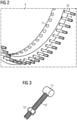
- FIGURE 2 shows a side perspective view on a part of a root portion 6 of a wind turbine blade 5 according to a first embodiment of the state of the art.
- Multiple bolted connection means 11 are arranged within the root portion 6 along the circumference of it.
- Bolts 10 are attached to the bolted connection means 11.
- the bolts 10 may be attached to a hub flange 7 or bearing 7 as shown in FIG. 1 .
- FIGURE 3 shows a side perspective view on a bolt 10 with a bolted connection means 11 and a nut 12.
- the bolted connection means 11 is a bushing in this case and has a cylindrical shape. It may be placed in corresponding cavities within the bolted connection means 11, as can be seen in FIG. 2 .
- the bolt 10 is secured by means of the bushing 11 within the root portion 6 and the hub flange 7 or bearing 7 is attached thereto, they may be secured by means of the nut 12.
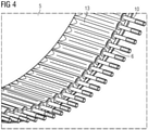
- FIGURE 4 shows a side perspective view on a part of a root portion 6 of a wind turbine blade 5 according to a second embodiment of the state of the art.
- bushings 11 instead of bushings 11 as bolted connection means, threaded inserts 13 are used for connecting the bolts 10 thereto.
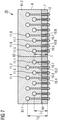
- FIGURE 5 shows a cross section of a part of a root assembly 20 according to an embodiment of the state of the art.
- Two root segments 61.1, 61.2 of the root assembly 20 are connected with each other at a root segment interface 62.
- the root segments 61.1, 61.2 may be glued or casted together, for example.
- Each of the first root segment 61.1 and the second root segment 61.2 comprise multiple staggered bolted connection means 11, such that the bolted connection means 11 are alternately located at a first distance L 1 and a second distance L 2 from a root attachment surface 64.
- the distances L 1 , L 2 are measured from the centers of the bolted connection means 11 to the root attachment face 64, in this case.
- each of the bolts 10.1...10.16 is staggered, such that the bolts 10.1...10.16 alternately have a first length L 1 and a second length L 2 .
- Each of the bolts 10.1...10.16 is secured within one of the root segments 61.1, 61.2 by means of a nut 12, thereby securing the bearing 7 or hub flange 7 to the root segments 61.1, 61.2.
- the bolted connection means 11.1 of the interface pair is provided at the distance L 2 and the bolted connection means 11.9 of the interface pair is provided at the distance L 1 from the root attachment face 64.
- the distance L 1 is less than the distance L 2 .
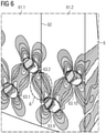
- FIGURE 6 shows a side perspective view on a shear strain contours representation of a part of the root assembly 20 of FIG. 5 .
- This representation shows the shear strain acting upon the part of the root assembly 20 when forces act on the wind turbine blade 5 during operation of the wind turbine 1.
- the bolted connection means 11 are not shown. Instead of the bolted connection means 11, the cavities 63.1, 63.2, 63.9, 63.10 for the bolted connection means 11 can be seen.
- the bolted connection means 11 are positioned within the cavities 13 and transfer the forces from the bolts 10 via the bolted connection means 11 to the root segments 61.1, 61.2. It can be seen that shear strain is applied at the root segment interface 62. This is problematic due to the root not being manufactured integral but from root segments 61.1, 61.2 joined at the root segment interface 62. Thus, the root assembly 20 is particularly susceptible to failure at the root segment interface 62.
- FIGURE 7 shows a cross section of a part of a root assembly 20 according to a first embodiment of the invention.
- the interface pair of bolted connection means 11.1, 11.5, in which the bolted connection means 11.1, 11.5 are provided within different root segments 61.1, 61.3 and arranged closest to the root segment interface 62 the two bolted connection means 11.1, 11.5 of the interface pair are provided at the same distance L from the root attachment face 64.
- the bolts 10.1, 10.5 at the root segment interface 62 are provided with equal length L.
- FIGURE 8 shows a side perspective view on a shear strain contours representation of a part of the root assembly 20 of FIG. 7 . It can be taken from FIG. 8 , that the shear strain occurring at the root segment interface 62 in the root assembly of FIG. 5 has been eliminated by means of providing the bolted connection means 11.1, 11.5 at same distance L from the root attachment face 64 within the cavities 63.1, 63.5.
- FIGURE 9 shows a cross section of a part of a root assembly 20 according to a second embodiment of the invention.
- the bolted connection means 11 of the interface pair at the root segment interface 62 are provided at same distance L 1 , L 2 from the root attachment face 64.
- the distance is measured from any point of the bolted connection means 11. As such, the distance is measured at a bottom of the bolted connection means 11.2 and at a center of the bolted connection means 11.1.
- FIGURE 10 shows a cross section of a part of a root assembly 20 according to a third embodiment of the invention.
- the at least one interface pair comprises two bolted connection means 11.1, 11.2, 11.3, 11.4 within each of the different root segments 61.1, 61.2, the two bolted connection means 11.1, 11.2, 11.3, 11.4 being arranged closest to the root segment interface 62 between the different root segments 61.1, 61.2, wherein the four bolted connection means 11.1, 11.2, 11.3, 11.4 of the at least one interface pair are provided at the same distance L from the root attachment face 64.
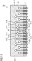
- FIGURE 11 shows a cross section of a part of a root assembly 20 according to a fourth embodiment of the invention.
- the bolted connection means 11.1, 11.2 of the interface pair at the root segment interface 62 are at a third distance L 3 from the root attachment face 64, the third distance L 3 being in between the first distance L 1 and the second distance L 2 .
- FIGURE 12 shows a cross section of a part of a root assembly 20 according to a fifth embodiment of the invention.
- both bolts 10.1, 10.2 at the root segment interface 62 have extenders 14.1, 14.2.
- the bolts 10 having the larger length of the two lengths of bolts 10 may be used at the root segment interface 62.
- FIGURE 13 shows a cross section of a part of a root assembly 20 according to a fifth embodiment of the invention.
- the bolted connection means 11.1, 11.2 of the interface pair are provided at the first distance L 1 from the root attachment face 64 and at a second root segment interface 62.2, the bolted connection means 11.3, 11.4 of the interface pair are provided at the second distance L 2 from the root attachment face 64.
- the bolted connection means 11 of every interface pair at the same distance L from the root attachment face 64.
Description
- The invention relates to a root assembly of a wind turbine blade for a wind turbine, a wind turbine blade and a wind turbine.
- Root assemblies comprise a root portion of a wind turbine blade connected to a bearing or a hub flange of the wind turbine. Generally, the bearing or hub flange is connected to the root portion by means of multiple bolts secured within bushings (see
FIG. 2 ) or threaded inserts (seeFIG. 4 ) fixedly arranged in the root portion. Here, the bushings or threaded inserts are arranged along a common circumference. - However, in particular in large wind turbines, the root assemblies must be able to resist very high loads. For this purpose, a large number of bolts and bushings or threaded inserts needs to be provided in the root assembly but the space for the bushings or threaded inserts on a common circumference of the root portion is limited. Therefore, it is known to provide the root assembly with a staggered configuration of the multiple bolts (see
FIG. 5 ). - However, by means of shear strain analysis, the inventors have found, that the root portions with a staggered configuration of the bolts are susceptible to failure at a root segment interface between root segments of the root portion (see
FIG. 6 ). This is because the root portion is not one monobloc portion but consists of different root segments connected together so as to form the root portion. For example, in a butterfly design of a wind turbine blade, the root portion typically consists of two root segments. In an integral design of a wind turbine blade, the root portion typically consists of multiple root segments joined together. - The configuration of such root assembly and the problem as well as the above reference figures and the further figures will later be explained with reference to the respective figures.
- A root assembly according to the preamble of claim 1 and being susceptible to the above described failure is known from
DK178388 B1 US2007231146 A1 . It is an object of the invention to provide an improved root assembly, wind turbine blade and wind turbine not having the previously described disadvantage, in particular having a long service life. - This object is solved by the subject-matter of the claims. In particular, the object is solved by a root assembly of a wind turbine blade of a wind turbine according to claim 1, a wind turbine blade according to claim 14 and a wind turbine according to claim 15. Further details of the invention unfold from the other claims as well as the description and the drawings. Thereby, the features and details described in connection with the root assembly of the invention apply in connection with the wind turbine blade of the invention and with the wind turbine of the invention, so that regarding the disclosure of the individual aspects of the invention it is or can be referred to one another.
- According to a first aspect of the invention, the object is solved by a root assembly of a wind turbine blade for a wind turbine, whereby (a) a root portion of the root assembly comprises at least two root segments being joined together at root segment interfaces formed between the at least two root segments, (b) a root attachment face of the root portion is attached to a bearing or a hub flange of the root assembly by means of multiple bolts, (c) each of the multiple bolts is connected to one of a multiple of bolted connection means fixedly arranged within the root segments such that the multiple bolts are arranged adjacent to each other along a circumference of the root portion and the bolted connection means are arranged adjacent to each other along the circumference of the root portion, and (d) adjacent bolted connection means are offset from one another in a way such that they are provided at different distances from the root attachment face, whereby in at least one of an interface pair of bolted connection means, wherein the bolted connection means of the at least one interface pair are provided within different root segments of the at least two root segments and are arranged closest to the root segment interface between the different root segments, the two bolted connection means of the at least one interface pair are provided at the same distance from the root attachment face.
- Thereby, the shear strain at the root segment interface between the bolted connection means of the interface pair is removed or at least reduced and thus an improved root assembly having a long service life and in particular not having the previously described disadvantages is obtained.
- In particular, the bolts may have threads on an outer circumference thereof. By means of these outer threads, they may be interlocked with inner threads of the bolted attachment means. In particular, the multiple bolts may be arranged in parallel to each other.
- The root segments may in particular have a round shape, i.e. be rounded and moreover in particular have a partially circular or elliptical shape. In other words, the root segments may form an arc or have an arc shape. The root segments may have equal or different arc lengths among them. Thereby, a cylindrically shaped root portion of the wind turbine blade may be provided. The cross section of the root portion may have a circular or an elliptical shape.
- The root segments may be reinforcement blocks (such as precured laminate blocks) that are placed on or within a shell laminate of the wind turbine blade during manufacture of the shell, or they may simply be reinforced areas of the shell constructed by additional layers placed and cured together with the rest of the shell.
- The root segments may be manufactured from a fiber composite material, in particular a fiber composite lay-up. The fiber composite material may have glass fibers and/or carbon fibers, for example.
- That the two bolted connection means of the at least one interface pair are provided at the same distance from the root attachment face means that a line parallel to the root attachment face may be drawn from one of the bolted connection means of the interface pair to the other one of the bolted connection means of the interface pair. This means, that the most distant point of one of the bolted connection means of the interface pair from the root attachment face may be connected by that parallel line to a least distant point of the other bolted connection means of the interface pair from the root attachment face. Thereby, as long as the parallel line connects the two bolted connection means, the bolted connection means are at the same distance from the root attachment face according to the invention.
- It is preferred, that the bolted connection means are bushings and/or threaded inserts. The bolts may be driven into the bushings and/or threaded inserts and thereby particularly easy connected with these.
- It is further preferred, that the multiple bolts are secured against the bearing or the hub flange by means of nuts. This is a particularly simple and easy way of securing the bearing or hub flange to the root portion.
- Moreover, it is preferred, that centers of the bolted connection means of the at least one interface pair are provided at the same distance from the root attachment face. Thereby, it can be very effectively prevented that the shear strains occur at the root segment interface.
- It is further preferred, that a distance, in particular a shortest distance, between the bolts connected to the bolted connection means of the interface pair is greater than a distance, in particular a shortest distance, between adjacent bolts connected to bolted connection means within the at least two root segments. This avoids excessive concentration of longitudinal strains between the bolted connection means at same distance from the root attachment face, and provides additional space for placement of the root segment interface and associated manufacture tolerances.
- Alternatively, or additionally it is preferred, that a circumferential distance, in particular a shortest circumferential distance, between the bolted connection means of the interface pair is greater than a circumferential distance, in particular a shortest circumferential distance, between bolted connection means within the at least two root segments. The circumferential distance is measured along the circumference of the root portion instead of measuring the direct distance between the bolted connection means. Thereby, the circumferential distance between the bolted connection means is independent from their distance from the root attachment face. That is, to measure the circumferential distance between two bolted connection means, imaginary lines are drawn from each of the two bolted connection to the root attachment face such that they are parallel to each other. The circumferential distance is measured along the circumference of the root portion and between the two imaginary lines being parallel to each other.
- Also, it is preferred, that the at least one interface pair comprises two bolted connection means within each of the different root segments, the two bolted connection means being arranged closest to the root segment interface between the different root segments, wherein the four bolted connection means of the at least one interface pair are provided at the same distance from the root attachment face. Thereby, it can be very effectively prevented that the shear strains occur at the root segment interface.
- It is also preferred, that adjacent bolts are offset from one another within the respective root segments in that they are provided with different lengths within the root segments, whereby in at least one of an interface pair of bolts, wherein the bolts of the at least one interface pair are provided within different root segments of the at least two root segments and are arranged closest to the root segment interface between the different root segments, the two bolts of the at last one interface pair are provided with the same length.
- It is further preferred, that the multiple bolts have a first length or a second length, wherein the second length is greater than the first length, and wherein the bolts of the multiple bolts having the first length and the bolts of the multiple bolts having second length are alternately connected to the adjacent offset bolted connection means. By providing the multiple bolts in two lengths, the assembly of the root assembly is simplified and provided at little cost.
- Moreover, it is preferred, that the bolted connection means of the at least one interface pair are connected either with the bolts having the first length or with the bolts having the second length.
- Further, it is preferred, that the bolted connection means of the at least one interface pair are connected with bolts having a third length, wherein the third length is different from the first length and the second length. Thereby, the assembly of the root assembly is further simplified, because the bolts to be used at the root segment interfaces can be easily distinguished by means of their length from the other bolts.
- Moreover, it is preferred, that the third length is in between the first length and the second length. Thereby, the shear strain distribution in the root portion may be further improved.
- Further, at least one of the bolts may be provided with an extender. The extender is arranged on the bolt between the nut and the bearing or the hub flange. Thereby, the nut is secured against the extender instead of directly to the bearing or hub flange. Depending on the length of the extender used, the length of the bolt within the root segment may be adjusted. Thereby, all the multiple bolts may be provided having the same length to provide particularly cost-effective parts and still may be arranged in the staggered manner, for example.
- According to a second aspect of the invention, the object is solved by a wind turbine blade comprising the root assembly according to the first aspect of the invention.
- According to a third aspect of the invention, the object is solved by a wind turbine comprising at least one wind turbine blade according to the second aspect of the invention.
- The wind turbine may be a direct drive wind turbine or a geared wind turbine, for example. Further, the at least one wind turbine blade may be mounted on an outer ring of a pitch bearing of the wind turbine or on an inner ring of the pitch bearing.
- Further advantages, features and details of the invention unfold from the following description, in which by reference to drawings
FIG. 1 to 13 embodiments of the present invention are described in detail. In the drawings, there is schematically shown: - FIG. 1
- a side perspective view on a wind turbine,
- FIG. 2
- a side perspective view on a part of a root portion of a wind turbine blade according to a first embodiment of the state of the art,
- FIG. 3
- a side perspective view on a bolt with a bolted connection means and a nut,
- FIG. 4
- a side perspective view on a part of a root portion of a wind turbine blade according to a second embodiment of the state of the art,
- FIG. 5
- a cross section of a part of a root assembly according to an embodiment of the state of the art,
- FIG. 6
- a side perspective view on a shear strain contours representation of a part of the root assembly of
FIG. 5 , - FIG. 7
- a cross section of a part of a root assembly according to a first embodiment of the invention,
- FIG. 8
- a side perspective view on a shear strain contours representation of a part of the root assembly of
FIG. 7 , - FIG. 9
- a cross section of a part of a root assembly according to a second embodiment of the invention,
- FIG. 10
- a cross section of a part of a root assembly according to a third embodiment of the invention,
- FIG. 11
- a cross section of a part of a root assembly according to a fourth embodiment of the invention,
- FIG. 12
- a cross section of a part of a root assembly according to a fifth embodiment of the invention, and
- FIG. 13
- a cross section of a part of a root assembly according to a sixth embodiment of the invention.
- Same objects in
FIGS. 1 to 13 are denominated with the same reference number. If there is more than one object of the same kind in one of the figures, the objects are numbered in ascending order with the ascending number of the object being separated from its reference number by a dot. The specific dimensions of features and parts in the figures are exemplary and may be enlarged for ease of reference only. -
FIGURE 1 shows a wind turbine 1 according to an embodiment of the invention. The wind turbine 1 comprises arotor 2 having three wind turbine blades 5.1, 5.2, 5.3 connected to ahub 3. However, the number ofwind turbine blades 10 may be at least onewind turbine blade 5, twowind turbine blades 5 or more than threewind turbine blades 5 and chosen as required for a certain setup of a wind turbine 1. - The
hub 3 is connected to a generator (not shown) arranged inside anacelle 4. During operation of the wind turbine 1, thewind turbine blades 5 are driven by wind to rotate and the wind's kinetic energy is converted into electrical energy by the generator in thenacelle 4. - The
nacelle 4 is arranged at the upper end of atower 8 of the wind turbine 1. Thetower 8 is erected on afoundation 9 such as a monopile or tripile. Thefoundation 9 is connected to and/or driven into the ground or seabed. - Each of the wind turbine blades 5.1, 5.2, 5.3 has a root portion 6.1, 6.2. These root portions 6.1, 6.2 are connected to the
hub 3 by means of bearings 7.1, 7.2 or hub flanges 7.1, 7.2. In this particular view, theroot portion 6 andbearing 7 orhub flange 7 of the wind turbine blade 5.3 is covered by thehub 3. -
FIGURE 2 shows a side perspective view on a part of aroot portion 6 of awind turbine blade 5 according to a first embodiment of the state of the art. Multiple bolted connection means 11 are arranged within theroot portion 6 along the circumference of it.Bolts 10 are attached to the bolted connection means 11. Thebolts 10 may be attached to ahub flange 7 orbearing 7 as shown inFIG. 1 . -
FIGURE 3 shows a side perspective view on abolt 10 with a bolted connection means 11 and anut 12. The bolted connection means 11 is a bushing in this case and has a cylindrical shape. It may be placed in corresponding cavities within the bolted connection means 11, as can be seen inFIG. 2 . When thebolt 10 is secured by means of thebushing 11 within theroot portion 6 and thehub flange 7 orbearing 7 is attached thereto, they may be secured by means of thenut 12. -
FIGURE 4 shows a side perspective view on a part of aroot portion 6 of awind turbine blade 5 according to a second embodiment of the state of the art. Here, instead ofbushings 11 as bolted connection means, threadedinserts 13 are used for connecting thebolts 10 thereto. -
FIGURE 5 shows a cross section of a part of aroot assembly 20 according to an embodiment of the state of the art. Two root segments 61.1, 61.2 of theroot assembly 20 are connected with each other at aroot segment interface 62. The root segments 61.1, 61.2 may be glued or casted together, for example. Each of the first root segment 61.1 and the second root segment 61.2 comprise multiple staggered bolted connection means 11, such that the bolted connection means 11 are alternately located at a first distance L1 and a second distance L2 from aroot attachment surface 64. The distances L1, L2 are measured from the centers of the bolted connection means 11 to theroot attachment face 64, in this case. Thereby, the multiple bolts 10.1...10.16 are staggered, such that the bolts 10.1...10.16 alternately have a first length L1 and a second length L2. Each of the bolts 10.1...10.16 is secured within one of the root segments 61.1, 61.2 by means of anut 12, thereby securing thebearing 7 orhub flange 7 to the root segments 61.1, 61.2. - In an interface pair of the bolted connection means 11.1, 11.9 provided within different root segments 61.1, 61.2 and arranged closest to the
root segment interface 62, the bolted connection means 11.1 of the interface pair is provided at the distance L2 and the bolted connection means 11.9 of the interface pair is provided at the distance L1 from theroot attachment face 64. The distance L1 is less than the distance L2. -
FIGURE 6 shows a side perspective view on a shear strain contours representation of a part of theroot assembly 20 ofFIG. 5 . This representation shows the shear strain acting upon the part of theroot assembly 20 when forces act on thewind turbine blade 5 during operation of the wind turbine 1. - In this view, the bolted connection means 11 are not shown. Instead of the bolted connection means 11, the cavities 63.1, 63.2, 63.9, 63.10 for the bolted connection means 11 can be seen. The bolted connection means 11 are positioned within the
cavities 13 and transfer the forces from thebolts 10 via the bolted connection means 11 to the root segments 61.1, 61.2. It can be seen that shear strain is applied at theroot segment interface 62. This is problematic due to the root not being manufactured integral but from root segments 61.1, 61.2 joined at theroot segment interface 62. Thus, theroot assembly 20 is particularly susceptible to failure at theroot segment interface 62. -
FIGURE 7 shows a cross section of a part of aroot assembly 20 according to a first embodiment of the invention. Contrary to theroot assembly 20 according to the embodiment of the state of the art as depicted inFIGS. 5 and6 , the interface pair of bolted connection means 11.1, 11.5, in which the bolted connection means 11.1, 11.5 are provided within different root segments 61.1, 61.3 and arranged closest to theroot segment interface 62, the two bolted connection means 11.1, 11.5 of the interface pair are provided at the same distance L from theroot attachment face 64. Further, the bolts 10.1, 10.5 at theroot segment interface 62 are provided with equal length L. -
FIGURE 8 shows a side perspective view on a shear strain contours representation of a part of theroot assembly 20 ofFIG. 7 . It can be taken fromFIG. 8 , that the shear strain occurring at theroot segment interface 62 in the root assembly ofFIG. 5 has been eliminated by means of providing the bolted connection means 11.1, 11.5 at same distance L from theroot attachment face 64 within the cavities 63.1, 63.5. -
FIGURE 9 shows a cross section of a part of aroot assembly 20 according to a second embodiment of the invention. In this second embodiment, the bolted connection means 11 of the interface pair at theroot segment interface 62 are provided at same distance L1, L2 from theroot attachment face 64. However, the distance is measured from any point of the bolted connection means 11. As such, the distance is measured at a bottom of the bolted connection means 11.2 and at a center of the bolted connection means 11.1. -
FIGURE 10 shows a cross section of a part of aroot assembly 20 according to a third embodiment of the invention. According to the third embodiment, the at least one interface pair comprises two bolted connection means 11.1, 11.2, 11.3, 11.4 within each of the different root segments 61.1, 61.2, the two bolted connection means 11.1, 11.2, 11.3, 11.4 being arranged closest to theroot segment interface 62 between the different root segments 61.1, 61.2, wherein the four bolted connection means 11.1, 11.2, 11.3, 11.4 of the at least one interface pair are provided at the same distance L from theroot attachment face 64. -
FIGURE 11 shows a cross section of a part of aroot assembly 20 according to a fourth embodiment of the invention. According to this fourth embodiment, the bolted connection means 11.1, 11.2 of the interface pair at theroot segment interface 62 are at a third distance L3 from theroot attachment face 64, the third distance L3 being in between the first distance L1 and the second distance L2. -
FIGURE 12 shows a cross section of a part of aroot assembly 20 according to a fifth embodiment of the invention. According to this fifth embodiment, both bolts 10.1, 10.2 at theroot segment interface 62 have extenders 14.1, 14.2. Thereby, thebolts 10 having the larger length of the two lengths ofbolts 10 may be used at theroot segment interface 62. -
FIGURE 13 shows a cross section of a part of aroot assembly 20 according to a fifth embodiment of the invention. At a first root segment interface 62.1, the bolted connection means 11.1, 11.2 of the interface pair are provided at the first distance L1 from theroot attachment face 64 and at a second root segment interface 62.2, the bolted connection means 11.3, 11.4 of the interface pair are provided at the second distance L2 from theroot attachment face 64. Thus, it is not necessary to provide the bolted connection means 11 of every interface pair at the same distance L from theroot attachment face 64. Further, it is not necessary to provide all thebolts 10 at the root segment interfaces 62 with the same length L but merely that the pairs ofbolts 10 at the root segment interfaces 62 are of equal length.
Claims (15)
- Root assembly (20) of a wind turbine blade (5) for a wind turbine (1), whereby(a) a root portion (6) of the root assembly (20) comprises at least two root segments (61) being joined together at root segment interfaces (62) formed between the at least two root segments (61),(b) a root attachment face (64) of the root portion (6) is attached to a bearing (7) or a hub flange (7) of the root assembly (20) by means of multiple bolts (10),(c) each of the multiple bolts (10) is connected to one of a multiple of bolted connection means (11, 13) fixedly arranged within the root segments (61) such that the multiple bolts (10) are arranged adjacent to each other along a circumference of the root portion (6) and the bolted connection means (11, 13) are arranged adjacent to each other along the circumference of the root portion (6), and(d) adjacent bolted connection means (11, 13) are offset from one another in a way such that they are provided at different distances (L) from the root attachment face (64),characterized in that,
in at least one of an interface pair of bolted connection means (11, 13), wherein the bolted connection means (11, 13) of the at least one interface pair are provided within different root segments (61) of the at least two root segments (61) and are arranged closest to the root segment interface (62) between the different root segments (61), the two bolted connection means (11, 13) of the at least one interface pair are provided at the same distance (L) from the root attachment face (64). - Root assembly according to claim 1,
characterized in that,
the bolted connection means (11, 13) are bushings (11) and/or threaded inserts (13). - Root assembly according to claim 1 or 2,
characterized in that,
the multiple bolts (10) are secured against the bearing (7) or the hub flange (7) by means of nuts (12). - Root assembly according to any of the previous claims,
characterized in that,
centers of the bolted connection means (11, 13) of the at least one interface pair are provided at the same distance (L) from the root attachment face (64). - Root assembly according to any of the previous claims,
characterized in that,
a distance between the bolts (10) connected to the bolted connection means (11, 13) of the interface pair is greater than a distance between adjacent bolts (10) connected to bolted connection means (11, 13) within the at least two root segments (61). - Root assembly according to any of the previous claims,
characterized in that,
a circumferential distance between the bolted connection means (11, 13) of the interface pair is greater than a circumferential distance between bolted connection means (11, 13) within the at least two root segments (61). - Root assembly according to any of the previous claims,
characterized in that,
the at least one interface pair comprises two bolted connection means (11, 13) within each of the different root segments (61), the two bolted connection means (11, 13) being arranged closest to the root segment interface (62) between the different root segments (61), wherein the four bolted connection means (11, 13) of the at least one interface pair are provided at the same distance (L) from the root attachment face (64). - Root assembly according to any of the previous claims,
characterized in that,
adjacent bolts (10) are offset from one another within the respective root segments (61) in that they are provided with different lengths (L) within the root segments (61), whereby in at least one of an interface pair of bolts (10), wherein the bolts (10) of the at least one interface pair are provided within different root segments (61) of the at least two root segments (61) and are arranged closest to the root segment interface (62) between the different root segments (61), the two bolts (10) of the at last one interface pair are provided with the same length (L). - Root assembly according to any of the previous claims,
characterized in that,
the multiple bolts (10) have a first length or a second length, wherein the second length is greater than the first length, and wherein the bolts (10) of the multiple bolts (10) having the first length and the bolts (10) of the multiple bolts (10) having the second length are alternately connected to the adjacent offset bolted connection means (11, 13). - Root assembly according to claim 9,
characterized in that,
the bolted connection means (11, 13) of the at least one interface pair are connected either with the bolts (10) having the first length or with the bolts (10) having the second length. - Root assembly according to claim 9,
characterized in that,
the bolted connection means (11, 13) of the at least one interface pair are connected with bolts (10) having a third length, wherein the third length is different from the first length and the second length. - Root assembly according to claim 11,
characterized in that,
the third length is in between the first length and the second length. - Root assembly according to any of the previous claims,
characterized in that,
at least one of the bolts (10) is provided with an extender (14) . - Wind turbine blade (5) comprising the root assembly (20) according to any of the previous claims.
- Wind turbine (1) comprising at least one wind turbine blade (5) according to claim 14.
Priority Applications (9)
| Application Number | Priority Date | Filing Date | Title |
|---|---|---|---|
| DK19216698.1T DK3839246T3 (en) | 2019-12-16 | 2019-12-16 | Root joint of a wind turbine blade for a wind turbine, wind turbine blade and wind turbine |
| PT192166981T PT3839246T (en) | 2019-12-16 | 2019-12-16 | Root assembly of a wind turbine blade for a wind turbine, wind turbine blade and wind turbine |
| ES19216698T ES2910047T3 (en) | 2019-12-16 | 2019-12-16 | Base mounting of a wind turbine blade for a wind turbine, wind turbine blade and wind turbine |
| EP19216698.1A EP3839246B1 (en) | 2019-12-16 | 2019-12-16 | Root assembly of a wind turbine blade for a wind turbine, wind turbine blade and wind turbine |
| US17/784,214 US11761419B2 (en) | 2019-12-16 | 2020-12-10 | Root assembly of a wind turbine blade for a wind turbine, wind turbine blade and wind turbine |
| CN202080087364.1A CN114787499A (en) | 2019-12-16 | 2020-12-10 | Root assembly for a wind turbine blade of a wind turbine, wind turbine blade and wind turbine |
| BR112022010296A BR112022010296A2 (en) | 2019-12-16 | 2020-12-10 | ROOT ASSEMBLY OF A WIND TURBINE BLADE FOR A WIND TURBINE, WIND TURBINE BLADE AND WIND TURBINE |
| PCT/EP2020/085454 WO2021122275A1 (en) | 2019-12-16 | 2020-12-10 | Root assembly of a wind turbine blade for a wind turbine, wind turbine blade and wind turbine |
| TW109144230A TWI756985B (en) | 2019-12-16 | 2020-12-15 | Root assembly of a wind turbine blade for a wind turbine, wind turbine blade and wind turbine |
Applications Claiming Priority (1)
| Application Number | Priority Date | Filing Date | Title |
|---|---|---|---|
| EP19216698.1A EP3839246B1 (en) | 2019-12-16 | 2019-12-16 | Root assembly of a wind turbine blade for a wind turbine, wind turbine blade and wind turbine |
Publications (2)
| Publication Number | Publication Date |
|---|---|
| EP3839246A1 EP3839246A1 (en) | 2021-06-23 |
| EP3839246B1 true EP3839246B1 (en) | 2022-01-19 |
Family
ID=68917709
Family Applications (1)
| Application Number | Title | Priority Date | Filing Date |
|---|---|---|---|
| EP19216698.1A Active EP3839246B1 (en) | 2019-12-16 | 2019-12-16 | Root assembly of a wind turbine blade for a wind turbine, wind turbine blade and wind turbine |
Country Status (9)
| Country | Link |
|---|---|
| US (1) | US11761419B2 (en) |
| EP (1) | EP3839246B1 (en) |
| CN (1) | CN114787499A (en) |
| BR (1) | BR112022010296A2 (en) |
| DK (1) | DK3839246T3 (en) |
| ES (1) | ES2910047T3 (en) |
| PT (1) | PT3839246T (en) |
| TW (1) | TWI756985B (en) |
| WO (1) | WO2021122275A1 (en) |
Families Citing this family (2)
| Publication number | Priority date | Publication date | Assignee | Title |
|---|---|---|---|---|
| ES2940570T3 (en) * | 2020-01-15 | 2023-05-09 | Siemens Gamesa Renewable Energy As | Root portion of a wind turbine blade, wind turbine blade, root and wind turbine assembly |
| EP4116574A1 (en) * | 2021-07-05 | 2023-01-11 | Siemens Gamesa Renewable Energy A/S | Root assembly of a wind turbine blade for a wind turbine, wind turbine blade and wind turbine |
Family Cites Families (8)
| Publication number | Priority date | Publication date | Assignee | Title |
|---|---|---|---|---|
| FR2821129B1 (en) * | 2001-02-22 | 2003-05-16 | Eads Airbus Sa | DEVICE FOR ASSEMBLING A PANEL AND A STRUCTURE, CAPABLE OF TRANSMITTING IMPORTANT EFFORTS |
| DE102006014742B4 (en) * | 2006-03-30 | 2008-01-24 | Nordex Energy Gmbh | Rotor blade for wind turbines |
| US7517194B2 (en) | 2006-04-30 | 2009-04-14 | General Electric Company | Rotor blade for a wind turbine |
| DE102011088025A1 (en) * | 2011-12-08 | 2013-06-13 | Wobben Properties Gmbh | Rotor blade for horizontal axle wind turbine, has anchoring element anchored in blade outer part, counter element anchored in blade inner part, and connecting bolts reaching through counter element and fastened in anchoring element |
| US9777704B2 (en) * | 2014-11-03 | 2017-10-03 | General Electric Company | Rotor blade assembly for a wind turbine having variable-length blade bolts |
| CN209704748U (en) | 2018-12-24 | 2019-11-29 | 天津松英科技发展有限公司 | Punching type bolt connecting device after a kind of large scale wind power machine blade |
| CN209671147U (en) | 2018-12-29 | 2019-11-22 | 中材科技(酒泉)风电叶片有限公司 | A kind of wind electricity blade blade root precuring heating device |
| TWM584371U (en) | 2019-06-28 | 2019-10-01 | 天力離岸風電科技股份有限公司 | Blade root of wind drive generator blade |
-
2019
- 2019-12-16 EP EP19216698.1A patent/EP3839246B1/en active Active
- 2019-12-16 DK DK19216698.1T patent/DK3839246T3/en active
- 2019-12-16 PT PT192166981T patent/PT3839246T/en unknown
- 2019-12-16 ES ES19216698T patent/ES2910047T3/en active Active
-
2020
- 2020-12-10 US US17/784,214 patent/US11761419B2/en active Active
- 2020-12-10 WO PCT/EP2020/085454 patent/WO2021122275A1/en active Application Filing
- 2020-12-10 BR BR112022010296A patent/BR112022010296A2/en unknown
- 2020-12-10 CN CN202080087364.1A patent/CN114787499A/en active Pending
- 2020-12-15 TW TW109144230A patent/TWI756985B/en active
Also Published As
| Publication number | Publication date |
|---|---|
| US11761419B2 (en) | 2023-09-19 |
| TW202132685A (en) | 2021-09-01 |
| TWI756985B (en) | 2022-03-01 |
| US20230041043A1 (en) | 2023-02-09 |
| EP3839246A1 (en) | 2021-06-23 |
| BR112022010296A2 (en) | 2022-08-09 |
| CN114787499A (en) | 2022-07-22 |
| PT3839246T (en) | 2022-01-27 |
| ES2910047T3 (en) | 2022-05-11 |
| DK3839246T3 (en) | 2022-02-07 |
| WO2021122275A1 (en) | 2021-06-24 |
Similar Documents
| Publication | Publication Date | Title |
|---|---|---|
| US7517194B2 (en) | Rotor blade for a wind turbine | |
| EP2622212B1 (en) | Vertical axis wind turbine having one or more modular blades | |
| EP2933476B1 (en) | Reinforced pitch bearing of a wind turbine | |
| US9239040B2 (en) | Root end assembly configuration for a wind turbine rotor blade and associated forming methods | |
| EP2917568B1 (en) | Wind turbine blade with fastening means | |
| US11761419B2 (en) | Root assembly of a wind turbine blade for a wind turbine, wind turbine blade and wind turbine | |
| EP1956235A1 (en) | Blade for a wind turbine | |
| JP5597697B2 (en) | Windmill | |
| EP2697047B1 (en) | Wind turbine blade comprising cylindrical metal inserts in a root region thereof | |
| US11639709B2 (en) | Wind turbine rotor blade and method for assembling a wind turbine rotor blade | |
| EP4116574A1 (en) | Root assembly of a wind turbine blade for a wind turbine, wind turbine blade and wind turbine | |
| EP4116573A1 (en) | Root assembly of a wind turbine blade for a wind turbine, wind turbine blade and wind turbine | |
| EP3168457B1 (en) | Wind turbine with blades with a coning angle | |
| EP3851666B1 (en) | Root portion of a wind turbine blade, wind turbine blade, root assembly and wind turbine | |
| CN219139256U (en) | Blade root connection structure and wind generating set | |
| CN117685170A (en) | Steel-UHPC combined wind power tower barrel and construction method thereof | |
| EP3845760A1 (en) | Pitch bearing of a wind turbine, wind turbine and method of limiting the stresses in the reinforcement plates of a pitch bearing | |
| EP2532882A1 (en) | System and methods for assembling a wind turbine with a pitch assembly |
Legal Events
| Date | Code | Title | Description |
|---|---|---|---|
| PUAI | Public reference made under article 153(3) epc to a published international application that has entered the european phase |
Free format text: ORIGINAL CODE: 0009012 |
|
| STAA | Information on the status of an ep patent application or granted ep patent |
Free format text: STATUS: REQUEST FOR EXAMINATION WAS MADE |
|
| 17P | Request for examination filed |
Effective date: 20200720 |
|
| AK | Designated contracting states |
Kind code of ref document: A1 Designated state(s): AL AT BE BG CH CY CZ DE DK EE ES FI FR GB GR HR HU IE IS IT LI LT LU LV MC MK MT NL NO PL PT RO RS SE SI SK SM TR |
|
| GRAP | Despatch of communication of intention to grant a patent |
Free format text: ORIGINAL CODE: EPIDOSNIGR1 |
|
| STAA | Information on the status of an ep patent application or granted ep patent |
Free format text: STATUS: GRANT OF PATENT IS INTENDED |
|
| INTG | Intention to grant announced |
Effective date: 20210824 |
|
| GRAS | Grant fee paid |
Free format text: ORIGINAL CODE: EPIDOSNIGR3 |
|
| GRAA | (expected) grant |
Free format text: ORIGINAL CODE: 0009210 |
|
| STAA | Information on the status of an ep patent application or granted ep patent |
Free format text: STATUS: THE PATENT HAS BEEN GRANTED |
|
| AK | Designated contracting states |
Kind code of ref document: B1 Designated state(s): AL AT BE BG CH CY CZ DE DK EE ES FI FR GB GR HR HU IE IS IT LI LT LU LV MC MK MT NL NO PL PT RO RS SE SI SK SM TR |
|
| REG | Reference to a national code |
Ref country code: GB Ref legal event code: FG4D |
|
| REG | Reference to a national code |
Ref country code: PT Ref legal event code: SC4A Ref document number: 3839246 Country of ref document: PT Date of ref document: 20220127 Kind code of ref document: T Free format text: AVAILABILITY OF NATIONAL TRANSLATION Effective date: 20220120 |
|
| REG | Reference to a national code |
Ref country code: CH Ref legal event code: EP |
|
| REG | Reference to a national code |
Ref country code: DK Ref legal event code: T3 Effective date: 20220131 |
|
| REG | Reference to a national code |
Ref country code: DE Ref legal event code: R096 Ref document number: 602019011029 Country of ref document: DE |
|
| REG | Reference to a national code |
Ref country code: AT Ref legal event code: REF Ref document number: 1463927 Country of ref document: AT Kind code of ref document: T Effective date: 20220215 |
|
| REG | Reference to a national code |
Ref country code: IE Ref legal event code: FG4D |
|
| REG | Reference to a national code |
Ref country code: NL Ref legal event code: FP |
|
| REG | Reference to a national code |
Ref country code: LT Ref legal event code: MG9D |
|
| REG | Reference to a national code |
Ref country code: ES Ref legal event code: FG2A Ref document number: 2910047 Country of ref document: ES Kind code of ref document: T3 Effective date: 20220511 |
|
| REG | Reference to a national code |
Ref country code: AT Ref legal event code: MK05 Ref document number: 1463927 Country of ref document: AT Kind code of ref document: T Effective date: 20220119 |
|
| PG25 | Lapsed in a contracting state [announced via postgrant information from national office to epo] |
Ref country code: SE Free format text: LAPSE BECAUSE OF FAILURE TO SUBMIT A TRANSLATION OF THE DESCRIPTION OR TO PAY THE FEE WITHIN THE PRESCRIBED TIME-LIMIT Effective date: 20220119 Ref country code: RS Free format text: LAPSE BECAUSE OF FAILURE TO SUBMIT A TRANSLATION OF THE DESCRIPTION OR TO PAY THE FEE WITHIN THE PRESCRIBED TIME-LIMIT Effective date: 20220119 Ref country code: NO Free format text: LAPSE BECAUSE OF FAILURE TO SUBMIT A TRANSLATION OF THE DESCRIPTION OR TO PAY THE FEE WITHIN THE PRESCRIBED TIME-LIMIT Effective date: 20220419 Ref country code: LT Free format text: LAPSE BECAUSE OF FAILURE TO SUBMIT A TRANSLATION OF THE DESCRIPTION OR TO PAY THE FEE WITHIN THE PRESCRIBED TIME-LIMIT Effective date: 20220119 Ref country code: HR Free format text: LAPSE BECAUSE OF FAILURE TO SUBMIT A TRANSLATION OF THE DESCRIPTION OR TO PAY THE FEE WITHIN THE PRESCRIBED TIME-LIMIT Effective date: 20220119 Ref country code: BG Free format text: LAPSE BECAUSE OF FAILURE TO SUBMIT A TRANSLATION OF THE DESCRIPTION OR TO PAY THE FEE WITHIN THE PRESCRIBED TIME-LIMIT Effective date: 20220419 |
|
| REG | Reference to a national code |
Ref country code: DE Ref legal event code: R082 Ref document number: 602019011029 Country of ref document: DE Representative=s name: SAUTHOFF, KARSTEN, DIPL.-ING. UNIV., DE |
|
| PG25 | Lapsed in a contracting state [announced via postgrant information from national office to epo] |
Ref country code: PL Free format text: LAPSE BECAUSE OF FAILURE TO SUBMIT A TRANSLATION OF THE DESCRIPTION OR TO PAY THE FEE WITHIN THE PRESCRIBED TIME-LIMIT Effective date: 20220119 Ref country code: LV Free format text: LAPSE BECAUSE OF FAILURE TO SUBMIT A TRANSLATION OF THE DESCRIPTION OR TO PAY THE FEE WITHIN THE PRESCRIBED TIME-LIMIT Effective date: 20220119 Ref country code: GR Free format text: LAPSE BECAUSE OF FAILURE TO SUBMIT A TRANSLATION OF THE DESCRIPTION OR TO PAY THE FEE WITHIN THE PRESCRIBED TIME-LIMIT Effective date: 20220420 Ref country code: FI Free format text: LAPSE BECAUSE OF FAILURE TO SUBMIT A TRANSLATION OF THE DESCRIPTION OR TO PAY THE FEE WITHIN THE PRESCRIBED TIME-LIMIT Effective date: 20220119 Ref country code: AT Free format text: LAPSE BECAUSE OF FAILURE TO SUBMIT A TRANSLATION OF THE DESCRIPTION OR TO PAY THE FEE WITHIN THE PRESCRIBED TIME-LIMIT Effective date: 20220119 |
|
| PG25 | Lapsed in a contracting state [announced via postgrant information from national office to epo] |
Ref country code: IS Free format text: LAPSE BECAUSE OF FAILURE TO SUBMIT A TRANSLATION OF THE DESCRIPTION OR TO PAY THE FEE WITHIN THE PRESCRIBED TIME-LIMIT Effective date: 20220519 |
|
| REG | Reference to a national code |
Ref country code: DE Ref legal event code: R097 Ref document number: 602019011029 Country of ref document: DE |
|
| PG25 | Lapsed in a contracting state [announced via postgrant information from national office to epo] |
Ref country code: SM Free format text: LAPSE BECAUSE OF FAILURE TO SUBMIT A TRANSLATION OF THE DESCRIPTION OR TO PAY THE FEE WITHIN THE PRESCRIBED TIME-LIMIT Effective date: 20220119 Ref country code: SK Free format text: LAPSE BECAUSE OF FAILURE TO SUBMIT A TRANSLATION OF THE DESCRIPTION OR TO PAY THE FEE WITHIN THE PRESCRIBED TIME-LIMIT Effective date: 20220119 Ref country code: RO Free format text: LAPSE BECAUSE OF FAILURE TO SUBMIT A TRANSLATION OF THE DESCRIPTION OR TO PAY THE FEE WITHIN THE PRESCRIBED TIME-LIMIT Effective date: 20220119 Ref country code: EE Free format text: LAPSE BECAUSE OF FAILURE TO SUBMIT A TRANSLATION OF THE DESCRIPTION OR TO PAY THE FEE WITHIN THE PRESCRIBED TIME-LIMIT Effective date: 20220119 Ref country code: CZ Free format text: LAPSE BECAUSE OF FAILURE TO SUBMIT A TRANSLATION OF THE DESCRIPTION OR TO PAY THE FEE WITHIN THE PRESCRIBED TIME-LIMIT Effective date: 20220119 |
|
| PLBE | No opposition filed within time limit |
Free format text: ORIGINAL CODE: 0009261 |
|
| STAA | Information on the status of an ep patent application or granted ep patent |
Free format text: STATUS: NO OPPOSITION FILED WITHIN TIME LIMIT |
|
| PG25 | Lapsed in a contracting state [announced via postgrant information from national office to epo] |
Ref country code: AL Free format text: LAPSE BECAUSE OF FAILURE TO SUBMIT A TRANSLATION OF THE DESCRIPTION OR TO PAY THE FEE WITHIN THE PRESCRIBED TIME-LIMIT Effective date: 20220119 |
|
| 26N | No opposition filed |
Effective date: 20221020 |
|
| PGFP | Annual fee paid to national office [announced via postgrant information from national office to epo] |
Ref country code: ES Payment date: 20230119 Year of fee payment: 4 |
|
| PG25 | Lapsed in a contracting state [announced via postgrant information from national office to epo] |
Ref country code: IT Free format text: LAPSE BECAUSE OF FAILURE TO SUBMIT A TRANSLATION OF THE DESCRIPTION OR TO PAY THE FEE WITHIN THE PRESCRIBED TIME-LIMIT Effective date: 20220119 |
|
| REG | Reference to a national code |
Ref country code: CH Ref legal event code: PL |
|
| REG | Reference to a national code |
Ref country code: BE Ref legal event code: MM Effective date: 20221231 |
|
| PG25 | Lapsed in a contracting state [announced via postgrant information from national office to epo] |
Ref country code: LU Free format text: LAPSE BECAUSE OF NON-PAYMENT OF DUE FEES Effective date: 20221216 |
|
| PG25 | Lapsed in a contracting state [announced via postgrant information from national office to epo] |
Ref country code: LI Free format text: LAPSE BECAUSE OF NON-PAYMENT OF DUE FEES Effective date: 20221231 Ref country code: IE Free format text: LAPSE BECAUSE OF NON-PAYMENT OF DUE FEES Effective date: 20221216 Ref country code: CH Free format text: LAPSE BECAUSE OF NON-PAYMENT OF DUE FEES Effective date: 20221231 |
|
| PG25 | Lapsed in a contracting state [announced via postgrant information from national office to epo] |
Ref country code: BE Free format text: LAPSE BECAUSE OF NON-PAYMENT OF DUE FEES Effective date: 20221231 |
|
| PGFP | Annual fee paid to national office [announced via postgrant information from national office to epo] |
Ref country code: GB Payment date: 20231220 Year of fee payment: 5 |
|
| PGFP | Annual fee paid to national office [announced via postgrant information from national office to epo] |
Ref country code: PT Payment date: 20231213 Year of fee payment: 5 Ref country code: NL Payment date: 20231219 Year of fee payment: 5 Ref country code: FR Payment date: 20231219 Year of fee payment: 5 Ref country code: DK Payment date: 20231219 Year of fee payment: 5 Ref country code: DE Payment date: 20231214 Year of fee payment: 5 |
|
| PGFP | Annual fee paid to national office [announced via postgrant information from national office to epo] |
Ref country code: ES Payment date: 20240118 Year of fee payment: 5 |