EP3839210B1 - Rotor assembly and rotating machine - Google Patents
Rotor assembly and rotating machine Download PDFInfo
- Publication number
- EP3839210B1 EP3839210B1 EP19864552.5A EP19864552A EP3839210B1 EP 3839210 B1 EP3839210 B1 EP 3839210B1 EP 19864552 A EP19864552 A EP 19864552A EP 3839210 B1 EP3839210 B1 EP 3839210B1
- Authority
- EP
- European Patent Office
- Prior art keywords
- rotor
- rolling element
- curved surface
- rotor assembly
- shaped plate
- Prior art date
- Legal status (The legal status is an assumption and is not a legal conclusion. Google has not performed a legal analysis and makes no representation as to the accuracy of the status listed.)
- Active
Links
Images




Classifications
-
- F—MECHANICAL ENGINEERING; LIGHTING; HEATING; WEAPONS; BLASTING
- F01—MACHINES OR ENGINES IN GENERAL; ENGINE PLANTS IN GENERAL; STEAM ENGINES
- F01D—NON-POSITIVE DISPLACEMENT MACHINES OR ENGINES, e.g. STEAM TURBINES
- F01D5/00—Blades; Blade-carrying members; Heating, heat-insulating, cooling or antivibration means on the blades or the members
- F01D5/02—Blade-carrying members, e.g. rotors
- F01D5/021—Blade-carrying members, e.g. rotors for flow machines or engines with only one axial stage
-
- F—MECHANICAL ENGINEERING; LIGHTING; HEATING; WEAPONS; BLASTING
- F04—POSITIVE - DISPLACEMENT MACHINES FOR LIQUIDS; PUMPS FOR LIQUIDS OR ELASTIC FLUIDS
- F04D—NON-POSITIVE-DISPLACEMENT PUMPS
- F04D29/00—Details, component parts, or accessories
- F04D29/26—Rotors specially for elastic fluids
- F04D29/32—Rotors specially for elastic fluids for axial flow pumps
- F04D29/321—Rotors specially for elastic fluids for axial flow pumps for axial flow compressors
- F04D29/324—Blades
-
- F—MECHANICAL ENGINEERING; LIGHTING; HEATING; WEAPONS; BLASTING
- F01—MACHINES OR ENGINES IN GENERAL; ENGINE PLANTS IN GENERAL; STEAM ENGINES
- F01D—NON-POSITIVE DISPLACEMENT MACHINES OR ENGINES, e.g. STEAM TURBINES
- F01D11/00—Preventing or minimising internal leakage of working-fluid, e.g. between stages
- F01D11/005—Sealing means between non relatively rotating elements
- F01D11/006—Sealing the gap between rotor blades or blades and rotor
-
- F—MECHANICAL ENGINEERING; LIGHTING; HEATING; WEAPONS; BLASTING
- F01—MACHINES OR ENGINES IN GENERAL; ENGINE PLANTS IN GENERAL; STEAM ENGINES
- F01D—NON-POSITIVE DISPLACEMENT MACHINES OR ENGINES, e.g. STEAM TURBINES
- F01D5/00—Blades; Blade-carrying members; Heating, heat-insulating, cooling or antivibration means on the blades or the members
- F01D5/02—Blade-carrying members, e.g. rotors
- F01D5/10—Anti- vibration means
-
- F—MECHANICAL ENGINEERING; LIGHTING; HEATING; WEAPONS; BLASTING
- F01—MACHINES OR ENGINES IN GENERAL; ENGINE PLANTS IN GENERAL; STEAM ENGINES
- F01D—NON-POSITIVE DISPLACEMENT MACHINES OR ENGINES, e.g. STEAM TURBINES
- F01D5/00—Blades; Blade-carrying members; Heating, heat-insulating, cooling or antivibration means on the blades or the members
- F01D5/12—Blades
- F01D5/22—Blade-to-blade connections, e.g. for damping vibrations
-
- F—MECHANICAL ENGINEERING; LIGHTING; HEATING; WEAPONS; BLASTING
- F04—POSITIVE - DISPLACEMENT MACHINES FOR LIQUIDS; PUMPS FOR LIQUIDS OR ELASTIC FLUIDS
- F04D—NON-POSITIVE-DISPLACEMENT PUMPS
- F04D29/00—Details, component parts, or accessories
- F04D29/66—Combating cavitation, whirls, noise, vibration or the like; Balancing
- F04D29/661—Combating cavitation, whirls, noise, vibration or the like; Balancing especially adapted for elastic fluid pumps
- F04D29/668—Combating cavitation, whirls, noise, vibration or the like; Balancing especially adapted for elastic fluid pumps damping or preventing mechanical vibrations
-
- F—MECHANICAL ENGINEERING; LIGHTING; HEATING; WEAPONS; BLASTING
- F16—ENGINEERING ELEMENTS AND UNITS; GENERAL MEASURES FOR PRODUCING AND MAINTAINING EFFECTIVE FUNCTIONING OF MACHINES OR INSTALLATIONS; THERMAL INSULATION IN GENERAL
- F16F—SPRINGS; SHOCK-ABSORBERS; MEANS FOR DAMPING VIBRATION
- F16F15/00—Suppression of vibrations in systems; Means or arrangements for avoiding or reducing out-of-balance forces, e.g. due to motion
- F16F15/10—Suppression of vibrations in rotating systems by making use of members moving with the system
- F16F15/14—Suppression of vibrations in rotating systems by making use of members moving with the system using masses freely rotating with the system, i.e. uninvolved in transmitting driveline torque, e.g. rotative dynamic dampers
- F16F15/1407—Suppression of vibrations in rotating systems by making use of members moving with the system using masses freely rotating with the system, i.e. uninvolved in transmitting driveline torque, e.g. rotative dynamic dampers the rotation being limited with respect to the driving means
- F16F15/1414—Masses driven by elastic elements
- F16F15/1421—Metallic springs, e.g. coil or spiral springs
-
- F—MECHANICAL ENGINEERING; LIGHTING; HEATING; WEAPONS; BLASTING
- F05—INDEXING SCHEMES RELATING TO ENGINES OR PUMPS IN VARIOUS SUBCLASSES OF CLASSES F01-F04
- F05D—INDEXING SCHEME FOR ASPECTS RELATING TO NON-POSITIVE-DISPLACEMENT MACHINES OR ENGINES, GAS-TURBINES OR JET-PROPULSION PLANTS
- F05D2230/00—Manufacture
- F05D2230/50—Building or constructing in particular ways
- F05D2230/54—Building or constructing in particular ways by sheet metal manufacturing
-
- F—MECHANICAL ENGINEERING; LIGHTING; HEATING; WEAPONS; BLASTING
- F05—INDEXING SCHEMES RELATING TO ENGINES OR PUMPS IN VARIOUS SUBCLASSES OF CLASSES F01-F04
- F05D—INDEXING SCHEME FOR ASPECTS RELATING TO NON-POSITIVE-DISPLACEMENT MACHINES OR ENGINES, GAS-TURBINES OR JET-PROPULSION PLANTS
- F05D2250/00—Geometry
- F05D2250/20—Three-dimensional
- F05D2250/23—Three-dimensional prismatic
- F05D2250/231—Three-dimensional prismatic cylindrical
-
- F—MECHANICAL ENGINEERING; LIGHTING; HEATING; WEAPONS; BLASTING
- F05—INDEXING SCHEMES RELATING TO ENGINES OR PUMPS IN VARIOUS SUBCLASSES OF CLASSES F01-F04
- F05D—INDEXING SCHEME FOR ASPECTS RELATING TO NON-POSITIVE-DISPLACEMENT MACHINES OR ENGINES, GAS-TURBINES OR JET-PROPULSION PLANTS
- F05D2250/00—Geometry
- F05D2250/20—Three-dimensional
- F05D2250/24—Three-dimensional ellipsoidal
- F05D2250/241—Three-dimensional ellipsoidal spherical
-
- F—MECHANICAL ENGINEERING; LIGHTING; HEATING; WEAPONS; BLASTING
- F05—INDEXING SCHEMES RELATING TO ENGINES OR PUMPS IN VARIOUS SUBCLASSES OF CLASSES F01-F04
- F05D—INDEXING SCHEME FOR ASPECTS RELATING TO NON-POSITIVE-DISPLACEMENT MACHINES OR ENGINES, GAS-TURBINES OR JET-PROPULSION PLANTS
- F05D2250/00—Geometry
- F05D2250/30—Arrangement of components
- F05D2250/31—Arrangement of components according to the direction of their main axis or their axis of rotation
- F05D2250/311—Arrangement of components according to the direction of their main axis or their axis of rotation the axes being in line
-
- F—MECHANICAL ENGINEERING; LIGHTING; HEATING; WEAPONS; BLASTING
- F05—INDEXING SCHEMES RELATING TO ENGINES OR PUMPS IN VARIOUS SUBCLASSES OF CLASSES F01-F04
- F05D—INDEXING SCHEME FOR ASPECTS RELATING TO NON-POSITIVE-DISPLACEMENT MACHINES OR ENGINES, GAS-TURBINES OR JET-PROPULSION PLANTS
- F05D2250/00—Geometry
- F05D2250/30—Arrangement of components
- F05D2250/31—Arrangement of components according to the direction of their main axis or their axis of rotation
- F05D2250/312—Arrangement of components according to the direction of their main axis or their axis of rotation the axes being parallel to each other
-
- F—MECHANICAL ENGINEERING; LIGHTING; HEATING; WEAPONS; BLASTING
- F05—INDEXING SCHEMES RELATING TO ENGINES OR PUMPS IN VARIOUS SUBCLASSES OF CLASSES F01-F04
- F05D—INDEXING SCHEME FOR ASPECTS RELATING TO NON-POSITIVE-DISPLACEMENT MACHINES OR ENGINES, GAS-TURBINES OR JET-PROPULSION PLANTS
- F05D2250/00—Geometry
- F05D2250/70—Shape
- F05D2250/71—Shape curved
-
- F—MECHANICAL ENGINEERING; LIGHTING; HEATING; WEAPONS; BLASTING
- F05—INDEXING SCHEMES RELATING TO ENGINES OR PUMPS IN VARIOUS SUBCLASSES OF CLASSES F01-F04
- F05D—INDEXING SCHEME FOR ASPECTS RELATING TO NON-POSITIVE-DISPLACEMENT MACHINES OR ENGINES, GAS-TURBINES OR JET-PROPULSION PLANTS
- F05D2260/00—Function
- F05D2260/30—Retaining components in desired mutual position
- F05D2260/37—Retaining components in desired mutual position by a press fit connection
-
- F—MECHANICAL ENGINEERING; LIGHTING; HEATING; WEAPONS; BLASTING
- F05—INDEXING SCHEMES RELATING TO ENGINES OR PUMPS IN VARIOUS SUBCLASSES OF CLASSES F01-F04
- F05D—INDEXING SCHEME FOR ASPECTS RELATING TO NON-POSITIVE-DISPLACEMENT MACHINES OR ENGINES, GAS-TURBINES OR JET-PROPULSION PLANTS
- F05D2260/00—Function
- F05D2260/30—Retaining components in desired mutual position
- F05D2260/38—Retaining components in desired mutual position by a spring, i.e. spring loaded or biased towards a certain position
-
- F—MECHANICAL ENGINEERING; LIGHTING; HEATING; WEAPONS; BLASTING
- F05—INDEXING SCHEMES RELATING TO ENGINES OR PUMPS IN VARIOUS SUBCLASSES OF CLASSES F01-F04
- F05D—INDEXING SCHEME FOR ASPECTS RELATING TO NON-POSITIVE-DISPLACEMENT MACHINES OR ENGINES, GAS-TURBINES OR JET-PROPULSION PLANTS
- F05D2260/00—Function
- F05D2260/84—Redundancy
Definitions
- the present disclosure relates to a rotor assembly and a rotating machine.
- JP 2014-185646 A discloses a rotor blade body (rotor assembly).
- This rotor assembly includes a rotor disc rotatable with a main shaft, a plurality of rotor blades mounted so as to radially extend from the outer peripheral portion of the rotor disc, a damper member mounted in a gap between platforms of the circumferentially adjacent rotor blades, and an adjustment member interposed between the platform and the damper member so as to be able to adjust the contact angle with respect to the damper member.
- One of the opposing surfaces of the circumferentially adjacent platforms is parallel to the radial direction of the rotor disc, and the other of the opposing surfaces of the platforms is inclined with respect to the radial direction of the rotor disc so as to expand toward the center of the main shaft.
- Such a rotor assembly has an adjustment member interposed between the platform and the damper member to adjust the contact angle with respect to the damper member.
- the contact angle By adjusting the contact angle, the reaction force input from the platform to the damper member via the adjustment member is increased or decreased during the rotation of the rotor assembly.
- the optimum contact angle can be selected according to the shape and rotational speed of the rotor assembly, and the vibration occurring in the rotor blade can be appropriately reduced.
- an object of at least one embodiment of the present invention is to provide a rotor assembly and a rotating machine that can reduce the vibration of the rotor blade at the natural frequency corresponding to the rotational speed of the rotor assembly.
- the rotor assembly can smoothly reduce the vibration of the rotor blade at the natural frequency corresponding to the rotational speed of the rotor disc.
- the rotor assembly can reduce the vibration of the rotor blade at the natural frequency corresponding to the rotational speed of the rotor assembly.
- the integer-multiple orders of excitation harmonics of the first rolling element and the second rolling element are made different, so that the vibration of the rotor blade is damped on the excitation harmonics of different integer-multiple orders.
- the rotor assembly can reduce the vibration of the rotor blade at the natural frequency corresponding to the rotational speed of the rotor assembly on the excitation harmonics of different integer-multiple orders.
- the integer-multiple orders of excitation harmonics of the first rolling element and the second rolling element are made different, so that the vibration of the rotor blade is damped on the excitation harmonics of different integer-multiple orders.
- the rotor assembly can reduce the vibration of the rotor blade at the natural frequency corresponding to the rotational speed of the rotor assembly on the excitation harmonics of different integer-multiple orders.
- the centrifugal force acts on the tubular member or the cylindrical member (rolling element). Due to the action of the centrifugal force, the tubular member or the cylindrical member is pressed against the curved surface facing inward in the radial direction of the rotor disc, and when the rotor blade vibrates, the tubular member or the cylindrical member rolls on the curved surface.
- the centrifugal force acts on the spherical members (rolling elements). Due to the action of the centrifugal force, the spherical members are pressed against the curved surface facing inward in the radial direction of the rotor disc, and when the rotor blade vibrates, the spherical members roll on the curved surface and collide with each other. The collision of the spherical members further reduces the vibration of the rotor blade.
- frictional force acts between the U-shaped plate spring and the rotor blade to damp the vibration occurring in the rotor blade.
- the rotor assembly can reduce the vibration of the rotor blade.
- the integer-multiple orders of excitation harmonics of, on one hand, the first rolling element and the first U-shaped plate spring, and on the other hand, the second rolling element and the second U-shaped plate spring are made different, so that the vibration of the rotor blade is damped on the excitation harmonics of different integer-multiple orders.
- the rotor assembly can reduce the vibration of the rotor blade at the natural frequency corresponding to the rotational speed of the rotor assembly on the excitation harmonics of different integer-multiple orders.
- the rotor assembly and the rotating machine can reduce the vibration of the rotor blade at the natural frequency corresponding to the rotational speed of the rotor assembly.
- an expression of relative or absolute arrangement such as “in a direction”, “along a direction”, “parallel”, “orthogonal”, “centered”, “concentric” and “coaxial” shall not be construed as indicating only the arrangement in a strict literal sense, but also includes a state where the arrangement is relatively displaced by a tolerance, or by an angle or a distance whereby it is possible to achieve the same function.
- an expression of a shape such as a rectangular shape or a cylindrical shape shall not be construed as only the geometrically strict shape, but also includes a shape with unevenness or chamfered corners within the range in which the same effect can be achieved.
- FIGs. 1 to 7 are schematic front views of a main portion of a rotor assembly 1A, 1B, 1D, 1E, 1G according to embodiments not making part of the present invention but useful to its understanding, as well as 1C and 1F according to an embodiment of the present invention.
- FIG. 8A is a Campbell diagram of the rotor assembly 1B shown in FIG. 2 .
- FIG. 8B is an order analysis diagram of the rotor assembly 1B shown in FIG. 2 .
- FIG. 9 is a Campbell diagram of the rotor assembly 1C shown in FIG. 4 .
- FIGs. 10 are diagrams showing the U-shaped plate spring 5 and the rolling element 4B, 4C, 4D, 4E, 4F, 4G shown in FIGs. 2 to 7 .
- FIG. 11 is a schematic diagram of a rotating machine according to an embodiment of the present invention.
- the rotor assembly 1A, 1B, 1D, 1E, 1G according to embodiments not making part of the present invention but useful to its understanding, as well as 1C and 1F according to some embodiments of the present invention is provided on a rotating machine, for example.
- the rotating machine is, for example, an axial flow rotating machinery in which a fluid flows in a direction along a rotational shaft 101 (see FIG. 11 ), such as a gas turbine (see FIG. 11 ), a steam turbine, or a jet engine.
- the rotor assembly 1A, 1B, 1D, 1E, 1G according to embodiments not making part of the present invention but useful to its understanding, as well as 1C and 1F according to some embodiments of the present invention includes a rotor disc 2, a plurality of rotor blades 3, and at least one rolling element 4A, 4B, 4C, 4D, 4E, 4F, 4G.
- the rotor disc 2 is supported rotatably around the central axis O of the rotor assembly 1A, 1B, 1C, 1D, 1E, 1F, 1G.
- the rotor blades 3 are fixed to the rotor disc 2 and extend radially outward in a direction away from the central axis O (hereinafter, referred to as "radial direction") in a plane perpendicular to the central axis O of the rotor disc 2.
- the at least one rolling element 4A, 4B, 4C, 4D, 4E, 4F, 4G is configured to roll on a curved surface CS facing inward in the radial direction of the rotor disc 2.
- the rolling element 4A, 4B, 4C, 4D, 4E, 4F, 4G is pressed against the curved surface CS facing inward in the radial direction of the rotor disc 2, and when the rotor blade 3 vibrates, the rolling element 4A, 4B, 4C, 4D, 4E, 4F, 4G rolls on the curved surface CS.
- the constant C is set to an integer-multiple order of excitation harmonic
- the vibration of the rotor blade 3 is damped on the excitation harmonic (see FIGs. 8A and 9 ).
- the rotor assembly 1A, 1B, 1C, 1D, 1E, 1F, 1G can reduce the vibration of the rotor blade 3 at the natural frequency corresponding to the rotational speed of the rotor assembly 1A, 1B, 1C, 1D, 1E, 1F, 1G.
- the 4N excitation harmonic intersects the natural frequency f1 of the first mode
- the rotational speed of the rotor assembly 1A, 1B, 1C, 1D, 1E, 1F, 1G is ⁇ 2
- the 4N excitation harmonic intersects the natural frequency f2 of the second mode.
- the rolling element 4A, 4B, 4C, 4D, 4E, 4F, 4G has a circular outer shape in a cross-section perpendicular to the direction along the central axis O of the rotor disc 2.
- the rolling element 4A, 4B, 4C, 4D, 4E, 4F, 4G having a circular outer shape in a cross-section perpendicular to the direction along the central axis O of the rotor disc 2 is, for example, a tubular member of tubular shape, a cylindrical member of cylindrical shape, or a spherical member of spherical shape.
- the tubular member and the cylindrical member are arranged such that their central axis is oriented along the central axis O of the rotor disc 2, for example.
- the rotor assembly 1A, 1B, 1D, 1E, 1G according to embodiments not making part of the present invention but useful to its understanding, as well as 1C and 1F according to the above-described embodiments of the present invention, since the rolling element 4A, 4B, 4C, 4D, 4E, 4F, 4G smoothly rolls on the curved surface CS facing inward in the radial direction of the rotor disc 2, the rotor assembly 1A, 1B, 1C, 1D, 1E, 1F, 1G can smoothly reduce the vibration of the rotor blade 3 at the natural frequency corresponding to the rotational speed of the rotor disc 2.
- the curved surface CS has a constant curvature radius R
- the rolling element 4A, 4B, 4C, 4D, 4E, 4F, 4G has a radius r smaller than the curvature radius R.
- the rolling frequency fn of the rolling element 4A, 4B, 4C, 4D, 4E, 4F, 4G is expressed by the following expression 3.
- f n 1 2 ⁇ 2 3 d R ⁇ r ⁇ wherein d is a distance of the rolling element 4A, 4B, 4C, 4D, 4E, 4F, 4G from the central axis O of the rotor disc 2.
- side surfaces SD extending along the radial direction of the rotor disc 2 are provided on both sides of the curved surface CS having a constant curvature radius.
- the at least one rolling element 4C, 4D, 4E, 4F includes a first rolling element 41C, 41D, 41E, 41F and a second rolling element 42C, 42D, 42E, 42F.
- the first rolling element 41C, 41D, 41E, 41F is configured to roll on a first curved surface CS1 as the curved surface CS
- the second rolling element 42C, 42D, 42E, 42F is configured to roll on a second curved surface CS2 as the curved surface CS.
- the first curved surface CS1, the second curved surface CS2, the first rolling element 41C, 41D, 41E, 41F, and the second rolling element 42C, 42D, 42E, 42F satisfy at least one, according to embodiments not making part of the present invention but useful to its understanding, yet according to some embodiments of the present invention at least the condition (A) of the following conditions (A) to (C):
- the integer-multiple orders of the first rolling element 41C, 41D, 41E, 41F and the second rolling element 42C, 42D, 42E, 42F are made different, so that the vibration of the rotor blade 3 is damped on the excitation harmonics of different integer-multiple orders.
- the 4N excitation harmonic intersects the natural frequency f11 of the first mode
- the 4N excitation harmonic intersects the natural frequency f12 of the second mode
- the 2N excitation harmonic intersects the natural frequency f21 (f11) of the first mode.
- the integer-multiple orders of excitation harmonics of the first rolling element 41C, 41D, 41E, 41F and the second rolling element 42C, 42D, 42E, 42F are made different, so that the vibration of the rotor blade 3 is damped on the excitation harmonics of different integer-multiple orders.
- the elastic restoring force acts on the leg portions 52, 53 of the U-shaped plate spring 5 so as to return to the original shape, and the frictional force acts between each leg portion 52, 53 (outer wall surface) of the U-shaped plate spring 5 and the rotor blade 3 to damp the vibration occurring in the rotor blade 3.
- the rotor assembly 1B, 1D, 1D, 1E, 1F, 1G can reduce the vibration of the rotor blade 3.
- the curved surface CS facing inward in the radial direction of the rotor disc 2 is provided on a U-shaped plate spring 5 mounted between the rotor blades 3 which are adjacent in the circumferential direction of the rotor disc 2.
- the U-shaped plate spring 5 has a U-shaped opening facing inward in the radial direction of the rotor disc 2.
- the U-shaped plate spring 5 includes a first U-shaped plate spring 5C1 and a second U-shaped plate spring 5C2.
- the first U-shaped plate spring 5C1 has a first curved surface CS1 as the curved surface CS
- the second U-shaped plate spring 5C2 has a second curved surface CS2 as the curved surface CS.
- stepped portions with different radii in the radial direction of the rotor disc 2 may be arranged in the direction along the central axis O of the rotor disc 2.
- the first curvature radius R1 of the first curved surface CS1 of the first U-shaped plate spring 5F1 is different from the second curvature radius R2 of the second curved surface CS2 of the second U-shaped plate spring 5F2.
- the first U-shaped plate spring 5F1 and the second U-shaped plate spring 5F2 are disposed at different positions in the direction along the central axis O of the rotor disc 2.
- stepped portions with different widths in the circumferential direction of the rotor disc 2 may be arranged in the direction along the central axis O of the rotor disc 2.
- the elastic restoring force acts on the leg portions 5F12, 5F13 of the first U-shaped plate spring 5F1 and the leg portions 5F22, 5F23 of the second U-shaped plate spring 5F2 so as to return to the original shape.
- the frictional force acts between each leg portion 5F12, 5F13 (outer wall surface) of the first U-shaped plate spring 5F1 and the rotor blade 3, as well as between each leg portion 5F22, 5F23 (outer wall surface) of the second U-shaped plate spring 5F2 and the rotor blade 3, to damp the vibration occurring in the rotor blade 3.
- the rotor assembly 1G includes the rotor disc 2, the plurality of rotor blades 3, and at least one rolling element 4G.
- the rotor disc 2 is supported rotatably around the central axis O of the rotor assembly 1G.
- the rotor blades 3 are fixed to the rotor disc 2 and extend radially outward in the radial direction of the rotor disc 2.
- the at least one rolling element 4G is configured to roll on the curved surface CS facing inward in the radial direction of the rotor disc 2.
- the curved surface CS facing inward in the radial direction of the rotor disc 2 is provided on a U-shaped plate spring 5 mounted between the rotor blades 3 which are adjacent in the circumferential direction of the rotor disc 2.
- the U-shaped plate spring 5 has a U-shaped opening facing inward in the radial direction of the rotor disc 2.
- the U-shaped plate spring 5 has a curved portion 51 facing inward in the radial direction of the rotor disc 2 and leg portions 52, 53 having side surfaces SD provided on both sides of the curved surface CS.
- the leg portions 52, 53 of the U-shaped plate spring 5 extend more than the distance between the rotor blades 3 adjacent in the circumferential direction of the rotor disc 2, and the U-shaped plate spring 5 is mounted between the rotor blades 3 adjacent in the circumferential direction of the rotor disc 2 in a state where the leg portions 52, 53 are contracted (elastically deformed).
- the curved surface CS of the U-shaped plate spring 5 mounted in this way has a constant curvature radius R.
- the rolling element 4G has a circular outer shape in a cross-section perpendicular to the direction along the central axis O of the rotor disc 2, and is a plurality of spherical members having a radius smaller than the curvature radius R of the curved surface CS.
- the vibration of the rotor blade 3 is damped on the excitation harmonic.
- the vibration of the rotor blade 3 is synergistically damped, so that a larger damping effect can be obtained.
- the constant C is set to an integer-multiple order of excitation harmonic
- the vibration of the rotor blade 3 is damped on the excitation harmonic.
- the rotating machine can reduce the vibration of the rotor blade 3 at the natural frequency corresponding to the rotational speed of the rotor assembly 1A, 1B, 1C, 1D, 1E, 1F, 1G.
- the constant C is set to an integer-multiple order of excitation harmonic
- the vibration of the rotor blade 3 is damped on the excitation harmonic.
- the rotating machine can reduce the vibration of the rotor blade 3 at the natural frequency corresponding to the rotational speed of the rotor assembly 1A, 1B, 1C, 1D, 1E, 1F, 1G.
Landscapes
- Engineering & Computer Science (AREA)
- General Engineering & Computer Science (AREA)
- Mechanical Engineering (AREA)
- Physics & Mathematics (AREA)
- Acoustics & Sound (AREA)
- Aviation & Aerospace Engineering (AREA)
- Turbine Rotor Nozzle Sealing (AREA)
- General Electrical Machinery Utilizing Piezoelectricity, Electrostriction Or Magnetostriction (AREA)
- Structures Of Non-Positive Displacement Pumps (AREA)
- Paper (AREA)
- Rolls And Other Rotary Bodies (AREA)
Description
- The present disclosure relates to a rotor assembly and a rotating machine.
-
JP 2014-185646 A - Such a rotor assembly has an adjustment member interposed between the platform and the damper member to adjust the contact angle with respect to the damper member. By adjusting the contact angle, the reaction force input from the platform to the damper member via the adjustment member is increased or decreased during the rotation of the rotor assembly. Thus, the optimum contact angle can be selected according to the shape and rotational speed of the rotor assembly, and the vibration occurring in the rotor blade can be appropriately reduced.
- Other known rotor assemblies are disclosed in documents
JP 2008-303794 A JP 2000-008804 A - In order to improve the flexibility and reliability of the rotor assembly design, it is required to further reduce the vibration occurring in the rotor blade. However, in the rotor assembly disclosed in
JP 2014-185646 A - In view of the above, an object of at least one embodiment of the present invention is to provide a rotor assembly and a rotating machine that can reduce the vibration of the rotor blade at the natural frequency corresponding to the rotational speed of the rotor assembly.
- The above problems are solved by a rotor assembly and a rotating machine according to the appended set of claims.
- Thanks to the claimed rotor assembly, as the rotor assembly rotates, the centrifugal force acts on the rolling element. Due to the action of the centrifugal force, the rolling element is pressed against the curved surface facing inward in the radial direction of the rotor disc, and when the rotor blade vibrates, the rolling element rolls on the curved surface. Since the rolling frequency fn of the rolling element is proportional to the rotational speed Ω of the rotor assembly (fn = C×Ω), when the constant C is set to an integer-multiple order of excitation harmonic, the vibration of the rotor blade is damped on the excitation harmonic. As a result, the rotor assembly can reduce the vibration of the rotor blade at the natural frequency corresponding to the rotational speed of the rotor assembly.
- In particular, since the rolling element smoothly rolls on the curved surface facing inward in the radial direction of the rotor disc, the rotor assembly can smoothly reduce the vibration of the rotor blade at the natural frequency corresponding to the rotational speed of the rotor disc.
- Moreover, the rolling frequency fn of the rolling element is expressed by the following expression 1:

- Accordingly, when the constant C expressed by the
following expression 2 is set to an integer-multiple order of excitation harmonic, the vibration of the rotor blade is damped on the excitation harmonic.
- As a result, the rotor assembly can reduce the vibration of the rotor blade at the natural frequency corresponding to the rotational speed of the rotor assembly.
- In addition, the integer-multiple orders of excitation harmonics of the first rolling element and the second rolling element are made different, so that the vibration of the rotor blade is damped on the excitation harmonics of different integer-multiple orders. As a result, the rotor assembly can reduce the vibration of the rotor blade at the natural frequency corresponding to the rotational speed of the rotor assembly on the excitation harmonics of different integer-multiple orders.
- In detail, in the direction along the central axis of the rotor disc, the integer-multiple orders of excitation harmonics of the first rolling element and the second rolling element are made different, so that the vibration of the rotor blade is damped on the excitation harmonics of different integer-multiple orders. As a result, the rotor assembly can reduce the vibration of the rotor blade at the natural frequency corresponding to the rotational speed of the rotor assembly on the excitation harmonics of different integer-multiple orders.
- Moreover, as the rotor assembly rotates, the centrifugal force acts on the tubular member or the cylindrical member (rolling element). Due to the action of the centrifugal force, the tubular member or the cylindrical member is pressed against the curved surface facing inward in the radial direction of the rotor disc, and when the rotor blade vibrates, the tubular member or the cylindrical member rolls on the curved surface.
- Furthermore, as the rotor assembly rotates, the centrifugal force acts on the spherical members (rolling elements). Due to the action of the centrifugal force, the spherical members are pressed against the curved surface facing inward in the radial direction of the rotor disc, and when the rotor blade vibrates, the spherical members roll on the curved surface and collide with each other. The collision of the spherical members further reduces the vibration of the rotor blade.
- According to other aspects of the disclosure, frictional force acts between the U-shaped plate spring and the rotor blade to damp the vibration occurring in the rotor blade. As a result, the rotor assembly can reduce the vibration of the rotor blade.
- Moreover, in the direction along the central axis of the rotor disc, the integer-multiple orders of excitation harmonics of, on one hand, the first rolling element and the first U-shaped plate spring, and on the other hand, the second rolling element and the second U-shaped plate spring are made different, so that the vibration of the rotor blade is damped on the excitation harmonics of different integer-multiple orders. As a result, the rotor assembly can reduce the vibration of the rotor blade at the natural frequency corresponding to the rotational speed of the rotor assembly on the excitation harmonics of different integer-multiple orders.
- Furthermore, in the rotating machine, as the rotor assembly rotates, the centrifugal force acts on the rolling element. Due to the action of the centrifugal force, the rolling element is pressed against the curved surface facing inward in the radial direction of the rotor disc, and when the rotor blade vibrates, the rolling element rolls on the curved surface. Since the rolling frequency fn of the rolling element is proportional to the rotational speed Ω of the rotor assembly (fn = C×Ω), when the constant C is set to an integer-multiple order of excitation harmonic, the vibration of the rotor blade is damped on the excitation harmonic. As a result, the rotating machine can reduce the vibration of the rotor blade at the natural frequency corresponding to the rotational speed of the rotor assembly.
- As summarized above, the rotor assembly and the rotating machine can reduce the vibration of the rotor blade at the natural frequency corresponding to the rotational speed of the rotor assembly.
-
-
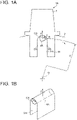
FIG. 1A is a schematic front view of a main portion of a rotor assembly according to an embodiment not making part of the present invention but useful to its understanding. -
FIG. 1B is a perspective view of a rolling element which rolls on the curved surface shown inFIG. 1A . -
FIG. 2A is a schematic front view of a main portion of a rotor assembly according to an embodiment not making part of the present invention but useful to its understanding. -
FIG. 2B is a perspective view of a rolling element which rolls on the curved surface shown inFIG. 2A . -
FIG. 3A is a schematic front view of a main portion of a rotor assembly according to an embodiment of the present invention. -
FIG. 3B is a perspective view of a rolling element which rolls on the curved surface shown inFIG. 3A . -
FIG. 4A is a schematic front view of a main portion of a rotor assembly according to an embodiment not making part of the present invention but useful to its understanding. -
FIG. 4B is a perspective view of a rolling element which rolls on the curved surface shown inFIG. 4A . -
FIG. 5A is a schematic front view of a main portion of a rotor assembly according to an embodiment not making part of the present invention but useful to its understanding. -
FIG. 5B is a perspective view of a rolling element which rolls on the curved surface shown inFIG. 5A . -
FIG. 6A is a schematic front view of a main portion of a rotor assembly according to an embodiment of the present invention. -
FIG. 6B is a perspective view of a rolling element which rolls on the curved surface shown inFIG. 6A . -
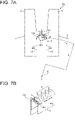
FIG. 7A is a schematic front view of a main portion of a rotor assembly according to an embodiment not making part of the present invention but useful to its understanding. -
FIG. 7B is a perspective view of a rolling element which rolls on the curved surface shown inFIG. 7A . -
FIG. 8A is a Campbell diagram of the rotor assembly shown inFIG. 2 . -
FIG. 8B is an order analysis diagram of the rotor assembly shown inFIG. 2 . -
FIG. 9 is a Campbell diagram of the rotor assembly shown inFIG. 4 . -
FIG. 10A is a diagram showing the U-shaped plate spring and the rolling element shown inFIGs. 2 to 7 before the U-shaped plate spring is elastically deformed. -
FIG. 10B is a diagram showing the U-shaped plate spring and the rolling element shown inFIGs. 2 to 7 after the U-shaped plate spring is elastically deformed. -
FIG. 11 is a schematic diagram of a rotating machine according to an embodiment of the present invention. - Embodiments of the present invention will now be described in detail with reference to the accompanying drawings. It is intended, however, that unless particularly identified, dimensions, materials, shapes, relative positions, and the like of components described in the embodiments shall be interpreted as illustrative only and not intended to limit the scope of the present invention. The present invention is defined in the appended set of claims.
- For instance, an expression of relative or absolute arrangement such as "in a direction", "along a direction", "parallel", "orthogonal", "centered", "concentric" and "coaxial" shall not be construed as indicating only the arrangement in a strict literal sense, but also includes a state where the arrangement is relatively displaced by a tolerance, or by an angle or a distance whereby it is possible to achieve the same function.
- Further, for instance, an expression of a shape such as a rectangular shape or a cylindrical shape shall not be construed as only the geometrically strict shape, but also includes a shape with unevenness or chamfered corners within the range in which the same effect can be achieved.
- On the other hand, an expression such as "comprise", "include", "have", "contain" and "constitute" are not intended to be exclusive of other components.
-
FIGs. 1 to 7 are schematic front views of a main portion of arotor assembly FIG. 8A is a Campbell diagram of therotor assembly 1B shown inFIG. 2 .FIG. 8B is an order analysis diagram of therotor assembly 1B shown inFIG. 2 .FIG. 9 is a Campbell diagram of therotor assembly 1C shown inFIG. 4 .FIGs. 10 are diagrams showing theU-shaped plate spring 5 and the rollingelement FIGs. 2 to 7 .FIG. 11 is a schematic diagram of a rotating machine according to an embodiment of the present invention. - The
rotor assembly FIG. 11 ), such as a gas turbine (seeFIG. 11 ), a steam turbine, or a jet engine. - As shown in
FIGs. 1 to 7 , therotor assembly rotor disc 2, a plurality ofrotor blades 3, and at least one rollingelement - The
rotor disc 2 is supported rotatably around the central axis O of therotor assembly rotor blades 3 are fixed to therotor disc 2 and extend radially outward in a direction away from the central axis O (hereinafter, referred to as "radial direction") in a plane perpendicular to the central axis O of therotor disc 2. The at least one rollingelement rotor disc 2. - With the
rotor assembly rotor assembly element element rotor disc 2, and when therotor blade 3 vibrates, the rollingelement element rotor assembly rotor blade 3 is damped on the excitation harmonic (seeFIGs. 8A and9 ). As a result, therotor assembly rotor blade 3 at the natural frequency corresponding to the rotational speed of therotor assembly - For example, as shown in
FIGs. 8A and9 , in order to deal with 4N excitation harmonic, the constant C of fn = C×Ω may be set to 4. In this case, when the rotational speed of therotor assembly rotor assembly rotor blade 3 at the natural frequency corresponding to each rotational speed can be reduced. - As shown in
FIGs. 1 to 7 , in therotor assembly element rotor disc 2. The rollingelement rotor disc 2 is, for example, a tubular member of tubular shape, a cylindrical member of cylindrical shape, or a spherical member of spherical shape. The tubular member and the cylindrical member are arranged such that their central axis is oriented along the central axis O of therotor disc 2, for example. - With the
rotor assembly element rotor disc 2, therotor assembly rotor blade 3 at the natural frequency corresponding to the rotational speed of therotor disc 2. - As shown in
FIGs. 1 to 7 , in therotor assembly element - With the
rotor assembly element expression 3.
element rotor disc 2. - Accordingly, when the constant C expressed by the following expression 4 is set to an integer-multiple order of excitation harmonic, the vibration of the
rotor blade 3 is damped on the excitation harmonic (seesFIG. 8A and9 ).
- As a result, the
rotor assembly rotor blade 3 at the natural frequency corresponding to the rotational speed of therotor assembly - As shown in
FIGs. 1 to 7 , in therotor assembly rotor disc 2 are provided on both sides of the curved surface CS having a constant curvature radius. - With the
rotor assembly rotor assembly element element rotor blade 3 vibrates, the rollingelement element - As shown in
FIGs. 3 to 6 , in therotor assembly element first rolling element second rolling element first rolling element second rolling element - In this case, the first curved surface CS1, the second curved surface CS2, the
first rolling element second rolling element - (A) the first curvature radius R1 of the first curved surface CS1 is different from the second curvature radius R2 of the second curved surface CS2;
- (B) the first radius r1 of the
first rolling element second rolling element - (C) the distance d1 from the central axis O of the
rotor disc 2 to thefirst rolling element rotor disc 2 to thesecond rolling element - As shown in
FIG. 9 , with therotor assembly first rolling element second rolling element rotor blade 3 is damped on the excitation harmonics of different integer-multiple orders. As a result, therotor assembly rotor blade 3 at the natural frequency corresponding to the rotational speed of therotor assembly - According to the invention, as shown in
FIG. 3 , the first curvature radius R1 of the first curved surface CS1 is different from the second curvature radius R2 of the second curved surface CS2. - For example, the first curvature radius R1 of the first curved surface CS1 is set such that the constant C1 in the expression fn1 = C1×Ω representing the rolling frequency of the
first rolling element 41C is 4, and the second curvature radius R2 of the second curved surface CS2 is set such that the constant C2 in the expression fn2 = C2×Ω representing the rolling frequency of thesecond rolling element 42C is 2. In this case, when the rotational speed of therotor assembly 1C is Ω11, the 4N excitation harmonic intersects the natural frequency f11 of the first mode, and when the rotational speed of therotor assembly 1C is Ω12, the 4N excitation harmonic intersects the natural frequency f12 of the second mode. In addition, when the rotational speed of therotor assembly 1C is Ω21, the 2N excitation harmonic intersects the natural frequency f21 (f11) of the first mode. - Thus, when the first curvature radius R1 of the first curved surface CS1 is set such that the constant C1 is 4 while the second curvature radius R2 of the second curved surface CS2 is set such that the constant C2 is 2, fn=f11 at Ω11, fn=f12 at Ω12, and fn=f21 at Ω21, so that the vibration of the
rotor blade 3 at the natural frequency corresponding to each rotational speed can be reduced. - For example, in the
rotor assembly 1D shown inFIG. 4 , the first radius r1 of thefirst rolling element 41D is different from the second radius r2 of thesecond rolling element 42D. - For example, the first radius r1 of the
first rolling element 41D is set such that the constant C1 in the expression fn1 = C1×Ω representing the rolling frequency of thefirst rolling element 41D is 4, and the second radius r2 of thesecond rolling element 42D is set such that the constant C2 in the expression fn2 = C2×Ω representing the rolling frequency of thesecond rolling element 42D is 2. In this case, as shown inFIG. 9 , when the rotational speed of therotor assembly 1D is Ω11, the 4N excitation harmonic intersects the natural frequency f11 of the first mode, and when the rotational speed of therotor assembly 1D is Ω12, the 4N excitation harmonic intersects the natural frequency f12 of the second mode. In addition, when the rotational speed of therotor assembly 1D is Ω21, the 2N excitation harmonic intersects the natural frequency f21 (f11) of the first mode. - Thus, when the first radius r1 of the
first rolling element 41D is set such that the constant C1 is 4 while the second radius r2 of thesecond rolling element 42D is set such that the constant C2 is 2, fn=f11 at Ω11, fn=f12 at Ω12, and fn=f21 at Ω21, so that the vibration of therotor blade 3 at the natural frequency corresponding to each rotational speed can be reduced. - For example, in the
rotor assembly 1E shown inFIG. 5 , the distance d1 from the central axis O of therotor disc 2 to thefirst rolling element 41E different from the distance d2 from the central axis O of therotor disc 2 to thesecond rolling element 42E. - For example, the distance d1 from the central axis O of the
rotor disc 2 to thefirst rolling element 41E is set such that the constant C1 in the expression fn1 = C1×Ω representing the rolling frequency of thefirst rolling element 41E is 4, and the distance d2 from the central axis O of therotor disc 2 to thesecond rolling element 42E is set such that the constant C2 in the expression fn2 = C2×Ω representing the rolling frequency of thesecond rolling element 42E is 2. In this case, when the rotational speed of therotor assembly 1E is Ω11, the 4N excitation harmonic intersects the natural frequency f11 of the first mode, and when the rotational speed of therotor assembly 1E is Ω12, the 4N excitation harmonic intersects the natural frequency f12 of the second mode. In addition, when the rotational speed of therotor assembly 1E is Ω21, the 2N excitation harmonic intersects the natural frequency f21 (f11) of the first mode. - Thus, when the distance d1 from the central axis O of the
rotor disc 2 to thefirst rolling element 41E is set such that C1 is 4 while the distance d2 from the central axis O of therotor disc 2 to thesecond rolling element 42E is set such that the constant C2 is 2, fn=f11 at Ω11, fn=f12 at Ω12, and fn=f21 at Ω21, so that the vibration of therotor blade 3 at the natural frequency corresponding to each rotational speed can be reduced. - According to the invention, in the
rotor assembly 1F shown inFIG. 6 , two ((A) and (B)) of the following conditions (A) to (C) are satisfied: - (A) the first curvature radius R1 of the first curved surface CS1 is different from the second curvature radius R2 of the second curved surface CS2;
- (B) the first radius r1 of the
first rolling element 41F is different from the second radius r2 of thesecond rolling element 42F; or - (C) the distance d1 from the central axis O of the
rotor disc 2 to thefirst rolling element 41F is different from the distance d2 from the central axis O of therotor disc 2 to thesecond rolling element 42F. - For example, the first curvature radius R1 of the first curved surface CS1 and the first radius r1 of the
first rolling element 41F are set such that the constant C1 in the expression fn1 = C1×Ω representing the rolling frequency of thefirst rolling element 41F is 4. Further, the second curvature radius R2 of the second curved surface CS2 and the second radius r2 of thesecond rolling element 42F are set such that the constant C2 in the expression fn2 = C2×Ω representing the rolling frequency of thesecond rolling element 42F is 2. In this case, when the rotational speed of therotor assembly 1F is Ω11, the 4N excitation harmonic intersects the natural frequency f11 of the first mode, and when the rotational speed of therotor assembly 1F is Ω12, the 4N excitation harmonic intersects the natural frequency f12 of the second mode. In addition, when the rotational speed of therotor assembly 1F is Ω21, the 2N excitation harmonic intersects the natural frequency f21 (f11) of the first mode. - Thus, when the first curvature radius R1 of the first curved surface CS1 and the first radius r1 of the
first rolling element 41F are set such that the constant C1 in the expression fn1 = C1×Ω representing the rolling frequency of thefirst rolling element 41F is 4 while the second curvature radius R2 of the second curved surface CS2 and the second radius r2 of thesecond rolling element 42F are set such that the constant C2 in the expression fn2 = C2×Ω representing the rolling frequency of thesecond rolling element 42F is 2, fn=f11 at Ω11, fn=f12 at Ω12, and fn=f21 at Ω21, so that the vibration of therotor blade 3 at the natural frequency corresponding to each rotational speed can be reduced. - As shown in
FIGs. 3 to 6 , in therotor assembly first rolling element second rolling element rotor disc 2. - With the
rotor assembly first rolling element second rolling element rotor blade 3 is damped on the excitation harmonics of different integer-multiple orders. As a result, therotor assembly rotor blade 3 at the natural frequency corresponding to the rotational speed of therotor assembly - As shown in
FIGs. 1 to 6 , in therotor assembly element - With the
rotor assembly rotor assembly element element rotor disc 2, and when therotor blade 3 vibrates, the rollingelement - As shown in
FIG. 7 , in therotor assembly 1G according to embodiments not making part of the present invention but useful to its understanding, the rollingelement 4G is a plurality of spherical members. - With the
rotor assembly 1G according to embodiments not making part of the present invention but useful to its understanding, as therotor assembly 1G rotates, the centrifugal force F acts on the rollingelements 4G. Due to the action of the centrifugal force F, the rollingelements 4G are pressed against the curved surface CS facing inward in the radial direction of therotor disc 2, and when therotor blade 3 vibrates, the rollingelements 4G roll on the curved surface CS, and the rollingelements 4G collide with each other. The collision of the rollingelements 4G reduces the vibration of therotor blade 3. - As shown in
FIGs. 2 to 7 , in therotor assembly U-shaped plate spring 5 disposed between therotor blades 3 which are adjacent in the circumferential direction of therotor disc 2. TheU-shaped plate spring 5 has a U-shaped opening facing inward in the radial direction of therotor disc 2. - With the
rotor assembly U-shaped plate spring 5 and therotor blade 3 to damp the vibration occurring in therotor blade 3. As a result, therotor assembly rotor blade 3. - As shown in
FIG. 10 , in therotor assembly U-shaped plate spring 5 has acurved portion 51 whose inner side forms the curved surface CS andleg portions leg portions U-shaped plate spring 5 extend more than the distance between therotor blades 3 adjacent in the circumferential direction of the rotor disc 2 (seeFIG. 10A ), and theU-shaped plate spring 5 is mounted between therotor blades 3 adjacent in the circumferential direction of therotor disc 2 in a state where theleg portions FIG. 10B ). - With the
rotor assembly leg portions U-shaped plate spring 5 so as to return to the original shape, and the frictional force acts between eachleg portion 52, 53 (outer wall surface) of theU-shaped plate spring 5 and therotor blade 3 to damp the vibration occurring in therotor blade 3. As a result, therotor assembly rotor blade 3. - As shown in
FIG. 1 , therotor assembly 1A, according to embodiments not making part of the present invention but useful to its understanding, includes therotor disc 2, the plurality ofrotor blades 3, and the rollingelement 4A. Therotor disc 2 is supported rotatably around the central axis O of therotor assembly 1A. Therotor blades 3 are fixed to therotor disc 2 and extend radially outward in the radial direction of therotor disc 2. The rollingelement 4A is configured to roll on the curved surface CS facing inward in the radial direction of therotor disc 2. - The curved surface CS facing inward in the radial direction of the
rotor disc 2 is provided on afixation portion 31 of therotor blade 3 to therotor disc 2. The curved surface CS constitutes a part of acavity 311 provided in thefixation portion 31 of therotor blade 3 to therotor disc 2. Thecavity 311 is provided along the radial direction of therotor disc 2, and the curved surface CS is provided on the side facing inward in the radial direction of therotor disc 2. The curved surface CS has a constant curvature radius R, and side surfaces SD extending along the radial direction of therotor disc 2 are provided on both sides of the curved surface CS having the constant curvature radius R. Thus, the pair of side surface SD delimits the curved surface CS to define the curved surface CS. - The rolling
element 4A has a circular outer shape in a cross-section perpendicular to the direction along the central axis O of therotor disc 2, and is a tubular member or a cylindrical member having a radius r smaller than the curvature radius R of the curved surface CS. - With the
rotor assembly 1A according to embodiments not making part of the present invention but useful to its understanding, as therotor assembly 1A rotates, the centrifugal force F acts on the rollingelements 4A. Due to the action of the centrifugal force F, the rollingelement 4A is pressed against the curved surface CS facing inward in the radial direction of therotor disc 2, and when therotor blade 3 vibrates, the rollingelement 4A rolls on the curved surface CS. Since the rolling frequency fn of the rollingelement 4A is proportional to the rotational speed of therotor assembly 1A (fn = C×Ω), when the constant C is set to an integer-multiple order of excitation harmonic, the vibration of therotor blade 3 is damped on the excitation harmonic. As a result, therotor assembly 1A can reduce the vibration of therotor blade 3 at the natural frequency corresponding to the rotational speed of therotor assembly 1A. - As shown in
FIG. 2 , therotor assembly 1B according to embodiments not making part of the present invention but useful to its understanding, includes therotor disc 2, the plurality ofrotor blades 3, and the rollingelement 4B. Therotor disc 2 is supported rotatably around the central axis O of therotor assembly 1B. Therotor blades 3 are fixed to therotor disc 2 and extend radially outward in the radial direction of therotor disc 2. The rollingelement 4B is configured to roll on the curved surface CS facing inward in the radial direction of therotor disc 2. - The curved surface CS facing inward in the radial direction of the
rotor disc 2 is provided on aU-shaped plate spring 5 mounted between therotor blades 3 which are adjacent in the circumferential direction of therotor disc 2. TheU-shaped plate spring 5 has a U-shaped opening facing inward in the radial direction of therotor disc 2. TheU-shaped plate spring 5 has acurved portion 51 facing inward in the radial direction of therotor disc 2 andleg portions leg portions U-shaped plate spring 5 extend more than the distance between therotor blades 3 adjacent in the circumferential direction of therotor disc 2, and theU-shaped plate spring 5 is mounted between therotor blades 3 adjacent in the circumferential direction of therotor disc 2 in a state where theleg portions U-shaped plate spring 5 mounted in this way has a constant curvature radius R (seeFIG. 2A ). - As shown in
FIG. 2 , the rollingelement 4B has a circular outer shape in a cross-section perpendicular to the direction along the central axis O of therotor disc 2, and is a tubular member or a cylindrical member having a radius r smaller than the constant curvature radius R of the curved surface CS. - With the
rotor assembly 1B according to the above-described embodiments, the elastic restoring force acts on theleg portions U-shaped plate spring 5 so as to return to the original shape, and the frictional force acts between eachleg portion 52, 53 (outer wall surface) of theU-shaped plate spring 5 and therotor blade 3 to damp the vibration occurring in the rotor blade 3 (see the dotted line in the order analysis diagram ofFIG. 8B ). Further, as therotor assembly 1B rotates, the centrifugal force F acts on the rollingelement 4B. Due to the action of the centrifugal force F, the rollingelement 4B is pressed against the curved surface CS facing inward in the radial direction of therotor disc 2, and when therotor blade 3 vibrates, the rollingelement 4B rolls on the curved surface CS. Since the rolling frequency fn of the rollingelement 4B is proportional to the rotational speed of therotor assembly 1B (fn = C×Ω), when the constant C is set to an integer-multiple order of excitation harmonic, the vibration of therotor blade 3 is damped on the excitation harmonic (see the dotted line in the order analysis diagram ofFIG. 8B ). As a result, the vibration of therotor blade 3 is synergistically damped, so that a larger damping effect can be obtained. - As shown in
FIG. 3 , therotor assembly 1C according to some embodiments of the present invention includes therotor disc 2, the plurality ofrotor blades 3, and at least one rollingelement 4C. Therotor disc 2 is supported rotatably around the central axis O of therotor assembly 1C. Therotor blades 3 are fixed to therotor disc 2 and extend radially outward in the radial direction of therotor disc 2. The at least one rollingelement 4C is configured to roll on the curved surface CS facing inward in the radial direction of therotor disc 2. - The curved surface CS facing inward in the radial direction of the
rotor disc 2 is provided on aU-shaped plate spring 5 mounted between therotor blades 3 which are adjacent in the circumferential direction of therotor disc 2. TheU-shaped plate spring 5 has a U-shaped opening facing inward in the radial direction of therotor disc 2. TheU-shaped plate spring 5 includes a first U-shaped plate spring 5C1 and a second U-shaped plate spring 5C2. The first U-shaped plate spring 5C1 has a first curved surface CS1 as the curved surface CS, and the second U-shaped plate spring 5C2 has a second curved surface CS2 as the curved surface CS. - The first U-shaped plate spring 5C1 has a curved portion 5C11 having a U-shaped opening facing inward in the radial direction of the
rotor disc 2 and leg portions 5C12, 5C13 having side surfaces SD provided on both sides of the first curved surface CS1. The leg portions 5C12, 5C13 of the first U-shaped plate spring 5C1 extend more than the distance between therotor blades 3 adjacent in the circumferential direction of therotor disc 2, and the first U-shaped plate spring 5C1 is mounted between therotor blades 3 adjacent in the circumferential direction of therotor disc 2 in a state where the leg portions 5C12, 5C13 are contracted (elastically deformed). The first curved surface CS1 of the first U-shaped plate spring 5C1 mounted in this way has a constant curvature radius R1. - As with the first U-shaped plate spring 5C1, the second U-shaped plate spring 5C2 has a curved portion 5C21 having a U-shaped opening facing inward in the radial direction of the
rotor disc 2 and leg portions 5C22, 5C23 having side surfaces SD provided on both sides of the second curved surface CS2. The leg portions 5C22, 5C23 of the second U-shaped plate spring 5C2 extend more than the distance between therotor blades 3 adjacent in the circumferential direction of therotor disc 2, and the second U-shaped plate spring 5C2 is mounted between therotor blades 3 adjacent in the circumferential direction of therotor disc 2 in a state where the leg portions 5C22, 5C23 are contracted (elastically deformed). The second curved surface CS2 of the second U-shaped plate spring 5C2 mounted in this way has a constant curvature radius R2. - The first curvature radius R1 of the first curved surface CS1 of the first U-shaped plate spring 5C1 is different from the second curvature radius R2 of the second curved surface CS2 of the second U-shaped plate spring 5C2. The first U-shaped plate spring 5C1 and the second U-shaped plate spring 5C2 are disposed at different positions in the direction along the central axis O of the
rotor disc 2. - The rolling
element 4C has a circular outer shape in a cross-section perpendicular to the direction along the central axis O of therotor disc 2, and is a tubular member or a cylindrical member having a radius r smaller than the constant curvature radius R of the curved surface CS. The rollingelement 4C includes afirst rolling element 41C and asecond rolling element 42C. The radius r of thefirst rolling element 41C is equal to the radius r of thesecond rolling element 42C, and thefirst rolling element 41C and thesecond rolling element 42C are disposed at different positions in the direction along the central axis O of therotor disc 2. - For example, the first curvature radius R1 of the first curved surface CS1 is set such that the constant C1 in the expression fn1 = C1×Ω representing the rolling frequency of the
first rolling element 41C is 4, and the second curvature radius R2 of the second curved surface CS2 is set such that the constant C2 in the expression fn2 = C2×Ω representing the rolling frequency of thesecond rolling element 42C is 2. In this case, as shown inFIG. 9 , when the rotational speed of therotor assembly 1C is Ω11, the 4N excitation harmonic intersects the natural frequency f11 of the first mode, and when the rotational speed of therotor assembly 1C is Ω12, the 4N excitation harmonic intersects the natural frequency f12 of the second mode. In addition, when the rotational speed of therotor assembly 1C is Ω21, the 2N excitation harmonic intersects the natural frequency f21 (f11) of the first mode. - Thus, when the first curvature radius R1 of the first curved surface CS1 is set such that the constant C1 is 4 while the second curvature radius R2 of the second curved surface CS2 is set such that the constant C2 is 2, fn=f11 at Ω11, fn=f12 at Ω12, and fn=f21 at Ω21, so that the vibration of the
rotor blade 3 at the natural frequency corresponding to each rotational speed can be reduced. - With the
rotor assembly 1C according to the above-described embodiments, the elastic restoring force acts on the leg portions 5C12, 5C13 of the first U-shaped plate spring 5C1 and the leg portions 5C22, 5C23 of the second U-shaped plate spring 5C2 so as to return to the original shape. Thus, the frictional force acts between each leg portion 5C12, 5C13 (outer wall surface) of the first U-shaped plate spring 5C1 and therotor blade 3, as well as between each leg portion 5C22, 5C23 (outer wall surface) of the second U-shaped plate spring 5C2 and therotor blade 3, to damp the vibration occurring in therotor blade 3. - Further, as the
rotor assembly 1C rotates, the centrifugal force F acts on thefirst rolling element 41C and thesecond rolling element 42C. Due to the action of the centrifugal force F, thefirst rolling element 41C is pressed against the first curved surface CS1, and thesecond rolling element 42C is pressed against the second curved surface CS2. Thus, when therotor blade 3 vibrates, thefirst rolling element 41C rolls on the first curved surface CS1, and thesecond rolling element 42C rolls on the second curved surface CS2. Since the rolling frequency fn of thefirst rolling element 41C and the rolling frequency fn of thesecond rolling element 42C are proportional to the rotational speed of therotor assembly 1C (fn = C×Ω), when the constant C is set to an integer-multiple order of excitation harmonic, the vibration of therotor blade 3 is damped on the excitation harmonic. As a result, the vibration of therotor blade 3 is synergistically damped, so that a larger damping effect can be obtained. - Further, the integer-multiple orders of excitation harmonics of the
first rolling element 41C and thesecond rolling element 42C can be made different by the curvature radius R1 of the first curved surface CS1 and the curvature radius R2 of the second curved surface CS2. Thus, since the integer-multiple orders of excitation harmonics are different, the vibration of therotor blade 3 is damped on the excitation harmonics of different integer-multiple orders. As a result, therotor assembly 1C can reduce the vibration of therotor blade 3 at the natural frequency corresponding to the rotational speed of therotor assembly 1C on the excitation harmonics of different integer-multiple orders. - As shown in
FIG. 4 , therotor assembly 1D according to embodiments not making part of the present invention but useful to its understanding, includes therotor disc 2, the plurality ofrotor blades 3, and at least one rollingelement 4D. Therotor disc 2 is supported rotatably around the central axis O of therotor assembly 1D. Therotor blades 3 are fixed to therotor disc 2 and extend radially outward in the radial direction of therotor disc 2. The at least one rollingelement 4D is configured to roll on the curved surface CS facing inward in the radial direction of therotor disc 2. - The curved surface CS facing inward in the radial direction of the
rotor disc 2 is provided on aU-shaped plate spring 5 mounted between therotor blades 3 which are adjacent in the circumferential direction of therotor disc 2. TheU-shaped plate spring 5 has a U-shaped opening facing inward in the radial direction of therotor disc 2. TheU-shaped plate spring 5 has acurved portion 51 facing inward in the radial direction of therotor disc 2 andleg portions leg portions U-shaped plate spring 5 extend more than the distance between therotor blades 3 adjacent in the circumferential direction of therotor disc 2, and theU-shaped plate spring 5 is mounted between therotor blades 3 adjacent in the circumferential direction of therotor disc 2 in a state where theleg portions U-shaped plate spring 5 mounted in this way has a constant curvature radius R. - The rolling
element 4D has a circular outer shape in a cross-section perpendicular to the direction along the central axis O of therotor disc 2, and is a tubular member or a cylindrical member having a radius r smaller than the constant curvature radius R of the curved surface CS. The rollingelement 4D includes afirst rolling element 41D and asecond rolling element 42D. The first radius r1 of thefirst rolling element 41D is different from the second radius r2 of thesecond rolling element 42D. Thefirst rolling element 41D and thesecond rolling element 42D are disposed at different positions in the direction along the central axis O of therotor disc 2. - For example, the first radius r1 of the
first rolling element 41D is set such that the constant C1 in the expression fn1 = C1×Ω representing the rolling frequency of thefirst rolling element 41D is 4, and the second radius r2 of thesecond rolling element 42D is set such that the constant C2 in the expression fn = C2×Ω representing the rolling frequency of thesecond rolling element 42D is 2. In this case, as shown inFIG. 9 , when the rotational speed of therotor assembly 1D is Ω11, the 4N excitation harmonic intersects the natural frequency f11 of the first mode, and when the rotational speed of therotor assembly 1D is Ω12, the 4N excitation harmonic intersects the natural frequency f12 of the second mode. In addition, when the rotational speed of therotor assembly 1D is Ω21, the 2N excitation harmonic intersects the natural frequency f21 (f11) of the first mode. - Thus, when the first radius r1 of the
first rolling element 41D is set such that the constant C1 in the expression fn1 = C1×Ω representing the rolling frequency of thefirst rolling element 41D is 4 while the second radius r2 of thesecond rolling element 42D is set such that the constant C2 in the expression fn2 = C2×Ω representing the rolling frequency of thesecond rolling element 42D is 2, fn=f11 at Ω11, fn=f12 at Ω12, and fn=f21 at Ω21, so that the vibration of therotor blade 3 at the natural frequency corresponding to each rotational speed can be reduced. - With the
rotor assembly 1D according to the above-described embodiments, the elastic restoring force acts on theleg portions U-shaped plate spring 5 so as to return to the original shape, and the frictional force acts between eachleg portion 52, 53 (outer side surface) of theU-shaped plate spring 5 and therotor blade 3 to damp the vibration occurring in therotor blade 3. Further, as therotor assembly 1D rotates, the centrifugal force F acts on thefirst rolling element 41D and thesecond rolling element 42D. Due to the action of the centrifugal force F, thefirst rolling element 41D and thesecond rolling element 42D are pressed against the curved surface CS facing inward in the radial direction of therotor disc 2, and when therotor blade 3 vibrates, thefirst rolling element 41D and thesecond rolling element 42D roll on the curved surface CS. Since the rolling frequencies fn of thefirst rolling element 41D and thesecond rolling element 42D are proportional to the rotational speed of therotor assembly 1D (fn = C×Ω), when the constant C is set to an integer-multiple order of excitation harmonic, the vibration of therotor blade 3 is damped on the excitation harmonic. As a result, the vibration of therotor blade 3 is synergistically damped, so that a larger damping effect can be obtained. - Further, the integer-multiple orders of excitation harmonics of the
first rolling element 41D and thesecond rolling element 42D can be made different by the first radius r1 of thefirst rolling element 41D and the second radius r2 of thesecond rolling element 42D. Thus, since the integer-multiple orders of excitation harmonics are different, the vibration of therotor blade 3 is damped on the excitation harmonics of different integer-multiple orders. As a result, therotor assembly 1D can reduce the vibration of therotor blade 3 at the natural frequency corresponding to the rotational speed of therotor assembly 1D on the excitation harmonics of different integer-multiple orders. - As shown in
FIG. 5 , therotor assembly 1E according to embodiments not making part of the present invention but useful to its understanding, includes therotor disc 2, the plurality ofrotor blades 3, and at least one rollingelement 4E. Therotor disc 2 is supported rotatably around the central axis O of therotor assembly 1E. Therotor blades 3 are fixed to therotor disc 2 and extend radially outward in the radial direction of therotor disc 2. The at least one rollingelement 4E is configured to roll on the curved surface CS facing inward in the radial direction of therotor disc 2. - The curved surface CS facing inward in the radial direction of the
rotor disc 2 is provided on aU-shaped plate spring 5 mounted betweenadjacent rotor blades 3 of therotor disc 2. TheU-shaped plate spring 5 has a U-shaped opening facing inward in the radial direction of therotor disc 2. TheU-shaped plate spring 5 includes a first U-shaped plate spring 5E1 and a second U-shaped plate spring 5E2. The first U-shaped plate spring 5E1 has a first curved surface CS1 as the curved surface CS, and the second U-shaped plate spring 5E2 has a second curved surface CS2 as the curved surface CS. - The first U-shaped plate spring 5E1 has a curved portion 5E11 having a U-shaped opening facing inward in the radial direction of the
rotor disc 2 and leg portions 5E12, 5E13 having side surfaces SD provided on both sides of the first curved surface CS1. The leg portions 5E12, 5E13 of the first U-shaped plate spring 5E1 extend more than the distance between therotor blades 3 adjacent in the circumferential direction of therotor disc 2, and the first U-shaped plate spring 5E1 is mounted between therotor blades 3 adjacent in the circumferential direction of therotor disc 2 in a state where the leg portions 5E12, 5E13 are contracted (elastically deformed). The first curved surface CS1 of the first U-shaped plate spring 5E1 mounted in this way has a constant curvature radius R. - As with the first U-shaped plate spring 5E1, the second U-shaped plate spring 5E2 has a curved portion 5E21 having a U-shaped opening facing inward in the radial direction of the
rotor disc 2 and leg portions 5E22, 5E23 having side surfaces SD provided on both sides of the second curved surface CS2. The leg portions 5E22, 5E23 of the second U-shaped plate spring 5E2 extend more than the distance between therotor blades 3 adjacent in the circumferential direction of therotor disc 2, and the second U-shaped plate spring 5E2 is mounted between therotor blades 3 adjacent in the circumferential direction of therotor disc 2 in a state where the leg portions 5E22, 5E23 are contracted (elastically deformed). The second curved surface CS2 of the second U-shaped plate spring 5E2 mounted in this way has a constant curvature radius R. - The first curvature radius R1 of the first curved surface CS1 of the first U-shaped plate spring 5E1 is equal to the second curvature radius R2 of the second curved surface CS2 of the second U-shaped plate spring 5E2, but the first U-shaped plate spring 5E1 and the second U-shaped plate spring 5E2 are disposed at different positions in the direction along the central axis O of the
rotor disc 2. - For arranging the first U-shaped plate spring 5E1 and the second U-shaped plate spring 5E2, for instance, stepped portions with different radii in the radial direction of the
rotor disc 2 may be arranged in the direction along the central axis O of therotor disc 2. - The rolling
element 4E has a circular outer shape in a cross-section perpendicular to the direction along the central axis O of therotor disc 2, and is a tubular member or a cylindrical member having a radius r smaller than the constant curvature radius R of the curved surface CS. The rollingelement 4E includes afirst rolling element 41E and asecond rolling element 42E. The first radius r1 of thefirst rolling element 41E is equal to the second radius r2 of thesecond rolling element 42E, but thefirst rolling element 41E and thesecond rolling element 42E are disposed at different position in the direction along the central axis O of therotor disc 2. - For example, the distance d1 from the central axis O of the
rotor disc 2 to the first curved surface CS1 is set such that the constant C1 in the expression fn1 = C1×Ω representing the rolling frequency of thefirst rolling element 41E is 4, and the distance d2 from the central axis O of therotor disc 2 to the second curved surface CS2 is set such that the constant C2 in the expression fn2 = C2×Ω representing the rolling frequency of thesecond rolling element 42E is 2. In this case, when the rotational speed of therotor assembly 1E is Ω11, the 4N excitation harmonic intersects the natural frequency f11 of the first mode, and when the rotational speed of therotor assembly 1E is Ω12, the 4N excitation harmonic intersects the natural frequency f12 of the second mode. In addition, when the rotational speed of therotor assembly 1E is Ω21, the 2N excitation harmonic intersects the natural frequency f21 (f11) of the first mode. - Thus, when the distance d1 from the central axis O of the
rotor disc 2 to the first curved surface CS1 is set such that C1 is 4 while the distance d2 from the central axis O of therotor disc 2 to the second curved surface CS2 is set such that the constant C2 in the expression fn2 = C2×Ω representing the rolling frequency of thesecond rolling element 42E is 2, fn=f11 at Ω11, fn=f12 at Ω12, and fn=f21 at Ω21, so that the vibration of therotor blade 3 at the natural frequency corresponding to each rotational speed can be reduced. - With the
rotor assembly 1E according to the above-described embodiments, the elastic restoring force acts on the leg portions 5E12, 5E13 of the first U-shaped plate spring 5E1 and the leg portions 5E22, 5E23 of the second U-shaped plate spring 5E2 so as to return to the original shape. Thus, the frictional force acts between each leg portion 5E12, 5E13 (outer wall surface) of the first U-shaped plate spring 5E1 and therotor blade 3, as well as between each leg portion 5E22, 5E23 (outer wall surface) of the second U-shaped plate spring 5E2 and therotor blade 3, to damp the vibration occurring in therotor blade 3. - Further, as the
rotor assembly 1E rotates, the centrifugal force F acts on thefirst rolling element 41E and thesecond rolling element 42E. Due to the action of the centrifugal force F, thefirst rolling element 41E is pressed against the first curved surface CS1, and thesecond rolling element 42E is pressed against the second curved surface CS2. Thus, when therotor blade 3 vibrates, thefirst rolling element 41E rolls on the first curved surface CS1, and thesecond rolling element 42E rolls on the second curved surface CS2. Since the rolling frequency fn of thefirst rolling element 41E and the rolling frequency fn of thesecond rolling element 42E are proportional to the rotational speed of therotor assembly 1E (fn = C×Ω), when the constant C is set to an integer-multiple order of excitation harmonic, the vibration of therotor blade 3 is damped on the excitation harmonic. As a result, the vibration of therotor blade 3 is synergistically damped, so that a larger damping effect can be obtained. - Further, the integer-multiple orders of excitation harmonics of the
first rolling element 41E and thesecond rolling element 42E can be made different by the distance d1 from the central axis O of therotor disc 2 to thefirst rolling element 41E and the distance d2 from the central axis O of therotor disc 2 to thesecond rolling element 42E. Thus, since the integer-multiple orders of excitation harmonics are different, the vibration of therotor blade 3 is damped on the excitation harmonics of different integer-multiple orders. As a result, therotor assembly 1E can reduce the vibration of therotor blade 3 at the natural frequency corresponding to the rotational speed of therotor assembly 1E on the excitation harmonics of different integer-multiple orders. - As shown in
FIG. 6 , therotor assembly 1F according to some embodiments of the present invention includes therotor disc 2, the plurality ofrotor blades 3, and at least one rollingelement 4F. Therotor disc 2 is supported rotatably around the central axis O of therotor assembly 1F. Therotor blades 3 are fixed to therotor disc 2 and extend radially outward in the radial direction of therotor disc 2. The at least one rollingelement 4F is configured to roll on the curved surface CS facing inward in the radial direction of therotor disc 2. - The curved surface CS facing inward in the radial direction of the
rotor disc 2 is provided on aU-shaped plate spring 5 mounted betweenadjacent rotor blades 3 of therotor disc 2. TheU-shaped plate spring 5 has a U-shaped opening facing inward in the radial direction of therotor disc 2. TheU-shaped plate spring 5 includes a first U-shaped plate spring 5F1 and a second U-shaped plate spring 5F2. The first U-shaped plate spring 5F1 has a first curved surface CS1 as the curved surface CS, and the second U-shaped plate spring 5F2 has a second curved surface CS2 as the curved surface CS. - The first U-shaped plate spring 5F1 has a curved portion 5F11 having a U-shaped opening facing inward in the radial direction of the
rotor disc 2 and leg portions 5F12, 5F13 having side surfaces SD provided on both sides of the first curved surface CS1. The leg portions 5F12, 5F13 of the first U-shaped plate spring 5F1 extend more than the distance between therotor blades 3 adjacent in the circumferential direction of therotor disc 2, and the first U-shaped plate spring 5F1 is mounted between therotor blades 3 adjacent in the circumferential direction of therotor disc 2 in a state where the leg portions 5F12, 5F13 are contracted (elastically deformed). The first curved surface CS1 of the first U-shaped plate spring 5F1 mounted in this way has a constant curvature radius R1. - As with the first U-shaped plate spring 5F1, the second U-shaped plate spring 5F2 has a curved portion 5F21 having a U-shaped opening facing inward in the radial direction of the
rotor disc 2 and leg portions 5F22, 5F23 having side surfaces SD provided on both sides of the second curved surface CS2. The leg portions 5F22, 5F23 of the second U-shaped plate spring 5F2 extend more than the distance between therotor blades 3 adjacent in the circumferential direction of therotor disc 2, and the second U-shaped plate spring 5F2 is mounted between therotor blades 3 adjacent in the circumferential direction of therotor disc 2 in a state where the leg portions 5F22, 5F23 are contracted (elastically deformed). The second curved surface CS2 of the second U-shaped plate spring 5F2 mounted in this way has a constant curvature radius R2. - The first curvature radius R1 of the first curved surface CS1 of the first U-shaped plate spring 5F1 is different from the second curvature radius R2 of the second curved surface CS2 of the second U-shaped plate spring 5F2. The first U-shaped plate spring 5F1 and the second U-shaped plate spring 5F2 are disposed at different positions in the direction along the central axis O of the
rotor disc 2. - For arranging the first U-shaped plate spring 5F1 and the second U-shaped plate spring 5F2, for instance, stepped portions with different widths in the circumferential direction of the
rotor disc 2 may be arranged in the direction along the central axis O of therotor disc 2. - The rolling
element 4F has a circular outer shape in a cross-section perpendicular to the direction along the central axis O of therotor disc 2, and is a tubular member or a cylindrical member having a radius r smaller than the constant curvature radius R of the curved surface CS. The rollingelement 4F includes afirst rolling element 41F and asecond rolling element 42F. The first radius r1 of thefirst rolling element 41F is different from the second radius r2 of thesecond rolling element 42F. Thefirst rolling element 41F and thesecond rolling element 42F are disposed at different positions in the direction along the central axis O of therotor disc 2. - For example, the first curvature radius R1 of the first curved surface CS1 of the first U-shaped plate spring 5F1 and the first radius r1 of the
first rolling element 41F are set such that the constant C1 in the expression fn1 = C1×Ω representing the rolling frequency of thefirst rolling element 41F is 4. Further, the second curvature radius R2 of the second curved surface CS2 of the second U-shaped plate spring 5F2 and the second radius r2 of thesecond rolling element 42F are set such that the constant C1 in the expression fn2 = C2×Ω representing the rolling frequency of thesecond rolling element 42F is 2. In this case, when the rotational speed of therotor assembly 1F is Ω11, the 4N excitation harmonic intersects the natural frequency f11 of the first mode, and when the rotational speed of therotor assembly 1F is Ω12, the 4N excitation harmonic intersects the natural frequency f12 of the second mode. In addition, when the rotational speed of therotor assembly 1F is Ω21, the 2N excitation harmonic intersects the natural frequency f21 (f11) of the first mode. - Thus, when the first curvature radius R1 of the first curved surface CS1 of the first U-shaped plate spring 5F1 and the first radius r1 of the
first rolling element 41F are set such that the constant C1 in the expression fn1 = C1×Ω representing the rolling frequency of thefirst rolling element 41F is 4 while the second curvature radius R2 of the second curved surface CS2 of the second U-shaped plate spring 5F2 and the second radius r2 of thesecond rolling element 42F are set such that the constant C1 in the expression fn2 = C2×Ω representing the rolling frequency of thesecond rolling element 42F is 2, fn=f11 at Ω11, fn=f12 at Ω12, and fn=f21 at Ω21, so that the vibration of therotor blade 3 at the natural frequency corresponding to each rotational speed can be reduced. - With the
rotor assembly 1F according to the above-described embodiments, the elastic restoring force acts on the leg portions 5F12, 5F13 of the first U-shaped plate spring 5F1 and the leg portions 5F22, 5F23 of the second U-shaped plate spring 5F2 so as to return to the original shape. Thus, the frictional force acts between each leg portion 5F12, 5F13 (outer wall surface) of the first U-shaped plate spring 5F1 and therotor blade 3, as well as between each leg portion 5F22, 5F23 (outer wall surface) of the second U-shaped plate spring 5F2 and therotor blade 3, to damp the vibration occurring in therotor blade 3. - Further, as the
rotor assembly 1F rotates, the centrifugal force F acts on thefirst rolling element 41F and thesecond rolling element 42F. Due to the action of the centrifugal force F, thefirst rolling element 41F is pressed against the first curved surface CS1, and thesecond rolling element 42F is pressed against the second curved surface CS2. Thus, when therotor blade 3 vibrates, thefirst rolling element 41F rolls on the first curved surface CS1, and thesecond rolling element 42F rolls on the second curved surface CS2. Since the rolling frequency fn of thefirst rolling element 41F and the rolling frequency fn of thesecond rolling element 42F are proportional to the rotational speed of therotor assembly 1F (fn = C×Ω), when the constant C is set to an integer-multiple order of excitation harmonic, the vibration of therotor blade 3 is damped on the excitation harmonic. As a result, the vibration of therotor blade 3 is synergistically damped, so that a larger damping effect can be obtained. - Further, the integer-multiple orders of excitation harmonics of the
first rolling element 41F and thesecond rolling element 42F can be made different by, on one hand, the curvature radius sR1 of the first curved surface CS1 and the first radius r1 of thefirst rolling element 41F and, on the other hand, the curvature radius R2 of the second curved surface CS2 and the second radius r2 of thesecond rolling element 42F. Thus, since the integer-multiple orders of excitation harmonics are different, the vibration of therotor blade 3 is damped on the excitation harmonics of different integer-multiple orders. As a result, therotor assembly 1F can reduce the vibration of therotor blade 3 at the natural frequency corresponding to the rotational speed of therotor assembly 1F on the excitation harmonics of different integer-multiple orders. - As shown in
FIG. 7 , therotor assembly 1G according to embodiments not making part of the present invention but useful to its understanding, includes therotor disc 2, the plurality ofrotor blades 3, and at least one rollingelement 4G. Therotor disc 2 is supported rotatably around the central axis O of therotor assembly 1G. Therotor blades 3 are fixed to therotor disc 2 and extend radially outward in the radial direction of therotor disc 2. The at least one rollingelement 4G is configured to roll on the curved surface CS facing inward in the radial direction of therotor disc 2. - The curved surface CS facing inward in the radial direction of the
rotor disc 2 is provided on aU-shaped plate spring 5 mounted between therotor blades 3 which are adjacent in the circumferential direction of therotor disc 2. TheU-shaped plate spring 5 has a U-shaped opening facing inward in the radial direction of therotor disc 2. TheU-shaped plate spring 5 has acurved portion 51 facing inward in the radial direction of therotor disc 2 andleg portions leg portions U-shaped plate spring 5 extend more than the distance between therotor blades 3 adjacent in the circumferential direction of therotor disc 2, and theU-shaped plate spring 5 is mounted between therotor blades 3 adjacent in the circumferential direction of therotor disc 2 in a state where theleg portions U-shaped plate spring 5 mounted in this way has a constant curvature radius R. - The rolling
element 4G has a circular outer shape in a cross-section perpendicular to the direction along the central axis O of therotor disc 2, and is a plurality of spherical members having a radius smaller than the curvature radius R of the curved surface CS. - With the
rotor assembly 1G according to the above-described embodiments, the elastic restoring force acts on theleg portions U-shaped plate spring 5 so as to return to the original shape, and the frictional force acts between eachleg portion U-shaped plate spring 5 and therotor blade 3 to damp the vibration occurring in therotor blade 3. Further, as therotor assembly 1G rotates, the centrifugal force F acts on the rollingelements 4G. Due to the action of the centrifugal force F, the rollingelements 4G are pressed against the curved surface CS facing inward in the radial direction of therotor disc 2, and when therotor blade 3 vibrates, the rollingelements 4G roll on the curved surface CS. Since the rolling frequency fn of each rollingelement 4G is proportional to the rotational speed of therotor assembly 1G (fn = C×Ω), when the constant C is set to an integer-multiple order of excitation harmonic, the vibration of therotor blade 3 is damped on the excitation harmonic. As a result, the vibration of therotor blade 3 is synergistically damped, so that a larger damping effect can be obtained. - Further, the rolling
elements 4G collide with each other in the direction along the central axis O of therotor disc 2. Thus, therotor assembly 1G can reduce the vibration of therotor blade 3 by the collision of the rollingelements 4G. - As shown in
FIG. 11 , the rotating machine includes any onerotor assembly rotor assembly rotor assemblies - The rotating machine is, for example, an axial flow rotating machinery in which a fluid flows in the direction along the
rotational shaft 101, such as a gas turbine (seeFIG. 11 ), a steam turbine, or a jet engine, and includes any onerotor assembly rotor assemblies - With the rotating machine according to the above-described embodiments, in the rotating machine, as the
rotor assembly element element rotor disc 2, and when therotor blade 3 vibrates, the rollingelement element rotor assembly rotor blade 3 is damped on the excitation harmonic. As a result, the rotating machine can reduce the vibration of therotor blade 3 at the natural frequency corresponding to the rotational speed of therotor assembly - As shown in
FIG. 11 , the rotating machine is, for example, agas turbine 100 in which acompressor rotor blade 114 of acompressor 110 or aturbine rotor blade 133 of aturbine 130 is provided with any onerotor assembly rotor assemblies - With the rotating machine according to the above-described embodiments, as the
rotor assembly element element rotor disc 2, and when therotor blade 3 vibrates, the rollingelement element rotor assembly rotor blade 3 is damped on the excitation harmonic. As a result, the rotating machine can reduce the vibration of therotor blade 3 at the natural frequency corresponding to the rotational speed of therotor assembly - The present invention is not limited to the embodiments described above, but includes modifications to the embodiments described above, and embodiments composed of combinations of those embodiments within the wording of the appended claims.
-
- 1A, 1B, 1C, 1D, 1E, 1F, 1G Rotor assembly
- 2 Rotor disc
- 3 Rotor blade
- 31 Fixation portion
- 311 Cavity
- 4A, 4B, 4C, 4D, 4E, 4F, 4G Rolling element
- 41C, 41D First rolling element
- 42C, 42D Second rolling element
- 5 U-shaped plate spring
- 51 Curved portion
- 52, 53 Leg portion
- 5C1, 5E1, 5F1 First U-shaped plate spring
- 5C11, 5E11, 5F11 Curved portion
- 5C12, 5E12, 5F12 Leg portion
- 5C13, 5E13, 5F13 Leg portion
- 5C2, 5E2, 5F2 Second U-shaped plate spring
- 5C21, 5E21, 5F21 Curved portion
- 5C22, 5E22, 5F22 Leg portion
- 5C23, 5E23, 5F23 Leg portion
- 100 Gas turbine
- 101 Rotational shaft
- 110 Compressor
- 114 Compressor rotor blade
- 130 Turbine
- 133 Turbine rotor blade
- O Central axis
- CS Curved surface
- CS1 First curved surface
- CS2 Second curved surface
- SD Side surface
- F Centrifugal force
- The present invention is not limited to the embodiments described above, but includes modifications to the embodiments described above, and embodiments composed of combinations of those embodiments.
-
- 1A, 1B, 1C, 1D, 1E, 1F, 1G Rotor assembly
- 2 Rotor disc
- 3 Rotor blade
- 31 Fixation portion
- 311 Cavity
- 4A, 4B, 4C, 4D, 4E, 4F, 4G Rolling element
- 41C, 41D First rolling element
- 42C, 42D Second rolling element
- 5 U-shaped plate spring
- 51 Curved portion
- 52, 53 Leg portion
- 5C1, 5E1, 5F1 First U-shaped plate spring
- 5C11, 5E11, 5F11 Curved portion
- 5C12, 5E12, 5F12 Leg portion
- 5C13, 5E13, 5F13 Leg portion
- 5C2, 5E2, 5F2 Second U-shaped plate spring
- 5C21, 5E21, 5F21 Curved portion
- 5C22, 5E22, 5F22 Leg portion
- 5C23, 5E23, 5F23 Leg portion
- 100 Gas turbine
- 101 Rotational shaft
- 110 Compressor
- 114 Compressor rotor blade
- 130 Turbine
- 133 Turbine rotor blade
- O Central axis
- CS Curved surface
- CS1 First curved surface
- CS2 Second curved surface
- SD Side surface
- F Centrifugal force
Claims (8)
- A rotor assembly (1C,1F), comprising:a rotor disc (2) having a central axis (O);a plurality of rotor blades (3) fixed to the rotor disc (2) and extending radially outward in a radial direction of the rotor disc (2); andat least one rolling element (4C,4F) configured to roll on a curved surface (CS) facing inward in the radial direction of the rotor disc (2),wherein the at least one rolling element (4C,4F) includes:a first rolling element (41C,41F) configured to roll on a first curved surface (CS1) as the curved surface (CS); anda second rolling element (42C,42F) configured to roll on a second curved surface (CS2) as the curved surface (CS),characterized in that a first curvature radius (R1) of the first curved surface (CS1) is different from a second curvature radius (R2) of the second curved surface (CS2).
- The rotor assembly according to claim 1,
wherein the at least one rolling element (4C,4F) has a circular outer shape in a cross-section perpendicular to a direction along the central axis (O) of the rotor disc (2). - The rotor assembly according to claim 2,
wherein the curved surface (CS) has a constant curvature radius (R), and wherein the at least one rolling element (4C,4F) has a radius (r) smaller than the curvature radius (R). - The rotor assembly according to any one of claims 1 to 3,
wherein the first rolling element (41C,41F) and the second rolling element (42C,42F) are disposed at different positions in a direction along the central axis (O) of the rotor disc (2). - The rotor assembly according to any one of claims 1 to 4, wherein the at least one rolling element (4C,4F) is a tubular member or a cylindrical member.
- The rotor assembly according to any one of claims 1 to 4, wherein the at least one rolling element (4C,4F) is a plurality of spherical members.
- The rotor assembly according to claim 4, comprising:a first U-shaped plate spring (5C1,5F1) having a first curved surface (CS1) as the curved surface (CS); anda second U-shaped plate spring (5C2,5F2) having a second curved surface (CS2) as the curved surface (CS), wherein the first U-shaped plate spring (5C1,5F1) and the second U-shaped plate spring (5C2,5F2) are disposed at different positions in a direction along the central axis (O) of the rotor disc (2).
- A rotating machine (100), comprising a rotor assembly (1C, 1 F) according to any one of claims 1 to 7 .
Priority Applications (1)
| Application Number | Priority Date | Filing Date | Title |
|---|---|---|---|
| EP22156139.2A EP4015775B1 (en) | 2018-09-26 | 2019-07-17 | Rotor assembly and rotating machine |
Applications Claiming Priority (2)
| Application Number | Priority Date | Filing Date | Title |
|---|---|---|---|
| JP2018180172A JP7168395B2 (en) | 2018-09-26 | 2018-09-26 | Rotor assemblies and rotating machinery |
| PCT/JP2019/028167 WO2020066235A1 (en) | 2018-09-26 | 2019-07-17 | Rotor assembly and rotating machine |
Related Child Applications (2)
| Application Number | Title | Priority Date | Filing Date |
|---|---|---|---|
| EP22156139.2A Division-Into EP4015775B1 (en) | 2018-09-26 | 2019-07-17 | Rotor assembly and rotating machine |
| EP22156139.2A Division EP4015775B1 (en) | 2018-09-26 | 2019-07-17 | Rotor assembly and rotating machine |
Publications (3)
| Publication Number | Publication Date |
|---|---|
| EP3839210A1 EP3839210A1 (en) | 2021-06-23 |
| EP3839210A4 EP3839210A4 (en) | 2021-09-08 |
| EP3839210B1 true EP3839210B1 (en) | 2022-09-07 |
Family
ID=69949320
Family Applications (2)
| Application Number | Title | Priority Date | Filing Date |
|---|---|---|---|
| EP22156139.2A Active EP4015775B1 (en) | 2018-09-26 | 2019-07-17 | Rotor assembly and rotating machine |
| EP19864552.5A Active EP3839210B1 (en) | 2018-09-26 | 2019-07-17 | Rotor assembly and rotating machine |
Family Applications Before (1)
| Application Number | Title | Priority Date | Filing Date |
|---|---|---|---|
| EP22156139.2A Active EP4015775B1 (en) | 2018-09-26 | 2019-07-17 | Rotor assembly and rotating machine |
Country Status (5)
| Country | Link |
|---|---|
| US (1) | US11466570B2 (en) |
| EP (2) | EP4015775B1 (en) |
| JP (1) | JP7168395B2 (en) |
| CA (2) | CA3113593C (en) |
| WO (1) | WO2020066235A1 (en) |
Families Citing this family (2)
| Publication number | Priority date | Publication date | Assignee | Title |
|---|---|---|---|---|
| JP7168395B2 (en) * | 2018-09-26 | 2022-11-09 | 三菱重工航空エンジン株式会社 | Rotor assemblies and rotating machinery |
| US12571315B2 (en) * | 2023-03-20 | 2026-03-10 | Rtx Corporation | Blade with damper land |
Family Cites Families (14)
| Publication number | Priority date | Publication date | Assignee | Title |
|---|---|---|---|---|
| US2651494A (en) * | 1949-11-24 | 1953-09-08 | Svenska Flygmotor Aktiebolaget | Turbine disk |
| GB996729A (en) * | 1963-12-16 | 1965-06-30 | Rolls Royce | Improvements relating to turbines and compressors |
| JPS5451202U (en) * | 1977-09-16 | 1979-04-09 | ||
| US4140232A (en) | 1977-09-29 | 1979-02-20 | Caterpillar Tractor Co. | Mounting structure for an earth-working machine |
| FR2665726B1 (en) * | 1990-08-08 | 1993-07-02 | Snecma | TURBOMACHINE BLOWER WITH DYNAMIC CAM SHOCK ABSORBER. |
| JPH09303107A (en) * | 1996-05-13 | 1997-11-25 | Toshiba Corp | Gas turbine blade sealing device |
| JP2000008804A (en) * | 1998-06-25 | 2000-01-11 | Ishikawajima Harima Heavy Ind Co Ltd | Gas turbine turbine blade vibration isolator |
| JP2006125372A (en) | 2004-11-01 | 2006-05-18 | Mitsubishi Heavy Ind Ltd | Vibration control structure of rotary machine blade and rotary machine |
| EP1892379B1 (en) | 2006-08-16 | 2015-11-18 | Siemens Aktiengesellschaft | Rotor for a turbomachine |
| FR2915510B1 (en) | 2007-04-27 | 2009-11-06 | Snecma Sa | SHOCK ABSORBER FOR TURBOMACHINE BLADES |
| JP2008303794A (en) | 2007-06-07 | 2008-12-18 | Mitsubishi Heavy Ind Ltd | Vibration reducing device of turbine moving blade |
| US9194238B2 (en) | 2012-11-28 | 2015-11-24 | General Electric Company | System for damping vibrations in a turbine |
| JP5863894B2 (en) | 2014-07-09 | 2016-02-17 | 三菱日立パワーシステムズ株式会社 | Rotor body and rotating machine |
| JP7168395B2 (en) * | 2018-09-26 | 2022-11-09 | 三菱重工航空エンジン株式会社 | Rotor assemblies and rotating machinery |
-
2018
- 2018-09-26 JP JP2018180172A patent/JP7168395B2/en active Active
-
2019
- 2019-07-17 CA CA3113593A patent/CA3113593C/en active Active
- 2019-07-17 EP EP22156139.2A patent/EP4015775B1/en active Active
- 2019-07-17 WO PCT/JP2019/028167 patent/WO2020066235A1/en not_active Ceased
- 2019-07-17 US US17/278,493 patent/US11466570B2/en active Active
- 2019-07-17 EP EP19864552.5A patent/EP3839210B1/en active Active
- 2019-07-17 CA CA3178229A patent/CA3178229C/en active Active
Also Published As
| Publication number | Publication date |
|---|---|
| US11466570B2 (en) | 2022-10-11 |
| EP4015775A1 (en) | 2022-06-22 |
| CA3178229A1 (en) | 2020-04-02 |
| CA3178229C (en) | 2025-04-15 |
| EP3839210A4 (en) | 2021-09-08 |
| EP3839210A1 (en) | 2021-06-23 |
| CA3113593C (en) | 2023-08-01 |
| JP7168395B2 (en) | 2022-11-09 |
| WO2020066235A1 (en) | 2020-04-02 |
| US20220112810A1 (en) | 2022-04-14 |
| CA3113593A1 (en) | 2020-04-02 |
| EP4015775B1 (en) | 2023-05-24 |
| JP2020051310A (en) | 2020-04-02 |
Similar Documents
| Publication | Publication Date | Title |
|---|---|---|
| CN104603480B (en) | Radial gas foil bearing | |
| EP1867837B1 (en) | Bucket vibration damper system | |
| US3923420A (en) | Blade platform with friction damping interlock | |
| EP0994265B1 (en) | Device for limiting a whirl speed of a shaft | |
| CN110594286B (en) | Foil gas dynamic pressure bearing and high-speed motor | |
| EP4015775B1 (en) | Rotor assembly and rotating machine | |
| US20160208847A1 (en) | Quad foil journal air bearing | |
| US20120045154A1 (en) | Multiblade Gasodynamic Bearing | |
| JP2011144846A (en) | Dynamic pressure gas bearing | |
| KR20190021540A (en) | Air foil bearing assembly | |
| US7517155B2 (en) | Resilient mount of uniform stiffness | |
| Armentrout et al. | Rotordynamic characteristics of flexure-pivot tilting-pad journal bearings | |
| GB2255138A (en) | Bladed disc having a damping element | |
| JP6828802B2 (en) | Radial foil bearing | |
| WO2018016268A1 (en) | Foil bearing | |
| KR101070887B1 (en) | Air foil bearing | |
| US9341215B2 (en) | Bearing cage with a peripheral vibration damping ring | |
| EP0834030A1 (en) | Ring seal | |
| JPH0411722B2 (en) | ||
| JP3776481B2 (en) | Rotating body sealing device | |
| KR102371286B1 (en) | Air foil journal bearing | |
| EP0918139A2 (en) | Friction Damper | |
| RU134992U1 (en) | GAS-TURBINE ENGINE ROTOR SUPPORT | |
| JP6192415B2 (en) | Balance weight mounting structure and rotating machine | |
| EP3561323B1 (en) | Foil journal air bearing |
Legal Events
| Date | Code | Title | Description |
|---|---|---|---|
| STAA | Information on the status of an ep patent application or granted ep patent |
Free format text: STATUS: THE INTERNATIONAL PUBLICATION HAS BEEN MADE |
|
| PUAI | Public reference made under article 153(3) epc to a published international application that has entered the european phase |
Free format text: ORIGINAL CODE: 0009012 |
|
| STAA | Information on the status of an ep patent application or granted ep patent |
Free format text: STATUS: REQUEST FOR EXAMINATION WAS MADE |
|
| 17P | Request for examination filed |
Effective date: 20210318 |
|
| AK | Designated contracting states |
Kind code of ref document: A1 Designated state(s): AL AT BE BG CH CY CZ DE DK EE ES FI FR GB GR HR HU IE IS IT LI LT LU LV MC MK MT NL NO PL PT RO RS SE SI SK SM TR |
|
| A4 | Supplementary search report drawn up and despatched |
Effective date: 20210809 |
|
| RIC1 | Information provided on ipc code assigned before grant |
Ipc: F04D 29/66 20060101ALN20210803BHEP Ipc: F01D 11/00 20060101ALI20210803BHEP Ipc: F01D 5/22 20060101AFI20210803BHEP |
|
| DAV | Request for validation of the european patent (deleted) | ||
| DAX | Request for extension of the european patent (deleted) | ||
| REG | Reference to a national code |
Ref country code: DE Ref legal event code: R079 Ref document number: 602019019440 Country of ref document: DE Free format text: PREVIOUS MAIN CLASS: F01D0005100000 Ipc: F01D0005220000 |
|
| GRAP | Despatch of communication of intention to grant a patent |
Free format text: ORIGINAL CODE: EPIDOSNIGR1 |
|
| STAA | Information on the status of an ep patent application or granted ep patent |
Free format text: STATUS: GRANT OF PATENT IS INTENDED |
|
| RIC1 | Information provided on ipc code assigned before grant |
Ipc: F04D 29/66 20060101ALN20220303BHEP Ipc: F01D 11/00 20060101ALI20220303BHEP Ipc: F01D 5/22 20060101AFI20220303BHEP |
|
| RIC1 | Information provided on ipc code assigned before grant |
Ipc: F04D 29/66 20060101ALN20220303BHEP Ipc: F01D 11/00 20060101ALI20220303BHEP Ipc: F01D 5/22 20060101AFI20220303BHEP |
|
| INTG | Intention to grant announced |
Effective date: 20220331 |
|
| GRAS | Grant fee paid |
Free format text: ORIGINAL CODE: EPIDOSNIGR3 |
|
| GRAA | (expected) grant |
Free format text: ORIGINAL CODE: 0009210 |
|
| STAA | Information on the status of an ep patent application or granted ep patent |
Free format text: STATUS: THE PATENT HAS BEEN GRANTED |
|
| AK | Designated contracting states |
Kind code of ref document: B1 Designated state(s): AL AT BE BG CH CY CZ DE DK EE ES FI FR GB GR HR HU IE IS IT LI LT LU LV MC MK MT NL NO PL PT RO RS SE SI SK SM TR |
|
| REG | Reference to a national code |
Ref country code: GB Ref legal event code: FG4D |
|
| REG | Reference to a national code |
Ref country code: CH Ref legal event code: EP Ref country code: AT Ref legal event code: REF Ref document number: 1517199 Country of ref document: AT Kind code of ref document: T Effective date: 20220915 |
|
| REG | Reference to a national code |
Ref country code: IE Ref legal event code: FG4D |
|
| REG | Reference to a national code |
Ref country code: DE Ref legal event code: R096 Ref document number: 602019019440 Country of ref document: DE |
|
| REG | Reference to a national code |
Ref country code: LT Ref legal event code: MG9D |
|
| REG | Reference to a national code |
Ref country code: NL Ref legal event code: MP Effective date: 20220907 |
|
| PG25 | Lapsed in a contracting state [announced via postgrant information from national office to epo] |
Ref country code: SE Free format text: LAPSE BECAUSE OF FAILURE TO SUBMIT A TRANSLATION OF THE DESCRIPTION OR TO PAY THE FEE WITHIN THE PRESCRIBED TIME-LIMIT Effective date: 20220907 Ref country code: RS Free format text: LAPSE BECAUSE OF FAILURE TO SUBMIT A TRANSLATION OF THE DESCRIPTION OR TO PAY THE FEE WITHIN THE PRESCRIBED TIME-LIMIT Effective date: 20220907 Ref country code: NO Free format text: LAPSE BECAUSE OF FAILURE TO SUBMIT A TRANSLATION OF THE DESCRIPTION OR TO PAY THE FEE WITHIN THE PRESCRIBED TIME-LIMIT Effective date: 20221207 Ref country code: LV Free format text: LAPSE BECAUSE OF FAILURE TO SUBMIT A TRANSLATION OF THE DESCRIPTION OR TO PAY THE FEE WITHIN THE PRESCRIBED TIME-LIMIT Effective date: 20220907 Ref country code: LT Free format text: LAPSE BECAUSE OF FAILURE TO SUBMIT A TRANSLATION OF THE DESCRIPTION OR TO PAY THE FEE WITHIN THE PRESCRIBED TIME-LIMIT Effective date: 20220907 Ref country code: FI Free format text: LAPSE BECAUSE OF FAILURE TO SUBMIT A TRANSLATION OF THE DESCRIPTION OR TO PAY THE FEE WITHIN THE PRESCRIBED TIME-LIMIT Effective date: 20220907 |
|
| REG | Reference to a national code |
Ref country code: AT Ref legal event code: MK05 Ref document number: 1517199 Country of ref document: AT Kind code of ref document: T Effective date: 20220907 |
|
| PG25 | Lapsed in a contracting state [announced via postgrant information from national office to epo] |
Ref country code: HR Free format text: LAPSE BECAUSE OF FAILURE TO SUBMIT A TRANSLATION OF THE DESCRIPTION OR TO PAY THE FEE WITHIN THE PRESCRIBED TIME-LIMIT Effective date: 20220907 Ref country code: GR Free format text: LAPSE BECAUSE OF FAILURE TO SUBMIT A TRANSLATION OF THE DESCRIPTION OR TO PAY THE FEE WITHIN THE PRESCRIBED TIME-LIMIT Effective date: 20221208 |
|
| PG25 | Lapsed in a contracting state [announced via postgrant information from national office to epo] |
Ref country code: SM Free format text: LAPSE BECAUSE OF FAILURE TO SUBMIT A TRANSLATION OF THE DESCRIPTION OR TO PAY THE FEE WITHIN THE PRESCRIBED TIME-LIMIT Effective date: 20220907 Ref country code: RO Free format text: LAPSE BECAUSE OF FAILURE TO SUBMIT A TRANSLATION OF THE DESCRIPTION OR TO PAY THE FEE WITHIN THE PRESCRIBED TIME-LIMIT Effective date: 20220907 Ref country code: PT Free format text: LAPSE BECAUSE OF FAILURE TO SUBMIT A TRANSLATION OF THE DESCRIPTION OR TO PAY THE FEE WITHIN THE PRESCRIBED TIME-LIMIT Effective date: 20230109 Ref country code: ES Free format text: LAPSE BECAUSE OF FAILURE TO SUBMIT A TRANSLATION OF THE DESCRIPTION OR TO PAY THE FEE WITHIN THE PRESCRIBED TIME-LIMIT Effective date: 20220907 Ref country code: CZ Free format text: LAPSE BECAUSE OF FAILURE TO SUBMIT A TRANSLATION OF THE DESCRIPTION OR TO PAY THE FEE WITHIN THE PRESCRIBED TIME-LIMIT Effective date: 20220907 Ref country code: AT Free format text: LAPSE BECAUSE OF FAILURE TO SUBMIT A TRANSLATION OF THE DESCRIPTION OR TO PAY THE FEE WITHIN THE PRESCRIBED TIME-LIMIT Effective date: 20220907 |
|
| PG25 | Lapsed in a contracting state [announced via postgrant information from national office to epo] |
Ref country code: SK Free format text: LAPSE BECAUSE OF FAILURE TO SUBMIT A TRANSLATION OF THE DESCRIPTION OR TO PAY THE FEE WITHIN THE PRESCRIBED TIME-LIMIT Effective date: 20220907 Ref country code: PL Free format text: LAPSE BECAUSE OF FAILURE TO SUBMIT A TRANSLATION OF THE DESCRIPTION OR TO PAY THE FEE WITHIN THE PRESCRIBED TIME-LIMIT Effective date: 20220907 Ref country code: IS Free format text: LAPSE BECAUSE OF FAILURE TO SUBMIT A TRANSLATION OF THE DESCRIPTION OR TO PAY THE FEE WITHIN THE PRESCRIBED TIME-LIMIT Effective date: 20230107 Ref country code: EE Free format text: LAPSE BECAUSE OF FAILURE TO SUBMIT A TRANSLATION OF THE DESCRIPTION OR TO PAY THE FEE WITHIN THE PRESCRIBED TIME-LIMIT Effective date: 20220907 |
|
| REG | Reference to a national code |
Ref country code: DE Ref legal event code: R097 Ref document number: 602019019440 Country of ref document: DE |
|
| PG25 | Lapsed in a contracting state [announced via postgrant information from national office to epo] |
Ref country code: NL Free format text: LAPSE BECAUSE OF FAILURE TO SUBMIT A TRANSLATION OF THE DESCRIPTION OR TO PAY THE FEE WITHIN THE PRESCRIBED TIME-LIMIT Effective date: 20220907 Ref country code: AL Free format text: LAPSE BECAUSE OF FAILURE TO SUBMIT A TRANSLATION OF THE DESCRIPTION OR TO PAY THE FEE WITHIN THE PRESCRIBED TIME-LIMIT Effective date: 20220907 |
|
| PLBE | No opposition filed within time limit |
Free format text: ORIGINAL CODE: 0009261 |
|
| STAA | Information on the status of an ep patent application or granted ep patent |
Free format text: STATUS: NO OPPOSITION FILED WITHIN TIME LIMIT |
|
| PG25 | Lapsed in a contracting state [announced via postgrant information from national office to epo] |
Ref country code: DK Free format text: LAPSE BECAUSE OF FAILURE TO SUBMIT A TRANSLATION OF THE DESCRIPTION OR TO PAY THE FEE WITHIN THE PRESCRIBED TIME-LIMIT Effective date: 20220907 |
|
| 26N | No opposition filed |
Effective date: 20230608 |
|
| PG25 | Lapsed in a contracting state [announced via postgrant information from national office to epo] |
Ref country code: SI Free format text: LAPSE BECAUSE OF FAILURE TO SUBMIT A TRANSLATION OF THE DESCRIPTION OR TO PAY THE FEE WITHIN THE PRESCRIBED TIME-LIMIT Effective date: 20220907 |
|
| PG25 | Lapsed in a contracting state [announced via postgrant information from national office to epo] |
Ref country code: MC Free format text: LAPSE BECAUSE OF FAILURE TO SUBMIT A TRANSLATION OF THE DESCRIPTION OR TO PAY THE FEE WITHIN THE PRESCRIBED TIME-LIMIT Effective date: 20220907 |
|
| PG25 | Lapsed in a contracting state [announced via postgrant information from national office to epo] |
Ref country code: MC Free format text: LAPSE BECAUSE OF FAILURE TO SUBMIT A TRANSLATION OF THE DESCRIPTION OR TO PAY THE FEE WITHIN THE PRESCRIBED TIME-LIMIT Effective date: 20220907 |
|
| REG | Reference to a national code |
Ref country code: CH Ref legal event code: PL |
|
| REG | Reference to a national code |
Ref country code: BE Ref legal event code: MM Effective date: 20230731 |
|
| PG25 | Lapsed in a contracting state [announced via postgrant information from national office to epo] |
Ref country code: LU Free format text: LAPSE BECAUSE OF NON-PAYMENT OF DUE FEES Effective date: 20230717 |
|
| PG25 | Lapsed in a contracting state [announced via postgrant information from national office to epo] |
Ref country code: LU Free format text: LAPSE BECAUSE OF NON-PAYMENT OF DUE FEES Effective date: 20230717 |
|
| REG | Reference to a national code |
Ref country code: IE Ref legal event code: MM4A |
|
| PG25 | Lapsed in a contracting state [announced via postgrant information from national office to epo] |
Ref country code: CH Free format text: LAPSE BECAUSE OF NON-PAYMENT OF DUE FEES Effective date: 20230731 |
|
| PG25 | Lapsed in a contracting state [announced via postgrant information from national office to epo] |
Ref country code: IT Free format text: LAPSE BECAUSE OF FAILURE TO SUBMIT A TRANSLATION OF THE DESCRIPTION OR TO PAY THE FEE WITHIN THE PRESCRIBED TIME-LIMIT Effective date: 20220907 Ref country code: BE Free format text: LAPSE BECAUSE OF NON-PAYMENT OF DUE FEES Effective date: 20230731 |
|
| PG25 | Lapsed in a contracting state [announced via postgrant information from national office to epo] |
Ref country code: IE Free format text: LAPSE BECAUSE OF NON-PAYMENT OF DUE FEES Effective date: 20230717 |
|
| PG25 | Lapsed in a contracting state [announced via postgrant information from national office to epo] |
Ref country code: IE Free format text: LAPSE BECAUSE OF NON-PAYMENT OF DUE FEES Effective date: 20230717 |
|
| PG25 | Lapsed in a contracting state [announced via postgrant information from national office to epo] |
Ref country code: BG Free format text: LAPSE BECAUSE OF FAILURE TO SUBMIT A TRANSLATION OF THE DESCRIPTION OR TO PAY THE FEE WITHIN THE PRESCRIBED TIME-LIMIT Effective date: 20220907 |
|
| PG25 | Lapsed in a contracting state [announced via postgrant information from national office to epo] |
Ref country code: BG Free format text: LAPSE BECAUSE OF FAILURE TO SUBMIT A TRANSLATION OF THE DESCRIPTION OR TO PAY THE FEE WITHIN THE PRESCRIBED TIME-LIMIT Effective date: 20220907 |
|
| PGFP | Annual fee paid to national office [announced via postgrant information from national office to epo] |
Ref country code: GB Payment date: 20250529 Year of fee payment: 7 |
|
| PGFP | Annual fee paid to national office [announced via postgrant information from national office to epo] |
Ref country code: FR Payment date: 20250610 Year of fee payment: 7 |
|
| PG25 | Lapsed in a contracting state [announced via postgrant information from national office to epo] |
Ref country code: CY Free format text: LAPSE BECAUSE OF FAILURE TO SUBMIT A TRANSLATION OF THE DESCRIPTION OR TO PAY THE FEE WITHIN THE PRESCRIBED TIME-LIMIT; INVALID AB INITIO Effective date: 20190717 |
|
| PG25 | Lapsed in a contracting state [announced via postgrant information from national office to epo] |
Ref country code: HU Free format text: LAPSE BECAUSE OF FAILURE TO SUBMIT A TRANSLATION OF THE DESCRIPTION OR TO PAY THE FEE WITHIN THE PRESCRIBED TIME-LIMIT; INVALID AB INITIO Effective date: 20190717 |
|
| PGFP | Annual fee paid to national office [announced via postgrant information from national office to epo] |
Ref country code: DE Payment date: 20250528 Year of fee payment: 7 |
|
| PG25 | Lapsed in a contracting state [announced via postgrant information from national office to epo] |
Ref country code: TR Free format text: LAPSE BECAUSE OF FAILURE TO SUBMIT A TRANSLATION OF THE DESCRIPTION OR TO PAY THE FEE WITHIN THE PRESCRIBED TIME-LIMIT Effective date: 20220907 |