EP3839111A1 - Particles comprising marking additives for selective laser sintering-based additive manufacturing systems - Google Patents
Particles comprising marking additives for selective laser sintering-based additive manufacturing systems Download PDFInfo
- Publication number
- EP3839111A1 EP3839111A1 EP20211712.3A EP20211712A EP3839111A1 EP 3839111 A1 EP3839111 A1 EP 3839111A1 EP 20211712 A EP20211712 A EP 20211712A EP 3839111 A1 EP3839111 A1 EP 3839111A1
- Authority
- EP
- European Patent Office
- Prior art keywords
- marking
- oxide
- poly
- particle
- marking additive
- Prior art date
- Legal status (The legal status is an assumption and is not a legal conclusion. Google has not performed a legal analysis and makes no representation as to the accuracy of the status listed.)
- Withdrawn
Links
Images



Classifications
-
- C—CHEMISTRY; METALLURGY
- C08—ORGANIC MACROMOLECULAR COMPOUNDS; THEIR PREPARATION OR CHEMICAL WORKING-UP; COMPOSITIONS BASED THEREON
- C08K—Use of inorganic or non-macromolecular organic substances as compounding ingredients
- C08K3/00—Use of inorganic substances as compounding ingredients
- C08K3/34—Silicon-containing compounds
- C08K3/36—Silica
-
- B—PERFORMING OPERATIONS; TRANSPORTING
- B29—WORKING OF PLASTICS; WORKING OF SUBSTANCES IN A PLASTIC STATE IN GENERAL
- B29C—SHAPING OR JOINING OF PLASTICS; SHAPING OF MATERIAL IN A PLASTIC STATE, NOT OTHERWISE PROVIDED FOR; AFTER-TREATMENT OF THE SHAPED PRODUCTS, e.g. REPAIRING
- B29C64/00—Additive manufacturing, i.e. manufacturing of three-dimensional [3D] objects by additive deposition, additive agglomeration or additive layering, e.g. by 3D printing, stereolithography or selective laser sintering
- B29C64/30—Auxiliary operations or equipment
- B29C64/386—Data acquisition or data processing for additive manufacturing
- B29C64/393—Data acquisition or data processing for additive manufacturing for controlling or regulating additive manufacturing processes
-
- C—CHEMISTRY; METALLURGY
- C08—ORGANIC MACROMOLECULAR COMPOUNDS; THEIR PREPARATION OR CHEMICAL WORKING-UP; COMPOSITIONS BASED THEREON
- C08J—WORKING-UP; GENERAL PROCESSES OF COMPOUNDING; AFTER-TREATMENT NOT COVERED BY SUBCLASSES C08B, C08C, C08F, C08G or C08H
- C08J3/00—Processes of treating or compounding macromolecular substances
- C08J3/12—Powdering or granulating
-
- C—CHEMISTRY; METALLURGY
- C08—ORGANIC MACROMOLECULAR COMPOUNDS; THEIR PREPARATION OR CHEMICAL WORKING-UP; COMPOSITIONS BASED THEREON
- C08L—COMPOSITIONS OF MACROMOLECULAR COMPOUNDS
- C08L83/00—Compositions of macromolecular compounds obtained by reactions forming in the main chain of the macromolecule a linkage containing silicon with or without sulfur, nitrogen, oxygen or carbon only; Compositions of derivatives of such polymers
- C08L83/04—Polysiloxanes
-
- B—PERFORMING OPERATIONS; TRANSPORTING
- B22—CASTING; POWDER METALLURGY
- B22F—WORKING METALLIC POWDER; MANUFACTURE OF ARTICLES FROM METALLIC POWDER; MAKING METALLIC POWDER; APPARATUS OR DEVICES SPECIALLY ADAPTED FOR METALLIC POWDER
- B22F10/00—Additive manufacturing of workpieces or articles from metallic powder
-
- B—PERFORMING OPERATIONS; TRANSPORTING
- B29—WORKING OF PLASTICS; WORKING OF SUBSTANCES IN A PLASTIC STATE IN GENERAL
- B29C—SHAPING OR JOINING OF PLASTICS; SHAPING OF MATERIAL IN A PLASTIC STATE, NOT OTHERWISE PROVIDED FOR; AFTER-TREATMENT OF THE SHAPED PRODUCTS, e.g. REPAIRING
- B29C64/00—Additive manufacturing, i.e. manufacturing of three-dimensional [3D] objects by additive deposition, additive agglomeration or additive layering, e.g. by 3D printing, stereolithography or selective laser sintering
- B29C64/10—Processes of additive manufacturing
- B29C64/106—Processes of additive manufacturing using only liquids or viscous materials, e.g. depositing a continuous bead of viscous material
- B29C64/118—Processes of additive manufacturing using only liquids or viscous materials, e.g. depositing a continuous bead of viscous material using filamentary material being melted, e.g. fused deposition modelling [FDM]
-
- B—PERFORMING OPERATIONS; TRANSPORTING
- B29—WORKING OF PLASTICS; WORKING OF SUBSTANCES IN A PLASTIC STATE IN GENERAL
- B29C—SHAPING OR JOINING OF PLASTICS; SHAPING OF MATERIAL IN A PLASTIC STATE, NOT OTHERWISE PROVIDED FOR; AFTER-TREATMENT OF THE SHAPED PRODUCTS, e.g. REPAIRING
- B29C64/00—Additive manufacturing, i.e. manufacturing of three-dimensional [3D] objects by additive deposition, additive agglomeration or additive layering, e.g. by 3D printing, stereolithography or selective laser sintering
- B29C64/10—Processes of additive manufacturing
- B29C64/141—Processes of additive manufacturing using only solid materials
- B29C64/153—Processes of additive manufacturing using only solid materials using layers of powder being selectively joined, e.g. by selective laser sintering or melting
-
- B—PERFORMING OPERATIONS; TRANSPORTING
- B29—WORKING OF PLASTICS; WORKING OF SUBSTANCES IN A PLASTIC STATE IN GENERAL
- B29C—SHAPING OR JOINING OF PLASTICS; SHAPING OF MATERIAL IN A PLASTIC STATE, NOT OTHERWISE PROVIDED FOR; AFTER-TREATMENT OF THE SHAPED PRODUCTS, e.g. REPAIRING
- B29C64/00—Additive manufacturing, i.e. manufacturing of three-dimensional [3D] objects by additive deposition, additive agglomeration or additive layering, e.g. by 3D printing, stereolithography or selective laser sintering
- B29C64/10—Processes of additive manufacturing
- B29C64/165—Processes of additive manufacturing using a combination of solid and fluid materials, e.g. a powder selectively bound by a liquid binder, catalyst, inhibitor or energy absorber
-
- B—PERFORMING OPERATIONS; TRANSPORTING
- B29—WORKING OF PLASTICS; WORKING OF SUBSTANCES IN A PLASTIC STATE IN GENERAL
- B29C—SHAPING OR JOINING OF PLASTICS; SHAPING OF MATERIAL IN A PLASTIC STATE, NOT OTHERWISE PROVIDED FOR; AFTER-TREATMENT OF THE SHAPED PRODUCTS, e.g. REPAIRING
- B29C64/00—Additive manufacturing, i.e. manufacturing of three-dimensional [3D] objects by additive deposition, additive agglomeration or additive layering, e.g. by 3D printing, stereolithography or selective laser sintering
- B29C64/10—Processes of additive manufacturing
- B29C64/188—Processes of additive manufacturing involving additional operations performed on the added layers, e.g. smoothing, grinding or thickness control
-
- B—PERFORMING OPERATIONS; TRANSPORTING
- B33—ADDITIVE MANUFACTURING TECHNOLOGY
- B33Y—ADDITIVE MANUFACTURING, i.e. MANUFACTURING OF THREE-DIMENSIONAL [3D] OBJECTS BY ADDITIVE DEPOSITION, ADDITIVE AGGLOMERATION OR ADDITIVE LAYERING, e.g. BY 3D PRINTING, STEREOLITHOGRAPHY OR SELECTIVE LASER SINTERING
- B33Y10/00—Processes of additive manufacturing
-
- B—PERFORMING OPERATIONS; TRANSPORTING
- B33—ADDITIVE MANUFACTURING TECHNOLOGY
- B33Y—ADDITIVE MANUFACTURING, i.e. MANUFACTURING OF THREE-DIMENSIONAL [3D] OBJECTS BY ADDITIVE DEPOSITION, ADDITIVE AGGLOMERATION OR ADDITIVE LAYERING, e.g. BY 3D PRINTING, STEREOLITHOGRAPHY OR SELECTIVE LASER SINTERING
- B33Y40/00—Auxiliary operations or equipment, e.g. for material handling
- B33Y40/20—Post-treatment, e.g. curing, coating or polishing
-
- B—PERFORMING OPERATIONS; TRANSPORTING
- B33—ADDITIVE MANUFACTURING TECHNOLOGY
- B33Y—ADDITIVE MANUFACTURING, i.e. MANUFACTURING OF THREE-DIMENSIONAL [3D] OBJECTS BY ADDITIVE DEPOSITION, ADDITIVE AGGLOMERATION OR ADDITIVE LAYERING, e.g. BY 3D PRINTING, STEREOLITHOGRAPHY OR SELECTIVE LASER SINTERING
- B33Y50/00—Data acquisition or data processing for additive manufacturing
- B33Y50/02—Data acquisition or data processing for additive manufacturing for controlling or regulating additive manufacturing processes
-
- B—PERFORMING OPERATIONS; TRANSPORTING
- B33—ADDITIVE MANUFACTURING TECHNOLOGY
- B33Y—ADDITIVE MANUFACTURING, i.e. MANUFACTURING OF THREE-DIMENSIONAL [3D] OBJECTS BY ADDITIVE DEPOSITION, ADDITIVE AGGLOMERATION OR ADDITIVE LAYERING, e.g. BY 3D PRINTING, STEREOLITHOGRAPHY OR SELECTIVE LASER SINTERING
- B33Y70/00—Materials specially adapted for additive manufacturing
-
- B—PERFORMING OPERATIONS; TRANSPORTING
- B33—ADDITIVE MANUFACTURING TECHNOLOGY
- B33Y—ADDITIVE MANUFACTURING, i.e. MANUFACTURING OF THREE-DIMENSIONAL [3D] OBJECTS BY ADDITIVE DEPOSITION, ADDITIVE AGGLOMERATION OR ADDITIVE LAYERING, e.g. BY 3D PRINTING, STEREOLITHOGRAPHY OR SELECTIVE LASER SINTERING
- B33Y70/00—Materials specially adapted for additive manufacturing
- B33Y70/10—Composites of different types of material, e.g. mixtures of ceramics and polymers or mixtures of metals and biomaterials
-
- B—PERFORMING OPERATIONS; TRANSPORTING
- B41—PRINTING; LINING MACHINES; TYPEWRITERS; STAMPS
- B41M—PRINTING, DUPLICATING, MARKING, OR COPYING PROCESSES; COLOUR PRINTING
- B41M5/00—Duplicating or marking methods; Sheet materials for use therein
- B41M5/26—Thermography ; Marking by high energetic means, e.g. laser otherwise than by burning, and characterised by the material used
- B41M5/267—Marking of plastic artifacts, e.g. with laser
-
- C—CHEMISTRY; METALLURGY
- C08—ORGANIC MACROMOLECULAR COMPOUNDS; THEIR PREPARATION OR CHEMICAL WORKING-UP; COMPOSITIONS BASED THEREON
- C08K—Use of inorganic or non-macromolecular organic substances as compounding ingredients
- C08K3/00—Use of inorganic substances as compounding ingredients
- C08K3/18—Oxygen-containing compounds, e.g. metal carbonyls
- C08K3/20—Oxides; Hydroxides
- C08K3/22—Oxides; Hydroxides of metals
-
- C—CHEMISTRY; METALLURGY
- C08—ORGANIC MACROMOLECULAR COMPOUNDS; THEIR PREPARATION OR CHEMICAL WORKING-UP; COMPOSITIONS BASED THEREON
- C08K—Use of inorganic or non-macromolecular organic substances as compounding ingredients
- C08K3/00—Use of inorganic substances as compounding ingredients
- C08K3/18—Oxygen-containing compounds, e.g. metal carbonyls
- C08K3/20—Oxides; Hydroxides
- C08K3/22—Oxides; Hydroxides of metals
- C08K3/2279—Oxides; Hydroxides of metals of antimony
-
- C—CHEMISTRY; METALLURGY
- C08—ORGANIC MACROMOLECULAR COMPOUNDS; THEIR PREPARATION OR CHEMICAL WORKING-UP; COMPOSITIONS BASED THEREON
- C08K—Use of inorganic or non-macromolecular organic substances as compounding ingredients
- C08K3/00—Use of inorganic substances as compounding ingredients
- C08K3/18—Oxygen-containing compounds, e.g. metal carbonyls
- C08K3/24—Acids; Salts thereof
- C08K3/26—Carbonates; Bicarbonates
-
- C—CHEMISTRY; METALLURGY
- C08—ORGANIC MACROMOLECULAR COMPOUNDS; THEIR PREPARATION OR CHEMICAL WORKING-UP; COMPOSITIONS BASED THEREON
- C08K—Use of inorganic or non-macromolecular organic substances as compounding ingredients
- C08K3/00—Use of inorganic substances as compounding ingredients
- C08K3/32—Phosphorus-containing compounds
-
- C—CHEMISTRY; METALLURGY
- C08—ORGANIC MACROMOLECULAR COMPOUNDS; THEIR PREPARATION OR CHEMICAL WORKING-UP; COMPOSITIONS BASED THEREON
- C08K—Use of inorganic or non-macromolecular organic substances as compounding ingredients
- C08K3/00—Use of inorganic substances as compounding ingredients
- C08K3/34—Silicon-containing compounds
-
- C—CHEMISTRY; METALLURGY
- C08—ORGANIC MACROMOLECULAR COMPOUNDS; THEIR PREPARATION OR CHEMICAL WORKING-UP; COMPOSITIONS BASED THEREON
- C08L—COMPOSITIONS OF MACROMOLECULAR COMPOUNDS
- C08L77/00—Compositions of polyamides obtained by reactions forming a carboxylic amide link in the main chain; Compositions of derivatives of such polymers
- C08L77/02—Polyamides derived from omega-amino carboxylic acids or from lactams thereof
-
- C—CHEMISTRY; METALLURGY
- C08—ORGANIC MACROMOLECULAR COMPOUNDS; THEIR PREPARATION OR CHEMICAL WORKING-UP; COMPOSITIONS BASED THEREON
- C08K—Use of inorganic or non-macromolecular organic substances as compounding ingredients
- C08K3/00—Use of inorganic substances as compounding ingredients
- C08K3/18—Oxygen-containing compounds, e.g. metal carbonyls
- C08K3/20—Oxides; Hydroxides
- C08K3/22—Oxides; Hydroxides of metals
- C08K2003/2231—Oxides; Hydroxides of metals of tin
-
- C—CHEMISTRY; METALLURGY
- C08—ORGANIC MACROMOLECULAR COMPOUNDS; THEIR PREPARATION OR CHEMICAL WORKING-UP; COMPOSITIONS BASED THEREON
- C08K—Use of inorganic or non-macromolecular organic substances as compounding ingredients
- C08K3/00—Use of inorganic substances as compounding ingredients
- C08K3/18—Oxygen-containing compounds, e.g. metal carbonyls
- C08K3/20—Oxides; Hydroxides
- C08K3/22—Oxides; Hydroxides of metals
- C08K2003/2237—Oxides; Hydroxides of metals of titanium
- C08K2003/2241—Titanium dioxide
-
- C—CHEMISTRY; METALLURGY
- C08—ORGANIC MACROMOLECULAR COMPOUNDS; THEIR PREPARATION OR CHEMICAL WORKING-UP; COMPOSITIONS BASED THEREON
- C08K—Use of inorganic or non-macromolecular organic substances as compounding ingredients
- C08K3/00—Use of inorganic substances as compounding ingredients
- C08K3/32—Phosphorus-containing compounds
- C08K2003/321—Phosphates
-
- C—CHEMISTRY; METALLURGY
- C08—ORGANIC MACROMOLECULAR COMPOUNDS; THEIR PREPARATION OR CHEMICAL WORKING-UP; COMPOSITIONS BASED THEREON
- C08K—Use of inorganic or non-macromolecular organic substances as compounding ingredients
- C08K2201/00—Specific properties of additives
- C08K2201/011—Nanostructured additives
-
- C—CHEMISTRY; METALLURGY
- C08—ORGANIC MACROMOLECULAR COMPOUNDS; THEIR PREPARATION OR CHEMICAL WORKING-UP; COMPOSITIONS BASED THEREON
- C08K—Use of inorganic or non-macromolecular organic substances as compounding ingredients
- C08K2201/00—Specific properties of additives
- C08K2201/013—Additives applied to the surface of polymers or polymer particles
-
- C—CHEMISTRY; METALLURGY
- C08—ORGANIC MACROMOLECULAR COMPOUNDS; THEIR PREPARATION OR CHEMICAL WORKING-UP; COMPOSITIONS BASED THEREON
- C08L—COMPOSITIONS OF MACROMOLECULAR COMPOUNDS
- C08L2205/00—Polymer mixtures characterised by other features
Definitions
- the present disclosure relates generally to particles for selective laser sintering (SLS)-based additive manufacturing systems and, more particularly, to particles that include marking additives for SLS-based additive manufacturing systems.
- SLS selective laser sintering
- Three-dimensional (3D) printing is a technology that allows 3D objects to be printed with controlled internal and external geometry layer-by-layer using a computer-aided design (CAD) file.
- CAD computer-aided design
- a starting material may be used and selectively melted and bonded to form a 3D object.
- Different types of 3D printers are available today.
- the different types of 3D printers may perform different types of additive printing.
- Examples of 3D printing technology may include extrusion-based printing, such as fused filament fabrication (FFF), also known as fused deposition modeling (FDM), selective laser sintering (SLS), selective laser melting (SLM), electronic beam melting (EBM), digital light processing (DLP), stereolithography (SLA), laminated object manufacturing (LOM), binder jetting, and the like.
- FFF fused filament fabrication
- FDM fused deposition modeling
- SLS selective laser sintering
- SLM selective laser melting
- EBM electronic beam melting
- DLP digital light processing
- SLA
- a particle for use in three-dimensional (3D) printers comprising a polymer resin that is compatible with a 3D printing process to print a 3D object and a marking additive that allows selective portions of the 3D object to change color when exposed to a light, wherein the marking additive is added to approximately 0.01 to 25.00 weight percent (wt%).
- Another disclose feature of the embodiments is a method to produce a particle with a marking additive for a 3D printer.
- the method comprises providing a polymer resin that is compatible with the 3D printer and mixing the polymer resin with the marking additive in amount of approximately 0.01 to 25.00 weight percent (wt%) to form the particle with the marking additive.
- Another disclosed feature of the embodiments is a method marking a three-dimensional (3D) printed object that is printed with a particles with a marking additive.
- the method comprises receiving, by a processor, instructions to print the 3D printed object, controlling, by the processor, a powder-based 3D printer to print the 3D printed object in accordance with the instructions, wherein the 3D printed object is printed with the particles containing the marking additive, wherein the particles containing the marking additive comprises a polymer resin and 0.01 to 25.00 weight percent (wt) of the marking additive, receiving, by the processor, marking instructions associated with a marking for the 3D printed object, and controlling, by the processor, a laser to expose portions of a surface of 3D printed object in accordance with the marking instructions to change a color of the portions of the surface of 3D printed object to write the marking on the surface of the 3D printed object.
- the present disclosure is related to a particle with marking additives and a method for making the same.
- the particle with marking additives can be used to print 3D objects and mark the 3D objects by changing the color of selected portions of the surface of the 3D object.
- additive manufacturing methods using powdered materials may include powder bed fusion (PBF), selective laser sintering (SLS), selective heat sintering (SHM), binder jetting, and multi jet fusion (MJF).
- PPF powder bed fusion
- SLS selective laser sintering
- SHM selective heat sintering
- MJF multi jet fusion
- the particles are fused together by the energy from a laser.
- marking images can be added to provide identification of the object, labeling information, security information, and the like.
- a separately printed label can be applied to the object.
- the label can be easily removed or damaged.
- Another example may be to physically print the label into the object as part of the printing process.
- the desired marks can be physically printed (e.g., the desired letters are raised portions on the surface of the 3D object) into the 3D printed object.
- Another example may be to etch away or melt away portions of the 3D printed object using, for example, laser engraving.
- these solutions may not be suitable to achieve high contrast markings for many areas of application. Further, these solutions may suffer from additional complexity, limitations on how small markings can be printed due to the physical properties of the material, and so forth.
- the present disclosure provides a particle with marking additives that can be used in SLS-based 3D printers.
- the marking additives can absorb light to change the optical properties of the particles. For example, certain marking additives can result in optical or color change of portions of the 3D printed object fabricated with the particles with marking additives when exposed to infrared light.
- markings can be written directly into the surface of the 3D printed object by exposing desired locations on the surface to a light source.
- the portions that are exposed to the light source may change color and the marking may be written on the surface of the 3D printed object.
- the markings may be written to any desired size.
- the markings may be added relatively quickly as the marking additive may change color when exposed to light at speeds up to 8 meters per second.
- the markings created by the particles with the marking additives may be more permanent and secure than currently available marking methods.
- FIG. 1 illustrates an example of a selective laser sintering (SLS)-based printer 100 that uses particles with marking additives 122 (also herein referred to as a particle 122 or particles 122) of the present disclosure.
- SLS selective laser sintering
- FIG. 1 illustrates a particular type of SLS-based printer as an example, it should be noted that the particles 122 can be used with any type of powder-based printer or additive printing process.
- the SLS-based printer 100 may include a hopper 120 that is filled with the particles 122.
- the hopper 120 may be located adjacent to a movable platform 112.
- the platform 112 may move up and down as each layer of the particles 122 is printed.
- the hopper 120 may have a movable bottom that can push the particles 122 above an edge of the hopper.
- a roller 116 may move laterally (as shown by an arrow 118) to dispense the particles 122 on to the platform 112.
- the roller 116 may provide a smooth even layer of the particles 122 for each layer of a three-dimensional (3D) printed object 124 that is printed.
- FIG. 1 illustrates one example of how the particles 122 may be dispensed. Other examples may also be within the scope of the present disclosure.
- an energy source 110 may be located above the platform 112.
- the energy source 110 may selectively sinter or fuse the particles 122 to print the 3D printed object 124.
- the energy source 110 may fuse the particles 122 layer-by-layer until the entire 3D printed object 124 is printed.
- the energy source 110 may operate at specific settings (e.g., power, frequency, a wavelength, and the like) that do not cause the marking additive in the particles 122 to change color.
- the energy source 110 may operate at the settings that allow sintering or fusing of the particles 122 to print a 3D object, but do not overlap with the wavelength of light emitted by a light source 126, described below.
- the energy source 110 may be coupled to a gimbal or movable arm that allows the energy source 110 to move along a two-dimensional plane parallel to a layer of the particles 122 on the platform 112.
- the energy source 110 may be stationary and the platform 112 may also move side-to-side below the energy source 110.
- a sintering fluid may be dispensed onto the layer of particles 122.
- the sintering fluid may be dispensed in accordance with a desired shape or pattern of a particular layer of the 3D printed object 124.
- the energy source 110 may be applied to the layer and the portions of the layer of particles 122 that receive the sintering fluid may be fused together to form a layer of the 3D printed object 124.
- the SLS-based printer may be controlled by a processor 102 that is communicatively coupled to the energy source 110, the platform 112, and the roller 116.
- the SLS-based printer 100 may also include a memory 104 that is communicatively coupled to the processor 102.
- the memory 104 may be any type of non-transitory computer readable medium.
- the memory 104 may be a hard disk drive, a solid state drive, a random access memory, a read-only memory, and the like.
- the memory 104 may include instructions that are executed by the processor 102.
- the memory 104 may include print instructions 106 and marking instructions 108.
- the processor 102 may control the feed of the particles 122, movement of the energy source 110, and the platform 112 in accordance with the print instructions 106 to print the 3D printed object 124.
- the processor 102 may also control the light source 126 to mark the 3D printed object 124.
- the light source 126 is illustrated in FIG. 1 as being part of the SLS-based printer 100, it should be noted that the light source 126 may be part of a separate device controlled by a separate controller or processor. In other words, after the 3D printed object 124 is completed, the object can be transferred to another apparatus with the light source 126 to receive light for marking the 3D printed object 124.
- the processor 102 may mark the 3D printed object 124 in accordance with the marking instructions 108.
- the light source 126 may be a laser that may be operated at a wavelength in an infrared region ranging from approximately 700 nanometers (nm) to 10.6 microns ( ⁇ m). Examples of lasers may include solid-state lasers, diode or diode array lasers, yttrium aluminum garnet (YAG) lasers, fiber lasers, carbon dioxide (CO 2 ) lasers, and the like.
- the light source 126 may be operated in a pulsed mode or a continuous mode.
- the particles 122 may include a marking additive.
- the marking additives When the particles 122 with marking additives are exposed to a certain wavelength of light from the light source 126, the surface of the 3D printed object 124 that is exposed to the light may change color. Thus, the marking can be directly "written" on the 3D printed object 124 by the light source 126. Notably, the marking is not being etched or physically formed by additional printing of the particles 122. Rather, the optical properties of the particles 122 with marking additives are being changed to create the markings. As a result, the markings may be more secure and permanent than what is produced using current methods to add markings to 3D printed objects.
- the particles 122 may be formulated or created by mixing a polymer resin with a marking additive.
- the polymer resin may be any type of polymer resin that is compatible with the SLS-based printer 100.
- the polymer resin may have a melting temperature and a viscosity that allows the SLS-based printer 100 to control how the polymer resin is deposited.
- the polymer resin may be a thermoplastic, including crystalline, semi-crystalline, or amorphous polymer resins.
- polymer resins examples include acrylic resins; polymers or copolymers produced from the monomers selected from the group consisting of acrylonitrile, butadiene, styrene, an acrylate, a methacrylate, and a mixture thereof; polyolefins; polyesters; polycarbonates; polylactic acid; thermoplastic polyurethanes; polyamides; polyimides; polysulfone; poly(aryl ethers); poly(aryl ether ketones); poly(aryl ether sulfones); poly(ether imide); polyarylenesulfides, poly(vinyl alcohol), polyvinylidene fluoride, or any combinations thereof.
- polymer resins are polymethyl methacrylate (PMMA), acrylonitrile butadiene styrene (ABS) resin, Nylon-6, nylon-12, polyethylene terephthalate (PET), polybutylene terephthalate (PBT), polyethylene, polypropylene, polypropylene, polyaryletherketones (PAEK), polylactic acid (PLA), thermoplastic polyurethanes (TPU), and the like, or any combinations thereof.
- PMMA polymethyl methacrylate
- ABS acrylonitrile butadiene styrene
- Nylon-6 Nylon-6
- PET polyethylene terephthalate
- PBT polybutylene terephthalate
- PAEK polyethylene
- PDA polylactic acid
- TPU thermoplastic polyurethanes
- the marking additives used in the particles 122 of the present disclosure should possess good light fastness and weatherability.
- the marking additives should be compatible with the manufacturing processes of the particles 122 and the 3D printing processes described herein.
- the marking additives may have good thermal stability at a temperature that is at least that of a melting point or softening temperature of the particles 122.
- the marking additive may be compatible with the polymer resins used for the particles 122, be environmentally friendly, readily available, and non-toxic.
- the marking additive may be a light absorbing marking additive. In one embodiment, the marking additive may be an infrared light absorbing marking additive. The marking additive may possess efficient absorption of the light radiation within a wavelength region of the light source 126.
- the marking additive may be added or mixed with the polymer resin at approximately 0.01 weight percent (wt%) to 25.00 wt%. In one embodiment, the marking additive may be added at approximately 0.50 wt% to 10.00 wt%. In one embodiment, the marking additive may be added at approximately 0.50 wt% to 5.00 wt%.
- the weight percentage may be a ratio of the marking additive to a total weight of the particle 122.
- the amounts of the marking additives described herein may allow the polymer resin to maintain good printability in the SLS-based printer 100.
- the amounts of the marking additives may allow the polymer resins to maintain similar mechanical strengths of the 3D printed object 124 as compared to the polymer resins without the marking additives.
- the marking additive may be an additive that changes color or reacts when exposed to a light emitted by the light source 126.
- the marking additive may include an infrared absorption component that absorbs wavelengths of approximately 700 nanometers (nm) to 11,000 nm.
- the light may be emitted by a laser beam that is operated at a continuous mode or a pulsed mode.
- the marking additive may absorb wavelengths of approximately 780 nm to about 2500 nm.
- the light may be emitted by a solid-state laser, including yttrium orthovanadate (Nd:YVO4), yttrium lithium fluoride (Nd:YLF) and yttrium aluminium garnet (Nd:YAG), which operates in the infrared spectrum at around 1064 nm.
- a solid-state laser including yttrium orthovanadate (Nd:YVO4), yttrium lithium fluoride (Nd:YLF) and yttrium aluminium garnet (Nd:YAG), which operates in the infrared spectrum at around 1064 nm.
- examples of the infrared absorption component may include a metal oxide, a non-stoichiometric metal oxide, a metal hydroxide, a copper hydroxyphosphate, a copper pyrophosphate, a base copper carbonate, ammonium octamolebdate, a silver halide, a phthalocyanine, a naphthalocyanine, graphitic oxide, graphene oxide, carbon black, or a mixture thereof.
- metals for the metal oxide or the non-stoichiometric metal oxide may include tin, antimony, bismuth, boron, titanium, indium, iron, copper, molybdenum, tungsten, vanadium, or any combination thereof.
- metal oxide or non-stoichiometric metal oxide may include titanium oxide, boron anhydride, tin oxide, bismuth oxide, copper oxide, iron oxide, molybdenum oxide, vanadium oxide, antimony-doped tin oxide, antimony-doped indium tin oxide, reduced indium tin oxide, oxygen-deficient bismuth oxide, metal hydroxides, or any combination thereof.
- Examples of the metal hydroxide may include aluminum hydroxide, magnesium hydroxide, copper hydroxide, and a mixture thereof.
- Examples of the phthalocyanines include metal-free phthaocyanines and metal phthalocyanines such as copper phthocyanines.
- the example of the naphthalocyanines may include metal-free or metal naphthalocyanines.
- the particles 122 may include a marking additive that absorbs light at wavelengths of approximately 780 nm to 2500 nm emitted by a near infrared laser.
- the near infrared laser may be a YAG laser which operates at a wavelength of approximately 1064 nm.
- the particles 122 may include a marking additive that absorbs light at wavelengths above 2500 nm using a CO 2 laser operating at approximately 10.6 ⁇ m.
- the marking additive used for the particles 122 disclosed herein may further comprise a developer component.
- the developer component itself may not be sensitive to the radiation emitted by the light source 126.
- the developer component may be reactive to assist color change of the portions of the 3D printed objected 124 printed with the particles 122.
- Suitable developer components may include a polyphenol, a melamine resin, a polysaccharide, or any combination thereof.
- the marking additive may be provided in a particulate form.
- the marking additive may be particles having an average diameter of approximately 10 nm to 5000 nm. In one embodiment, the particles may have an average diameter of approximately 10 nm to 1000 nm.
- the marking additive may also include an inert support material.
- the inert support material may include silica, alumina, titanium oxide, zinc oxide, mica, calcium carbonate, kaolin, talc, ceramic, and the like.
- the particles 122 may also include a pigment or a colorant.
- the pigment or colorant may be inert to the radiation received during the marking process. However, the pigment or colorant may provide a background to enhance the marking contrast or visibility. Examples of the pigment or colorant that can be used include titanium oxide, zinc oxide, iron oxide, carbon black, organic pigments, and the like.
- the particles 122 may be formed from a mixture of the polymer resin and the marking additive.
- the particles 122 may have an average particle size of about 5 ⁇ m to about 200 ⁇ m, about 30 ⁇ m to about 70 ⁇ m, about 60 ⁇ m to about 110 ⁇ m, or about 100 ⁇ m to about 200 ⁇ m.
- the particles 122 may be obtained by cryogenic grinding or precipitation processes using a blend of the polymer and the marking additive.
- the particles 122 are produced according to a melt emulsification process.
- the process may include mixing a mixture comprising a blend of the polymer and the marking additive, and a carrier fluid that is immiscible with the polymer blend.
- inorganic oxide nanoparticles can be optionally added.
- the mixture may be heated to a temperature greater than a melting point or a softening temperature of the polymer resin. Shear may be applied to the mixture at a shear rate that is sufficiently high to disperse the polymer resin in the carrier fluid.
- the mixture may then be cooled to below the melting point or softening temperature of the polymer resin to form solidified particles, or particulates, comprising the polymer and the marking additive.
- the particulates can then be separated from the carrier fluid.
- the inorganic oxide nanoparticles may be optionally added as a surface active agent and/or a stabilizer component to produce the particle 122 with better controlled particle size and particle size distribution. Furthermore, the inorganic oxide nanoparticles associated with the outer surface of the resultant particles 122 may serve as a flow aid to improve the followability of the 3D printing powder.
- Suitable carrier fluids for the melt emulsification process may have a viscosity at 25°C of about 1,000 centistokes (cSt) to about 150,000 cSt (or about 1,000 cSt to about 60,000 cSt, or about 40,000 cSt to about 100,000 cSt, or about 75,000 cSt to about 150,000 cSt).
- the carrier fluids may include, but are not limited to, silicone oil, polysiloxanes modified with fatty acids, polysiloxanes modified with fatty alcohols, polysiloxanes modified with polyoxy alkylenes, and the like, fluorinated silicone oils, polyethylene glycols, paraffins, and any combination thereof.
- silicone oils include, but are not limited to, polydimethylsiloxane, methylphenylpolysiloxane, an alkyl modified polydimethylsiloxane, an alkyl modified methylphenylpolysiloxane, an amino modified polydimethylsiloxane, an amino modified methylphenylpolysiloxane, a fluorine modified polydimethylsiloxane, a fluorine modified methylphenylpolysiloxane, a polyether modified polydimethylsiloxane, a polyether modified methylphenylpolysiloxane, and the like, and any combination thereof.
- the carrier fluid may be present in the mixture at about 40 wt% to about 90 wt% (or about 75 wt% to about 95 wt%, or about 70 wt% to about 90 wt%, or about 55 wt% to about 80 wt%, or about 50 wt% to about 75 wt%, or about 40 wt% to about 60 wt%) of the polymer and carrier fluid combined.
- the inorganic oxide nanoparticles suitable for the melt emulsification process may include, but are not limited to, silica, titania, zirconia, alumina, iron oxide, copper oxide, tin oxide, and the like, and any combination thereof.
- the oxide nanoparticles may by hydrophilic or hydrophobic, which may be native to the particle or a result of surface treatment of the particle.
- Illustrative examples of the oxide nanoparticles include a silica nano particle having a hydrophobic surface treatment, like dimethyl silyl, trimethyl silyl, and the like.
- silica nanoparticles include, but are not limited to, AEROSIL® particles available from Evonik, such as AEROSIL® R812S, AEROSIL® RX50, AEROSIL® 380, and the like.
- the oxide nanoparticles may have an average diameter of about 1 nm to about 500 nm (or about 10 nm to about 150 nm, or about 25 nm to about 100 nm, or about 100 nm to about 250 nm, or about 250 nm to about 500 nm).
- Oxide nanoparticles may be included in the mixture at a concentration of about 0.01 wt% to about 10 wt% (or about 0.01 wt% to about 1 wt%, or about 0.1 wt% to about 3 wt%, or about 1 wt% to about 5 wt%, or about 5 wt% to about 10 wt%) based on the weight of the polymer.
- the melt emulsification process may be carried out, for example, using extruders (e.g., continuous extruders, batch extruders), reactors with mixing or inline homogenizer systems, and the like, and apparatuses derived therefrom.
- extruders e.g., continuous extruders, batch extruders
- reactors with mixing or inline homogenizer systems, and the like and apparatuses derived therefrom.
- the mixture slurry was discharged to room temperature, followed by washing with Heptane three times to remove the silicone oil.
- the resulting powder was dried in a fume hood to produce a powder with an average particle size of approximately 50 ⁇ m.
- PA12 particles having an average diameter of approximately 50 ⁇ m
- titanium dioxide pigment particle size in the range of 100 - 500 nm
- Sb-doped tin oxide 2 parts
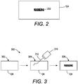
- FIG. 2 illustrates an example of the 3D printed object 124 that is marked.
- the light source 126 may be used to expose portions of the surface of the 3D printed object 124 with a marking 202.
- the marking 202 may be created by changing the color of selected portions of the surface of the 3D printed object 124 with the light source 126.
- the markings 202 may be alphanumeric text. In one embodiment, the markings 202 may be a symbol or graphic. For example, the markings 202 may be a barcode or quick response (QR) code that can be read by a scanner.
- the markings 202 on the 3D printed object 124 may provide identification information, security information, product information, and the like, associated with the 3D printed object 124.
- FIG. 3 illustrates an example process flow diagram 300 of marking the 3D printed object 124 that is printed with the particles 122 with marking additives of the present disclosure.
- a 3D printed object 124 may be provided.
- a light source 310 may emit light 312 onto the surface of the 3D printed object 124.
- the light source 310 and the light source 126 may be the same.
- the light source 310 may be a laser light source that provides a pulsed laser light source or a continuous laser light source.
- the light 312 may be emitted at wavelengths that cause the exposed portions of the particles 122 with marking additives to react and change color.
- the light 312 may be emitted from a YAG laser operating at a wavelength of approximately 1060 nm to 1070 nm.
- the light source 310 may be moved until the marking 302 is completed.
- the light source 310 may be moved in accordance with the marking instructions 108 or the 3D printed object 124 may be moved below the light source 310 in accordance with the marking instructions 108.
- the particles 122 with marking additives may be marked efficiently with the light source 310.
- the marking 202 may be written at speeds of up to 8 meters per second (8 m/s).
- light source 210 may be able to "write" over 1,000 alphanumeric characters per second.
- the particles 122 with marking additives allows the 3D printed object 124 to be marked efficiently or more quickly than other currently used marking methods (e.g., etching, additional 3D printing, and the like).
- the particles 122 with marking additives allow finer precision when writing the marking 202. This may allow the marking 202 to be written in much smaller sized fonts than currently used methods. For example, when etching, the materials may melt and the characters may be difficult to read when written too small. Alternatively, the printer may not be able to print markings that are too small (e.g., the marking may be smaller than a voxel printing size of the printer). Thus, the particles 122 with marking additives provide more flexibility in the size and location of where the marking 202 can be printed.
- FIG. 4 illustrates a flow chart of an example method 400 for producing a particle with a marking additive for a 3D printer (e.g., a selective laser sintering (SLS)-based printer) of the present disclosure.
- the method 400 may be performed by tools or a reactor, as described by the examples above, under the control of a processor.
- the method 400 begins.
- the method 400 provides a polymer resin that is compatible with the 3D printer.
- the polymer resin may be any type of polymer resin that is compatible with the SLS-based printer.
- the polymer resin may have a melting temperature and a viscosity that allows the SLS-based printer to control how the polymer resin is deposited.
- polymer resins examples include acrylic resins; polymers or copolymers produced from the monomers selected fromthe group consisting of acrylonitrile, butadiene, styrene, an acrylate, a methacrylate, and a mixture thereof; polyolefins; polyesters; polycarbonates; polylactic acid; thermoplastic polyurethanes; polyamides; polyimides; polysulfone; poly(aryl ethers); poly(aryl ether ketones); poly(aryl ether sulfones); poly(ether imide); polyarylenesulfides, poly(vinyl alcohol), polyvinylidene fluoride, or any combinations thereof.
- polymer resins are polymethyl methacrylate (PMMA), acrylonitrile butadiene styrene (ABS) resin, Nylon-6, nylon-12, polyethylene terephthalate (PET), polybutylene terephthalate (PBT), polyethylene, polypropylene, polypropylene, polyaryletherketones (PAEK), polylactic acid (PLA), thermoplastic polyurethanes (TPU), and the like, or any combinations thereof.
- PMMA polymethyl methacrylate
- ABS acrylonitrile butadiene styrene
- Nylon-6 Nylon-6
- PET polyethylene terephthalate
- PBT polybutylene terephthalate
- PAEK polyethylene
- PDA polylactic acid
- TPU thermoplastic polyurethanes
- the method 400 mixes the polymer resin with the marking additive in an amount of approximately 0.01 to 25.00 weight percent (wt%) to form the particle with the marking additive.
- the marking additive may be a light absorbing marking additive.
- the marking additive may be an infrared light absorbing marking additive.
- the amounts of the marking additives described herein may allow the polymer resin to maintain good printability in the SLS-based printer.
- the amounts of the marking additives may allow the polymer resins to maintain the similar mechanical strengths of the 3D printed object as compared to the polymer resins without the marking additives.
- the marking additive may be an additive that changes color or reacts with light emitted at wavelengths of approximately 780 nanometers (nm) to 11,000 nm.
- the wavelengths may be narrower so that the wavelengths do not overlap with the wavelengths emitted by an energy source of the SLS-based printer.
- the wavelengths of light used for marking may be approximately 1060 nm - 1070 nm.
- the light may be emitted by a semi-conducting laser beam that is continuously emitted or pulsed.
- suitable marking additives may include a metal oxide, a non-stoichiometric metal oxide, a metal hydroxide, a copper hydroxyphosphate, a copper pyrophosphate, a base copper carbonate, ammonium octamolebdate, a silver halide, a phthalocyanine, a naphthalocyanine, graphitic oxide, graphene oxide, carbon black, or a mixture thereof
- the mixture may be further processed to form a powder with particles having an average particle size of approximately 5 ⁇ m to about 200 ⁇ m, about 30 ⁇ m to about 70 ⁇ m, about 60 ⁇ m to about 110 ⁇ m, or about 100 ⁇ m to about 200 ⁇ m.
- the mixture may be melted, stirred, and dried in a fume hood (e.g., Example 1 above).
- the mixture may be mechanically stirred at a shear rate sufficient to create an adhesion of the marking additive to the particles of the polymer resin.
- the method 400 ends.
- FIG. 5 illustrates a flow chart of an example method 500 for marking a three-dimensional (3D) printed object that is printed with particles containing a marking additive.
- the method 500 may be performed by the SLS-based printer 100 or the processor 102 described above.
- the method 500 begins.
- the method 500 receives instructions to print the 3D printed object.
- the design of the 3D printed object may be created on a computing device (e.g., a computer aided drawing (CAD) program executed on the computing device).
- the design may include parameters for an amount of the particles to be dispensed on each layer along an X-Y coordinate system.
- the design may be stored as print instructions that are provided to the SLS-based printer and stored in memory in the SLS-based printer.
- the method 500 controls a powder-based 3D printer (e.g., a selective laser sintering (SLS)-based printer) to print the 3D printed object in accordance with the instructions, wherein the 3D printed object is printed with the particles containing the marking additive, wherein the particles containing the marking additive comprise a polymer resin and 0.01 to 25.00 weight percent (wt%) of the marking additive.
- the particles may include a polymer resin mixed with the marking additive.
- the polymer resin may be any type of polymer resin that is compatible with the powder-based 3D printer.
- the polymer resin may have a melting temperature and a viscosity that allows the SLS-based printer to control how the polymer resin is dispensed.
- polymer resins examples include acrylic resins; polymers or copolymers produced from the monomers selected fromthe group consisting of acrylonitrile, butadiene, styrene, an acrylate, a methacrylate, and a mixture thereof; polyolefins; polyesters; polycarbonates; polylactic acid; thermoplastic polyurethanes; polyamides; polyimides; polysulfone; poly(aryl ethers); poly(aryl ether ketones); poly(aryl ether sulfones); poly(ether imide); polyarylenesulfides, poly(vinyl alcohol), polyvinylidene fluoride, or any combinations thereof.
- polymer resins are polymethyl methacrylate (PMMA), acrylonitrile butadiene styrene (ABS) resin, Nylon-6, nylon-12, polyethylene terephthalate (PET), polybutylene terephthalate (PBT), polyethylene, polypropylene, polypropylene, polyaryletherketones (PAEK), polylactic acid (PLA), thermoplastic polyurethanes (TPU), and the like, or any combinations thereof.
- PMMA polymethyl methacrylate
- ABS acrylonitrile butadiene styrene
- Nylon-6 Nylon-6
- PET polyethylene terephthalate
- PBT polybutylene terephthalate
- PAEK polyethylene
- PDA polylactic acid
- TPU thermoplastic polyurethanes
- the marking additive may be a light absorbing marking additive. In one embodiment, the marking additive may be an infrared light absorbing marking additive.
- the amounts of the marking additives described herein may allow the polymer resin to maintain good printability in the SLS-based printer.
- the amounts of the marking additives may allow the polymer resins to maintain similar mechanical strengths of the 3D printed object as compared to the polymer resins without the marking additives.
- the marking additive may be an additive that changes color or reacts with light emitted at wavelengths of approximately 780 nanometers (nm) to 11,000 nm.
- the light may be emitted by a laser beam that is operated in a continuous mode or a pulsed mode.
- suitable marking additives may include a metal oxide, a non-stoichiometric metal oxide, a metal hydroxide, a copper hydroxyphosphate, a copper pyrophosphate, a base copper carbonate, ammonium octamolebdate, a silver halide, a phthalocyanine, a naphthalocyanine, graphitic oxide, graphene oxide, carbon black, or a mixture thereof.
- the particles may be dispensed onto a platform.
- the 3D printed object may be printed layer-by-layer by sintering selective portions of the particles, as described above.
- the method 500 receives marking instructions associated with a marking for the 3D printed object.
- the marking instructions may be provided through a user interface of the powder-based 3D printer.
- the marking instructions may be created on a separate computing device and transmitted to the powder-based 3D printer and stored in memory.
- the marking for the 3D printed object may be alphanumeric text, a graphic, an image, or any combination thereof.
- the marking may include identification information, security information, product information, and the like.
- the marking may be a bar code or a QR code that can be scanned by a reader.
- the marking may be a company logo, and so forth.
- the method 500 controls a laser to expose portions of a surface of 3D printed object in accordance with the marking instructions to change a color of the portions of the surface of 3D printed object to write the marking on the surface of the 3D printed object.
- the powder-based 3D printer may include the laser to create the marking in accordance with the marking instructions.
- the processor that controls the powder-based 3D printer may be communicatively coupled to the laser.
- the 3D printed object may be moved from the powder-based 3D printer to a marking apparatus that includes the laser.
- a laser may provide a pulsed laser light source or continuous laser light source that may be applied to the select portions of the particles.
- the light may be emitted at wavelengths of approximately 780 nm to 11,000 nm.
- the laser may be moved, the 3D printed object may be moved, or both the laser and the 3D printed object may be moved to "write" the marking onto the surface of the 3D printed object.
- the marking may be formed by a reaction of the marking additive in the particles to the light emitted by the laser. The reaction may cause the marking additive to change color in the particles.
- the method 500 ends.
Landscapes
- Chemical & Material Sciences (AREA)
- Engineering & Computer Science (AREA)
- Materials Engineering (AREA)
- Manufacturing & Machinery (AREA)
- Chemical Kinetics & Catalysis (AREA)
- Polymers & Plastics (AREA)
- Optics & Photonics (AREA)
- Organic Chemistry (AREA)
- Medicinal Chemistry (AREA)
- Physics & Mathematics (AREA)
- Health & Medical Sciences (AREA)
- Mechanical Engineering (AREA)
- Structural Engineering (AREA)
- Composite Materials (AREA)
- Civil Engineering (AREA)
- Ceramic Engineering (AREA)
- Thermal Transfer Or Thermal Recording In General (AREA)
- Compositions Of Macromolecular Compounds (AREA)
Abstract
Description
- The present disclosure relates generally to particles for selective laser sintering (SLS)-based additive manufacturing systems and, more particularly, to particles that include marking additives for SLS-based additive manufacturing systems.
- Three-dimensional (3D) printing is a technology that allows 3D objects to be printed with controlled internal and external geometry layer-by-layer using a computer-aided design (CAD) file. For example, a starting material may be used and selectively melted and bonded to form a 3D object. Different types of 3D printers are available today. The different types of 3D printers may perform different types of additive printing. Examples of 3D printing technology may include extrusion-based printing, such as fused filament fabrication (FFF), also known as fused deposition modeling (FDM), selective laser sintering (SLS), selective laser melting (SLM), electronic beam melting (EBM), digital light processing (DLP), stereolithography (SLA), laminated object manufacturing (LOM), binder jetting, and the like.
- According to aspects illustrated herein, there are provided a particle for use in three-dimensional (3D) printers. One disclosed feature of the embodiments is a particle, comprising a polymer resin that is compatible with a 3D printing process to print a 3D object and a marking additive that allows selective portions of the 3D object to change color when exposed to a light, wherein the marking additive is added to approximately 0.01 to 25.00 weight percent (wt%).
- Another disclose feature of the embodiments is a method to produce a particle with a marking additive for a 3D printer. The method comprises providing a polymer resin that is compatible with the 3D printer and mixing the polymer resin with the marking additive in amount of approximately 0.01 to 25.00 weight percent (wt%) to form the particle with the marking additive.
- Another disclosed feature of the embodiments is a method marking a three-dimensional (3D) printed object that is printed with a particles with a marking additive. The method comprises receiving, by a processor, instructions to print the 3D printed object, controlling, by the processor, a powder-based 3D printer to print the 3D printed object in accordance with the instructions, wherein the 3D printed object is printed with the particles containing the marking additive, wherein the particles containing the marking additive comprises a polymer resin and 0.01 to 25.00 weight percent (wt) of the marking additive, receiving, by the processor, marking instructions associated with a marking for the 3D printed object, and controlling, by the processor, a laser to expose portions of a surface of 3D printed object in accordance with the marking instructions to change a color of the portions of the surface of 3D printed object to write the marking on the surface of the 3D printed object.
- The teaching of the present disclosure can be readily understood by considering the following detailed description in conjunction with the accompanying drawings, in which:
-
FIG. 1 illustrates an example of a selective laser sintering (SLS)-based printer that uses the particles with the marking additives of the present disclosure; -
FIG. 2 illustrates an object that is printed with the particles containing the marking additives of the present disclosure that is marked; -
FIG. 3 illustrates an example process flow diagram of marking the 3D printed object printed with the particles containing the marking additives of the present disclosure; -
FIG. 4 illustrates a flow chart of an example method for producing a particle with a marking additive for an SLS-based printer; and -
FIG. 5 illustrates a flow chart of an example method for marking a 3D printed object that is printed with the particles containing the marking additives. - To facilitate understanding, identical reference numerals have been used, where possible, to designate identical elements that are common to the figures.
- The present disclosure is related to a particle with marking additives and a method for making the same. In addition, the particle with marking additives can be used to print 3D objects and mark the 3D objects by changing the color of selected portions of the surface of the 3D object. As discussed above, various 3D printing technologies are used today. Additive manufacturing methods using powdered materials may include powder bed fusion (PBF), selective laser sintering (SLS), selective heat sintering (SHM), binder jetting, and multi jet fusion (MJF). In the SLS printing method, for instance, the particles are fused together by the energy from a laser. However, after the 3D object is printed, marking images can be added to provide identification of the object, labeling information, security information, and the like.
- Currently available ways of marking a 3D printed object have many drawbacks. For example, a separately printed label can be applied to the object. However, the label can be easily removed or damaged. Another example may be to physically print the label into the object as part of the printing process. In other words, the desired marks can be physically printed (e.g., the desired letters are raised portions on the surface of the 3D object) into the 3D printed object. Another example may be to etch away or melt away portions of the 3D printed object using, for example, laser engraving. However, since most 3D-printed objects have a rough surface texture, these solutions may not be suitable to achieve high contrast markings for many areas of application. Further, these solutions may suffer from additional complexity, limitations on how small markings can be printed due to the physical properties of the material, and so forth.
- The present disclosure provides a particle with marking additives that can be used in SLS-based 3D printers. The marking additives can absorb light to change the optical properties of the particles. For example, certain marking additives can result in optical or color change of portions of the 3D printed object fabricated with the particles with marking additives when exposed to infrared light.
- Thus, markings can be written directly into the surface of the 3D printed object by exposing desired locations on the surface to a light source. The portions that are exposed to the light source may change color and the marking may be written on the surface of the 3D printed object. The markings may be written to any desired size. In addition, the markings may be added relatively quickly as the marking additive may change color when exposed to light at speeds up to 8 meters per second. Thus, the markings created by the particles with the marking additives may be more permanent and secure than currently available marking methods.
-
FIG. 1 illustrates an example of a selective laser sintering (SLS)-basedprinter 100 that uses particles with marking additives 122 (also herein referred to as aparticle 122 or particles 122) of the present disclosure. AlthoughFIG. 1 illustrates a particular type of SLS-based printer as an example, it should be noted that theparticles 122 can be used with any type of powder-based printer or additive printing process. In one embodiment, the SLS-basedprinter 100 may include ahopper 120 that is filled with theparticles 122. Thehopper 120 may be located adjacent to amovable platform 112. Theplatform 112 may move up and down as each layer of theparticles 122 is printed. - In one embodiment, the
hopper 120 may have a movable bottom that can push theparticles 122 above an edge of the hopper. Aroller 116 may move laterally (as shown by an arrow 118) to dispense theparticles 122 on to theplatform 112. Theroller 116 may provide a smooth even layer of theparticles 122 for each layer of a three-dimensional (3D) printedobject 124 that is printed. It should be noted thatFIG. 1 illustrates one example of how theparticles 122 may be dispensed. Other examples may also be within the scope of the present disclosure. - In one embodiment, an energy source 110 (e.g., a laser, an ultra violet (UV) light source, a heat source, and the like) may be located above the
platform 112. Theenergy source 110 may selectively sinter or fuse theparticles 122 to print the 3D printedobject 124. For example, theenergy source 110 may fuse theparticles 122 layer-by-layer until the entire 3D printedobject 124 is printed. In one embodiment, theenergy source 110 may operate at specific settings (e.g., power, frequency, a wavelength, and the like) that do not cause the marking additive in theparticles 122 to change color. In other words, theenergy source 110 may operate at the settings that allow sintering or fusing of theparticles 122 to print a 3D object, but do not overlap with the wavelength of light emitted by alight source 126, described below. - In one embodiment, the
energy source 110 may be coupled to a gimbal or movable arm that allows theenergy source 110 to move along a two-dimensional plane parallel to a layer of theparticles 122 on theplatform 112. In another embodiment, theenergy source 110 may be stationary and theplatform 112 may also move side-to-side below theenergy source 110. - In one embodiment, a sintering fluid may be dispensed onto the layer of
particles 122. The sintering fluid may be dispensed in accordance with a desired shape or pattern of a particular layer of the 3D printedobject 124. Theenergy source 110 may be applied to the layer and the portions of the layer ofparticles 122 that receive the sintering fluid may be fused together to form a layer of the 3D printedobject 124. - In one embodiment, the SLS-based printer may be controlled by a
processor 102 that is communicatively coupled to theenergy source 110, theplatform 112, and theroller 116. The SLS-basedprinter 100 may also include amemory 104 that is communicatively coupled to theprocessor 102. Thememory 104 may be any type of non-transitory computer readable medium. For example, thememory 104 may be a hard disk drive, a solid state drive, a random access memory, a read-only memory, and the like. - In one embodiment, the
memory 104 may include instructions that are executed by theprocessor 102. For example, thememory 104 may includeprint instructions 106 and markinginstructions 108. In one embodiment, theprocessor 102 may control the feed of theparticles 122, movement of theenergy source 110, and theplatform 112 in accordance with theprint instructions 106 to print the 3D printedobject 124. - In one embodiment, the
processor 102 may also control thelight source 126 to mark the 3D printedobject 124. Although thelight source 126 is illustrated inFIG. 1 as being part of the SLS-basedprinter 100, it should be noted that thelight source 126 may be part of a separate device controlled by a separate controller or processor. In other words, after the 3D printedobject 124 is completed, the object can be transferred to another apparatus with thelight source 126 to receive light for marking the 3D printedobject 124. - The
processor 102 may mark the 3D printedobject 124 in accordance with the markinginstructions 108. Thelight source 126 may be a laser that may be operated at a wavelength in an infrared region ranging from approximately 700 nanometers (nm) to 10.6 microns (µm). Examples of lasers may include solid-state lasers, diode or diode array lasers, yttrium aluminum garnet (YAG) lasers, fiber lasers, carbon dioxide (CO2) lasers, and the like. Thelight source 126 may be operated in a pulsed mode or a continuous mode. - As noted above, the
particles 122 may include a marking additive. When theparticles 122 with marking additives are exposed to a certain wavelength of light from thelight source 126, the surface of the 3D printedobject 124 that is exposed to the light may change color. Thus, the marking can be directly "written" on the 3D printedobject 124 by thelight source 126. Notably, the marking is not being etched or physically formed by additional printing of theparticles 122. Rather, the optical properties of theparticles 122 with marking additives are being changed to create the markings. As a result, the markings may be more secure and permanent than what is produced using current methods to add markings to 3D printed objects. - In one embodiment, the
particles 122 may be formulated or created by mixing a polymer resin with a marking additive. The polymer resin may be any type of polymer resin that is compatible with the SLS-basedprinter 100. For example, the polymer resin may have a melting temperature and a viscosity that allows the SLS-basedprinter 100 to control how the polymer resin is deposited. The polymer resin may be a thermoplastic, including crystalline, semi-crystalline, or amorphous polymer resins. Examples of polymer resins that can be used include acrylic resins; polymers or copolymers produced from the monomers selected from the group consisting of acrylonitrile, butadiene, styrene, an acrylate, a methacrylate, and a mixture thereof; polyolefins; polyesters; polycarbonates; polylactic acid; thermoplastic polyurethanes; polyamides; polyimides; polysulfone; poly(aryl ethers); poly(aryl ether ketones); poly(aryl ether sulfones); poly(ether imide); polyarylenesulfides, poly(vinyl alcohol), polyvinylidene fluoride, or any combinations thereof. Specific examples of the polymer resins are polymethyl methacrylate (PMMA), acrylonitrile butadiene styrene (ABS) resin, Nylon-6, nylon-12, polyethylene terephthalate (PET), polybutylene terephthalate (PBT), polyethylene, polypropylene, polypropylene, polyaryletherketones (PAEK), polylactic acid (PLA), thermoplastic polyurethanes (TPU), and the like, or any combinations thereof. - In one embodiment, the marking additives used in the
particles 122 of the present disclosure should possess good light fastness and weatherability. In addition, the marking additives should be compatible with the manufacturing processes of theparticles 122 and the 3D printing processes described herein. For example, the marking additives may have good thermal stability at a temperature that is at least that of a melting point or softening temperature of theparticles 122. Furthermore, the marking additive may be compatible with the polymer resins used for theparticles 122, be environmentally friendly, readily available, and non-toxic. - In one embodiment, the marking additive may be a light absorbing marking additive. In one embodiment, the marking additive may be an infrared light absorbing marking additive. The marking additive may possess efficient absorption of the light radiation within a wavelength region of the
light source 126. The marking additive may be added or mixed with the polymer resin at approximately 0.01 weight percent (wt%) to 25.00 wt%. In one embodiment, the marking additive may be added at approximately 0.50 wt% to 10.00 wt%. In one embodiment, the marking additive may be added at approximately 0.50 wt% to 5.00 wt%. The weight percentage may be a ratio of the marking additive to a total weight of theparticle 122. - In one embodiment, the amounts of the marking additives described herein may allow the polymer resin to maintain good printability in the SLS-based
printer 100. In addition, the amounts of the marking additives may allow the polymer resins to maintain similar mechanical strengths of the 3D printedobject 124 as compared to the polymer resins without the marking additives. - In one embodiment, the marking additive may be an additive that changes color or reacts when exposed to a light emitted by the
light source 126. In one embodiment, the marking additive may include an infrared absorption component that absorbs wavelengths of approximately 700 nanometers (nm) to 11,000 nm. For example, the light may be emitted by a laser beam that is operated at a continuous mode or a pulsed mode. In one embodiment, the marking additive may absorb wavelengths of approximately 780 nm to about 2500 nm. For example, the light may be emitted by a solid-state laser, including yttrium orthovanadate (Nd:YVO4), yttrium lithium fluoride (Nd:YLF) and yttrium aluminium garnet (Nd:YAG), which operates in the infrared spectrum at around 1064 nm. In one embodiment, examples of the infrared absorption component may include a metal oxide, a non-stoichiometric metal oxide, a metal hydroxide, a copper hydroxyphosphate, a copper pyrophosphate, a base copper carbonate, ammonium octamolebdate, a silver halide, a phthalocyanine, a naphthalocyanine, graphitic oxide, graphene oxide, carbon black, or a mixture thereof. - Examples of metals for the metal oxide or the non-stoichiometric metal oxide may include tin, antimony, bismuth, boron, titanium, indium, iron, copper, molybdenum, tungsten, vanadium, or any combination thereof. Examples of the metal oxide or non-stoichiometric metal oxide may include titanium oxide, boron anhydride, tin oxide, bismuth oxide, copper oxide, iron oxide, molybdenum oxide, vanadium oxide, antimony-doped tin oxide, antimony-doped indium tin oxide, reduced indium tin oxide, oxygen-deficient bismuth oxide, metal hydroxides, or any combination thereof. Examples of the metal hydroxide may include aluminum hydroxide, magnesium hydroxide, copper hydroxide, and a mixture thereof. Examples of the phthalocyanines include metal-free phthaocyanines and metal phthalocyanines such as copper phthocyanines. Similarly, the example of the naphthalocyanines may include metal-free or metal naphthalocyanines.
- In one embodiment, the
particles 122 may include a marking additive that absorbs light at wavelengths of approximately 780 nm to 2500 nm emitted by a near infrared laser. For example, the near infrared laser may be a YAG laser which operates at a wavelength of approximately 1064 nm. In one embodiment, theparticles 122 may include a marking additive that absorbs light at wavelengths above 2500 nm using a CO2 laser operating at approximately 10.6 µm. - In one embodiment, the marking additive used for the
particles 122 disclosed herein may further comprise a developer component. The developer component itself may not be sensitive to the radiation emitted by thelight source 126. However, when used in combination with marking additives described above (e.g., the metal oxides, metal salts, and/or the metal compounds, carbon black, graphene oxide, or any combination thereof), the developer component may be reactive to assist color change of the portions of the 3D printed objected 124 printed with theparticles 122. Suitable developer components may include a polyphenol, a melamine resin, a polysaccharide, or any combination thereof. - In one embodiment, the marking additive may be provided in a particulate form. The marking additive may be particles having an average diameter of approximately 10 nm to 5000 nm. In one embodiment, the particles may have an average diameter of approximately 10 nm to 1000 nm.
- In one embodiment, the marking additive may also include an inert support material. Examples of the inert support material may include silica, alumina, titanium oxide, zinc oxide, mica, calcium carbonate, kaolin, talc, ceramic, and the like.
- In one embodiment, the
particles 122 may also include a pigment or a colorant. The pigment or colorant may be inert to the radiation received during the marking process. However, the pigment or colorant may provide a background to enhance the marking contrast or visibility. Examples of the pigment or colorant that can be used include titanium oxide, zinc oxide, iron oxide, carbon black, organic pigments, and the like. - In one embodiment, the
particles 122 may be formed from a mixture of the polymer resin and the marking additive. Theparticles 122 may have an average particle size of about 5 µm to about 200 µm, about 30 µm to about 70 µm, about 60 µm to about 110 µm, or about 100 µm to about 200 µm. For instance, theparticles 122 may be obtained by cryogenic grinding or precipitation processes using a blend of the polymer and the marking additive. - In one embodiment, the
particles 122 are produced according to a melt emulsification process. In one embodiment, the process may include mixing a mixture comprising a blend of the polymer and the marking additive, and a carrier fluid that is immiscible with the polymer blend. In one embodiment, inorganic oxide nanoparticles can be optionally added. The mixture may be heated to a temperature greater than a melting point or a softening temperature of the polymer resin. Shear may be applied to the mixture at a shear rate that is sufficiently high to disperse the polymer resin in the carrier fluid. The mixture may then be cooled to below the melting point or softening temperature of the polymer resin to form solidified particles, or particulates, comprising the polymer and the marking additive. The particulates can then be separated from the carrier fluid. - In the process described herein the inorganic oxide nanoparticles may be optionally added as a surface active agent and/or a stabilizer component to produce the
particle 122 with better controlled particle size and particle size distribution. Furthermore, the inorganic oxide nanoparticles associated with the outer surface of theresultant particles 122 may serve as a flow aid to improve the followability of the 3D printing powder. - Suitable carrier fluids for the melt emulsification process may have a viscosity at 25°C of about 1,000 centistokes (cSt) to about 150,000 cSt (or about 1,000 cSt to about 60,000 cSt, or about 40,000 cSt to about 100,000 cSt, or about 75,000 cSt to about 150,000 cSt). Examples of the carrier fluids may include, but are not limited to, silicone oil, polysiloxanes modified with fatty acids, polysiloxanes modified with fatty alcohols, polysiloxanes modified with polyoxy alkylenes, and the like, fluorinated silicone oils, polyethylene glycols, paraffins, and any combination thereof. Examples of silicone oils include, but are not limited to, polydimethylsiloxane, methylphenylpolysiloxane, an alkyl modified polydimethylsiloxane, an alkyl modified methylphenylpolysiloxane, an amino modified polydimethylsiloxane, an amino modified methylphenylpolysiloxane, a fluorine modified polydimethylsiloxane, a fluorine modified methylphenylpolysiloxane, a polyether modified polydimethylsiloxane, a polyether modified methylphenylpolysiloxane, and the like, and any combination thereof. The carrier fluid may be present in the mixture at about 40 wt% to about 90 wt% (or about 75 wt% to about 95 wt%, or about 70 wt% to about 90 wt%, or about 55 wt% to about 80 wt%, or about 50 wt% to about 75 wt%, or about 40 wt% to about 60 wt%) of the polymer and carrier fluid combined.
- The inorganic oxide nanoparticles suitable for the melt emulsification process may include, but are not limited to, silica, titania, zirconia, alumina, iron oxide, copper oxide, tin oxide, and the like, and any combination thereof. The oxide nanoparticles may by hydrophilic or hydrophobic, which may be native to the particle or a result of surface treatment of the particle. Illustrative examples of the oxide nanoparticles include a silica nano particle having a hydrophobic surface treatment, like dimethyl silyl, trimethyl silyl, and the like. Commercially available examples of silica nanoparticles include, but are not limited to, AEROSIL® particles available from Evonik, such as AEROSIL® R812S, AEROSIL® RX50, AEROSIL® 380, and the like. The oxide nanoparticles may have an average diameter of about 1 nm to about 500 nm (or about 10 nm to about 150 nm, or about 25 nm to about 100 nm, or about 100 nm to about 250 nm, or about 250 nm to about 500 nm). Oxide nanoparticles may be included in the mixture at a concentration of about 0.01 wt% to about 10 wt% (or about 0.01 wt% to about 1 wt%, or about 0.1 wt% to about 3 wt%, or about 1 wt% to about 5 wt%, or about 5 wt% to about 10 wt%) based on the weight of the polymer.
- The melt emulsification process may be carried out, for example, using extruders (e.g., continuous extruders, batch extruders), reactors with mixing or inline homogenizer systems, and the like, and apparatuses derived therefrom.
- In a batch-based process, 400 grams (g) of polydimethylsiloxane oil (10,000 cSt viscosity measured at room temperature), 120 g of polyamide (PA12) pellets containing 2.5 weight percent (wt%) of antimony (Sb) doped tin oxide, and 0.4 g of R812S silica were added into a 1 liter glass kettle reactor. The mixture was heated to 220 degrees Celsius (°C) for over 90 minutes with mixing at 260 rotations per minute (RPM) to form a melt dispersion. The melt dispersion was then mechanically stirred or mixed at 1250 RPM for an additional 40 minutes. After turning off the heat and stirring, the mixture slurry was discharged to room temperature, followed by washing with Heptane three times to remove the silicone oil. The resulting powder was dried in a fume hood to produce a powder with an average particle size of approximately 50 µm.
- In an extrusion-based process, 45 parts of ELASTOLLAN® 1190A10 thermoplastic polyurethane (TPU), 1.6 parts of copper hydroxyphosphase, 0.6 part of AEROSIL® RX50 silica, and 52.8 parts of polydimethylsiloxane oil (10,000 cSt viscosity measured at room temperature), are fed to the 25mm twin-screw extruder (Werner & Pfleiderer ZSK-25), which is set at a temperature from 240-260 °C, and mixing RPM from 900 - 1100. Resultant slurry is diluted with heptane and filtered to collect the particles with an average particle size from 25-75 µm.
- In one example, 100 parts PA12 particles (having an average diameter of approximately 50 µm), 2 parts of titanium dioxide pigment (particle size in the range of 100 - 500 nm), and 2 parts of Sb-doped tin oxide were placed in a mixing reactor. The resultant mixture was blended at shear level that was sufficient to enable adhesion of the metal oxide on the polymer particles.
-
FIG. 2 illustrates an example of the 3D printedobject 124 that is marked. For example, thelight source 126 may be used to expose portions of the surface of the 3D printedobject 124 with a marking 202. The marking 202 may be created by changing the color of selected portions of the surface of the 3D printedobject 124 with thelight source 126. - In one embodiment, the
markings 202 may be alphanumeric text. In one embodiment, themarkings 202 may be a symbol or graphic. For example, themarkings 202 may be a barcode or quick response (QR) code that can be read by a scanner. Themarkings 202 on the 3D printedobject 124 may provide identification information, security information, product information, and the like, associated with the 3D printedobject 124. -
FIG. 3 illustrates an example process flow diagram 300 of marking the 3D printedobject 124 that is printed with theparticles 122 with marking additives of the present disclosure. - At
block 302, a 3D printedobject 124 may be provided. Atblock 304, alight source 310 may emit light 312 onto the surface of the 3D printedobject 124. Thelight source 310 and thelight source 126 may be the same. For example, thelight source 310 may be a laser light source that provides a pulsed laser light source or a continuous laser light source. The light 312 may be emitted at wavelengths that cause the exposed portions of theparticles 122 with marking additives to react and change color. In one embodiment, the light 312 may be emitted from a YAG laser operating at a wavelength of approximately 1060 nm to 1070 nm. - At
block 306, thelight source 310 may be moved until the marking 302 is completed. For example, thelight source 310 may be moved in accordance with the markinginstructions 108 or the 3D printedobject 124 may be moved below thelight source 310 in accordance with the markinginstructions 108. - In one embodiment, the
particles 122 with marking additives may be marked efficiently with thelight source 310. For example, the marking 202 may be written at speeds of up to 8 meters per second (8 m/s). Thus, light source 210 may be able to "write" over 1,000 alphanumeric characters per second. Thus, theparticles 122 with marking additives allows the 3D printedobject 124 to be marked efficiently or more quickly than other currently used marking methods (e.g., etching, additional 3D printing, and the like). - In addition, the
particles 122 with marking additives allow finer precision when writing the marking 202. This may allow the marking 202 to be written in much smaller sized fonts than currently used methods. For example, when etching, the materials may melt and the characters may be difficult to read when written too small. Alternatively, the printer may not be able to print markings that are too small (e.g., the marking may be smaller than a voxel printing size of the printer). Thus, theparticles 122 with marking additives provide more flexibility in the size and location of where the marking 202 can be printed. -
FIG. 4 illustrates a flow chart of anexample method 400 for producing a particle with a marking additive for a 3D printer (e.g., a selective laser sintering (SLS)-based printer) of the present disclosure. Themethod 400 may be performed by tools or a reactor, as described by the examples above, under the control of a processor. - At
block 402, themethod 400 begins. Atblock 404, themethod 400 provides a polymer resin that is compatible with the 3D printer. The polymer resin may be any type of polymer resin that is compatible with the SLS-based printer. For example, the polymer resin may have a melting temperature and a viscosity that allows the SLS-based printer to control how the polymer resin is deposited. Examples of polymer resins that can be used include acrylic resins; polymers or copolymers produced from the monomers selected fromthe group consisting of acrylonitrile, butadiene, styrene, an acrylate, a methacrylate, and a mixture thereof; polyolefins; polyesters; polycarbonates; polylactic acid; thermoplastic polyurethanes; polyamides; polyimides; polysulfone; poly(aryl ethers); poly(aryl ether ketones); poly(aryl ether sulfones); poly(ether imide); polyarylenesulfides, poly(vinyl alcohol), polyvinylidene fluoride, or any combinations thereof. Specific examples of the polymer resins are polymethyl methacrylate (PMMA), acrylonitrile butadiene styrene (ABS) resin, Nylon-6, nylon-12, polyethylene terephthalate (PET), polybutylene terephthalate (PBT), polyethylene, polypropylene, polypropylene, polyaryletherketones (PAEK), polylactic acid (PLA), thermoplastic polyurethanes (TPU), and the like, or any combinations thereof. - At
block 406, themethod 400 mixes the polymer resin with the marking additive in an amount of approximately 0.01 to 25.00 weight percent (wt%) to form the particle with the marking additive. In one embodiment, the marking additive may be a light absorbing marking additive. In one embodiment, the marking additive may be an infrared light absorbing marking additive. - In one embodiment, the amounts of the marking additives described herein may allow the polymer resin to maintain good printability in the SLS-based printer. In addition, the amounts of the marking additives may allow the polymer resins to maintain the similar mechanical strengths of the 3D printed object as compared to the polymer resins without the marking additives.
- In one embodiment, the marking additive may be an additive that changes color or reacts with light emitted at wavelengths of approximately 780 nanometers (nm) to 11,000 nm. In one embodiment, the wavelengths may be narrower so that the wavelengths do not overlap with the wavelengths emitted by an energy source of the SLS-based printer. For example, the wavelengths of light used for marking may be approximately 1060 nm - 1070 nm.
- In one embodiment, the light may be emitted by a semi-conducting laser beam that is continuously emitted or pulsed. Examples of suitable marking additives may include a metal oxide, a non-stoichiometric metal oxide, a metal hydroxide, a copper hydroxyphosphate, a copper pyrophosphate, a base copper carbonate, ammonium octamolebdate, a silver halide, a phthalocyanine, a naphthalocyanine, graphitic oxide, graphene oxide, carbon black, or a mixture thereof
- In one embodiment, after the polymer resin and the marking additive are mixed together to form a mixture, the mixture may be further processed to form a powder with particles having an average particle size of approximately 5 µm to about 200 µm, about 30 µm to about 70 µm, about 60 µm to about 110 µm, or about 100 µm to about 200 µm. In one embodiment, the mixture may be melted, stirred, and dried in a fume hood (e.g., Example 1 above). In one embodiment, the mixture may be mechanically stirred at a shear rate sufficient to create an adhesion of the marking additive to the particles of the polymer resin. At
block 408, themethod 400 ends. -
FIG. 5 illustrates a flow chart of anexample method 500 for marking a three-dimensional (3D) printed object that is printed with particles containing a marking additive. Themethod 500 may be performed by the SLS-basedprinter 100 or theprocessor 102 described above. - At
block 502, themethod 500 begins. Atblock 504, themethod 500 receives instructions to print the 3D printed object. For example, the design of the 3D printed object may be created on a computing device (e.g., a computer aided drawing (CAD) program executed on the computing device). The design may include parameters for an amount of the particles to be dispensed on each layer along an X-Y coordinate system. The design may be stored as print instructions that are provided to the SLS-based printer and stored in memory in the SLS-based printer. - At
block 506, themethod 500 controls a powder-based 3D printer (e.g., a selective laser sintering (SLS)-based printer) to print the 3D printed object in accordance with the instructions, wherein the 3D printed object is printed with the particles containing the marking additive, wherein the particles containing the marking additive comprise a polymer resin and 0.01 to 25.00 weight percent (wt%) of the marking additive. The particles may include a polymer resin mixed with the marking additive. The polymer resin may be any type of polymer resin that is compatible with the powder-based 3D printer. For example, the polymer resin may have a melting temperature and a viscosity that allows the SLS-based printer to control how the polymer resin is dispensed. Examples of polymer resins that can be used include acrylic resins; polymers or copolymers produced from the monomers selected fromthe group consisting of acrylonitrile, butadiene, styrene, an acrylate, a methacrylate, and a mixture thereof; polyolefins; polyesters; polycarbonates; polylactic acid; thermoplastic polyurethanes; polyamides; polyimides; polysulfone; poly(aryl ethers); poly(aryl ether ketones); poly(aryl ether sulfones); poly(ether imide); polyarylenesulfides, poly(vinyl alcohol), polyvinylidene fluoride, or any combinations thereof. Specific examples of the polymer resins are polymethyl methacrylate (PMMA), acrylonitrile butadiene styrene (ABS) resin, Nylon-6, nylon-12, polyethylene terephthalate (PET), polybutylene terephthalate (PBT), polyethylene, polypropylene, polypropylene, polyaryletherketones (PAEK), polylactic acid (PLA), thermoplastic polyurethanes (TPU), and the like, or any combinations thereof. - In one embodiment, the marking additive may be a light absorbing marking additive. In one embodiment, the marking additive may be an infrared light absorbing marking additive.
- In one embodiment, the amounts of the marking additives described herein may allow the polymer resin to maintain good printability in the SLS-based printer. In addition, the amounts of the marking additives may allow the polymer resins to maintain similar mechanical strengths of the 3D printed object as compared to the polymer resins without the marking additives.
- In one embodiment, the marking additive may be an additive that changes color or reacts with light emitted at wavelengths of approximately 780 nanometers (nm) to 11,000 nm. For example, the light may be emitted by a laser beam that is operated in a continuous mode or a pulsed mode. Examples of suitable marking additives may include a metal oxide, a non-stoichiometric metal oxide, a metal hydroxide, a copper hydroxyphosphate, a copper pyrophosphate, a base copper carbonate, ammonium octamolebdate, a silver halide, a phthalocyanine, a naphthalocyanine, graphitic oxide, graphene oxide, carbon black, or a mixture thereof.
- The particles may be dispensed onto a platform. The 3D printed object may be printed layer-by-layer by sintering selective portions of the particles, as described above.
- At
block 508, themethod 500 receives marking instructions associated with a marking for the 3D printed object. In one embodiment, the marking instructions may be provided through a user interface of the powder-based 3D printer. In one embodiment, the marking instructions may be created on a separate computing device and transmitted to the powder-based 3D printer and stored in memory. - The marking for the 3D printed object may be alphanumeric text, a graphic, an image, or any combination thereof. The marking may include identification information, security information, product information, and the like. The marking may be a bar code or a QR code that can be scanned by a reader. The marking may be a company logo, and so forth.
- At
block 510, themethod 500 controls a laser to expose portions of a surface of 3D printed object in accordance with the marking instructions to change a color of the portions of the surface of 3D printed object to write the marking on the surface of the 3D printed object. In one embodiment, the powder-based 3D printer may include the laser to create the marking in accordance with the marking instructions. In one embodiment, the processor that controls the powder-based 3D printer may be communicatively coupled to the laser. In one embodiment, the 3D printed object may be moved from the powder-based 3D printer to a marking apparatus that includes the laser. - In one embodiment, a laser may provide a pulsed laser light source or continuous laser light source that may be applied to the select portions of the particles. The light may be emitted at wavelengths of approximately 780 nm to 11,000 nm. The laser may be moved, the 3D printed object may be moved, or both the laser and the 3D printed object may be moved to "write" the marking onto the surface of the 3D printed object. The marking may be formed by a reaction of the marking additive in the particles to the light emitted by the laser. The reaction may cause the marking additive to change color in the particles. At
block 512, themethod 500 ends. - It will be appreciated that variants of the above-disclosed and other features and functions, or alternatives thereof, may be combined into many other different systems or applications. Various presently unforeseen or unanticipated alternatives, modifications, variations, or improvements therein may be subsequently made by those skilled in the art which are also intended to be encompassed by the following claims.
Claims (20)
- A particle for 3D printing manufacturing systems, comprising:a polymer resin that is compatible with a 3D printing process to print a three-dimensional (3D) object; anda marking additive that allows selective portions of the 3D object to change color when exposed to a light, wherein the marking additive is added to approximately 0.01 to 25.00 weight percent (wt%).
- The particle of claim 1, wherein the polymer resin comprises at least one of: acrylic resins; polymers or copolymers produced from the monomers selected fromthe group consisting of acrylonitrile, butadiene, styrene, an acrylate, a methacrylate, and the mixture thereof; polyolefins; polyesters; polycarbonates; polylactic acid; thermoplastic polyurethanes; polyamides; polyimides; polysulfone; poly(aryl ethers); poly(aryl ether ketones); poly(aryl ether sulfones); poly(ether imide); polyarylenesulfides, poly(vinyl alcohol), or polyvinylidene fluoride.
- The particle of claim 1, wherein the marking additive comprises an infrared absorption component that absorbs the light at wavelengths of approximately 780 nanometers (nm) to 11000 nm.
- The particle of claim 1, wherein the marking additive comprises at least one of: a metal oxide, a non-stoichiometric metal oxide, a metal hydroxide, a copper hydroxyphosphate, a copper pyrophosphate, a base copper carbonate, ammonium octamolebdate, a silver halide, a phthalocyanine, a naphthalocyanine, graphitic oxide, graphene oxide, or carbon black.
- The particle of claim 4, wherein the metal oxide or the non-stoichiometric metal oxide comprise at least one of: tin, antimony, bismuth, boron, titanium, indium, iron, copper, molybdenum, tungsten, vanadium.
- The particle of claim 4, wherein the metal hydroxide comprises at least one of: aluminum hydroxide, magnesium hydroxide, or copper hydroxide.
- The particle of claim 1, further comprising:
a developer component comprising at least one of: a polyphenol, a melamine resin, or polysaccharide. - The particle of claim 1, further comprising:
a support material comprising at least one of: silica, alumina, titanium oxide, mica, kaolin, zinc oxide, calcium carbonate, talc, or ceramic. - The particle of claim 1, further comprising:
a pigment or a colorant. - The particle of claim 1, further comprising a plurality of nanoparticles dispersed on the surface of the particle at approximately 0.05 to 5 weight percent (wt%).
- The particle of claim 10, wherein the nanoparticles comprise inorganic oxide with an average diameter of about 1 nanometers (nm) to about 500 nm comprising at least one of: silica, titania, zirconia, alumina, iron oxide, copper oxide, or tin oxide.
- A method for producing a particle with a marking additive for a 3D printer, comprising:providing a polymer resin that is compatible with the 3D printer; andmixing the polymer resin with the marking additive in amount of approximately 0.01 to 25.00 weight percent (wt%) to form the particle with the marking additive.
- The method of claim 12, wherein the polymer resin comprises at least one of: acrylic resins; polymers or copolymers produced from the monomers selected fromthe group consisting of acrylonitrile, butadiene, styrene, an acrylate, a methacrylate, and the mixture thereof; polyolefins; polyesters; polycarbonates; polylactic acid; thermoplastic polyurethanes; polyamides; polyimides; polysulfone; poly(aryl ethers); poly(aryl ether ketones); poly(aryl ether sulfones); poly(ether imide); polyarylenesulfides, or poly(vinyl alcohol), polyvinylidene fluoride.
- The method of claim 12, wherein the marking additive comprises at least one of: a metal oxide, a non-stoichiometric metal oxide, a metal hydroxide, a copper hydroxyphosphate, a copper pyrophosphate, a base copper carbonate, ammonium octamolebdate, a silver halide, a phthalocyanine, a naphthalocyanine, graphitic oxide, graphene oxide, or carbon black.
- The method of claim 11, wherein the mixing comprises:heating a mixture of the polymer resin and the marking additive in a carrier fluid to a temperature at or above a melting point of the polymer, wherein the polymer and the carrier fluid are substantially immiscible at the temperature;applying shear to the mixture to disperse the polymer as liquefied droplets in the marking additive at the temperature;cooling the carrier fluid to a second temperature at to form particulates of the polymer resin and the marking additive particulates; andseparating the particulates from the carrier fluid.
- The method of claim 15, wherein the mixture further comprises inorganic oxide nanoparticles at approximately 0.05 to 5 weight percent (wt%) comprising at least one of: silica, titania, zirconia, alumina, iron oxide, copper oxide, or tin oxide.
- A method for marking a three-dimensional (3D) printed object that is printed with particles containing a marking additive, comprising:receiving, by a processor, instructions to print the 3D printed object;controlling, by the processor, a powder-based 3D printer to print the 3D printed object in accordance with the instructions, wherein the 3D printed object is printed with the particles containing the marking additive, wherein the particles containing the marking additive comprises a polymer resin and 0.01 to 25.00 weight percent (wt%) of the marking additive;receiving, by the processor, marking instructions associated with a marking for the 3D printed object; andcontrolling, by the processor, a laser to expose portions of a surface of 3D printed object in accordance with the marking instructions to change a color of the portions of the surface of 3D printed object to write the marking on the surface of the 3D printed object.
- The method of claim 17, wherein the laser comprises at least one of a fiber laser, a diode laser, a diode array laser, a yttrium aluminum garnet (YAG) laser, or a carbon dioxide laser that emits light at approximately 780 nanometers (nm) to 11,000 nm.
- The method of claim 17, wherein the polymer resin comprises at least one of: acrylic resins; polymers or copolymers produced from the monomers selected fromthe group consisting of acrylonitrile, butadiene, styrene, an acrylate, a methacrylate, and the mixture thereof; polyolefins; polyesters; polycarbonates; polylactic acid; thermoplastic polyurethanes; polyamides; polyimides; polysulfone; poly(aryl ethers); poly(aryl ether ketones); poly(aryl ether sulfones); poly(ether imide); polyarylenesulfides, or poly(vinyl alcohol), polyvinylidene fluoride.
- The method of claim 17, wherein the marking additive comprises at least one of: a metal oxide, a non-stoichiometric metal oxide, a metal hydroxide, a copper hydroxyphosphate, a copper pyrophosphate, a base copper carbonate, ammonium octamolebdate, a silver halide, a phthalocyanine, a naphthalocyanine, graphitic oxide, graphene oxide, or carbon black.
Applications Claiming Priority (1)
| Application Number | Priority Date | Filing Date | Title |
|---|---|---|---|
| US16/722,255 US11584086B2 (en) | 2019-12-20 | 2019-12-20 | Particles comprising marking additives for selective laser sintering-based manufacturing systems |
Publications (1)
| Publication Number | Publication Date |
|---|---|
| EP3839111A1 true EP3839111A1 (en) | 2021-06-23 |
Family
ID=73698735
Family Applications (1)
| Application Number | Title | Priority Date | Filing Date |
|---|---|---|---|
| EP20211712.3A Withdrawn EP3839111A1 (en) | 2019-12-20 | 2020-12-03 | Particles comprising marking additives for selective laser sintering-based additive manufacturing systems |
Country Status (6)
| Country | Link |
|---|---|
| US (2) | US11584086B2 (en) |
| EP (1) | EP3839111A1 (en) |
| JP (1) | JP7523330B2 (en) |
| KR (1) | KR102745771B1 (en) |
| CN (1) | CN113004692B (en) |
| CA (1) | CA3102019C (en) |
Cited By (2)
| Publication number | Priority date | Publication date | Assignee | Title |
|---|---|---|---|---|
| EP3992234A1 (en) * | 2020-10-28 | 2022-05-04 | Xerox Corporation | Color-changing particulate compositions for additive manufacturing and methods associated therewith |
| EP4124434A1 (en) * | 2021-07-29 | 2023-02-01 | Xerox Corporation | Spherical particles comprising nanoclay-filled-polymer and methods of production and uses thereof |
Families Citing this family (9)
| Publication number | Priority date | Publication date | Assignee | Title |
|---|---|---|---|---|
| CN117715981A (en) * | 2021-07-22 | 2024-03-15 | 施乐公司 | Piezoelectric powder particles for additive manufacturing and related methods |
| US11859103B2 (en) | 2021-09-24 | 2024-01-02 | Xerox Corporation | Polymer particles and related additive manufacturing methods |
| CN114806158B (en) * | 2022-05-09 | 2023-10-10 | 厦门金沐实业有限公司 | Modified nylon composite material and preparation method thereof |
| CN115521524A (en) * | 2022-09-29 | 2022-12-27 | 上海锦湖日丽塑料有限公司 | Composite material capable of being marked by ultraviolet near-infrared laser and preparation method thereof |
| CN115895091B (en) * | 2022-12-28 | 2024-12-17 | 四川大学 | Application of inorganic material in preparing color-changeable polymer material |
| CN119529548A (en) * | 2023-08-28 | 2025-02-28 | 可口可乐公司 | A kind of label developing agent and its preparation method and application |
| US20250179305A1 (en) * | 2023-11-30 | 2025-06-05 | Align Technology, Inc. | Laser markable resin compositions for orthodontic appliances |
| CN119388753B (en) * | 2024-12-10 | 2025-07-04 | 深圳永昌和科技有限公司 | Infrared excitation color-changing ultraviolet light curing 3D printing method |
| CN119795553A (en) * | 2025-02-19 | 2025-04-11 | 中国科学院合肥物质科学研究院 | Polyurethane composite material containing graphene with photothermal and electrothermal conversion and hydrophobic surface structure, preparation method and application thereof |
Citations (7)
| Publication number | Priority date | Publication date | Assignee | Title |
|---|---|---|---|---|
| EP0708147A1 (en) * | 1994-10-21 | 1996-04-24 | Japan Synthetic Rubber Co., Ltd. | Laser marking resin composition |
| US6482511B1 (en) * | 1999-08-06 | 2002-11-19 | E.I. Du Pont De Nemours & Company | Laser markable monofilaments |
| US20130188003A1 (en) * | 2012-01-23 | 2013-07-25 | Jagdip Thaker | Doped Oxide powders in laser markings and methods of use |
| EP3265293A1 (en) * | 2015-03-06 | 2018-01-10 | Philips Lighting Holding B.V. | 3d printing of graphene (oxide) composites |
| WO2018052899A1 (en) * | 2016-09-14 | 2018-03-22 | Sabic Global Technologies B.V. | Additive manufacturing process using printing material of unequal composition, and article obtainable by said process |
| WO2018122734A1 (en) * | 2016-12-27 | 2018-07-05 | Sabic Global Technologies B.V. | Compositions for use in selective laser sintering and other additive manufacturing processes |
| US20180273730A1 (en) * | 2014-11-05 | 2018-09-27 | Merck Patent Gmbh | Laser-markable and laser-weldable polymeric materials |
Family Cites Families (13)
| Publication number | Priority date | Publication date | Assignee | Title |
|---|---|---|---|---|
| GB9611118D0 (en) * | 1996-05-29 | 1996-07-31 | Ici Plc | Dispersions |
| DE19726136A1 (en) * | 1997-06-19 | 1998-12-24 | Merck Patent Gmbh | Laser-markable plastics |
| SE9903231D0 (en) * | 1999-09-09 | 1999-09-09 | Hoeganaes Ab | Powder composition |
| US20050231585A1 (en) * | 2004-03-02 | 2005-10-20 | Mudigonda Dhurjati S | Method and system for laser imaging utilizing low power lasers |
| DE102004010504B4 (en) * | 2004-03-04 | 2006-05-04 | Degussa Ag | Highly transparent laser-markable and laser-weldable plastic materials, their use and manufacture, and use of metal-mixed oxides and methods of marking of manufactured goods |
| EP2465691B1 (en) * | 2006-12-19 | 2014-03-26 | Siltech Limited | Improvements relating to laser marking |
| EP2501535B1 (en) | 2009-11-19 | 2017-11-15 | Stratasys, Inc. | Encoded consumable filaments for use in additive manufacturing systems |
| BR112012023441A2 (en) * | 2010-03-17 | 2016-05-24 | Basf Se | fusion emulsification |
| DE102013010703A1 (en) * | 2013-06-27 | 2014-12-31 | Merck Patent Gmbh | microspheres |
| JP2016539031A (en) * | 2013-12-19 | 2016-12-15 | アグフア−ゲヴエルト | Laser markable laminates and documents |
| KR102439242B1 (en) * | 2015-02-20 | 2022-09-01 | 에스에이치피피 글로벌 테크놀러지스 비.브이. | Emulsification Method for Preparation of Ultrafine Spherical Polymer Particles |
| US10919217B2 (en) * | 2015-07-23 | 2021-02-16 | Hewlett-Packard Development Company, L.P. | Three-dimensional (3D) printing build material composition |
| US10808081B2 (en) * | 2015-09-04 | 2020-10-20 | Sabic Global Technologies B.V. | Powder compositions comprising thermoplastic particles and flow promoter particles, method of preparing articles and coatings from the powder compositions, and articles prepared therefrom |
-
2019
- 2019-12-20 US US16/722,255 patent/US11584086B2/en active Active
-
2020
- 2020-11-18 CN CN202011289839.3A patent/CN113004692B/en active Active
- 2020-11-26 KR KR1020200161231A patent/KR102745771B1/en active Active
- 2020-11-27 JP JP2020197477A patent/JP7523330B2/en active Active
- 2020-12-03 EP EP20211712.3A patent/EP3839111A1/en not_active Withdrawn
- 2020-12-09 CA CA3102019A patent/CA3102019C/en active Active
-
2023
- 2023-01-18 US US18/155,833 patent/US12103237B2/en active Active
Patent Citations (7)
| Publication number | Priority date | Publication date | Assignee | Title |
|---|---|---|---|---|
| EP0708147A1 (en) * | 1994-10-21 | 1996-04-24 | Japan Synthetic Rubber Co., Ltd. | Laser marking resin composition |
| US6482511B1 (en) * | 1999-08-06 | 2002-11-19 | E.I. Du Pont De Nemours & Company | Laser markable monofilaments |
| US20130188003A1 (en) * | 2012-01-23 | 2013-07-25 | Jagdip Thaker | Doped Oxide powders in laser markings and methods of use |
| US20180273730A1 (en) * | 2014-11-05 | 2018-09-27 | Merck Patent Gmbh | Laser-markable and laser-weldable polymeric materials |
| EP3265293A1 (en) * | 2015-03-06 | 2018-01-10 | Philips Lighting Holding B.V. | 3d printing of graphene (oxide) composites |
| WO2018052899A1 (en) * | 2016-09-14 | 2018-03-22 | Sabic Global Technologies B.V. | Additive manufacturing process using printing material of unequal composition, and article obtainable by said process |
| WO2018122734A1 (en) * | 2016-12-27 | 2018-07-05 | Sabic Global Technologies B.V. | Compositions for use in selective laser sintering and other additive manufacturing processes |
Cited By (5)
| Publication number | Priority date | Publication date | Assignee | Title |
|---|---|---|---|---|
| EP3992234A1 (en) * | 2020-10-28 | 2022-05-04 | Xerox Corporation | Color-changing particulate compositions for additive manufacturing and methods associated therewith |
| US11453796B2 (en) | 2020-10-28 | 2022-09-27 | Xerox Corporation | Color-changing particulate compositions for additive manufacturing and methods associated therewith |
| US11827800B2 (en) | 2020-10-28 | 2023-11-28 | Xerox Corporation | Color-changing particulate compositions for additive manufacturing and methods associated therewith |
| EP4124434A1 (en) * | 2021-07-29 | 2023-02-01 | Xerox Corporation | Spherical particles comprising nanoclay-filled-polymer and methods of production and uses thereof |
| US11732106B2 (en) | 2021-07-29 | 2023-08-22 | Xerox Corporation | Spherical particles comprising nanoclay-filled-polymer and methods of production and uses thereof |
Also Published As
| Publication number | Publication date |
|---|---|
| KR20210080206A (en) | 2021-06-30 |
| US12103237B2 (en) | 2024-10-01 |
| US20230150207A1 (en) | 2023-05-18 |
| CN113004692A (en) | 2021-06-22 |
| CA3102019C (en) | 2023-10-03 |
| US20210187933A1 (en) | 2021-06-24 |
| JP7523330B2 (en) | 2024-07-26 |
| CN113004692B (en) | 2024-04-05 |
| CA3102019A1 (en) | 2021-06-20 |
| KR102745771B1 (en) | 2024-12-24 |
| US11584086B2 (en) | 2023-02-21 |
| JP2021098359A (en) | 2021-07-01 |
Similar Documents
| Publication | Publication Date | Title |
|---|---|---|
| US12103237B2 (en) | Particles comprising marking additives for selective laser sintering-based additive manufacturing systems | |
| CN107531935B (en) | Three-dimensional (3D) printing build material composition | |
| JP4914341B2 (en) | Method and apparatus for producing three-dimensional objects by applying absorbers by laser technology and ink jet methods | |
| CN108349156B (en) | Three-dimensional (3D) printing | |
| CN106794623B (en) | Particulate composition for three dimensional printing | |
| US11007710B2 (en) | Three-dimensional (3D) printing | |
| EP3261820A1 (en) | Three-dimensional (3d) printing method | |
| JP2021176648A (en) | Substrate, container, storage body, manufacturing method and manufacturing apparatus | |
| CN1205051C (en) | Method and composition for laser marking, and objects marked with the method and composition | |
| US11999103B2 (en) | Filament materials comprising marking additives for extrusion-based additive manufacturing systems | |
| JP7172565B2 (en) | Three-dimensional modeling system and three-dimensional model manufacturing method | |
| EP4466134A1 (en) | Ultraviolet fusing agents for colorless three dimensional printed parts | |
| Rovere | Laser sintering for nano-manufacturing flexible circuitry |
Legal Events
| Date | Code | Title | Description |
|---|---|---|---|
| PUAI | Public reference made under article 153(3) epc to a published international application that has entered the european phase |
Free format text: ORIGINAL CODE: 0009012 |
|
| STAA | Information on the status of an ep patent application or granted ep patent |
Free format text: STATUS: THE APPLICATION HAS BEEN PUBLISHED |
|
| AK | Designated contracting states |
Kind code of ref document: A1 Designated state(s): AL AT BE BG CH CY CZ DE DK EE ES FI FR GB GR HR HU IE IS IT LI LT LU LV MC MK MT NL NO PL PT RO RS SE SI SK SM TR |
|
| STAA | Information on the status of an ep patent application or granted ep patent |
Free format text: STATUS: REQUEST FOR EXAMINATION WAS MADE |
|
| 17P | Request for examination filed |
Effective date: 20211223 |
|
| RBV | Designated contracting states (corrected) |
Designated state(s): AL AT BE BG CH CY CZ DE DK EE ES FI FR GB GR HR HU IE IS IT LI LT LU LV MC MK MT NL NO PL PT RO RS SE SI SK SM TR |
|
| STAA | Information on the status of an ep patent application or granted ep patent |
Free format text: STATUS: EXAMINATION IS IN PROGRESS |
|
| 17Q | First examination report despatched |
Effective date: 20230323 |
|
| REG | Reference to a national code |
Ref country code: DE Ref legal event code: R079 Free format text: PREVIOUS MAIN CLASS: D01F0001100000 Ipc: B29C0064165000 |
|
| GRAP | Despatch of communication of intention to grant a patent |
Free format text: ORIGINAL CODE: EPIDOSNIGR1 |
|
| STAA | Information on the status of an ep patent application or granted ep patent |
Free format text: STATUS: GRANT OF PATENT IS INTENDED |
|
| RIC1 | Information provided on ipc code assigned before grant |
Ipc: B41M 5/26 20060101ALI20230728BHEP Ipc: C08K 3/36 20060101ALI20230728BHEP Ipc: C08K 3/32 20060101ALI20230728BHEP Ipc: C08K 3/22 20060101ALI20230728BHEP Ipc: B33Y 70/00 20200101ALI20230728BHEP Ipc: B33Y 40/20 20200101ALI20230728BHEP Ipc: D01F 1/10 20060101ALI20230728BHEP Ipc: B33Y 10/00 20150101ALI20230728BHEP Ipc: B29C 64/188 20170101ALI20230728BHEP Ipc: B29C 64/153 20170101ALI20230728BHEP Ipc: B29C 64/165 20170101AFI20230728BHEP |
|
| INTG | Intention to grant announced |
Effective date: 20230831 |
|
| STAA | Information on the status of an ep patent application or granted ep patent |
Free format text: STATUS: THE APPLICATION IS DEEMED TO BE WITHDRAWN |
|
| 18D | Application deemed to be withdrawn |
Effective date: 20240111 |