EP3838745A1 - System and method for determining an axial position of a feedback device - Google Patents
System and method for determining an axial position of a feedback device Download PDFInfo
- Publication number
- EP3838745A1 EP3838745A1 EP20215047.0A EP20215047A EP3838745A1 EP 3838745 A1 EP3838745 A1 EP 3838745A1 EP 20215047 A EP20215047 A EP 20215047A EP 3838745 A1 EP3838745 A1 EP 3838745A1
- Authority
- EP
- European Patent Office
- Prior art keywords
- voltage amplitude
- vpk
- feedback device
- voltage
- varying
- Prior art date
- Legal status (The legal status is an assumption and is not a legal conclusion. Google has not performed a legal analysis and makes no representation as to the accuracy of the status listed.)
- Granted
Links
Images




Classifications
-
- G—PHYSICS
- G01—MEASURING; TESTING
- G01D—MEASURING NOT SPECIALLY ADAPTED FOR A SPECIFIC VARIABLE; ARRANGEMENTS FOR MEASURING TWO OR MORE VARIABLES NOT COVERED IN A SINGLE OTHER SUBCLASS; TARIFF METERING APPARATUS; MEASURING OR TESTING NOT OTHERWISE PROVIDED FOR
- G01D5/00—Mechanical means for transferring the output of a sensing member; Means for converting the output of a sensing member to another variable where the form or nature of the sensing member does not constrain the means for converting; Transducers not specially adapted for a specific variable
- G01D5/12—Mechanical means for transferring the output of a sensing member; Means for converting the output of a sensing member to another variable where the form or nature of the sensing member does not constrain the means for converting; Transducers not specially adapted for a specific variable using electric or magnetic means
- G01D5/14—Mechanical means for transferring the output of a sensing member; Means for converting the output of a sensing member to another variable where the form or nature of the sensing member does not constrain the means for converting; Transducers not specially adapted for a specific variable using electric or magnetic means influencing the magnitude of a current or voltage
- G01D5/142—Mechanical means for transferring the output of a sensing member; Means for converting the output of a sensing member to another variable where the form or nature of the sensing member does not constrain the means for converting; Transducers not specially adapted for a specific variable using electric or magnetic means influencing the magnitude of a current or voltage using Hall-effect devices
- G01D5/145—Mechanical means for transferring the output of a sensing member; Means for converting the output of a sensing member to another variable where the form or nature of the sensing member does not constrain the means for converting; Transducers not specially adapted for a specific variable using electric or magnetic means influencing the magnitude of a current or voltage using Hall-effect devices influenced by the relative movement between the Hall device and magnetic fields
-
- B—PERFORMING OPERATIONS; TRANSPORTING
- B64—AIRCRAFT; AVIATION; COSMONAUTICS
- B64C—AEROPLANES; HELICOPTERS
- B64C11/00—Propellers, e.g. of ducted type; Features common to propellers and rotors for rotorcraft
- B64C11/30—Blade pitch-changing mechanisms
- B64C11/301—Blade pitch-changing mechanisms characterised by blade position indicating means
-
- B—PERFORMING OPERATIONS; TRANSPORTING
- B64—AIRCRAFT; AVIATION; COSMONAUTICS
- B64F—GROUND OR AIRCRAFT-CARRIER-DECK INSTALLATIONS SPECIALLY ADAPTED FOR USE IN CONNECTION WITH AIRCRAFT; DESIGNING, MANUFACTURING, ASSEMBLING, CLEANING, MAINTAINING OR REPAIRING AIRCRAFT, NOT OTHERWISE PROVIDED FOR; HANDLING, TRANSPORTING, TESTING OR INSPECTING AIRCRAFT COMPONENTS, NOT OTHERWISE PROVIDED FOR
- B64F5/00—Designing, manufacturing, assembling, cleaning, maintaining or repairing aircraft, not otherwise provided for; Handling, transporting, testing or inspecting aircraft components, not otherwise provided for
- B64F5/60—Testing or inspecting aircraft components or systems
-
- G—PHYSICS
- G01—MEASURING; TESTING
- G01D—MEASURING NOT SPECIALLY ADAPTED FOR A SPECIFIC VARIABLE; ARRANGEMENTS FOR MEASURING TWO OR MORE VARIABLES NOT COVERED IN A SINGLE OTHER SUBCLASS; TARIFF METERING APPARATUS; MEASURING OR TESTING NOT OTHERWISE PROVIDED FOR
- G01D5/00—Mechanical means for transferring the output of a sensing member; Means for converting the output of a sensing member to another variable where the form or nature of the sensing member does not constrain the means for converting; Transducers not specially adapted for a specific variable
- G01D5/12—Mechanical means for transferring the output of a sensing member; Means for converting the output of a sensing member to another variable where the form or nature of the sensing member does not constrain the means for converting; Transducers not specially adapted for a specific variable using electric or magnetic means
- G01D5/14—Mechanical means for transferring the output of a sensing member; Means for converting the output of a sensing member to another variable where the form or nature of the sensing member does not constrain the means for converting; Transducers not specially adapted for a specific variable using electric or magnetic means influencing the magnitude of a current or voltage
Definitions
- the present disclosure relates generally to engines, and more specifically to determining the axial position of feedback devices used in engines.
- Some feedback systems for featherable aircraft propellers use a feedback device that rotates with the engine to accurately measure the propeller blade pitch (or beta) angle and ensure that the blade angle is controlled according to the engine power set-point requested, such as in reverse and low pitch situations.
- a sensor can be used to measure the rotation of the feedback device via readable markers disposed on a surface of the feedback device, providing a proxy value for the rotational velocity of the engine, as well as to measure blade angle. Still, if the axial position of the feedback device is not accurately determined, the precision of the feedback system may be limited.
- a method for determining an axial position of a feedback device the feedback device coupled to rotate with an aircraft-bladed rotor about a longitudinal axis and to move along the axis with adjustment of a blade pitch angle of the rotor.
- the method comprises obtaining, from at least one sensor positioned adjacent the feedback device, a sensor signal comprising a first signal pulse having a first voltage amplitude and a second signal pulse having a second voltage amplitude greater than or substantially equal to the first voltage amplitude, the feedback device comprising at least one varying detectable feature configured to generate the first signal pulse and a reference feature configured to generate the second signal pulse, the at least one varying detectable feature configured to cause a change in the first voltage amplitude as a function of the axial position of the feedback device along the axis, determining a voltage ratio based on the first voltage amplitude and the second voltage amplitude, and determining the axial position of the feedback device from the voltage ratio.
- the second signal pulse is generated by the reference feature being configured to cause the second voltage amplitude to remain substantially constant regardless of the axial position of the feedback device.
- the method further comprises determining a difference between the second voltage amplitude and the first voltage amplitude, the voltage ratio determined based on the difference in voltage amplitude.
- the first signal pulse is generated by the at least one varying detectable feature comprising at least one position marker having an axially varying dimension configured for causing the change in the first voltage amplitude as a function of the axial position of the feedback device.
- the first signal pulse is generated by the at least one varying detectable feature having a height smaller than a height of the reference feature for causing the second voltage amplitude to be greater than the first voltage amplitude.
- determining the axial position of the feedback device from the voltage ratio comprises inputting the voltage ratio into a look-up table and outputting the axial position from the look-up table.
- a system for determining an axial position of a feedback device the feedback device coupled to rotate with an aircraft-bladed rotor about a longitudinal axis and to move along the axis with adjustment of a blade pitch angle of the rotor.
- the reference feature is configured to cause the second voltage amplitude to remain substantially constant regardless of the axial position of the feedback device.
- the measuring circuit is further configured for determining a difference between the second voltage amplitude and the first voltage amplitude, and for determining the voltage ratio based on the difference in voltage amplitude.
- the at least one varying detectable feature comprises at least one position marker having varying magnetic permeability.
- the at least one varying detectable feature comprises at least one position marker configured to vary axially across a top surface thereof for causing the change in the first voltage amplitude as a function of the axial position of the feedback device.
- the at least one varying detectable feature comprises at least one position marker configured to vary axially across at least one side surface thereof for causing the change in the first voltage amplitude as a function of the axial position of the feedback device.
- the at least one varying detectable feature and the reference feature are provided on a same position marker of the feedback device.
- the at least one varying detectable feature is provided on a first position marker of the feedback device and the reference feature is provided on a second position marker of the feedback device, the first and the second position marker circumferentially spaced about a surface of the feedback device.
- a non-transitory computer readable medium having stored thereon program instructions executable by a processing unit for determining an axial position of a feedback device, the feedback device coupled to rotate with an aircraft-bladed rotor about a longitudinal axis and to move along the axis with adjustment of a blade pitch angle of the rotor.
- the program instructions are configured for obtaining, from at least one sensor positioned adjacent the feedback device, a sensor signal comprising a first signal pulse having a first voltage amplitude and a second signal pulse having a second voltage amplitude greater than or substantially equal to the first voltage amplitude, the feedback device comprising at least one varying detectable feature configured to generate the a first signal pulse and a reference feature configured to generate the second signal pulse, the at least one varying detectable feature configured to cause a change in the first voltage amplitude as a function of the axial position of the feedback device along the axis, determining a voltage ratio based on the first voltage amplitude and the second voltage amplitude and determining the axial position of the feedback device from the voltage ratio.
- FIG. 1 depicts a gas turbine engine 110 of a type typically provided for use in subsonic flight.
- the engine 110 comprises an inlet 112 through which ambient air is propelled, a compressor section 114 for pressurizing the air, a combustor 116 in which the compressed air is mixed with fuel and ignited for generating an annular stream of hot combustion gases, and a turbine section 118 for extracting energy from the combustion gases.
- the turbine section 118 comprises a compressor turbine 120, which drives the compressor assembly and accessories, and at least one power or free turbine 122, which is independent from the compressor turbine 120 and rotatingly drives a rotor shaft (also referred to herein as a propeller shaft or an output shaft) 124 about a propeller shaft axis 'A' through a reduction gearbox (RGB) 126. Hot gases may then be evacuated through exhaust stubs 128.
- the gas generator of the engine 110 comprises the compressor section 114, the combustor 116, and the turbine section 118.
- a rotor in the form of a propeller 130 through which ambient air is propelled, is hosted in a propeller hub 132.
- the rotor may, for example, comprise the propeller 130 of a fixed-wing aircraft, or a main (or tail) rotor of a rotary-wing aircraft such as a helicopter.
- the propeller 130 may comprise a plurality of circumferentially-arranged blades 134 connected to a hub by any suitable means and extending radially therefrom.
- the blades 134 are also each rotatable about their own radial axes through a plurality of blade angles, which can be changed to achieve modes of operation, such as feather, full reverse, and forward thrust.
- the system 200 may be used for sensing a feedback device (also referred to as a feedback ring or phonic wheel) 204 of an aircraft propeller.
- the feedback device has multiple readable markers disposed on a surface thereof, and a sensor positioned adjacent the feedback device can be used to measure the rotation of the feedback device via the markers, providing a proxy value for the rotational velocity of the engine, as well as measure blade angle.
- the system 200 may apply to other types of rotors, such as those of helicopters. The systems and methods described herein are therefore not limited to being used for aircraft propellers.
- the system 200 provides for detection and measurement of rotational velocity of one or more rotating elements of the engine 110 and of propeller blade angle on propeller systems, such as the propeller 130 of FIG. 1 .
- the system 200 may interface to existing mechanical interfaces of typical propeller systems to provide a digital detection for electronic determination of the propeller blade angle.
- similar techniques can be applied to other types of engines, including, but not limited to, electric engines and hybrid electric propulsion systems having a propeller driven in a hybrid architecture (series, parallel, or series/parallel) or turboelectric architecture (turboelectric or partial turboelectric).
- the system 200 comprises an annular member 204 and one or more sensors 212 positioned proximate the annular member 204.
- Annular member 204 (referred to herein as a feedback device) has a plurality of circumferentially-spaced apart and detectable features (also referred to as position markers) 202 disposed thereon for detection by sensor(s) 212.
- the detectable features 202 and sensor(s) 212 may be disposed on a radially-outer side of feedback device 204.
- detectable features 202 and sensor(s) 212 could be disposed on a radially-inner side of feedback device 204.
- Several detectable features 202 may be spaced equiangularly about the perimeter (also referred to herein as the 'circumference') of the feedback device 204. Other embodiments may apply.
- the one or more sensors 212 are fixedly mounted to a static portion of the engine 110. In other embodiments, the one or more sensors 212 are mounted for rotation with propeller 130 and to move axially with adjustment of the blade angle of the blades of the propeller 130, and the feedback device 204 is fixedly mounted to a static portion of the engine 110.
- the feedback device 204 is mounted for rotation with propeller 130 and to move axially along rotation axis A to a plurality of axial positions, with adjustment of the blade angle of the blades of the propeller 130.
- An axial position of the feedback device 204 may then correspond to a respective angular (pitch) position of the blades and the position markers 202 may be useful for detecting the axial position of the feedback device 204 as the feedback device 204 and bladed rotor 130 rotate.
- the feedback device 204 may therefore be useful for detecting the angular position of the adjustable blades by way of correlation.
- the system 200 also includes a control unit 220 communicatively coupled to the one or more sensors 212.
- the sensor(s) 212 are configured for producing a sensor signal which is transmitted to or otherwise received by the control unit 220, for example via a measuring circuit 222 thereof.
- the sensor signal can be an electrical signal, digital or analog, or any other suitable type of signal.
- the sensor(s) 212 produce a signal pulse in response to detecting the presence of a position marker 202 in a sensing zone of the sensor 212.
- the sensor 212 is an inductive sensor that operates on detecting changes in magnetic flux, and has a sensing zone which encompasses a circular or rectangular area or volume in front of the sensor 212.
- the position markers 202 provided on the feedback device 204 may then be made of any suitable material which would cause the passage of the position markers 202 near the sensor(s) 212 to provide a change in magnetic permeability within the magnetic field generated by the sensor 212.
- a position marker 202 is present in the sensing zone, or passes through the sensing zone during rotation of the feedback device 204, the magnetic flux in the sensing zone is varied by the presence of the position marker 202 (in other words, a change in magnetic permeability occurs), and the sensor(s) 212 can produce a signal pulse, which forms part of the sensor signal.
- the sensor 212 may be any suitable sensor other than an inductive sensor, including, but not limited to, a Hall sensor and a variable reluctance sensor.
- a side view of a portion of feedback device 204 and sensor 212 is shown.
- the sensor 212 is mounted to a flange 214 of a housing (for example of the reduction gearbox 126), so as to be positioned adjacent the plurality of position markers 202, which may extend away from the feedback device 204 and towards the sensor 212.
- the sensor 212 may be mounted at any suitable angle relative to the position markers 202.
- the sensor 212 is secured to the propeller 130 so as to extend away from the flange 214 and towards the position markers 202 along a radial direction, identified in FIG. 2 as direction 'R'.
- Sensor 212 and flange 214 may be fixedly mounted, for example to the housing of the reduction gearbox 126, or to any other static element of the engine 110, as appropriate.
- a single sensor 212 is mounted in close proximity to the feedback device 204 and the position markers 202.
- one or more additional sensors which may be similar to the sensor 212, are provided.
- the feedback device 204 is embodied as a circular disk (or annular member) which rotates as part of the engine 110, for example with the propeller shaft 124 or with the propeller 130.
- the feedback device 204 comprises opposing faces (not shown) having outer edges 302 1 , 302 2 and defines an exposed surface (also referred to as a "root surface") 304 which extends between the opposing faces and circumscribes them.
- the surface 304 of the feedback device 204 is the periphery of the circular disk which spans between the two opposing faces and the root surface 304 intersects the faces at the edges 302 1 , 302 2 .
- the position markers 202 are illustratively provided on the surface 304 (in a manner that will be discussed in further detail below) and the sensor 212 is configured to be positioned adjacent the surface 304 to detect passage of the position markers 202.
- the surface 304 is a radially-outer side of the feedback device 204 whereas in other embodiments, the surface 304 is a radially-inner side of feedback device 204.
- the position markers 202 may be manufactured separately from the feedback device 204 and attached thereto using any suitable technique, such as welding or the like. A position marker 202 can then be a portion of the feedback device 204 which is made of a different material, or to which is applied a layer of a different material. The position markers 202 may then be applied to the surface 304, for instance as strips of metal or other material for detection by the sensor 212.
- the feedback device 204 is supported for rotation with the propeller 130, which rotates about the longitudinal axis A.
- the feedback device 204 is also supported for longitudinal sliding movement along the axis A (in the direction of arrow C), e.g. by support members, such as a series of circumferentially spaced feedback rods 306 that extend along the axis A.
- a compression spring 308 surrounds an end portion of each rod 306.
- the propeller 130 comprises a plurality of angularly arranged blades 134, each of which is rotatable about a radially-extending axis 'R' through a plurality of adjustable blade angles, the blade angle being the angle between the chord line (i.e. a line drawn between the leading and trailing edges of the blade) of the propeller blade section and a plane perpendicular to the axis of propeller rotation.
- the propeller 130 is a reversing propeller, capable of operating in a variety of modes of operation, including feather, full reverse, and forward thrust.
- the blade angle may be positive or negative: the feather and forward thrust modes are associated with positive blade angles, and the full (or maximum) reverse mode is associated with negative blade angles.
- the feedback device 204 illustratively comprises position markers 202 (referred to herein as "straight" markers), which may, in one embodiment be arranged along a direction 'D' that is substantially transverse to the opposing edges 302 1 , 302 2 (i.e. substantially parallel to the axis A of FIG. 3 ).
- position markers 202 referred to herein as "straight” markers
- the markers 202 may be substantially equally spaced from one another on the surface 304.
- the markers 202 may, in some embodiments, be of substantially a common shape and size, for example having a common volumetric size. Still, other embodiments are considered.
- the feedback device 204 rotates, varying portions thereof enter, pass through, and then exit the sensing zone of the one or more sensors 212. From the perspective of the sensor(s) 212, the feedback device 204 moves axially along axis A (in the direction of arrow C, referred to herein as the "axial direction") and rotates about direction 'F'. In particular, with axial travel of the feedback device 204, the one or more sensors 212 are positioned adjacent to different portions of the feedback device 204.
- the sensor 212 is adjacent the edge 302 2 (also referred to as the 'engine side') when the propeller (reference 130 in Figure 1 ) is in a fine (or lower) pitch position.
- the sensor 212 is adjacent the edge 302 1 (also referred to as the 'propeller side').
- the longitudinal (or beta) position (along axis A) of the feedback device 204 relative to the sensor 212 therefore varies with movement of the feedback ring 204.
- the systems and methods described herein may be used to accurately determine the axial position of the feedback device 204, and accordingly compute the corresponding blade angle for the propeller (reference 130 in FIG. 1 ) for use in controlling the propeller.
- the feedback device 204 is configured to comprise a reference (or "index") feature, which generates a substantially constant (or equal) signal pulse as the feedback device translates along the axial direction, and at least one varying detectable feature, which causes a change in the voltage amplitude of the sensor signal (i.e. in the voltage amplitude of the signal pulses produced by the sensor 212) as a function of an axial position of the feedback device 204.
- the reference feature may be provided as a position marker 202 having a substantially constant geometry, namely a substantially constant dimension (i.e. height) across the axial direction and a substantially constant dimension (i.e. width or thickness) across the direction substantially perpendicular to the axial direction, as will be discussed further below.
- a speed marker (not shown), e.g. an additional index feature specifically used for speed sensing, may alternatively be used as the reference feature. Still, it should be understood that, in order to have an equally-spaced and balanced feedback device 204, it may be desirable to use a position marker 202 as the reference feature.
- the varying detectable feature(s) are provided by varying the geometry of one or more position markers 202.
- the geometry may be varied across the axial direction (i.e. along the rotational axis A), such that a detectable change in the voltage amplitude of the sensor signal is obtained as the feedback device 204 moves axially along the axis A.
- the change in voltage amplitude is detected upon passage of the varying detectable feature(s) in the sensing zone of the sensor 212 and can then be correlated to the axial positon.
- the geometry modification may consist in a gradual change (e.g., increase or decrease) in the height or shape of the given position marker 202, provided the geometry modification results in a detectable change in signal as the feedback device 204 (and accordingly the given position marker 202) moves axially.
- a varying detectable feature may be achieved by providing a sloped surface on a given position marker 202.
- the reference feature 502 2 comprises a position marker of substantially constant dimensions (i.e., height and width) along the axial direction (indicated as direction 'E' in FIG.
- FIG. 5 illustrates that the varying detectable feature 502 1 is achieved by gradually increasing the height (i.e. the distance between the upper surface 504 and the root surface 304) of the position marker 202, from a first end 508 1 thereof (provided adjacent the edge 302 1 ) to a second end 508 2 (provided adjacent the edge 302 2 ) opposite the first end 508 1 .
- the varying detectable feature 502 1 may be configured such that the height of the position marker 202 is the lowest when the propeller is in the reverse position and the highest when the propeller is in the low pitch condition.
- the position marker's height may alternatively be reduced from the first end 508 1 to the second end 508 2 , such that the position marker's height is the lowest in the fine pitch condition and the highest in the reverse condition. Still, because the reading error (also referred to as "beta error") that may be experienced by the feedback sensing system 200 is typically greater in the reverse condition, it may be desirable to ensure that the position marker's height is the lowest in the fine pitch condition and the highest in the reverse condition. This may in turn improve system accuracy. Indeed, when the position marker's height is the highest, the position marker 202 is positioned closer to the sensor 212, which improves the sensor signal.
- first and second ends 508 1 , 508 2 of the varying detectable feature 502 1 need not be provided adjacent the respective edge 302 1 , 302 2 of the feedback device 204 but may extend beyond the edges 302 1 , 302 2 .
- the varying detectable feature 502 1 may be achieved by providing a slope on one or more side surfaces 508 of the position marker 202 (e.g., in addition to or as an alternative to providing a slope on the upper surface 504).
- the slope of the position marker's surface e.g., 504, 508 may be linear or non-linear.
- the position marker's surface is sloped along a single direction, namely along the rotational axis A.
- the surface is sloped along two or more directions, for example along the rotational axis A and along a direction substantially perpendicular to the rotational axis A. Other embodiments may also apply.
- the varying detectable feature(s) as in 502 1 and the reference feature as in 502 2 may be provided on separate position markers as in 202 and circumferentially spaced about a surface of the feedback device 204 (i.e. provided at various radial positions).
- a single position marker 602 may comprise both the varying detectable feature(s) and the reference feature.
- the same position marker 602 may comprise a first section 604 1 , which has a varying geometry and constitutes the varying detectable feature, and a second section 604 2 , which is adjacent the first section 604 1 , has a substantially constant geometry, and constitutes the reference feature.
- the varying geometry of the first section 604 1 may be achieved by providing the first section 604 1 with a sloped surface 606.
- the sloped surface 606 is a side surface of the position marker 602. It should however be understood that both side surfaces of the position marker 602 may be sloped or chamfered. It should also be understood that the top surface 608 of the position marker 602 may alternatively (or additionally) be sloped.
- the substantially constant geometry of the second section 604 2 may be achieved by providing the second section 604 2 with dimensions (i.e., height and width) that remain substantially constant along the axial direction (indicated as direction 'E' in FIG. 6 ) and the direction (not shown) substantially perpendicular thereto. In other words, neither the top surface 610 nor the side surfaces 612 of the second section 604 2 are sloped and the second section 604 2 has a substantially cuboid shape.
- the change (e.g., increment) in the marker's dimensions may be limited by the length (e.g., the dimension along the axial axis A) of the feedback device 204. It may also be desirable for the change in the marker's width to be such that, at no point along the axial direction, does the marker's width exceed the width (or thickness) of the head (not shown) of sensor 212. In this manner, accuracy of the feedback system 200 can be ensured.
- varying detectable feature(s) are illustrated and described herein as having an axially varying slope, it should be understood that the varying detectable feature(s) as in 502 1 may alternatively have an axially varying curve (not shown) and that the curve may be linear or non-linear. Other embodiments may apply.
- FIG. 5 and FIG. 6 illustrate the varying detectable feature(s) as being achieved by varying the geometry of the position marker(s) as in 202
- the varying detectable feature(s) may be achieved by varying the magnetic permeability of one or more position markers 202.
- a position marker 202 of varying permeability along the rotational axis A will also cause the signal strength of the sensor 212 to vary as a function of axial position.
- the position markers 202 may be configured such that their magnetic permeability gradually varies (e.g., gradually increases or decreases) along the direction of axial travel of the feedback device 204.
- Other suitable geometric and/or material-based parameters of the position markers 202 may be used to induce the change in the voltage amplitude of the sensor signal as a function of axial position.
- any suitable number of varying detectable features may be provided on the feedback device 204, that the varying detectable feature(s) may be provided on straight markers, and that the varying detectable features may have any suitable configuration, shape, size, and orientation.
- all position markers 202 may be configured to have varying detectable features. It should however be understood that, in other embodiments, only selected position markers 202 may have varying detectable features. It should also be understood that the number of varying detectable features that are provided on the feedback device 204 may depend on factors including, but not limited to, engine and/or feedback device configuration and required accuracy for the feedback sensing system 200.
- providing an increased number of varying detectable features may allow to increase the resolution (i.e. increase the number of signal pulses per revolution of the feedback device 204), and accordingly improve accuracy of the axial position measurement.
- the number of varying detectable features and of reference feature(s) may therefore be optimized for the rotational speed of the feedback device 204.
- the feedback device 204 is designed such that the geometry of the varying detectable feature(s) that pass the sensor (reference 212) in FIG. 2 in the axial direction produce a change in the voltage amplitude of the sensor signal pulses.
- the voltage amplitude of the sensor signal pulses is represented as a peak-to-peak voltage amplitude (e.g., V pk-pk ). It should however be understood that the voltage amplitude may be represented as an average voltage amplitude, a root mean square (RMS) voltage amplitude (e.g., V rms ), or a peak voltage amplitude.
- RMS root mean square
- the peak-to-peak voltage amplitude (rather than the average, RMS, or peak voltage amplitude) because such a measure may provide a larger difference in voltage amplitude (V delta , discussed further below), which may in turn improve system accuracy.
- the varying detectable feature 502 1 extends axially (e.g., along the direction of axis A, as illustrated in FIG. 5 ), from a first end (illustrated as P 1 ) to a second end (illustrated as P 3 ), and has a gradually increasing height along the axial direction, from P 1 to P 3 , reaching the highest point h 1 .
- P 1 may correspond to the reverse condition and P 3 to the fine pitch condition.
- the changing geometry e.g.
- the slope) of the varying detectable feature 502 1 causes the peak-to-peak voltage amplitude V pk-pk1 of the signal pulse generated by passage of the varying detectable feature 502 1 in the sensing zone of the sensor 212 to increase, from P 1 to P 3 , as the feedback device 204 moves axially (in the direction of arrow C).
- the peak-to-peak voltage amplitude V pk-pk1 is smallest (or minimum) at P 1 and largest (or maximum) at P 3 , and in between its minimum and maximum values at P 2 .
- P 2 is illustrated as being substantially mid-point between P 1 and P 3 . It should however be understood that the increase in voltage amplitude may not be linear and the voltage amplitude may not be midway between the minimum and maximum values at P 2 .
- the reference feature 502 2 which also extends axially (e.g., along the direction of axis A, as illustrated in FIG. 5 ) from a first end (illustrated as P' 1 in FIG. 7B ) to a second end (illustrated as P' 3 in FIG. 7B ) and has a substantially constant height h 2 along the axial direction, i.e. from P' 1 , to P' 2 (substantially mid-point between P' 1 and P' 3 ) and P' 3 .
- the substantially constant geometry of the reference feature 502 2 causes the peak-to-peak voltage amplitude V pk-pk2 of the signal pulse generated by passage of the reference feature 502 2 in the sensing zone of the sensor 212 to remain substantially constant, from P' 1 to P' 3 , as the feedback device 204 moves axially.
- the axial movement of the feedback device 204 is illustrated by arrow C for sake of clarity. It should however be understood that the feedback device 204 moves axially in both directions (i.e. in the direction of arrow C and in the direction opposite thereto, not shown).
- the reference feature 502 2 is configured such that the height h 2 is greater than the height of the varying detectable feature 502 1 at any point along the axial direction. In other words, h 2 is greater than h 1 at P 3 , where the heights of the varying detectable feature 502 1 and the reference feature 502 2 are maximum. In this manner, at any point along the axial direction, the peak-to-peak voltage amplitude V pk-pk2 of the signal pulse generated by passage of the reference feature 502 2 remains higher than the peak-to-peak voltage amplitude V pk-pk1 of the signal pulse generated by passage of the varying detectable feature 502 1 .
- V delta V pk ⁇ pk 2 ⁇ V pk ⁇ pk 1
- the feedback device 204 being configured such that the peak-to-peak voltage amplitude V pk-pk2 remains greater than the peak-to-peak voltage amplitude V pk-pk1 may prevent the voltage difference (V delta ) from being equal to zero at any point along the axial direction (including P 3 ). In turn, this may allow to readily differentiate between the farthest axial position of the feedback device 204 (i.e. the position at P 3 ) and a system malfunction or error.
- the feedback device 204 may be configured such that, at point P 3 , the height h 1 of the varying detectable feature 502 1 is substantially equal to the height h 2 of the reference feature 502 2 .
- the peak-to-peak voltage amplitude V pk-pk2 is substantially equal to the peak-to-peak voltage amplitude V pk-pk1 .
- V delta the voltage difference
- the increasingly smaller height of the varying detectable feature 502 1 causes the sensor signal to have decreasingly lower voltage amplitude V pk-pk1 , such that the voltage difference (V delta ) between voltage the amplitudes V pk-pk2 and V pk-pk1 is larger.
- V delta V pk ⁇ pk 2 Reverse ⁇ V pk ⁇ pk 1 Reverse > V pk ⁇ pk 2 Fine Pitch ⁇ V pk ⁇ pk 1 Fine Pitch
- V delta illustratively increases or decreases as a function of the relative difference in geometry between the varying detectable feature 502 1 and the reference feature 502 2 , allowing for the axial position of the feedback device 204 to be identified.
- the axial position may indeed be determined from a voltage ratio (V ratio ), e.g. using a look-up table that correlates the voltage ratio (V ratio ) to the axial position. For instance, the voltage ratio may be input into the look-up table and the axial position output from the look-up table
- using a voltage ratio (rather than an absolute voltage) computation may provide an improved means of determining the axial position of the feedback device 204 where system variables such as tolerance stack-up do not influence the accuracy.
- Equation (3) may be used in cases where the difference in voltage amplitude (V delta ) is linear while equation (4) may be used when the difference in voltage amplitude (V delta ) is non-linear.
- V ratio the voltage ratio
- a voltage amplitude detection unit 802 receives the sensor signal and determines the voltage amplitudes of the first and second signal pulses.
- the voltage amplitude of the signal pulses may be represented as a peak to voltage peak amplitude (e.g., V pk-pk ) or as an average voltage amplitude (e.g., V rms ).
- the voltage amplitude detection unit 802 is a rectifier circuit, which may be a full wave or a half wave rectifier, depending on the geometry of the feedback device 204.
- the voltage amplitude detection unit 802 is implemented in software, for example using a peak detection algorithm. Other circuits and/or algorithms may be used to obtain the voltage amplitude of the sensor signal.
- the output of the voltage amplitude detection unit 802 (i.e. the voltage amplitudes of the first and second signal pulses) is then sent to a voltage ratio computation unit 804, which computes the voltage ratio using equation (3) or (4) above.
- the voltage ratio may then be input to a look-up table 806 in order to determine axial position.
- the look-up table 806 may be replaced with software to apply known relationships/correlations from the voltage ratio to the axial position via equations.
- the relationships/correlations may be represented by linear or non-linear equations. Interpolation can be used to determine values that fall in between look-up table values.
- FIG. 9 is an example embodiment of a computing device 900 for implementing the control unit 220, and more particularly for performing some or all of the functions of the measuring circuit 222, described above with reference to FIG. 2 .
- the measuring circuit 222 or any other device configured for measuring the axial position of a feedback device as described herein, may be implemented with one or more computing devices 900.
- a first computing device 900 may be used to implement the voltage amplitude detection unit 802 and a second computing device 900 may be used to implement the voltage ratio computation unit 804.
- a single computing device may be used to implement both the voltage amplitude detection unit 802 and the voltage ratio computation unit 804. Other embodiments may also apply.
- the computing device 900 may form part or all of a Full Authority Digital Engine Control (FADEC), Electronic Engine Control (EEC), Engine Control Unit (ECU), electronic propeller control (EPEC), propeller control unit (PCU), and the like.
- FADEC Full Authority Digital Engine Control
- EEC Electronic Engine Control
- ECU Engine Control Unit
- EPEC electronic propeller control
- PCU propeller control unit
- the computing device 900 comprises a processing unit 902 and a memory 904 which has stored therein computer-executable instructions 906.
- the processing unit 902 may comprise any suitable devices configured to cause a series of steps to be performed such that instructions 906, when executed by the computing device 900 or other programmable apparatus, may cause the functions/acts/steps specified in the method described herein to be executed.
- the processing unit 902 may comprise, for example, any type of general-purpose microprocessor or microcontroller, a digital signal processing (DSP) processor, a CPU, an integrated circuit, a field programmable gate array (FPGA), a reconfigurable processor, other suitably programmed or programmable logic circuits, or any combination thereof.
- DSP digital signal processing
- FPGA field programmable gate array
- the memory 904 may comprise any suitable known or other machine-readable storage medium.
- the memory 904 may comprise non-transitory computer readable storage medium, for example, but not limited to, an electronic, magnetic, optical, electromagnetic, infrared, or semiconductor system, apparatus, or device, or any suitable combination of the foregoing.
- the memory 904 may include a suitable combination of any type of computer memory that is located either internally or externally to device, for example random-access memory (RAM), read-only memory (ROM), electro-optical memory, magneto-optical memory, erasable programmable read-only memory (EPROM), and electrically-erasable programmable read-only memory (EEPROM), Ferroelectric RAM (FRAM) or the like.
- Memory 904 may comprise any storage means (e.g., devices) suitable for retrievably storing machine-readable instructions 906 executable by processing unit 902.
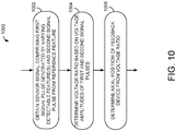
- Fig. 10 illustrates a method 1000 for measuring an axial position of a feedback device, as implemented by the measuring circuit 222, for example in part or in whole by the computing device 900.
- the sensor signal is received.
- the feedback device 204 comprises one or more varying detectable features (provided by varying the geometry or magnetic permeability of one or more position markers 202) that cause a change in a voltage amplitude of the sensor signal as a function of a relative axial position between the sensor and the varying detectable feature(s).
- the feedback device 204 also comprises a reference feature that result in the sensor signal's voltage amplitude remaining substantially constant upon the sensor 212 detecting passage of the reference feature.
- a sensor signal comprising a first signal pulse generated by the varying detectable feature(s) and a second signal pulse generated by the reference feature is obtained.
- a voltage ratio is then determined at step 1006, based on the voltage amplitudes of the first and second signal pulses. For this purpose, equations (1) and (3) or (1) and (4) above may be used, depending on whether the difference in voltage amplitude is linear or non-linear.
- the axial position of the feedback device may then be determined from the voltage ratio (e.g., using a look-up table as described above).
- the methods and systems described herein may be implemented in a high level procedural or object oriented programming or scripting language, or a combination thereof, to communicate with or assist in the operation of a computer system, for example the computing device 900.
- the methods and systems may be implemented in assembly or machine language.
- the language may be a compiled or interpreted language.
- Program code for implementing the methods and systems for detection may be stored on a storage media or a device, for example a ROM, a magnetic disk, an optical disc, a flash drive, or any other suitable storage media or device.
- the program code may be readable by a general or special-purpose programmable computer for configuring and operating the computer when the storage media or device is read by the computer to perform the procedures described herein.
- Embodiments of the methods and systems may also be considered to be implemented by way of a non-transitory computer-readable storage medium having a computer program stored thereon.
- the computer program may comprise computer-readable instructions which cause a computer, or in some embodiments the processing unit 902 of the computing device 900, to operate in a specific and predefined manner to perform the functions described herein.
- Computer-executable instructions may be in many forms, including program modules, executed by one or more computers or other devices.
- program modules include routines, programs, objects, components, data structures, etc., that perform particular tasks or implement particular abstract data types.
- functionality of the program modules may be combined or distributed as desired in various embodiments.
Landscapes
- Engineering & Computer Science (AREA)
- Physics & Mathematics (AREA)
- General Physics & Mathematics (AREA)
- Aviation & Aerospace Engineering (AREA)
- Manufacturing & Machinery (AREA)
- Transportation (AREA)
- Measurement Of Length, Angles, Or The Like Using Electric Or Magnetic Means (AREA)
Abstract
Description
- The present disclosure relates generally to engines, and more specifically to determining the axial position of feedback devices used in engines.
- Some feedback systems for featherable aircraft propellers use a feedback device that rotates with the engine to accurately measure the propeller blade pitch (or beta) angle and ensure that the blade angle is controlled according to the engine power set-point requested, such as in reverse and low pitch situations. A sensor can be used to measure the rotation of the feedback device via readable markers disposed on a surface of the feedback device, providing a proxy value for the rotational velocity of the engine, as well as to measure blade angle. Still, if the axial position of the feedback device is not accurately determined, the precision of the feedback system may be limited.
- Therefore, improvements are needed.
- In accordance with an aspect of the present invention, there is provided a method for determining an axial position of a feedback device, the feedback device coupled to rotate with an aircraft-bladed rotor about a longitudinal axis and to move along the axis with adjustment of a blade pitch angle of the rotor. The method comprises obtaining, from at least one sensor positioned adjacent the feedback device, a sensor signal comprising a first signal pulse having a first voltage amplitude and a second signal pulse having a second voltage amplitude greater than or substantially equal to the first voltage amplitude, the feedback device comprising at least one varying detectable feature configured to generate the first signal pulse and a reference feature configured to generate the second signal pulse, the at least one varying detectable feature configured to cause a change in the first voltage amplitude as a function of the axial position of the feedback device along the axis, determining a voltage ratio based on the first voltage amplitude and the second voltage amplitude, and determining the axial position of the feedback device from the voltage ratio.
- In an embodiment, the second signal pulse is generated by the reference feature being configured to cause the second voltage amplitude to remain substantially constant regardless of the axial position of the feedback device.
- In an embodiment according to any of the previous embodiments, the method further comprises determining a difference between the second voltage amplitude and the first voltage amplitude, the voltage ratio determined based on the difference in voltage amplitude.
- In an embodiment according to any of the previous embodiments, the difference in voltage amplitude is determined as Vdelta = Vpk-pk2 - Vpk-pk1, and the voltage ratio is determined as Vratio = Vdelta / Vpk-pk2 = (Vpk-pk2 - Vpk-pk1) / Vpk-pk2, where Vdelta is the difference in voltage amplitude, Vpk-pk2 is the second voltage amplitude, Vpk-pk1 is the first voltage amplitude, and Vratio is the voltage ratio.
- In an embodiment according to any of the previous embodiments, the difference in voltage amplitude is determined as Vdelta = Vpk-pk2 - Vpk-pk1, and the voltage ratio is determined as Vratio = Vdelta / (Vpk-pk1 + Vpk-pk2) = (Vpk-pk2 - Vpk-pk1) / (Vpk-pk1 + Vpk-pk2), where Vdelta is the difference in voltage amplitude, Vpk-pk2 is the second voltage amplitude, Vpk-pk1 is the first voltage amplitude, and Vratio is the voltage ratio.
- In an embodiment according to any of the previous embodiments, the first signal pulse is generated by the at least one varying detectable feature comprising at least one position marker having varying magnetic permeability.
- In an embodiment according to any of the previous embodiments, the first signal pulse is generated by the at least one varying detectable feature comprising at least one position marker having an axially varying dimension configured for causing the change in the first voltage amplitude as a function of the axial position of the feedback device.
- In an embodiment according to any of the previous embodiments, the first signal pulse is generated by the at least one varying detectable feature having a height smaller than a height of the reference feature for causing the second voltage amplitude to be greater than the first voltage amplitude.
- In an embodiment according to any of the previous embodiments, determining the axial position of the feedback device from the voltage ratio comprises inputting the voltage ratio into a look-up table and outputting the axial position from the look-up table.
- In accordance with another aspect of the present invention, there is provided a system for determining an axial position of a feedback device, the feedback device coupled to rotate with an aircraft-bladed rotor about a longitudinal axis and to move along the axis with adjustment of a blade pitch angle of the rotor. The system comprises at least one varying detectable feature and a reference feature provided on the feedback device, at least one sensor positioned adjacent the feedback device and configured for generating a sensor signal comprising a first signal pulse having a first voltage amplitude and a second signal pulse having a second voltage amplitude greater than or substantially equal to the first voltage amplitude, the first signal pulse generated upon the at least one sensor detecting passage of the at least one varying detectable feature as the feedback device rotates and moves about the axis and the second signal pulse generated upon the at least one sensor detecting passage of the reference feature as the feedback device rotates and moves about the axis, the at least one varying detectable feature configured to cause a change in the first voltage amplitude as a function of the axial position of the feedback device along the axis, and a measuring circuit coupled to the at least one sensor and configured for obtaining the sensor signal from the at least one sensor, determining a voltage ratio based on the first voltage amplitude and the second voltage amplitude, and determining the axial position of the feedback device from the voltage ratio.
- In an embodiment, the reference feature is configured to cause the second voltage amplitude to remain substantially constant regardless of the axial position of the feedback device.
- In an embodiment according to any of the previous embodiments, the measuring circuit is further configured for determining a difference between the second voltage amplitude and the first voltage amplitude, and for determining the voltage ratio based on the difference in voltage amplitude.
- In an embodiment according to any of the previous embodiments, the measuring circuit is configured for determining the difference in voltage amplitude as Vdelta = Vpk-pk2 - Vpk-pk1, and the measuring circuit is configured for determining the voltage ratio as Vratio = Vdelta / Vpk-pk2 = (Vpk-pk2 - Vpk-pk1) / Vpk-pk2, where Vdelta is the difference in voltage amplitude, Vpk-pk2 is the second voltage amplitude, Vpk-pk1 is the first voltage amplitude, and Vratio is the voltage ratio.
- In an embodiment according to any of the previous embodiments, the measuring circuit is configured for determining the difference in voltage amplitude as Vdelta = Vpk-pk2 - Vpk-pk1, and the measuring circuit is configured for determining the voltage ratio as Vratio = Vdelta / (Vpk-pk1 + Vpk-pk2) = (Vpk-pk2 - Vpk-pk1) / (Vpk-pk1 + Vpk-pk2), where Vdelta is the difference in voltage amplitude, Vpk-pk2 is the second voltage amplitude, Vpk-pk1 is the first voltage amplitude, and Vratio is the voltage ratio.
- In an embodiment according to any of the previous embodiments, the at least one varying detectable feature comprises at least one position marker having varying magnetic permeability.
- In an embodiment according to any of the previous embodiments, the at least one varying detectable feature comprises at least one position marker configured to vary axially across a top surface thereof for causing the change in the first voltage amplitude as a function of the axial position of the feedback device.
- In an embodiment according to any of the previous embodiments, the at least one varying detectable feature comprises at least one position marker configured to vary axially across at least one side surface thereof for causing the change in the first voltage amplitude as a function of the axial position of the feedback device.
- In an embodiment according to any of the previous embodiments, the at least one varying detectable feature and the reference feature are provided on a same position marker of the feedback device.
- In an embodiment according to any of the previous embodiments, the at least one varying detectable feature is provided on a first position marker of the feedback device and the reference feature is provided on a second position marker of the feedback device, the first and the second position marker circumferentially spaced about a surface of the feedback device.
- In accordance with yet another aspect of the present invention, there is provided a non-transitory computer readable medium having stored thereon program instructions executable by a processing unit for determining an axial position of a feedback device, the feedback device coupled to rotate with an aircraft-bladed rotor about a longitudinal axis and to move along the axis with adjustment of a blade pitch angle of the rotor. The program instructions are configured for obtaining, from at least one sensor positioned adjacent the feedback device, a sensor signal comprising a first signal pulse having a first voltage amplitude and a second signal pulse having a second voltage amplitude greater than or substantially equal to the first voltage amplitude, the feedback device comprising at least one varying detectable feature configured to generate the a first signal pulse and a reference feature configured to generate the second signal pulse, the at least one varying detectable feature configured to cause a change in the first voltage amplitude as a function of the axial position of the feedback device along the axis, determining a voltage ratio based on the first voltage amplitude and the second voltage amplitude and determining the axial position of the feedback device from the voltage ratio.
- Features of the systems, devices, and methods described herein may be used in various combinations, in accordance with the embodiments described herein.
- Reference is now made to the accompanying figures in which:
-
FIG. 1 is a schematic cross-sectional view of an example gas turbine engine; -
FIG. 2 is a schematic diagram of an example feedback sensing system; -
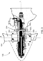
FIG. 3 is a schematic diagram of the propeller ofFIG. 1 showing the feedback device ofFIG. 2 , in accordance with one embodiment; -
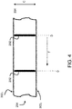
FIG. 4 is a schematic view of a surface of the feedback device ofFIG. 2 , with position markers provided thereon, in accordance with one embodiment; -
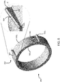
FIG. 5 is a schematic diagram of a feedback device having a varying detectable feature and a reference feature, in accordance with one embodiment; -
FIG. 6 is a schematic diagram of a feedback device having a varying detectable feature and a reference feature, in accordance with another embodiment; -
FIG. 7A is a plot of sensor output voltage as a function of an axial position of the feedback device ofFIG. 5 , upon detection of the varying detectable feature; -
FIG. 7B is a plot of sensor output voltage as a function of an axial position of the feedback device ofFIG. 5 , upon detection of the reference feature; -
FIG. 8 is a block diagram of an example measuring circuit, in accordance with another embodiment; -
FIG. 9 is a block diagram of an example computing device, in accordance with an embodiment; and -
FIG. 10 is a flowchart of a method for determining an axial position of a feedback device, in accordance with another embodiment. - It will be noted that throughout the appended drawings, like features are identified by like reference numerals.
-
FIG. 1 depicts agas turbine engine 110 of a type typically provided for use in subsonic flight. Theengine 110 comprises aninlet 112 through which ambient air is propelled, acompressor section 114 for pressurizing the air, acombustor 116 in which the compressed air is mixed with fuel and ignited for generating an annular stream of hot combustion gases, and aturbine section 118 for extracting energy from the combustion gases. - The
turbine section 118 comprises acompressor turbine 120, which drives the compressor assembly and accessories, and at least one power orfree turbine 122, which is independent from thecompressor turbine 120 and rotatingly drives a rotor shaft (also referred to herein as a propeller shaft or an output shaft) 124 about a propeller shaft axis 'A' through a reduction gearbox (RGB) 126. Hot gases may then be evacuated throughexhaust stubs 128. The gas generator of theengine 110 comprises thecompressor section 114, thecombustor 116, and theturbine section 118. - A rotor, in the form of a
propeller 130 through which ambient air is propelled, is hosted in apropeller hub 132. The rotor may, for example, comprise thepropeller 130 of a fixed-wing aircraft, or a main (or tail) rotor of a rotary-wing aircraft such as a helicopter. Thepropeller 130 may comprise a plurality of circumferentially-arrangedblades 134 connected to a hub by any suitable means and extending radially therefrom. Theblades 134 are also each rotatable about their own radial axes through a plurality of blade angles, which can be changed to achieve modes of operation, such as feather, full reverse, and forward thrust. - With reference to
FIG. 2 , afeedback sensing system 200 for pitch-adjustable blades of bladed rotors of aircraft will now be described. Thesystem 200 may be used for sensing a feedback device (also referred to as a feedback ring or phonic wheel) 204 of an aircraft propeller. As will be described further below, in one embodiment, the feedback device has multiple readable markers disposed on a surface thereof, and a sensor positioned adjacent the feedback device can be used to measure the rotation of the feedback device via the markers, providing a proxy value for the rotational velocity of the engine, as well as measure blade angle. It should however be understood that, although thesystem 200 is described and illustrated herein with reference to an aircraft propeller, such as thepropeller 130 ofFIG. 1 , thesystem 200 may apply to other types of rotors, such as those of helicopters. The systems and methods described herein are therefore not limited to being used for aircraft propellers. - In some embodiments, the
system 200 provides for detection and measurement of rotational velocity of one or more rotating elements of theengine 110 and of propeller blade angle on propeller systems, such as thepropeller 130 ofFIG. 1 . Thesystem 200 may interface to existing mechanical interfaces of typical propeller systems to provide a digital detection for electronic determination of the propeller blade angle. It should be noted that although the present disclosure focuses on the use of thesystem 200 and thefeedback device 204 in gas-turbine engines, similar techniques can be applied to other types of engines, including, but not limited to, electric engines and hybrid electric propulsion systems having a propeller driven in a hybrid architecture (series, parallel, or series/parallel) or turboelectric architecture (turboelectric or partial turboelectric). - The
system 200 comprises anannular member 204 and one ormore sensors 212 positioned proximate theannular member 204. Annular member 204 (referred to herein as a feedback device) has a plurality of circumferentially-spaced apart and detectable features (also referred to as position markers) 202 disposed thereon for detection by sensor(s) 212. In some embodiments, thedetectable features 202 and sensor(s) 212 may be disposed on a radially-outer side offeedback device 204. Alternatively,detectable features 202 and sensor(s) 212 could be disposed on a radially-inner side offeedback device 204. Severaldetectable features 202 may be spaced equiangularly about the perimeter (also referred to herein as the 'circumference') of thefeedback device 204. Other embodiments may apply. - In one embodiment, the one or
more sensors 212 are fixedly mounted to a static portion of theengine 110. In other embodiments, the one ormore sensors 212 are mounted for rotation withpropeller 130 and to move axially with adjustment of the blade angle of the blades of thepropeller 130, and thefeedback device 204 is fixedly mounted to a static portion of theengine 110. - In some embodiments, the
feedback device 204 is mounted for rotation withpropeller 130 and to move axially along rotation axis A to a plurality of axial positions, with adjustment of the blade angle of the blades of thepropeller 130. An axial position of thefeedback device 204 may then correspond to a respective angular (pitch) position of the blades and theposition markers 202 may be useful for detecting the axial position of thefeedback device 204 as thefeedback device 204 andbladed rotor 130 rotate. Thefeedback device 204 may therefore be useful for detecting the angular position of the adjustable blades by way of correlation. - The
system 200 also includes acontrol unit 220 communicatively coupled to the one ormore sensors 212. The sensor(s) 212 are configured for producing a sensor signal which is transmitted to or otherwise received by thecontrol unit 220, for example via a measuringcircuit 222 thereof. The sensor signal can be an electrical signal, digital or analog, or any other suitable type of signal. In some embodiments, the sensor(s) 212 produce a signal pulse in response to detecting the presence of aposition marker 202 in a sensing zone of thesensor 212. For example, thesensor 212 is an inductive sensor that operates on detecting changes in magnetic flux, and has a sensing zone which encompasses a circular or rectangular area or volume in front of thesensor 212. Theposition markers 202 provided on thefeedback device 204 may then be made of any suitable material which would cause the passage of theposition markers 202 near the sensor(s) 212 to provide a change in magnetic permeability within the magnetic field generated by thesensor 212. When aposition marker 202 is present in the sensing zone, or passes through the sensing zone during rotation of thefeedback device 204, the magnetic flux in the sensing zone is varied by the presence of the position marker 202 (in other words, a change in magnetic permeability occurs), and the sensor(s) 212 can produce a signal pulse, which forms part of the sensor signal. It should be understood that thesensor 212 may be any suitable sensor other than an inductive sensor, including, but not limited to, a Hall sensor and a variable reluctance sensor. - In the example illustrated in
FIG. 2 , a side view of a portion offeedback device 204 andsensor 212 is shown. Thesensor 212 is mounted to aflange 214 of a housing (for example of the reduction gearbox 126), so as to be positioned adjacent the plurality ofposition markers 202, which may extend away from thefeedback device 204 and towards thesensor 212. Thesensor 212 may be mounted at any suitable angle relative to theposition markers 202. In some embodiments, thesensor 212 is secured to thepropeller 130 so as to extend away from theflange 214 and towards theposition markers 202 along a radial direction, identified inFIG. 2 as direction 'R'.Sensor 212 andflange 214 may be fixedly mounted, for example to the housing of thereduction gearbox 126, or to any other static element of theengine 110, as appropriate. - In some embodiments, a
single sensor 212 is mounted in close proximity to thefeedback device 204 and theposition markers 202. In some other embodiments, in order to provide redundancy as well as multiple signal sources at different axial locations, one or more additional sensors, which may be similar to thesensor 212, are provided. In particular, it may be desirable to use multiple sensors when the axial distance (i.e. the distance along axis A) travelled by thefeedback device 204 is too large for the range of thesensors 212. It should be understood that any suitable number ofsensors 212 may apply and the number ofsensors 212 and their positions may be optimized according to the specifics of the application. - With additional reference to
FIG. 3 , in some embodiments thefeedback device 204 is embodied as a circular disk (or annular member) which rotates as part of theengine 110, for example with thepropeller shaft 124 or with thepropeller 130. Thefeedback device 204 comprises opposing faces (not shown) having outer edges 3021, 3022 and defines an exposed surface (also referred to as a "root surface") 304 which extends between the opposing faces and circumscribes them. Put differently, thesurface 304 of thefeedback device 204 is the periphery of the circular disk which spans between the two opposing faces and theroot surface 304 intersects the faces at the edges 3021, 3022. Theposition markers 202 are illustratively provided on the surface 304 (in a manner that will be discussed in further detail below) and thesensor 212 is configured to be positioned adjacent thesurface 304 to detect passage of theposition markers 202. As discussed above, in some embodiments, thesurface 304 is a radially-outer side of thefeedback device 204 whereas in other embodiments, thesurface 304 is a radially-inner side offeedback device 204. - The
position markers 202 may be manufactured separately from thefeedback device 204 and attached thereto using any suitable technique, such as welding or the like. Aposition marker 202 can then be a portion of thefeedback device 204 which is made of a different material, or to which is applied a layer of a different material. Theposition markers 202 may then be applied to thesurface 304, for instance as strips of metal or other material for detection by thesensor 212. - With continued additional reference to
FIG. 3 , thefeedback device 204 is supported for rotation with thepropeller 130, which rotates about the longitudinal axis A. Thefeedback device 204 is also supported for longitudinal sliding movement along the axis A (in the direction of arrow C), e.g. by support members, such as a series of circumferentially spacedfeedback rods 306 that extend along the axis A. Acompression spring 308 surrounds an end portion of eachrod 306. - As depicted in
FIG. 3 , thepropeller 130 comprises a plurality of angularly arrangedblades 134, each of which is rotatable about a radially-extending axis 'R' through a plurality of adjustable blade angles, the blade angle being the angle between the chord line (i.e. a line drawn between the leading and trailing edges of the blade) of the propeller blade section and a plane perpendicular to the axis of propeller rotation. In some embodiments, thepropeller 130 is a reversing propeller, capable of operating in a variety of modes of operation, including feather, full reverse, and forward thrust. Depending on the mode of operation, the blade angle may be positive or negative: the feather and forward thrust modes are associated with positive blade angles, and the full (or maximum) reverse mode is associated with negative blade angles. - Referring now to
FIG. 4 in addition toFIG. 2 andFIG. 3 , thefeedback device 204 illustratively comprises position markers 202 (referred to herein as "straight" markers), which may, in one embodiment be arranged along a direction 'D' that is substantially transverse to the opposing edges 3021, 3022 (i.e. substantially parallel to the axis A ofFIG. 3 ). Although only twomarkers 202 are illustrated, it should be understood that any suitable number ofmarkers 202 may be present across the whole of thesurface 304. In one embodiment, themarkers 202 may be substantially equally spaced from one another on thesurface 304. In addition, themarkers 202 may, in some embodiments, be of substantially a common shape and size, for example having a common volumetric size. Still, other embodiments are considered. - The signal pulses produced by the
sensor 212, which form part of the electrical signal received by thecontrol unit 220, can be used to determine various operating parameters of theengine 110 and thepropeller 130. In particular, the sensor signal generated by thesensor 212 illustratively comprises a series of pulses generated in response to detecting themarkers 202. The spacing of the markers 202 (which may, or may not, be regular) can, for example, be used to determine a speed of rotation of thefeedback device 204 and/or a blade angle of thepropeller 130. - With continued reference to
FIG. 2 ,FIG. 3 , andFIG. 4 , as thefeedback device 204 rotates, varying portions thereof enter, pass through, and then exit the sensing zone of the one ormore sensors 212. From the perspective of the sensor(s) 212, thefeedback device 204 moves axially along axis A (in the direction of arrow C, referred to herein as the "axial direction") and rotates about direction 'F'. In particular, with axial travel of thefeedback device 204, the one ormore sensors 212 are positioned adjacent to different portions of thefeedback device 204. Thesensor 212 is adjacent the edge 3022 (also referred to as the 'engine side') when the propeller (reference 130 inFigure 1 ) is in a fine (or lower) pitch position. When thepropeller 130 is in the maximum reverse condition, thesensor 212 is adjacent the edge 3021 (also referred to as the 'propeller side'). The longitudinal (or beta) position (along axis A) of thefeedback device 204 relative to thesensor 212 therefore varies with movement of thefeedback ring 204. - In order to improve the accuracy of the
feedback system 200, it is proposed herein to determine the axial position of thefeedback device 204 based on voltage. In one embodiment, the systems and methods described herein may be used to accurately determine the axial position of thefeedback device 204, and accordingly compute the corresponding blade angle for the propeller (reference 130 inFIG. 1 ) for use in controlling the propeller. For this purpose and as will be discussed further below, thefeedback device 204 is configured to comprise a reference (or "index") feature, which generates a substantially constant (or equal) signal pulse as the feedback device translates along the axial direction, and at least one varying detectable feature, which causes a change in the voltage amplitude of the sensor signal (i.e. in the voltage amplitude of the signal pulses produced by the sensor 212) as a function of an axial position of thefeedback device 204. - The reference feature may be provided as a
position marker 202 having a substantially constant geometry, namely a substantially constant dimension (i.e. height) across the axial direction and a substantially constant dimension (i.e. width or thickness) across the direction substantially perpendicular to the axial direction, as will be discussed further below. A speed marker (not shown), e.g. an additional index feature specifically used for speed sensing, may alternatively be used as the reference feature. Still, it should be understood that, in order to have an equally-spaced andbalanced feedback device 204, it may be desirable to use aposition marker 202 as the reference feature. - In some embodiments, the varying detectable feature(s) are provided by varying the geometry of one or
more position markers 202. The geometry may be varied across the axial direction (i.e. along the rotational axis A), such that a detectable change in the voltage amplitude of the sensor signal is obtained as thefeedback device 204 moves axially along the axis A. In particular, the change in voltage amplitude is detected upon passage of the varying detectable feature(s) in the sensing zone of thesensor 212 and can then be correlated to the axial positon. - The geometry modification may consist in a gradual change (e.g., increase or decrease) in the height or shape of the given
position marker 202, provided the geometry modification results in a detectable change in signal as the feedback device 204 (and accordingly the given position marker 202) moves axially. For example, a varying detectable feature may be achieved by providing a sloped surface on a givenposition marker 202. In the embodiment illustrated inFIG. 5 , the reference feature 5022 comprises a position marker of substantially constant dimensions (i.e., height and width) along the axial direction (indicated as direction 'E' inFIG. 5 ) and the direction (not shown) substantially perpendicular thereto and the varying detectable feature 5021 is achieved by providing a slope on atop surface 504 of theposition marker 202. The slopedtop surface 504 then changes the voltage amplitude as the feedback device 204 (and accordingly the position marker 202) moves axially. -
FIG. 5 illustrates that the varying detectable feature 5021 is achieved by gradually increasing the height (i.e. the distance between theupper surface 504 and the root surface 304) of theposition marker 202, from a first end 5081 thereof (provided adjacent the edge 3021) to a second end 5082 (provided adjacent the edge 3022) opposite the first end 5081. Thus, the varying detectable feature 5021 may be configured such that the height of theposition marker 202 is the lowest when the propeller is in the reverse position and the highest when the propeller is in the low pitch condition. Although not illustrated, it should however be understood that the position marker's height may alternatively be reduced from the first end 5081 to the second end 5082, such that the position marker's height is the lowest in the fine pitch condition and the highest in the reverse condition. Still, because the reading error (also referred to as "beta error") that may be experienced by thefeedback sensing system 200 is typically greater in the reverse condition, it may be desirable to ensure that the position marker's height is the lowest in the fine pitch condition and the highest in the reverse condition. This may in turn improve system accuracy. Indeed, when the position marker's height is the highest, theposition marker 202 is positioned closer to thesensor 212, which improves the sensor signal. - It should also be understood the first and second ends 5081, 5082 of the varying detectable feature 5021 need not be provided adjacent the respective edge 3021, 3022 of the
feedback device 204 but may extend beyond the edges 3021, 3022. Moreover, in some embodiments, the varying detectable feature 5021 may be achieved by providing a slope on one or more side surfaces 508 of the position marker 202 (e.g., in addition to or as an alternative to providing a slope on the upper surface 504). In addition, the slope of the position marker's surface (e.g., 504, 508) may be linear or non-linear. In some embodiments, the position marker's surface is sloped along a single direction, namely along the rotational axis A. In other embodiments, the surface is sloped along two or more directions, for example along the rotational axis A and along a direction substantially perpendicular to the rotational axis A. Other embodiments may also apply. - As illustrated in
FIG. 5 , the varying detectable feature(s) as in 5021 and the reference feature as in 5022 may be provided on separate position markers as in 202 and circumferentially spaced about a surface of the feedback device 204 (i.e. provided at various radial positions). Alternatively and as illustrated inFIG. 6 , asingle position marker 602 may comprise both the varying detectable feature(s) and the reference feature. In particular, as shown inFIG. 6 , thesame position marker 602 may comprise a first section 6041, which has a varying geometry and constitutes the varying detectable feature, and a second section 6042, which is adjacent the first section 6041, has a substantially constant geometry, and constitutes the reference feature. The varying geometry of the first section 6041 may be achieved by providing the first section 6041 with asloped surface 606. In the embodiment ofFIG. 6 , thesloped surface 606 is a side surface of theposition marker 602. It should however be understood that both side surfaces of theposition marker 602 may be sloped or chamfered. It should also be understood that thetop surface 608 of theposition marker 602 may alternatively (or additionally) be sloped. The substantially constant geometry of the second section 6042 may be achieved by providing the second section 6042 with dimensions (i.e., height and width) that remain substantially constant along the axial direction (indicated as direction 'E' inFIG. 6 ) and the direction (not shown) substantially perpendicular thereto. In other words, neither thetop surface 610 nor the side surfaces 612 of the second section 6042 are sloped and the second section 6042 has a substantially cuboid shape. - It should also be understood that the change (e.g., increment) in the marker's dimensions (e.g., width) may be limited by the length (e.g., the dimension along the axial axis A) of the
feedback device 204. It may also be desirable for the change in the marker's width to be such that, at no point along the axial direction, does the marker's width exceed the width (or thickness) of the head (not shown) ofsensor 212. In this manner, accuracy of thefeedback system 200 can be ensured. - Although the varying detectable feature(s) (as in 5021 in
FIG. 5 or 602 inFIG. 6 ) are illustrated and described herein as having an axially varying slope, it should be understood that the varying detectable feature(s) as in 5021 may alternatively have an axially varying curve (not shown) and that the curve may be linear or non-linear. Other embodiments may apply. - Although
FIG. 5 andFIG. 6 illustrate the varying detectable feature(s) as being achieved by varying the geometry of the position marker(s) as in 202, it should be understood that, in other embodiments, the varying detectable feature(s) may be achieved by varying the magnetic permeability of one ormore position markers 202. Indeed, aposition marker 202 of varying permeability along the rotational axis A will also cause the signal strength of thesensor 212 to vary as a function of axial position. As such, theposition markers 202 may be configured such that their magnetic permeability gradually varies (e.g., gradually increases or decreases) along the direction of axial travel of thefeedback device 204. This may be achieved by providing afeedback device 204 comprising two or more materials having different magnetic permeability. Other suitable geometric and/or material-based parameters of theposition markers 202 may be used to induce the change in the voltage amplitude of the sensor signal as a function of axial position. - In addition, although a single varying detectable feature is described and illustrated in
FIG. 5 andFIG. 6 , it should be understood that any suitable number of varying detectable features may be provided on thefeedback device 204, that the varying detectable feature(s) may be provided on straight markers, and that the varying detectable features may have any suitable configuration, shape, size, and orientation. In one embodiment, allposition markers 202 may be configured to have varying detectable features. It should however be understood that, in other embodiments, only selectedposition markers 202 may have varying detectable features. It should also be understood that the number of varying detectable features that are provided on thefeedback device 204 may depend on factors including, but not limited to, engine and/or feedback device configuration and required accuracy for thefeedback sensing system 200. Indeed, providing an increased number of varying detectable features may allow to increase the resolution (i.e. increase the number of signal pulses per revolution of the feedback device 204), and accordingly improve accuracy of the axial position measurement. The number of varying detectable features and of reference feature(s) may therefore be optimized for the rotational speed of thefeedback device 204. - Referring now to
FIG. 7A and FIG. 7B , as described herein, thefeedback device 204 is designed such that the geometry of the varying detectable feature(s) that pass the sensor (reference 212) inFIG. 2 in the axial direction produce a change in the voltage amplitude of the sensor signal pulses. In the embodiments ofFIG. 7A and FIG. 7B , the voltage amplitude of the sensor signal pulses is represented as a peak-to-peak voltage amplitude (e.g., Vpk-pk). It should however be understood that the voltage amplitude may be represented as an average voltage amplitude, a root mean square (RMS) voltage amplitude (e.g., Vrms), or a peak voltage amplitude. Still, it may be desirable to use the peak-to-peak voltage amplitude (rather than the average, RMS, or peak voltage amplitude) because such a measure may provide a larger difference in voltage amplitude (Vdelta, discussed further below), which may in turn improve system accuracy. - In the embodiment of
FIG. 7A and FIG. 7B , the varying detectable feature 5021 extends axially (e.g., along the direction of axis A, as illustrated inFIG. 5 ), from a first end (illustrated as P1) to a second end (illustrated as P3), and has a gradually increasing height along the axial direction, from P1 to P3, reaching the highest point h1. As discussed above, P1 may correspond to the reverse condition and P3 to the fine pitch condition. The changing geometry (e.g. slope) of the varying detectable feature 5021 causes the peak-to-peak voltage amplitude Vpk-pk1 of the signal pulse generated by passage of the varying detectable feature 5021 in the sensing zone of thesensor 212 to increase, from P1 to P3, as thefeedback device 204 moves axially (in the direction of arrow C). In particular, the peak-to-peak voltage amplitude Vpk-pk1 is smallest (or minimum) at P1 and largest (or maximum) at P3, and in between its minimum and maximum values at P2. InFIG. 7A , P2 is illustrated as being substantially mid-point between P1 and P3. It should however be understood that the increase in voltage amplitude may not be linear and the voltage amplitude may not be midway between the minimum and maximum values at P2. - Conversely, the reference feature 5022, which also extends axially (e.g., along the direction of axis A, as illustrated in
FIG. 5 ) from a first end (illustrated as P'1 inFIG. 7B ) to a second end (illustrated as P'3 inFIG. 7B ) and has a substantially constant height h2 along the axial direction, i.e. from P'1, to P'2 (substantially mid-point between P'1 and P'3) and P'3. The substantially constant geometry of the reference feature 5022 causes the peak-to-peak voltage amplitude Vpk-pk2 of the signal pulse generated by passage of the reference feature 5022 in the sensing zone of thesensor 212 to remain substantially constant, from P'1 to P'3, as thefeedback device 204 moves axially. InFIG. 5A and FIG. 5B , the axial movement of thefeedback device 204 is illustrated by arrow C for sake of clarity. It should however be understood that thefeedback device 204 moves axially in both directions (i.e. in the direction of arrow C and in the direction opposite thereto, not shown). - In addition, in one embodiment, the reference feature 5022 is configured such that the height h2 is greater than the height of the varying detectable feature 5021 at any point along the axial direction. In other words, h2 is greater than h1 at P3, where the heights of the varying detectable feature 5021 and the reference feature 5022 are maximum. In this manner, at any point along the axial direction, the peak-to-peak voltage amplitude Vpk-pk2 of the signal pulse generated by passage of the reference feature 5022 remains higher than the peak-to-peak voltage amplitude Vpk-pk1 of the signal pulse generated by passage of the varying detectable feature 5021.
- In order to determine the axial position of the
feedback device 204, the voltage difference (Vdelta) between the two voltage amplitudes Vpk-pk2 and Vpk-pk1 may first be computed as:
- From equation (1), it can be seen that, in one embodiment, the
feedback device 204 being configured such that the peak-to-peak voltage amplitude Vpk-pk2 remains greater than the peak-to-peak voltage amplitude Vpk-pk1 may prevent the voltage difference (Vdelta) from being equal to zero at any point along the axial direction (including P3). In turn, this may allow to readily differentiate between the farthest axial position of the feedback device 204 (i.e. the position at P3) and a system malfunction or error. - It should however be understood that, in other embodiments, the
feedback device 204 may be configured such that, at point P3, the height h1 of the varying detectable feature 5021 is substantially equal to the height h2 of the reference feature 5022. In this manner, at P3, the peak-to-peak voltage amplitude Vpk-pk2 is substantially equal to the peak-to-peak voltage amplitude Vpk-pk1. However, this would lead to the voltage difference (Vdelta) being substantially equal to zero at P3, resulting in an inability to differentiate between the farthest axial position of the feedback device 204 (i.e. the position at P3) and a malfunction or error. - In one embodiment, as the
feedback device 204 translates axially towards reverse (from P3 towards P1), the increasingly smaller height of the varying detectable feature 5021 causes the sensor signal to have decreasingly lower voltage amplitude Vpk-pk1, such that the voltage difference (Vdelta) between voltage the amplitudes Vpk-pk2 and Vpk-pk1 is larger. Conversely, as thefeedback device 204 translates axially towards fine pitch (from P1 towards P3), the increasingly larger height of the varying detectable feature 5021 causes the sensor signal to have increasingly higher voltage amplitude Vpk-pk1, such that the voltage difference (Vdelta) between the voltage amplitudes Vpk-pk2 and Vpk-pk1 is smaller. This can be expressed as:
- The value of Vdelta illustratively increases or decreases as a function of the relative difference in geometry between the varying detectable feature 5021 and the reference feature 5022, allowing for the axial position of the
feedback device 204 to be identified. The axial position may indeed be determined from a voltage ratio (Vratio), e.g. using a look-up table that correlates the voltage ratio (Vratio) to the axial position. For instance, the voltage ratio may be input into the look-up table and the axial position output from the look-up table - In one embodiment, using a voltage ratio (rather than an absolute voltage) computation may provide an improved means of determining the axial position of the
feedback device 204 where system variables such as tolerance stack-up do not influence the accuracy. The voltage ratio may be computed as:

- Equation (3) may be used in cases where the difference in voltage amplitude (Vdelta) is linear while equation (4) may be used when the difference in voltage amplitude (Vdelta) is non-linear.
- Since the voltage ratio (Vratio) changes across the axial position of the
feedback device 204, the voltage ratio represents the axial position. - Referring to
FIG. 8 , there is illustrated an example embodiment for the measuringcircuit 222. The sensor signal is received by the measuringcircuit 222 from thesensor 212. A voltageamplitude detection unit 802 receives the sensor signal and determines the voltage amplitudes of the first and second signal pulses. As discussed above, the voltage amplitude of the signal pulses may be represented as a peak to voltage peak amplitude (e.g., Vpk-pk) or as an average voltage amplitude (e.g., Vrms). In some embodiments, the voltageamplitude detection unit 802 is a rectifier circuit, which may be a full wave or a half wave rectifier, depending on the geometry of thefeedback device 204. Alternatively, the voltageamplitude detection unit 802 is implemented in software, for example using a peak detection algorithm. Other circuits and/or algorithms may be used to obtain the voltage amplitude of the sensor signal. - The output of the voltage amplitude detection unit 802 (i.e. the voltage amplitudes of the first and second signal pulses) is then sent to a voltage
ratio computation unit 804, which computes the voltage ratio using equation (3) or (4) above. The voltage ratio may then be input to a look-up table 806 in order to determine axial position. It should be understood that the look-up table 806 may be replaced with software to apply known relationships/correlations from the voltage ratio to the axial position via equations. The relationships/correlations may be represented by linear or non-linear equations. Interpolation can be used to determine values that fall in between look-up table values. -
FIG. 9 is an example embodiment of acomputing device 900 for implementing thecontrol unit 220, and more particularly for performing some or all of the functions of the measuringcircuit 222, described above with reference toFIG. 2 . The measuringcircuit 222, or any other device configured for measuring the axial position of a feedback device as described herein, may be implemented with one ormore computing devices 900. For example, afirst computing device 900 may be used to implement the voltageamplitude detection unit 802 and asecond computing device 900 may be used to implement the voltageratio computation unit 804. Alternatively, a single computing device may be used to implement both the voltageamplitude detection unit 802 and the voltageratio computation unit 804. Other embodiments may also apply. - The
computing device 900 may form part or all of a Full Authority Digital Engine Control (FADEC), Electronic Engine Control (EEC), Engine Control Unit (ECU), electronic propeller control (EPEC), propeller control unit (PCU), and the like. - The
computing device 900 comprises aprocessing unit 902 and amemory 904 which has stored therein computer-executable instructions 906. Theprocessing unit 902 may comprise any suitable devices configured to cause a series of steps to be performed such thatinstructions 906, when executed by thecomputing device 900 or other programmable apparatus, may cause the functions/acts/steps specified in the method described herein to be executed. Theprocessing unit 902 may comprise, for example, any type of general-purpose microprocessor or microcontroller, a digital signal processing (DSP) processor, a CPU, an integrated circuit, a field programmable gate array (FPGA), a reconfigurable processor, other suitably programmed or programmable logic circuits, or any combination thereof. - The
memory 904 may comprise any suitable known or other machine-readable storage medium. Thememory 904 may comprise non-transitory computer readable storage medium, for example, but not limited to, an electronic, magnetic, optical, electromagnetic, infrared, or semiconductor system, apparatus, or device, or any suitable combination of the foregoing. Thememory 904 may include a suitable combination of any type of computer memory that is located either internally or externally to device, for example random-access memory (RAM), read-only memory (ROM), electro-optical memory, magneto-optical memory, erasable programmable read-only memory (EPROM), and electrically-erasable programmable read-only memory (EEPROM), Ferroelectric RAM (FRAM) or the like.Memory 904 may comprise any storage means (e.g., devices) suitable for retrievably storing machine-readable instructions 906 executable by processingunit 902. -
Fig. 10 illustrates amethod 1000 for measuring an axial position of a feedback device, as implemented by the measuringcircuit 222, for example in part or in whole by thecomputing device 900. Atstep 1002, the sensor signal is received. As indicated above, thefeedback device 204 comprises one or more varying detectable features (provided by varying the geometry or magnetic permeability of one or more position markers 202) that cause a change in a voltage amplitude of the sensor signal as a function of a relative axial position between the sensor and the varying detectable feature(s). Thefeedback device 204 also comprises a reference feature that result in the sensor signal's voltage amplitude remaining substantially constant upon thesensor 212 detecting passage of the reference feature. - At
step 1004, a sensor signal comprising a first signal pulse generated by the varying detectable feature(s) and a second signal pulse generated by the reference feature is obtained. A voltage ratio is then determined atstep 1006, based on the voltage amplitudes of the first and second signal pulses. For this purpose, equations (1) and (3) or (1) and (4) above may be used, depending on whether the difference in voltage amplitude is linear or non-linear. At step 1008, the axial position of the feedback device may then be determined from the voltage ratio (e.g., using a look-up table as described above). - The methods and systems described herein may be implemented in a high level procedural or object oriented programming or scripting language, or a combination thereof, to communicate with or assist in the operation of a computer system, for example the
computing device 900. Alternatively, the methods and systems may be implemented in assembly or machine language. The language may be a compiled or interpreted language. Program code for implementing the methods and systems for detection may be stored on a storage media or a device, for example a ROM, a magnetic disk, an optical disc, a flash drive, or any other suitable storage media or device. The program code may be readable by a general or special-purpose programmable computer for configuring and operating the computer when the storage media or device is read by the computer to perform the procedures described herein. Embodiments of the methods and systems may also be considered to be implemented by way of a non-transitory computer-readable storage medium having a computer program stored thereon. The computer program may comprise computer-readable instructions which cause a computer, or in some embodiments theprocessing unit 902 of thecomputing device 900, to operate in a specific and predefined manner to perform the functions described herein. - Computer-executable instructions may be in many forms, including program modules, executed by one or more computers or other devices. Generally, program modules include routines, programs, objects, components, data structures, etc., that perform particular tasks or implement particular abstract data types. Typically the functionality of the program modules may be combined or distributed as desired in various embodiments.
- The above description is meant to be exemplary only, and one skilled in the art will recognize that changes may be made to the embodiments described without departing from the scope of the invention disclosed. Still other modifications which fall within the scope of the present invention will be apparent to those skilled in the art, in light of a review of this disclosure.
- Various aspects of the systems and methods described herein may be used alone, in combination, or in a variety of arrangements not specifically discussed in the embodiments described in the foregoing and is therefore not limited in its application to the details and arrangement of components set forth in the foregoing description or illustrated in the drawings. For example, aspects described in one embodiment may be combined in any manner with aspects described in other embodiments. Although particular embodiments have been shown and described, it will be apparent to those skilled in the art that changes and modifications may be made without departing from this invention in its broader aspects. The scope of the following claims should not be limited by the embodiments set forth in the examples, but should be given the broadest reasonable interpretation consistent with the description as a whole.
Claims (15)
- A method for determining an axial position of a feedback device (204), the feedback device (204) coupled to rotate with an aircraft-bladed rotor (130) about a longitudinal axis (A) and to move along the axis (A) with adjustment of a blade pitch angle of the rotor (130), the method comprising:obtaining, from at least one sensor (212) positioned adjacent the feedback device (204), a sensor signal comprising a first signal pulse having a first voltage amplitude (Vpk-pk1) and a second signal pulse having a second voltage amplitude (Vpk-pk2) greater than or substantially equal to the first voltage amplitude (Vpk-pk1), the feedback device (204) comprising at least one varying detectable feature (5021; 6041) configured to generate the first signal pulse and a reference feature (5022; 6042) configured to generate the second signal pulse, the at least one varying detectable feature (5021; 6041) configured to cause a change in the first voltage amplitude (Vpk-pk1) as a function of the axial position of the feedback device (204) along the axis (A);determining a voltage ratio based on the first voltage amplitude (Vpk-pk1) and the second voltage amplitude (Vpk-pk2); anddetermining the axial position of the feedback device (204) from the voltage ratio.
- The method of claim 1, wherein the second signal pulse is generated by the reference feature (5022; 6042) being configured to cause the second voltage amplitude (Vpk-pk2) to remain substantially constant regardless of the axial position of the feedback device (204).
- The method of claim 1 or 2, further comprising determining a difference between the second voltage amplitude (Vpk-pk2) and the first voltage amplitude (Vpk-pk1), the voltage ratio determined based on the difference in voltage amplitude.
- The method of claim 3, wherein the difference in voltage amplitude is determined as:


- The method of claim 3, wherein the difference in voltage amplitude is determined as:


- The method of any preceding claim, wherein the first signal pulse is generated by the at least one varying detectable feature (5021) comprising at least one position marker (202; 602) having varying magnetic permeability.
- The method of any of claims 1 to 5, wherein the first signal pulse is generated by the at least one varying detectable feature (5021; 6041) comprising at least one position marker (202; 602) having an axially varying dimension configured for causing the change in the first voltage amplitude (Vpk-pk1) as a function of the axial position of the feedback device (204), optionally wherein the first signal pulse is generated by the at least one varying detectable feature (5021) having a height smaller than a height of the reference feature (5022) for causing the second voltage amplitude (Vpk-pk2) to be greater than the first voltage amplitude (Vpk-pk1).
- The method of any preceding claim, wherein determining the axial position of the feedback device (204) from the voltage ratio comprises inputting the voltage ratio into a look-up table (806) and outputting the axial position from the look-up table (806).
- A system (200) for determining an axial position of a feedback device (204), the feedback device (204) configured to be coupled to rotate with an aircraft-bladed rotor (130) about a longitudinal axis (A) and to move along the axis (A) with adjustment of a blade pitch angle of the rotor (130), the system comprising:at least one varying detectable feature (5021; 6041) and a reference feature (5022; 6042) provided on the feedback device (204);at least one sensor (212) positioned adjacent the feedback device (204) and configured for generating a sensor signal comprising a first signal pulse having a first voltage amplitude (Vpk-pk1) and a second signal pulse having a second voltage amplitude (Vpk-pk2) greater than or substantially equal to the first voltage amplitude (Vpk-pk1), the first signal pulse generated upon the at least one sensor (212) detecting passage of the at least one varying detectable feature (5021; 6041) as the feedback device (204) rotates and moves about the axis (A) and the second signal pulse generated upon the at least one sensor (212) detecting passage of the reference feature (5022; 6042) as the feedback device (204) rotates and moves about the axis (A), the at least one varying detectable feature (5021; 6041) configured to cause a change in the first voltage amplitude (Vpk-pk1) as a function of the axial position of the feedback device (204) along the axis (A); anda measuring circuit (222) coupled to the at least one sensor (212) and configured for:obtaining the sensor signal from the at least one sensor (212),
determining a voltage ratio based on the first voltage amplitude (Vpk-pk1) and the second voltage amplitude (Vpk-pk2), anddetermining the axial position of the feedback device (204) from the voltage ratio. - The system (200) of claim 9, wherein the reference feature (5022; 6042) is configured to cause the second voltage amplitude (Vpk-pk2) to remain substantially constant regardless of the axial position of the feedback device (204).
- The system (200) of claim 9 or 10, wherein the measuring circuit (222) is further configured for determining a difference between the second voltage amplitude (Vpk-pk2) and the first voltage amplitude (Vpk-pk1), and for determining the voltage ratio based on the difference in voltage amplitude.
- The system (200) of claim 11, wherein the measuring circuit (222) is configured for determining the difference in voltage amplitude as:


- The system (200) of claim 11, wherein the measuring circuit (222) is configured for determining the difference in voltage amplitude as:


- The system (200) of any of claims 9 to 13, wherein:the at least one varying detectable feature (5021; 6041) comprises at least one position marker (202; 602) having varying magnetic permeability; and/orthe at least one varying detectable feature (5021) comprises at least one position marker (202) having an axially varying height for causing the change in the first voltage amplitude (Vpk-pk1) as a function of the axial position of the feedback device (204); and/orthe at least one varying detectable feature (6041) comprises at least one position marker (602) having an axially varying width for causing the change in the first voltage amplitude (Vpk-pk1) as a function of the axial position of the feedback device (204).
- The system (200) of any of claims 9 to 14, wherein:the at least one varying detectable feature (6041) and the reference feature (6042) are provided on a same position marker (602) of the feedback device (204); and/orthe at least one varying detectable feature (5021) is provided on a first position marker (202) of the feedback device (204) and the reference feature (5022) is provided on a second position marker (202) of the feedback device (204), the first and the second position marker (202) circumferentially spaced about a surface of the feedback device (204).
Applications Claiming Priority (1)
| Application Number | Priority Date | Filing Date | Title |
|---|---|---|---|
| US16/717,321 US11420772B2 (en) | 2019-12-17 | 2019-12-17 | System and method for determining an axial position of a feedback device |
Publications (2)
| Publication Number | Publication Date |
|---|---|
| EP3838745A1 true EP3838745A1 (en) | 2021-06-23 |
| EP3838745B1 EP3838745B1 (en) | 2022-11-09 |
Family
ID=73855366
Family Applications (1)
| Application Number | Title | Priority Date | Filing Date |
|---|---|---|---|
| EP20215047.0A Active EP3838745B1 (en) | 2019-12-17 | 2020-12-17 | System and method for determining an axial position of a feedback device |
Country Status (3)
| Country | Link |
|---|---|
| US (1) | US11420772B2 (en) |
| EP (1) | EP3838745B1 (en) |
| CA (1) | CA3101708A1 (en) |
Cited By (1)
| Publication number | Priority date | Publication date | Assignee | Title |
|---|---|---|---|---|
| EP4450916A1 (en) * | 2023-04-18 | 2024-10-23 | Pratt & Whitney Canada Corp. | System and method for measuring an axial position of a rotating component |
Families Citing this family (4)
| Publication number | Priority date | Publication date | Assignee | Title |
|---|---|---|---|---|
| US11428116B2 (en) * | 2019-11-29 | 2022-08-30 | Pratt & Whitney Canada Corp. | System and method for measuring an axial position of a rotating component of an engine |
| CN117734963B (en) * | 2024-02-19 | 2024-04-26 | 成都以太航空保障工程技术有限责任公司 | Helicopter rotor wing common taper detection method and device |
| US12372033B1 (en) | 2024-03-05 | 2025-07-29 | General Electric Company | Turbine engine with sound-based active control |
| US12359588B1 (en) | 2024-08-02 | 2025-07-15 | General Electric Company | Aircraft engine aeromechanical instability detection |
Citations (4)
| Publication number | Priority date | Publication date | Assignee | Title |
|---|---|---|---|---|
| EP0353076A2 (en) * | 1988-07-29 | 1990-01-31 | Dowty Rotol Ltd. | Assembly for determining the longitudinal displacement of a rotating shaft |
| US5748111A (en) * | 1996-03-29 | 1998-05-05 | Caterpillar Inc. | Apparatus for monitoring the speed and axial position of a rotating member |
| US20130094966A1 (en) * | 2010-07-06 | 2013-04-18 | Rolls-Royce Plc | Axial displacement and rotational speed monitoring |
| US20180050789A1 (en) * | 2016-08-17 | 2018-02-22 | Pratt & Whitney Canada Corp. | System and method for electronic propeller blade angle position feedback with angled pairs of teeth |
Family Cites Families (18)
| Publication number | Priority date | Publication date | Assignee | Title |
|---|---|---|---|---|
| GB8706905D0 (en) | 1987-03-24 | 1987-04-29 | Schlumberger Electronics Uk | Shaft monitoring system |
| US4934901A (en) | 1989-04-21 | 1990-06-19 | Duchesneau Jerome G | Pitch change actuation system |
| US5508609A (en) | 1993-06-30 | 1996-04-16 | Simmonds Precision Product Inc. | Monitoring apparatus for detecting axial position and axial alignment of a rotating shaft |
| US5913659A (en) | 1993-11-22 | 1999-06-22 | United Technologies Corporation | Apparatus and method for adjusting rotor blade tracking |
| US5897293A (en) | 1996-11-22 | 1999-04-27 | United Technologies Corporation | Counterweighted propeller control system |
| US6077040A (en) | 1998-05-01 | 2000-06-20 | United Technologies Corporation | Control system for blades for a variable pitch propeller |
| US6782766B2 (en) | 2002-09-13 | 2004-08-31 | Gastops Ltd. | Apparatus for detecting torque, axial position and axial alignment of a rotating shaft |
| EP1876422A1 (en) | 2006-07-05 | 2008-01-09 | Carl Freudenberg KG | Device for measuring rotational and translatory movements |
| ES2349816B1 (en) | 2009-05-13 | 2011-11-14 | Industria De Turbo Propulsores, S.A. | AXIAL AXIAL POSITION MEASUREMENT SYSTEM. |
| EP2463664A1 (en) | 2010-12-09 | 2012-06-13 | Turner Powertrain Systems Limited | Measurement of speed, angular displacement, position or movement of shafts |
| US8687206B2 (en) | 2012-05-29 | 2014-04-01 | United Technologies Corporation | Optical detection of airfoil axial position with NSMS |
| US20140007591A1 (en) | 2012-07-03 | 2014-01-09 | Alexander I. Khibnik | Advanced tip-timing measurement blade mode identification |
| US10065732B2 (en) * | 2012-08-21 | 2018-09-04 | Technology For Energy Corporation | Systems and methods of tracking rotor blades |
| US9470793B2 (en) * | 2013-02-13 | 2016-10-18 | Sikorsky Aircraft Corporation | Optical tracking of rotor blade motion |
| US9821901B2 (en) | 2013-11-21 | 2017-11-21 | Pratt & Whitney Canada Corp. | System and method for electronic propeller blade angle position feedback |
| GB201611524D0 (en) | 2016-07-01 | 2016-08-17 | Rolls Royce Plc | Rotor blade damage |
| US10486827B2 (en) * | 2016-08-17 | 2019-11-26 | Pratt & Whitney Canada Corp. | Apparatus and methods for aircraft propeller control |
| US10889367B2 (en) * | 2017-04-24 | 2021-01-12 | Pratt & Whitney Canada Corp. | Feedback system for pitch-adjustable blades of aircraft bladed rotor |
-
2019
- 2019-12-17 US US16/717,321 patent/US11420772B2/en active Active
-
2020
- 2020-12-04 CA CA3101708A patent/CA3101708A1/en active Pending
- 2020-12-17 EP EP20215047.0A patent/EP3838745B1/en active Active
Patent Citations (4)
| Publication number | Priority date | Publication date | Assignee | Title |
|---|---|---|---|---|
| EP0353076A2 (en) * | 1988-07-29 | 1990-01-31 | Dowty Rotol Ltd. | Assembly for determining the longitudinal displacement of a rotating shaft |
| US5748111A (en) * | 1996-03-29 | 1998-05-05 | Caterpillar Inc. | Apparatus for monitoring the speed and axial position of a rotating member |
| US20130094966A1 (en) * | 2010-07-06 | 2013-04-18 | Rolls-Royce Plc | Axial displacement and rotational speed monitoring |
| US20180050789A1 (en) * | 2016-08-17 | 2018-02-22 | Pratt & Whitney Canada Corp. | System and method for electronic propeller blade angle position feedback with angled pairs of teeth |
Cited By (2)
| Publication number | Priority date | Publication date | Assignee | Title |
|---|---|---|---|---|
| EP4450916A1 (en) * | 2023-04-18 | 2024-10-23 | Pratt & Whitney Canada Corp. | System and method for measuring an axial position of a rotating component |
| US12391362B2 (en) | 2023-04-18 | 2025-08-19 | Pratt & Whitney Canada Corp. | System and method for measuring an axial position of a rotating component |
Also Published As
| Publication number | Publication date |
|---|---|
| US11420772B2 (en) | 2022-08-23 |
| EP3838745B1 (en) | 2022-11-09 |
| US20210179295A1 (en) | 2021-06-17 |
| CA3101708A1 (en) | 2021-06-17 |
Similar Documents
| Publication | Publication Date | Title |
|---|---|---|
| EP3838745B1 (en) | System and method for determining an axial position of a feedback device | |
| EP3730902B1 (en) | Blade angle position feedback system with offset sensors | |
| EP3590845B1 (en) | Propellor blade synchrophasing using phonic wheel | |
| US11685514B2 (en) | Pitch control assembly for an aircraft-bladed rotor | |
| US11835543B2 (en) | Blade angle position feedback system with embedded markers | |
| EP3901419B1 (en) | Phonic wheel with output voltage tuning | |
| EP3766776B1 (en) | Blade angle position feedback system with magnetic shield | |
| EP3722204B1 (en) | Blade angle position feedback system with profiled marker terminations | |
| CA3077916A1 (en) | Blade angle position feedback system with profiled marker terminations |
Legal Events
| Date | Code | Title | Description |
|---|---|---|---|
| PUAI | Public reference made under article 153(3) epc to a published international application that has entered the european phase |
Free format text: ORIGINAL CODE: 0009012 |
|
| STAA | Information on the status of an ep patent application or granted ep patent |
Free format text: STATUS: THE APPLICATION HAS BEEN PUBLISHED |
|
| AK | Designated contracting states |
Kind code of ref document: A1 Designated state(s): AL AT BE BG CH CY CZ DE DK EE ES FI FR GB GR HR HU IE IS IT LI LT LU LV MC MK MT NL NO PL PT RO RS SE SI SK SM TR |
|
| STAA | Information on the status of an ep patent application or granted ep patent |
Free format text: STATUS: REQUEST FOR EXAMINATION WAS MADE |
|
| 17P | Request for examination filed |
Effective date: 20211222 |
|
| RBV | Designated contracting states (corrected) |
Designated state(s): AL AT BE BG CH CY CZ DE DK EE ES FI FR GB GR HR HU IE IS IT LI LT LU LV MC MK MT NL NO PL PT RO RS SE SI SK SM TR |
|
| GRAP | Despatch of communication of intention to grant a patent |
Free format text: ORIGINAL CODE: EPIDOSNIGR1 |
|
| STAA | Information on the status of an ep patent application or granted ep patent |
Free format text: STATUS: GRANT OF PATENT IS INTENDED |
|
| INTG | Intention to grant announced |
Effective date: 20220524 |
|
| GRAS | Grant fee paid |
Free format text: ORIGINAL CODE: EPIDOSNIGR3 |
|
| GRAA | (expected) grant |
Free format text: ORIGINAL CODE: 0009210 |
|
| STAA | Information on the status of an ep patent application or granted ep patent |
Free format text: STATUS: THE PATENT HAS BEEN GRANTED |
|
| AK | Designated contracting states |
Kind code of ref document: B1 Designated state(s): AL AT BE BG CH CY CZ DE DK EE ES FI FR GB GR HR HU IE IS IT LI LT LU LV MC MK MT NL NO PL PT RO RS SE SI SK SM TR |
|
| REG | Reference to a national code |
Ref country code: GB Ref legal event code: FG4D |
|
| REG | Reference to a national code |
Ref country code: CH Ref legal event code: EP Ref country code: AT Ref legal event code: REF Ref document number: 1530194 Country of ref document: AT Kind code of ref document: T Effective date: 20221115 |
|
| REG | Reference to a national code |
Ref country code: DE Ref legal event code: R096 Ref document number: 602020006173 Country of ref document: DE |
|
| REG | Reference to a national code |
Ref country code: IE Ref legal event code: FG4D |
|
| REG | Reference to a national code |
Ref country code: LT Ref legal event code: MG9D |
|
| REG | Reference to a national code |
Ref country code: NL Ref legal event code: MP Effective date: 20221109 |
|
| REG | Reference to a national code |
Ref country code: AT Ref legal event code: MK05 Ref document number: 1530194 Country of ref document: AT Kind code of ref document: T Effective date: 20221109 |
|
| PG25 | Lapsed in a contracting state [announced via postgrant information from national office to epo] |
Ref country code: SE Free format text: LAPSE BECAUSE OF FAILURE TO SUBMIT A TRANSLATION OF THE DESCRIPTION OR TO PAY THE FEE WITHIN THE PRESCRIBED TIME-LIMIT Effective date: 20221109 Ref country code: PT Free format text: LAPSE BECAUSE OF FAILURE TO SUBMIT A TRANSLATION OF THE DESCRIPTION OR TO PAY THE FEE WITHIN THE PRESCRIBED TIME-LIMIT Effective date: 20230309 Ref country code: NO Free format text: LAPSE BECAUSE OF FAILURE TO SUBMIT A TRANSLATION OF THE DESCRIPTION OR TO PAY THE FEE WITHIN THE PRESCRIBED TIME-LIMIT Effective date: 20230209 Ref country code: LT Free format text: LAPSE BECAUSE OF FAILURE TO SUBMIT A TRANSLATION OF THE DESCRIPTION OR TO PAY THE FEE WITHIN THE PRESCRIBED TIME-LIMIT Effective date: 20221109 Ref country code: FI Free format text: LAPSE BECAUSE OF FAILURE TO SUBMIT A TRANSLATION OF THE DESCRIPTION OR TO PAY THE FEE WITHIN THE PRESCRIBED TIME-LIMIT Effective date: 20221109 Ref country code: ES Free format text: LAPSE BECAUSE OF FAILURE TO SUBMIT A TRANSLATION OF THE DESCRIPTION OR TO PAY THE FEE WITHIN THE PRESCRIBED TIME-LIMIT Effective date: 20221109 Ref country code: AT Free format text: LAPSE BECAUSE OF FAILURE TO SUBMIT A TRANSLATION OF THE DESCRIPTION OR TO PAY THE FEE WITHIN THE PRESCRIBED TIME-LIMIT Effective date: 20221109 |
|
| PG25 | Lapsed in a contracting state [announced via postgrant information from national office to epo] |
Ref country code: RS Free format text: LAPSE BECAUSE OF FAILURE TO SUBMIT A TRANSLATION OF THE DESCRIPTION OR TO PAY THE FEE WITHIN THE PRESCRIBED TIME-LIMIT Effective date: 20221109 Ref country code: PL Free format text: LAPSE BECAUSE OF FAILURE TO SUBMIT A TRANSLATION OF THE DESCRIPTION OR TO PAY THE FEE WITHIN THE PRESCRIBED TIME-LIMIT Effective date: 20221109 Ref country code: LV Free format text: LAPSE BECAUSE OF FAILURE TO SUBMIT A TRANSLATION OF THE DESCRIPTION OR TO PAY THE FEE WITHIN THE PRESCRIBED TIME-LIMIT Effective date: 20221109 Ref country code: IS Free format text: LAPSE BECAUSE OF FAILURE TO SUBMIT A TRANSLATION OF THE DESCRIPTION OR TO PAY THE FEE WITHIN THE PRESCRIBED TIME-LIMIT Effective date: 20230309 Ref country code: HR Free format text: LAPSE BECAUSE OF FAILURE TO SUBMIT A TRANSLATION OF THE DESCRIPTION OR TO PAY THE FEE WITHIN THE PRESCRIBED TIME-LIMIT Effective date: 20221109 Ref country code: GR Free format text: LAPSE BECAUSE OF FAILURE TO SUBMIT A TRANSLATION OF THE DESCRIPTION OR TO PAY THE FEE WITHIN THE PRESCRIBED TIME-LIMIT Effective date: 20230210 |
|
| PG25 | Lapsed in a contracting state [announced via postgrant information from national office to epo] |
Ref country code: NL Free format text: LAPSE BECAUSE OF FAILURE TO SUBMIT A TRANSLATION OF THE DESCRIPTION OR TO PAY THE FEE WITHIN THE PRESCRIBED TIME-LIMIT Effective date: 20221109 |
|
| P01 | Opt-out of the competence of the unified patent court (upc) registered |
Effective date: 20230530 |
|
| PG25 | Lapsed in a contracting state [announced via postgrant information from national office to epo] |
Ref country code: SM Free format text: LAPSE BECAUSE OF FAILURE TO SUBMIT A TRANSLATION OF THE DESCRIPTION OR TO PAY THE FEE WITHIN THE PRESCRIBED TIME-LIMIT Effective date: 20221109 Ref country code: RO Free format text: LAPSE BECAUSE OF FAILURE TO SUBMIT A TRANSLATION OF THE DESCRIPTION OR TO PAY THE FEE WITHIN THE PRESCRIBED TIME-LIMIT Effective date: 20221109 Ref country code: EE Free format text: LAPSE BECAUSE OF FAILURE TO SUBMIT A TRANSLATION OF THE DESCRIPTION OR TO PAY THE FEE WITHIN THE PRESCRIBED TIME-LIMIT Effective date: 20221109 Ref country code: DK Free format text: LAPSE BECAUSE OF FAILURE TO SUBMIT A TRANSLATION OF THE DESCRIPTION OR TO PAY THE FEE WITHIN THE PRESCRIBED TIME-LIMIT Effective date: 20221109 Ref country code: CZ Free format text: LAPSE BECAUSE OF FAILURE TO SUBMIT A TRANSLATION OF THE DESCRIPTION OR TO PAY THE FEE WITHIN THE PRESCRIBED TIME-LIMIT Effective date: 20221109 |
|
| REG | Reference to a national code |
Ref country code: DE Ref legal event code: R097 Ref document number: 602020006173 Country of ref document: DE |
|
| REG | Reference to a national code |
Ref country code: BE Ref legal event code: MM Effective date: 20221231 |
|
| PG25 | Lapsed in a contracting state [announced via postgrant information from national office to epo] |
Ref country code: SK Free format text: LAPSE BECAUSE OF FAILURE TO SUBMIT A TRANSLATION OF THE DESCRIPTION OR TO PAY THE FEE WITHIN THE PRESCRIBED TIME-LIMIT Effective date: 20221109 Ref country code: LU Free format text: LAPSE BECAUSE OF NON-PAYMENT OF DUE FEES Effective date: 20221217 Ref country code: AL Free format text: LAPSE BECAUSE OF FAILURE TO SUBMIT A TRANSLATION OF THE DESCRIPTION OR TO PAY THE FEE WITHIN THE PRESCRIBED TIME-LIMIT Effective date: 20221109 |
|
| PLBE | No opposition filed within time limit |
Free format text: ORIGINAL CODE: 0009261 |
|
| STAA | Information on the status of an ep patent application or granted ep patent |
Free format text: STATUS: NO OPPOSITION FILED WITHIN TIME LIMIT |
|
| 26N | No opposition filed |
Effective date: 20230810 |
|
| PG25 | Lapsed in a contracting state [announced via postgrant information from national office to epo] |
Ref country code: IE Free format text: LAPSE BECAUSE OF NON-PAYMENT OF DUE FEES Effective date: 20221217 |
|
| PG25 | Lapsed in a contracting state [announced via postgrant information from national office to epo] |
Ref country code: SI Free format text: LAPSE BECAUSE OF FAILURE TO SUBMIT A TRANSLATION OF THE DESCRIPTION OR TO PAY THE FEE WITHIN THE PRESCRIBED TIME-LIMIT Effective date: 20221109 Ref country code: BE Free format text: LAPSE BECAUSE OF NON-PAYMENT OF DUE FEES Effective date: 20221231 |
|
| PG25 | Lapsed in a contracting state [announced via postgrant information from national office to epo] |
Ref country code: CY Free format text: LAPSE BECAUSE OF FAILURE TO SUBMIT A TRANSLATION OF THE DESCRIPTION OR TO PAY THE FEE WITHIN THE PRESCRIBED TIME-LIMIT Effective date: 20221109 |
|
| PG25 | Lapsed in a contracting state [announced via postgrant information from national office to epo] |
Ref country code: MK Free format text: LAPSE BECAUSE OF FAILURE TO SUBMIT A TRANSLATION OF THE DESCRIPTION OR TO PAY THE FEE WITHIN THE PRESCRIBED TIME-LIMIT Effective date: 20221109 Ref country code: IT Free format text: LAPSE BECAUSE OF FAILURE TO SUBMIT A TRANSLATION OF THE DESCRIPTION OR TO PAY THE FEE WITHIN THE PRESCRIBED TIME-LIMIT Effective date: 20221109 |
|
| PG25 | Lapsed in a contracting state [announced via postgrant information from national office to epo] |
Ref country code: MC Free format text: LAPSE BECAUSE OF FAILURE TO SUBMIT A TRANSLATION OF THE DESCRIPTION OR TO PAY THE FEE WITHIN THE PRESCRIBED TIME-LIMIT Effective date: 20221109 |
|
| PG25 | Lapsed in a contracting state [announced via postgrant information from national office to epo] |
Ref country code: MC Free format text: LAPSE BECAUSE OF FAILURE TO SUBMIT A TRANSLATION OF THE DESCRIPTION OR TO PAY THE FEE WITHIN THE PRESCRIBED TIME-LIMIT Effective date: 20221109 |
|
| PG25 | Lapsed in a contracting state [announced via postgrant information from national office to epo] |
Ref country code: BG Free format text: LAPSE BECAUSE OF FAILURE TO SUBMIT A TRANSLATION OF THE DESCRIPTION OR TO PAY THE FEE WITHIN THE PRESCRIBED TIME-LIMIT Effective date: 20221109 |
|
| REG | Reference to a national code |
Ref country code: CH Ref legal event code: PL |
|
| PG25 | Lapsed in a contracting state [announced via postgrant information from national office to epo] |
Ref country code: MT Free format text: LAPSE BECAUSE OF FAILURE TO SUBMIT A TRANSLATION OF THE DESCRIPTION OR TO PAY THE FEE WITHIN THE PRESCRIBED TIME-LIMIT Effective date: 20221109 |
|
| PG25 | Lapsed in a contracting state [announced via postgrant information from national office to epo] |
Ref country code: CH Free format text: LAPSE BECAUSE OF NON-PAYMENT OF DUE FEES Effective date: 20231231 |
|
| PG25 | Lapsed in a contracting state [announced via postgrant information from national office to epo] |
Ref country code: CH Free format text: LAPSE BECAUSE OF NON-PAYMENT OF DUE FEES Effective date: 20231231 |
|
| PG25 | Lapsed in a contracting state [announced via postgrant information from national office to epo] |
Ref country code: HU Free format text: LAPSE BECAUSE OF FAILURE TO SUBMIT A TRANSLATION OF THE DESCRIPTION OR TO PAY THE FEE WITHIN THE PRESCRIBED TIME-LIMIT; INVALID AB INITIO Effective date: 20201217 |
|
| PG25 | Lapsed in a contracting state [announced via postgrant information from national office to epo] |
Ref country code: TR Free format text: LAPSE BECAUSE OF FAILURE TO SUBMIT A TRANSLATION OF THE DESCRIPTION OR TO PAY THE FEE WITHIN THE PRESCRIBED TIME-LIMIT Effective date: 20221109 |
|
| PGFP | Annual fee paid to national office [announced via postgrant information from national office to epo] |
Ref country code: DE Payment date: 20251126 Year of fee payment: 6 |
|
| PGFP | Annual fee paid to national office [announced via postgrant information from national office to epo] |
Ref country code: GB Payment date: 20251120 Year of fee payment: 6 |
|
| PGFP | Annual fee paid to national office [announced via postgrant information from national office to epo] |
Ref country code: FR Payment date: 20251119 Year of fee payment: 6 |