EP3838627A1 - Tire with tread elements including dual angled chamfer - Google Patents
Tire with tread elements including dual angled chamfer Download PDFInfo
- Publication number
- EP3838627A1 EP3838627A1 EP20214350.9A EP20214350A EP3838627A1 EP 3838627 A1 EP3838627 A1 EP 3838627A1 EP 20214350 A EP20214350 A EP 20214350A EP 3838627 A1 EP3838627 A1 EP 3838627A1
- Authority
- EP
- European Patent Office
- Prior art keywords
- tire
- tread
- chamfer
- line
- dual angled
- Prior art date
- Legal status (The legal status is an assumption and is not a legal conclusion. Google has not performed a legal analysis and makes no representation as to the accuracy of the status listed.)
- Granted
Links
Images



Classifications
-
- B—PERFORMING OPERATIONS; TRANSPORTING
- B60—VEHICLES IN GENERAL
- B60C—VEHICLE TYRES; TYRE INFLATION; TYRE CHANGING; CONNECTING VALVES TO INFLATABLE ELASTIC BODIES IN GENERAL; DEVICES OR ARRANGEMENTS RELATED TO TYRES
- B60C11/00—Tyre tread bands; Tread patterns; Anti-skid inserts
- B60C11/03—Tread patterns
- B60C11/0306—Patterns comprising block rows or discontinuous ribs
-
- B—PERFORMING OPERATIONS; TRANSPORTING
- B60—VEHICLES IN GENERAL
- B60C—VEHICLE TYRES; TYRE INFLATION; TYRE CHANGING; CONNECTING VALVES TO INFLATABLE ELASTIC BODIES IN GENERAL; DEVICES OR ARRANGEMENTS RELATED TO TYRES
- B60C11/00—Tyre tread bands; Tread patterns; Anti-skid inserts
- B60C11/03—Tread patterns
- B60C11/13—Tread patterns characterised by the groove cross-section, e.g. for buttressing or preventing stone-trapping
- B60C11/1376—Three dimensional block surfaces departing from the enveloping tread contour
- B60C11/1392—Three dimensional block surfaces departing from the enveloping tread contour with chamfered block edges
-
- B—PERFORMING OPERATIONS; TRANSPORTING
- B60—VEHICLES IN GENERAL
- B60C—VEHICLE TYRES; TYRE INFLATION; TYRE CHANGING; CONNECTING VALVES TO INFLATABLE ELASTIC BODIES IN GENERAL; DEVICES OR ARRANGEMENTS RELATED TO TYRES
- B60C11/00—Tyre tread bands; Tread patterns; Anti-skid inserts
- B60C11/03—Tread patterns
- B60C11/11—Tread patterns in which the raised area of the pattern consists only of isolated elements, e.g. blocks
-
- B—PERFORMING OPERATIONS; TRANSPORTING
- B60—VEHICLES IN GENERAL
- B60C—VEHICLE TYRES; TYRE INFLATION; TYRE CHANGING; CONNECTING VALVES TO INFLATABLE ELASTIC BODIES IN GENERAL; DEVICES OR ARRANGEMENTS RELATED TO TYRES
- B60C11/00—Tyre tread bands; Tread patterns; Anti-skid inserts
- B60C11/03—Tread patterns
- B60C11/13—Tread patterns characterised by the groove cross-section, e.g. for buttressing or preventing stone-trapping
- B60C11/1307—Tread patterns characterised by the groove cross-section, e.g. for buttressing or preventing stone-trapping with special features of the groove walls
- B60C2011/133—Tread patterns characterised by the groove cross-section, e.g. for buttressing or preventing stone-trapping with special features of the groove walls comprising recesses
Definitions
- the invention relates to pneumatic tires and to features of treads for such tires. More particularly, the invention is directed to a tire with a tread that is formed with tread elements that include a dual angled chamfer for improving braking performance in dry and wet conditions, while also improving performance in winter conditions.
- a pneumatic tire is formed with a ground-contacting tread.
- the tread provides the traction for the tire, and in turn, for the vehicle that the tire supports.
- a tread is typically formed with grooves, which are elongated void areas that extend in circumferential, lateral and/or angled manners about the tread in various configurations.
- the grooves define tread elements or tread blocks, which are block elements that include the ground-engaging surface.
- tread element and tread block may be used interchangeably.
- tread blocks were formed with ninety-degree edges, which are known as squared tread blocks.
- a leading edge of a squared tread block tends to dig into the road surface, while the ground-engaging area of the tread block behind the leading edge tends to lose contact with the ground as the block deforms or buckles from braking forces.
- Such behavior is often beneficial for braking on ice or snow in winter conditions.
- the full ground-engaging area of the tread block is not employed, performance of squared tread blocks and thus the tire may be sacrificed in wet or dry conditions.
- tread blocks with a single forty-five (45) degree chamfer at the surface edges, or rounded surface edges were developed.
- Such chamfered tread blocks have reduced the tendency of the leading edge of the tread block to dig into the road surface, enabling the ground-engaging area of the tread blocks behind the leading edge to retain contact with the ground as the blocks deform from braking forces.
- the chamfer reduces the edge effect of squared tread blocks, which is the tendency of the leading edge of the tread block to dig into the road surface, thereby undesirably decreasing performance of the tire in winter conditions.
- the invention relates to a tire in accordance with claim 1.
- a tire includes a tread formed with tread elements that include a dual angled chamfer.
- the tire includes a pair of sidewalls extending radially outward to a ground-engaging tread.
- a plurality of circumferentially extending grooves extend about the tread and define a plurality of ribs.
- a plurality of laterally extending grooves cooperate with the circumferential grooves to divide the ribs into tread elements.
- a plurality of selected tread elements are formed with a dual angled chamfer.
- Each of the selected tread elements includes a body, a radially outer, ground-engaging surface, a chamfer side, and a dual angled chamfer that is formed in the body between the ground-engaging surface and the chamfer side.
- Axial and “axially” mean lines or directions that are parallel to the axis of rotation of the tire.
- “Circumferential” means lines or directions extending along the perimeter of the surface of the annular tread perpendicular to the axial direction.
- Equatorial plane means the plane perpendicular to the axis of rotation of the tire and passing through the center of the tire tread.
- “Footprint” means the contact patch or area of contact created by the tire tread with a flat surface as the tire rotates or rolls.
- “Groove” means an elongated void area in a tread that may extend in a circumferential, lateral or angled manner about the tread in a straight, curved, or zigzag configuration.
- Inboard side means the side of the tire nearest the vehicle when the tire is mounted on a wheel and the wheel is mounted on the vehicle.
- Inner means toward the inside of the tire.
- “Lateral” and “laterally” are used to indicate axial directions across the tread of the tire.
- Outboard side means the side of the tire farthest away from the vehicle when the tire is mounted on a wheel and the wheel is mounted on the vehicle.
- Outer means radially toward the outside of the tire.
- Ring and radially are used to mean directions radially toward or away from the axis of rotation of the tire.
- Ring means a circumferentially extending strip of rubber on the tread which is defined by at least one circumferential groove and either a second such groove or a lateral edge, the strip being laterally undivided by full-depth grooves.
- Thread means a molded rubber component which includes that portion of the tire that comes into contact with the road when the tire is normally inflated and under normal load.
- the tread has a depth conventionally measured from the tread outer surface to the bottom of the deepest groove of the tire.
- Tread block or "Tread element” means a rib or a block element defined by a shape having adjacent grooves.
- Figures 1 and 2A through 2C show tread elements or blocks of the prior art.
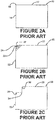
- Figure 2A shows a first prior art tread block 10 that includes a ground-engaging surface 12, a side 14 and a ninety (90) degree edge 16 between the ground engaging surface and the side.
- Figure 2B shows a second prior art tread block 18 that includes a ground-engaging surface 20, a side 22 and a chamfer 24 formed at a forty-five (45) degree angle 26 relative to the ground-engaging surface and the side.
- Figure 2C shows a third prior art tread block 28 that includes a ground-engaging surface 30, a side 32 and a chamfer 34 formed at a ninety (90) degree angle 36 relative to the ground-engaging surface and the side.
- Figure 1 shows the behavior of the first prior art tread block 10 and the second prior art tread block 18. More particularly, a tire footprint 38 shows that a leading edge 40 of the first tread block 10 digs into a road surface 44 during braking, while an area 42 of the ground-engaging surface 12 disposed behind the leading edge loses contact with the ground surface due to deformation of the block from braking forces. As described above, such behavior is often beneficial for braking on ice or snow but may sacrifice performance in wet or dry conditions due to lack of contact of the area 42 behind the leading edge 40 with the ground surface 44.
- a tire footprint 46 shows that a leading edge 48 of the second tread block 18 does not dig into the road surface 44 during braking nearly as much as the leading edge 40 of the first tread block 10. Rather, due to the chamfer 24, the ground-engaging surface area 20 of the second tread block 18 retains contact with the ground surface 44 as the tread block deforms from braking forces. As described above, the reduced tendency of the leading edge 48 to dig into the road surface 44, while performing well in wet or dry conditions, may decrease performance in winter conditions.
- the third prior art tread block 28 ( Figure 2C ) tends to perform in a manner similar to that of the second tread block 18.
- the tire 100 includes a pair of bead areas 102, each one of which is formed with a bead core 104 that is embedded in the respective bead areas.
- Each one of a pair of sidewalls 106 extends radially outward from a respective bead area 102 to a ground-contacting or ground-engaging tread 108.
- the tire 100 is reinforced by a carcass 110 that toroidally extends from one bead area 102 to the other bead area, as known to those skilled in the art.
- An innerliner 112 is formed on the inner or inside surface of the carcass 110.
- the tire 100 is mounted on the flange 114 of a wheel or rim 116, as known in the art.
- circumferentially extending grooves 118 extend about the tread 108 and define a plurality of ribs 120.
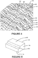
- Laterally extending grooves 122 extend in a generally lateral direction across the tread 108 and cooperate with the circumferential grooves 118 to divide the ribs 120 into tread elements or tread blocks 124.
- the laterally extending or lateral grooves 122 may extend laterally parallel to the axial direction of the tire 100, or laterally at an angle under 45 degrees relative to the axial direction of the tire.
- Each tread element 124 includes a body 126, a radially outer, ground-engaging surface 128 and a chamfer side 130.
- the chamfer side 130 may be adjacent a respective lateral groove 122 or a respective circumferential groove 118, and preferably is adjacent a lateral groove.
- the chamfer side 130 may be formed on one or more of the geometric sides of the tread element 124.
- a dual angled chamfer 132 is formed in the body 126 between the ground-engaging surface 128 and the chamfer side 130. More particularly, turning to Figures 6 and 7 , the dual angled chamfer 132 includes a first line 134 extending from a first point 136 on the chamfer side 130 to a terminus 138, and a second line 140 extending from a second point 142 on the surface 128 to the terminus.
- the terminus 138 is the point at which the first line 134 and the second line 140 meet.
- the first line 134 extends from the first point 136 to the terminus 138 at an angle 144 between 20 and 25 degrees, and preferably 22.5 degrees or 22 to 23 degrees, relative to a line 146 that extends parallel to the ground-engaging surface 128.
- the second line 140 extends from the second point 142 to the terminus 138 at an angle 148 between 20 and 25 degrees, and preferably 22.5 degrees or 22 to 23 degrees, relative to a line 150 that extends parallel to the chamfer side 130.
- the dual angled chamfer 132 extends in a radially outward direction from the first point 136 towards the surface 128 for a distance 152 that may be from 1 millimeter to 2 millimeters or 2.5 millimeters, and preferably is 2 millimeters.
- the dual angled chamfer 132 extends in an axial direction from the second point 142 towards the chamfer side 130 for a distance 154 that may be from 1 millimeter to 2 millimeters or 2.5 millimeters, and preferably is 2 millimeters.
- a length 156 of the first line 134 measured from the first point 136 to the terminus 138, is 70 percent or in a range of from 65 to 75 percent, of the axial distance 154 of the dual angled chamfer 132.
- the length 156 of the first line 134 thus is preferably 1.4 millimeters.
- a length 158 of the second line 140 measured from the second point 142 to the terminus 138, preferably is 70 percent or in a range of from 65 percent to 75 percent, of the radial distance 152 of the dual angled chamfer 132.
- the length 158 of the second line 140 thus is preferably 1.4 millimeters.
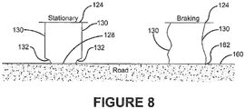
- the dual angle chamfer 132 prevents a leading edge 162 of the tread element from digging into the road surface during braking.
- the dual angle chamfer 132 thus enables the outer surface of the tread element 124 to maintain even pressure and contact on the road surface 160, thus using the whole tread element for braking.
- the dual angle chamfer 132 provides a sharper edge for the leading edge 162 than a prior art chamfer, which improves performance on snow and ice in winter conditions and helps to break water film for improved wet performance.
- the tire including a tread formed with dual angled chamfer tread elements 100 of the present invention provides features that enable improved braking performance in dry and wet conditions, while also improving performance in winter conditions.
- the tread elements 124 with a dual angled chamfer 132 reduce edge effect and tread block deformation to improve braking performance.
- the location and configuration of the dual angled chamfer 132 has a significant impact on the tread elements during braking, due to the load transfer from increased shoulder pressure.
- the dual angled chamfer 132 provides some additional initial voids in the pattern of the tread 108, which may be beneficial for traction of the tire 100 in wet conditions and winter or snow and ice conditions.
- the present invention also includes a method of forming a tire including a tread having dual angled chamfer tread elements 100, and a method of using a tire including a tread formed with dual angled chamfer tread elements.
- Each method includes steps in accordance with the description that is presented above and shown in Figures 3 through 8 .
Landscapes
- Engineering & Computer Science (AREA)
- Mechanical Engineering (AREA)
- Tires In General (AREA)
Abstract
Description
- The invention relates to pneumatic tires and to features of treads for such tires. More particularly, the invention is directed to a tire with a tread that is formed with tread elements that include a dual angled chamfer for improving braking performance in dry and wet conditions, while also improving performance in winter conditions.
- A pneumatic tire is formed with a ground-contacting tread. The tread provides the traction for the tire, and in turn, for the vehicle that the tire supports. A tread is typically formed with grooves, which are elongated void areas that extend in circumferential, lateral and/or angled manners about the tread in various configurations. The grooves define tread elements or tread blocks, which are block elements that include the ground-engaging surface. For the purpose of convenience, the terms tread element and tread block may be used interchangeably.
- In the prior art, tread blocks were formed with ninety-degree edges, which are known as squared tread blocks. During braking of the vehicle, a leading edge of a squared tread block tends to dig into the road surface, while the ground-engaging area of the tread block behind the leading edge tends to lose contact with the ground as the block deforms or buckles from braking forces. Such behavior is often beneficial for braking on ice or snow in winter conditions. However, because the full ground-engaging area of the tread block is not employed, performance of squared tread blocks and thus the tire may be sacrificed in wet or dry conditions.
- In order to improve the performance of squared tread blocks, tread blocks with a single forty-five (45) degree chamfer at the surface edges, or rounded surface edges, were developed. Such chamfered tread blocks have reduced the tendency of the leading edge of the tread block to dig into the road surface, enabling the ground-engaging area of the tread blocks behind the leading edge to retain contact with the ground as the blocks deform from braking forces. However, the chamfer reduces the edge effect of squared tread blocks, which is the tendency of the leading edge of the tread block to dig into the road surface, thereby undesirably decreasing performance of the tire in winter conditions.
- As a result, there is a need in the art for a tire with a tread that is formed with features that enable improved braking performance in wet and dry conditions, while also improving performance in winter conditions.
- The invention relates to a tire in accordance with claim 1.
- Dependent claims refer to preferred embodiments of the invention.
- According to an aspect of an exemplary embodiment of the invention, a tire includes a tread formed with tread elements that include a dual angled chamfer. The tire includes a pair of sidewalls extending radially outward to a ground-engaging tread. A plurality of circumferentially extending grooves extend about the tread and define a plurality of ribs. A plurality of laterally extending grooves cooperate with the circumferential grooves to divide the ribs into tread elements. A plurality of selected tread elements are formed with a dual angled chamfer. Each of the selected tread elements includes a body, a radially outer, ground-engaging surface, a chamfer side, and a dual angled chamfer that is formed in the body between the ground-engaging surface and the chamfer side.
- The following definitions are applicable to the present invention.
- "Axial" and "axially" mean lines or directions that are parallel to the axis of rotation of the tire.
- "Circumferential" means lines or directions extending along the perimeter of the surface of the annular tread perpendicular to the axial direction.
- "Equatorial plane" means the plane perpendicular to the axis of rotation of the tire and passing through the center of the tire tread.
- "Footprint" means the contact patch or area of contact created by the tire tread with a flat surface as the tire rotates or rolls.
- "Groove" means an elongated void area in a tread that may extend in a circumferential, lateral or angled manner about the tread in a straight, curved, or zigzag configuration.
- "Inboard side" means the side of the tire nearest the vehicle when the tire is mounted on a wheel and the wheel is mounted on the vehicle.
- "Inner" means toward the inside of the tire.
- "Lateral" and "laterally" are used to indicate axial directions across the tread of the tire.
- "Outboard side" means the side of the tire farthest away from the vehicle when the tire is mounted on a wheel and the wheel is mounted on the vehicle.
- "Outer" means radially toward the outside of the tire.
- "Radial" and "radially" are used to mean directions radially toward or away from the axis of rotation of the tire.
- "Rib" means a circumferentially extending strip of rubber on the tread which is defined by at least one circumferential groove and either a second such groove or a lateral edge, the strip being laterally undivided by full-depth grooves.
- "Tread" means a molded rubber component which includes that portion of the tire that comes into contact with the road when the tire is normally inflated and under normal load. The tread has a depth conventionally measured from the tread outer surface to the bottom of the deepest groove of the tire.
- "Tread block" or "Tread element" means a rib or a block element defined by a shape having adjacent grooves.
- The invention will be described by way of example and with reference to the accompanying drawings, in which:
-
Figure 1 is a schematic representation of the behavior of prior art tread blocks or elements; -
Figure 2A is a cross-sectional view of a portion of a first prior art tread block or element; -
Figure 2B is a cross-sectional view of a portion of a second prior art tread block or element; -
Figure 2C is a cross-sectional view of a portion of a third prior art tread block or element; -
Figure 3 is a perspective view, partially in section, of an exemplary embodiment of a tire including a tread formed with dual angled chamfer tread elements of the present invention; -
Figure 4 is an enlarged fragmentary perspective view of a portion of the tire shown inFigure 3 ; -
Figure 5 is an enlarged fragmentary perspective view of a portion of a tread element from the circled area inFigure 4 ; -
Figure 6 is an end view of the portion of the tread element shown inFigure 5 ; -
Figure 7 is an enlarged cross-sectional view of a portion of the chamfer area of the tread element shown inFigure 5 ; and -
Figure 8 is a schematic representation of the behavior of the dual angled chamfer tread elements shown inFigures 3 through 7 . - Similar numerals refer to similar parts throughout the drawings.
- By way of introduction of the tire including a tread formed with dual angled chamfer tread elements of the present invention,
Figures 1 and2A through 2C show tread elements or blocks of the prior art. -
Figure 2A shows a first priorart tread block 10 that includes a ground-engaging surface 12, aside 14 and a ninety (90)degree edge 16 between the ground engaging surface and the side.Figure 2B shows a second priorart tread block 18 that includes a ground-engaging surface 20, aside 22 and achamfer 24 formed at a forty-five (45)degree angle 26 relative to the ground-engaging surface and the side.Figure 2C shows a third priorart tread block 28 that includes a ground-engaging surface 30, aside 32 and achamfer 34 formed at a ninety (90)degree angle 36 relative to the ground-engaging surface and the side. -
Figure 1 shows the behavior of the first priorart tread block 10 and the second priorart tread block 18. More particularly, atire footprint 38 shows that a leadingedge 40 of thefirst tread block 10 digs into aroad surface 44 during braking, while anarea 42 of the ground-engaging surface 12 disposed behind the leading edge loses contact with the ground surface due to deformation of the block from braking forces. As described above, such behavior is often beneficial for braking on ice or snow but may sacrifice performance in wet or dry conditions due to lack of contact of thearea 42 behind the leadingedge 40 with theground surface 44. - A
tire footprint 46 shows that a leadingedge 48 of thesecond tread block 18 does not dig into theroad surface 44 during braking nearly as much as the leadingedge 40 of thefirst tread block 10. Rather, due to thechamfer 24, the ground-engagingsurface area 20 of thesecond tread block 18 retains contact with theground surface 44 as the tread block deforms from braking forces. As described above, the reduced tendency of the leadingedge 48 to dig into theroad surface 44, while performing well in wet or dry conditions, may decrease performance in winter conditions. The third prior art tread block 28 (Figure 2C ) tends to perform in a manner similar to that of thesecond tread block 18. - Turning now to
Figures 3 through 8 , an exemplary embodiment of atire 100 including a tread formed with dual angled chamfer tread elements of the present invention is indicated. As shown inFigure 3 , thetire 100 includes a pair ofbead areas 102, each one of which is formed with abead core 104 that is embedded in the respective bead areas. Each one of a pair ofsidewalls 106 extends radially outward from arespective bead area 102 to a ground-contacting or ground-engagingtread 108. Thetire 100 is reinforced by acarcass 110 that toroidally extends from onebead area 102 to the other bead area, as known to those skilled in the art. Aninnerliner 112 is formed on the inner or inside surface of thecarcass 110. Thetire 100 is mounted on theflange 114 of a wheel orrim 116, as known in the art. - Referring to
Figures 4 and 5 , circumferentially extendinggrooves 118 extend about thetread 108 and define a plurality ofribs 120. Laterally extendinggrooves 122 extend in a generally lateral direction across thetread 108 and cooperate with thecircumferential grooves 118 to divide theribs 120 into tread elements or tread blocks 124. The laterally extending orlateral grooves 122 may extend laterally parallel to the axial direction of thetire 100, or laterally at an angle under 45 degrees relative to the axial direction of the tire. Eachtread element 124 includes abody 126, a radially outer, ground-engagingsurface 128 and achamfer side 130. - The
chamfer side 130 may be adjacent a respectivelateral groove 122 or a respectivecircumferential groove 118, and preferably is adjacent a lateral groove. In addition, thechamfer side 130 may be formed on one or more of the geometric sides of thetread element 124. For the purpose of convenience, reference shall be made to asingle chamfer side 130 that is adjacent a respectivelateral groove 122, with the understanding that such reference may include multiple sides as well as sides adjacent a respectivecircumferential groove 118. - A dual
angled chamfer 132 is formed in thebody 126 between the ground-engagingsurface 128 and thechamfer side 130. More particularly, turning toFigures 6 and 7 , the dualangled chamfer 132 includes afirst line 134 extending from afirst point 136 on thechamfer side 130 to aterminus 138, and asecond line 140 extending from asecond point 142 on thesurface 128 to the terminus. Theterminus 138 is the point at which thefirst line 134 and thesecond line 140 meet. Thefirst line 134 extends from thefirst point 136 to theterminus 138 at anangle 144 between 20 and 25 degrees, and preferably 22.5 degrees or 22 to 23 degrees, relative to aline 146 that extends parallel to the ground-engagingsurface 128. Thesecond line 140 extends from thesecond point 142 to theterminus 138 at anangle 148 between 20 and 25 degrees, and preferably 22.5 degrees or 22 to 23 degrees, relative to aline 150 that extends parallel to thechamfer side 130. - The dual
angled chamfer 132 extends in a radially outward direction from thefirst point 136 towards thesurface 128 for adistance 152 that may be from 1 millimeter to 2 millimeters or 2.5 millimeters, and preferably is 2 millimeters. The dualangled chamfer 132 extends in an axial direction from thesecond point 142 towards thechamfer side 130 for adistance 154 that may be from 1 millimeter to 2 millimeters or 2.5 millimeters, and preferably is 2 millimeters. - Preferably, a
length 156 of thefirst line 134, measured from thefirst point 136 to theterminus 138, is 70 percent or in a range of from 65 to 75 percent, of theaxial distance 154 of the dualangled chamfer 132. When theaxial distance 154 of the dualangled chamfer 132 is 2 millimeters, thelength 156 of thefirst line 134 thus is preferably 1.4 millimeters. - In addition, a
length 158 of thesecond line 140, measured from thesecond point 142 to theterminus 138, preferably is 70 percent or in a range of from 65 percent to 75 percent, of theradial distance 152 of the dualangled chamfer 132. When theradial distance 152 of the dual angled chamfer is 2 millimeters, thelength 158 of thesecond line 140 thus is preferably 1.4 millimeters. - Turning to
Figure 8 , when thetread element 124 is in contact with aroad surface 160, thedual angle chamfer 132 prevents aleading edge 162 of the tread element from digging into the road surface during braking. Thedual angle chamfer 132 thus enables the outer surface of thetread element 124 to maintain even pressure and contact on theroad surface 160, thus using the whole tread element for braking. In addition, thedual angle chamfer 132 provides a sharper edge for theleading edge 162 than a prior art chamfer, which improves performance on snow and ice in winter conditions and helps to break water film for improved wet performance. - In this manner, the tire including a tread formed with dual angled
chamfer tread elements 100 of the present invention provides features that enable improved braking performance in dry and wet conditions, while also improving performance in winter conditions. Thetread elements 124 with a dualangled chamfer 132 reduce edge effect and tread block deformation to improve braking performance. When formed in aside 130 of thetread element 124 adjacent alateral groove 122, the location and configuration of the dualangled chamfer 132 has a significant impact on the tread elements during braking, due to the load transfer from increased shoulder pressure. In addition, the dualangled chamfer 132 provides some additional initial voids in the pattern of thetread 108, which may be beneficial for traction of thetire 100 in wet conditions and winter or snow and ice conditions. - The present invention also includes a method of forming a tire including a tread having dual angled
chamfer tread elements 100, and a method of using a tire including a tread formed with dual angled chamfer tread elements. Each method includes steps in accordance with the description that is presented above and shown inFigures 3 through 8 . - It is to be understood that the structure of the above-described tire including a tread formed with dual angled chamfer tread elements of the
present invention 100 may be altered or rearranged, or components or steps known to those skilled in the art omitted or added, without affecting the overall concept or operation of the invention.
Claims (13)
- A tire with a tread (108) formed with tread elements (124) including a dual angled chamfer (132), the tire (100) comprising:a pair of sidewalls (106) extending radially outward to a tread (108) for ground engagement;a plurality of circumferentially extending grooves (118) extending about the tread (108) and defining a plurality of ribs (120);a plurality of laterally extending grooves (122) cooperating with the circumferential grooves (118) to divide the ribs (120) into tread elements (124); anda plurality of selected tread elements (124) being formed with a dual angled chamfer (132), wherein each of the selected tread elements (124) includes a body (126), a radially outer surface (128) for ground-engagement, a chamfer side (130) and a dual angled chamfer (132) being formed in the body (126) between the radially outer surface (128) and the chamfer side (130).
- The tire of claim 1, wherein the dual angled chamfer (132) includes a first line (134) extending from a first point (136) on the chamfer side (130) to a terminus (138), and a second line (140) extending from a second point (142) on the radially outer surface (128) to the terminus (138).
- The tire of claim 2, wherein the first line (134) extends from the first point (136) to the terminus (138) at an angle in a range of from 20 to 25 degrees relative to a line that extends parallel to the radially outer surface (128).
- The tire of claim 3, wherein the first line (134) extends from the first point (136) to the terminus (138) at an angle of 22.5 degrees or in a range of from 22 to 23 degrees relative to a line that extends parallel to the radially outer surface (128).
- The tire of claim 2, wherein the second line (140) extends from the second point (142) to the terminus (138) at an angle in a range of from 20 to 25 degrees relative to a line that extends parallel to the chamfer side (130).
- The tire of claim 5, wherein the second line (140) extends from the second point (142) to the terminus (138) at an angle 22.5 degrees or in a range of from 22 to 23 degrees relative to a line that extends parallel to the chamfer side (130).
- The tire of at least one of the previous claims, wherein a length of the first line (134) is 70 percent or in a range of 65 to 75 percent of the axial distance (154) of the dual angled chamfer (132).
- The tire of at least one of the previous claims, wherein a length of the second line (140) is 70 percent or in a range of 65 to 75 percent of the radial distance (152) of the dual angled chamfer (132).
- The tire of at least one of the previous claims, wherein the chamfer side (130) is adjacent a respective lateral groove (122).
- The tire of at least one of the previous claims, wherein the chamfer side (130) is adjacent a circumferential groove (118).
- The tire of at least one of the previous claims, wherein each of the selected tread elements is formed with a plurality of dual angled chamfers (132).
- The tire of at least one of the previous claims, wherein the laterally extending grooves (122) extend laterally parallel to an axial direction of the tire (100) or within a range of +/- 10 degrees with respect to an axial direction of the tire (100).
- The tire of at least one of the previous claims, wherein the laterally extending grooves (122) extend laterally at an angle under 45 degrees with respect to an axial direction of the tire (100).
Applications Claiming Priority (1)
| Application Number | Priority Date | Filing Date | Title |
|---|---|---|---|
| US16/718,754 US11472232B2 (en) | 2019-12-18 | 2019-12-18 | Tire with tread elements including dual angled chamfer |
Publications (2)
| Publication Number | Publication Date |
|---|---|
| EP3838627A1 true EP3838627A1 (en) | 2021-06-23 |
| EP3838627B1 EP3838627B1 (en) | 2023-07-19 |
Family
ID=73854676
Family Applications (1)
| Application Number | Title | Priority Date | Filing Date |
|---|---|---|---|
| EP20214350.9A Active EP3838627B1 (en) | 2019-12-18 | 2020-12-15 | Tire with tread elements including dual angled chamfer |
Country Status (2)
| Country | Link |
|---|---|
| US (1) | US11472232B2 (en) |
| EP (1) | EP3838627B1 (en) |
Cited By (2)
| Publication number | Priority date | Publication date | Assignee | Title |
|---|---|---|---|---|
| USD1066222S1 (en) * | 2023-04-11 | 2025-03-11 | Bridgestone Corporation | Tire tread |
| USD1067170S1 (en) * | 2023-04-11 | 2025-03-18 | Bridgestone Corporation | Tire tread |
Families Citing this family (4)
| Publication number | Priority date | Publication date | Assignee | Title |
|---|---|---|---|---|
| JP1757467S (en) * | 2023-04-11 | 2023-11-15 | ||
| JP1757796S (en) * | 2023-04-11 | 2023-11-17 | ||
| JP1757795S (en) * | 2023-04-11 | 2023-11-17 | ||
| JP1757466S (en) * | 2023-04-11 | 2023-11-15 |
Citations (3)
| Publication number | Priority date | Publication date | Assignee | Title |
|---|---|---|---|---|
| EP0849101A2 (en) * | 1996-12-19 | 1998-06-24 | Sumitomo Rubber Industries Ltd. | Heavy duty radial tyre |
| EP1074405A1 (en) * | 1999-02-22 | 2001-02-07 | Bridgestone Corporation | Pneumatic tire |
| DE102010017010A1 (en) * | 2010-05-18 | 2011-11-24 | Continental Reifen Deutschland Gmbh | Tread profile for vehicle pneumatic tire, has profile block row, which is limited in both axial directions by circumferential grooves, where radial external surface is formed in cross sectional planes |
Family Cites Families (18)
| Publication number | Priority date | Publication date | Assignee | Title |
|---|---|---|---|---|
| JPH02270609A (en) | 1989-04-13 | 1990-11-05 | Yokohama Rubber Co Ltd:The | Pneumatic tire |
| JPH03132403A (en) * | 1989-10-18 | 1991-06-05 | Bridgestone Corp | Radial tire for heavy load |
| JPH03186406A (en) * | 1989-12-14 | 1991-08-14 | Yokohama Rubber Co Ltd:The | Pneumatic radial tire |
| US5456301A (en) * | 1991-07-30 | 1995-10-10 | Uniroyal Goodrich Licensing Services, Inc. | Tire tread with improved resistance to chunking |
| US5733393A (en) | 1996-01-17 | 1998-03-31 | The Goodyear Tire & Rubber Company | Tire having good diverse properties |
| US6520230B1 (en) | 2000-09-06 | 2003-02-18 | The Goodyear Tire & Rubber Company | Tire with an open tread |
| US6983777B2 (en) | 2002-10-15 | 2006-01-10 | The Goodyear Tire & Rubber Company | Tire tread with multi-planar chamfers |
| WO2004041556A1 (en) | 2002-11-06 | 2004-05-21 | Bridgestone Corporation | Pneumatic tire |
| US6968881B2 (en) | 2003-06-23 | 2005-11-29 | The Goodyear Tire & Rubber Company | Pneumatic tire including steeply slanted grooves, rib having sipes and blocks having sipes |
| US7143798B2 (en) | 2003-06-23 | 2006-12-05 | The Goodyear Tire & Rubber Company | Pneumatic tire having tread with axially adjacent block chamfer and rib chamfer |
| US9079459B2 (en) | 2007-02-07 | 2015-07-14 | Bridgestone Firestone North American Tire, Llc | Tire with tread including rib having chamfered surface |
| JP5222337B2 (en) | 2010-09-27 | 2013-06-26 | 住友ゴム工業株式会社 | Pneumatic tire |
| CN103863016B (en) * | 2012-12-12 | 2017-09-08 | 住友橡胶工业株式会社 | Pneumatic tire |
| JP5913192B2 (en) * | 2013-05-15 | 2016-04-27 | 住友ゴム工業株式会社 | Pneumatic tire |
| JP6082378B2 (en) | 2014-11-28 | 2017-02-15 | 住友ゴム工業株式会社 | Pneumatic tire |
| JP6405284B2 (en) | 2015-04-17 | 2018-10-17 | 住友ゴム工業株式会社 | Pneumatic tire |
| WO2018229578A1 (en) * | 2017-06-12 | 2018-12-20 | Pirelli Tyre S.P.A. | Tyre for vehicle wheels |
| JP6916067B2 (en) * | 2017-08-31 | 2021-08-11 | Toyo Tire株式会社 | Pneumatic tires |
-
2019
- 2019-12-18 US US16/718,754 patent/US11472232B2/en active Active
-
2020
- 2020-12-15 EP EP20214350.9A patent/EP3838627B1/en active Active
Patent Citations (3)
| Publication number | Priority date | Publication date | Assignee | Title |
|---|---|---|---|---|
| EP0849101A2 (en) * | 1996-12-19 | 1998-06-24 | Sumitomo Rubber Industries Ltd. | Heavy duty radial tyre |
| EP1074405A1 (en) * | 1999-02-22 | 2001-02-07 | Bridgestone Corporation | Pneumatic tire |
| DE102010017010A1 (en) * | 2010-05-18 | 2011-11-24 | Continental Reifen Deutschland Gmbh | Tread profile for vehicle pneumatic tire, has profile block row, which is limited in both axial directions by circumferential grooves, where radial external surface is formed in cross sectional planes |
Cited By (2)
| Publication number | Priority date | Publication date | Assignee | Title |
|---|---|---|---|---|
| USD1066222S1 (en) * | 2023-04-11 | 2025-03-11 | Bridgestone Corporation | Tire tread |
| USD1067170S1 (en) * | 2023-04-11 | 2025-03-18 | Bridgestone Corporation | Tire tread |
Also Published As
| Publication number | Publication date |
|---|---|
| US20210188010A1 (en) | 2021-06-24 |
| EP3838627B1 (en) | 2023-07-19 |
| US11472232B2 (en) | 2022-10-18 |
Similar Documents
| Publication | Publication Date | Title |
|---|---|---|
| EP3838627B1 (en) | Tire with tread elements including dual angled chamfer | |
| EP3015286B1 (en) | Pneumatic tire | |
| US4881586A (en) | All-terrain pneumatic tire | |
| US11685193B2 (en) | Tire tread for HGV trailer | |
| CN110509724B (en) | Tyre for vehicle wheels | |
| JP7187255B2 (en) | pneumatic tire | |
| EP2314466A1 (en) | Stud for a tire and tire comprising such a stud | |
| US10953697B2 (en) | Tire for sand traction | |
| CN102991280A (en) | High mileage truck tire tread | |
| EP3666551B1 (en) | Tire tread | |
| US20200262248A1 (en) | Pneumatic tyre, tyre mold and method for manufacturing pneumatic tyre using the same | |
| EP3305554B1 (en) | Pneumatic tire | |
| JPS61222806A (en) | Improvements in wheel driving car and radial-ply tire thereof | |
| US12496856B2 (en) | Pneumatic tire | |
| EP3670209B1 (en) | Tread for a pneumatic tire | |
| US20230219374A1 (en) | Tire Tread for a Heavy Vehicle with an Improved Resistance to Stresses | |
| CN110740882B (en) | Tyre for vehicle wheels | |
| JPS6143201B2 (en) | ||
| KR102262854B1 (en) | A tire comprising a tread with asymmetric groove profiles | |
| CN120916905A (en) | Pneumatic tire for vehicle | |
| EP3744535B1 (en) | Tire | |
| EP3549793B1 (en) | Tyre | |
| JP2588065B2 (en) | Pneumatic flat tire | |
| EP3970993B1 (en) | Tire tread and tire comprising a stabilizer structure | |
| EP3160774B1 (en) | Tire treads having tread elements with inclined leading sides |
Legal Events
| Date | Code | Title | Description |
|---|---|---|---|
| PUAI | Public reference made under article 153(3) epc to a published international application that has entered the european phase |
Free format text: ORIGINAL CODE: 0009012 |
|
| STAA | Information on the status of an ep patent application or granted ep patent |
Free format text: STATUS: THE APPLICATION HAS BEEN PUBLISHED |
|
| AK | Designated contracting states |
Kind code of ref document: A1 Designated state(s): AL AT BE BG CH CY CZ DE DK EE ES FI FR GB GR HR HU IE IS IT LI LT LU LV MC MK MT NL NO PL PT RO RS SE SI SK SM TR |
|
| STAA | Information on the status of an ep patent application or granted ep patent |
Free format text: STATUS: REQUEST FOR EXAMINATION WAS MADE |
|
| 17P | Request for examination filed |
Effective date: 20211223 |
|
| RBV | Designated contracting states (corrected) |
Designated state(s): AL AT BE BG CH CY CZ DE DK EE ES FI FR GB GR HR HU IE IS IT LI LT LU LV MC MK MT NL NO PL PT RO RS SE SI SK SM TR |
|
| GRAP | Despatch of communication of intention to grant a patent |
Free format text: ORIGINAL CODE: EPIDOSNIGR1 |
|
| STAA | Information on the status of an ep patent application or granted ep patent |
Free format text: STATUS: GRANT OF PATENT IS INTENDED |
|
| INTG | Intention to grant announced |
Effective date: 20230206 |
|
| GRAS | Grant fee paid |
Free format text: ORIGINAL CODE: EPIDOSNIGR3 |
|
| GRAA | (expected) grant |
Free format text: ORIGINAL CODE: 0009210 |
|
| STAA | Information on the status of an ep patent application or granted ep patent |
Free format text: STATUS: THE PATENT HAS BEEN GRANTED |
|
| AK | Designated contracting states |
Kind code of ref document: B1 Designated state(s): AL AT BE BG CH CY CZ DE DK EE ES FI FR GB GR HR HU IE IS IT LI LT LU LV MC MK MT NL NO PL PT RO RS SE SI SK SM TR |
|
| REG | Reference to a national code |
Ref country code: GB Ref legal event code: FG4D |
|
| REG | Reference to a national code |
Ref country code: CH Ref legal event code: EP |
|
| REG | Reference to a national code |
Ref country code: DE Ref legal event code: R096 Ref document number: 602020014016 Country of ref document: DE |
|
| REG | Reference to a national code |
Ref country code: IE Ref legal event code: FG4D |
|
| REG | Reference to a national code |
Ref country code: LT Ref legal event code: MG9D |
|
| REG | Reference to a national code |
Ref country code: NL Ref legal event code: MP Effective date: 20230719 |
|
| REG | Reference to a national code |
Ref country code: AT Ref legal event code: MK05 Ref document number: 1589107 Country of ref document: AT Kind code of ref document: T Effective date: 20230719 |
|
| PG25 | Lapsed in a contracting state [announced via postgrant information from national office to epo] |
Ref country code: NL Free format text: LAPSE BECAUSE OF FAILURE TO SUBMIT A TRANSLATION OF THE DESCRIPTION OR TO PAY THE FEE WITHIN THE PRESCRIBED TIME-LIMIT Effective date: 20230719 |
|
| PG25 | Lapsed in a contracting state [announced via postgrant information from national office to epo] |
Ref country code: GR Free format text: LAPSE BECAUSE OF FAILURE TO SUBMIT A TRANSLATION OF THE DESCRIPTION OR TO PAY THE FEE WITHIN THE PRESCRIBED TIME-LIMIT Effective date: 20231020 |
|
| PG25 | Lapsed in a contracting state [announced via postgrant information from national office to epo] |
Ref country code: IS Free format text: LAPSE BECAUSE OF FAILURE TO SUBMIT A TRANSLATION OF THE DESCRIPTION OR TO PAY THE FEE WITHIN THE PRESCRIBED TIME-LIMIT Effective date: 20231119 |
|
| PG25 | Lapsed in a contracting state [announced via postgrant information from national office to epo] |
Ref country code: SE Free format text: LAPSE BECAUSE OF FAILURE TO SUBMIT A TRANSLATION OF THE DESCRIPTION OR TO PAY THE FEE WITHIN THE PRESCRIBED TIME-LIMIT Effective date: 20230719 Ref country code: RS Free format text: LAPSE BECAUSE OF FAILURE TO SUBMIT A TRANSLATION OF THE DESCRIPTION OR TO PAY THE FEE WITHIN THE PRESCRIBED TIME-LIMIT Effective date: 20230719 Ref country code: PT Free format text: LAPSE BECAUSE OF FAILURE TO SUBMIT A TRANSLATION OF THE DESCRIPTION OR TO PAY THE FEE WITHIN THE PRESCRIBED TIME-LIMIT Effective date: 20231120 Ref country code: NO Free format text: LAPSE BECAUSE OF FAILURE TO SUBMIT A TRANSLATION OF THE DESCRIPTION OR TO PAY THE FEE WITHIN THE PRESCRIBED TIME-LIMIT Effective date: 20231019 Ref country code: LV Free format text: LAPSE BECAUSE OF FAILURE TO SUBMIT A TRANSLATION OF THE DESCRIPTION OR TO PAY THE FEE WITHIN THE PRESCRIBED TIME-LIMIT Effective date: 20230719 Ref country code: LT Free format text: LAPSE BECAUSE OF FAILURE TO SUBMIT A TRANSLATION OF THE DESCRIPTION OR TO PAY THE FEE WITHIN THE PRESCRIBED TIME-LIMIT Effective date: 20230719 Ref country code: IS Free format text: LAPSE BECAUSE OF FAILURE TO SUBMIT A TRANSLATION OF THE DESCRIPTION OR TO PAY THE FEE WITHIN THE PRESCRIBED TIME-LIMIT Effective date: 20231119 Ref country code: HR Free format text: LAPSE BECAUSE OF FAILURE TO SUBMIT A TRANSLATION OF THE DESCRIPTION OR TO PAY THE FEE WITHIN THE PRESCRIBED TIME-LIMIT Effective date: 20230719 Ref country code: GR Free format text: LAPSE BECAUSE OF FAILURE TO SUBMIT A TRANSLATION OF THE DESCRIPTION OR TO PAY THE FEE WITHIN THE PRESCRIBED TIME-LIMIT Effective date: 20231020 Ref country code: FI Free format text: LAPSE BECAUSE OF FAILURE TO SUBMIT A TRANSLATION OF THE DESCRIPTION OR TO PAY THE FEE WITHIN THE PRESCRIBED TIME-LIMIT Effective date: 20230719 Ref country code: AT Free format text: LAPSE BECAUSE OF FAILURE TO SUBMIT A TRANSLATION OF THE DESCRIPTION OR TO PAY THE FEE WITHIN THE PRESCRIBED TIME-LIMIT Effective date: 20230719 |
|
| PG25 | Lapsed in a contracting state [announced via postgrant information from national office to epo] |
Ref country code: PL Free format text: LAPSE BECAUSE OF FAILURE TO SUBMIT A TRANSLATION OF THE DESCRIPTION OR TO PAY THE FEE WITHIN THE PRESCRIBED TIME-LIMIT Effective date: 20230719 |
|
| REG | Reference to a national code |
Ref country code: DE Ref legal event code: R097 Ref document number: 602020014016 Country of ref document: DE |
|
| PG25 | Lapsed in a contracting state [announced via postgrant information from national office to epo] |
Ref country code: ES Free format text: LAPSE BECAUSE OF FAILURE TO SUBMIT A TRANSLATION OF THE DESCRIPTION OR TO PAY THE FEE WITHIN THE PRESCRIBED TIME-LIMIT Effective date: 20230719 |
|
| PG25 | Lapsed in a contracting state [announced via postgrant information from national office to epo] |
Ref country code: SM Free format text: LAPSE BECAUSE OF FAILURE TO SUBMIT A TRANSLATION OF THE DESCRIPTION OR TO PAY THE FEE WITHIN THE PRESCRIBED TIME-LIMIT Effective date: 20230719 Ref country code: RO Free format text: LAPSE BECAUSE OF FAILURE TO SUBMIT A TRANSLATION OF THE DESCRIPTION OR TO PAY THE FEE WITHIN THE PRESCRIBED TIME-LIMIT Effective date: 20230719 Ref country code: ES Free format text: LAPSE BECAUSE OF FAILURE TO SUBMIT A TRANSLATION OF THE DESCRIPTION OR TO PAY THE FEE WITHIN THE PRESCRIBED TIME-LIMIT Effective date: 20230719 Ref country code: EE Free format text: LAPSE BECAUSE OF FAILURE TO SUBMIT A TRANSLATION OF THE DESCRIPTION OR TO PAY THE FEE WITHIN THE PRESCRIBED TIME-LIMIT Effective date: 20230719 Ref country code: DK Free format text: LAPSE BECAUSE OF FAILURE TO SUBMIT A TRANSLATION OF THE DESCRIPTION OR TO PAY THE FEE WITHIN THE PRESCRIBED TIME-LIMIT Effective date: 20230719 Ref country code: CZ Free format text: LAPSE BECAUSE OF FAILURE TO SUBMIT A TRANSLATION OF THE DESCRIPTION OR TO PAY THE FEE WITHIN THE PRESCRIBED TIME-LIMIT Effective date: 20230719 Ref country code: SK Free format text: LAPSE BECAUSE OF FAILURE TO SUBMIT A TRANSLATION OF THE DESCRIPTION OR TO PAY THE FEE WITHIN THE PRESCRIBED TIME-LIMIT Effective date: 20230719 |
|
| PLBE | No opposition filed within time limit |
Free format text: ORIGINAL CODE: 0009261 |
|
| STAA | Information on the status of an ep patent application or granted ep patent |
Free format text: STATUS: NO OPPOSITION FILED WITHIN TIME LIMIT |
|
| 26N | No opposition filed |
Effective date: 20240422 |
|
| PG25 | Lapsed in a contracting state [announced via postgrant information from national office to epo] |
Ref country code: SI Free format text: LAPSE BECAUSE OF FAILURE TO SUBMIT A TRANSLATION OF THE DESCRIPTION OR TO PAY THE FEE WITHIN THE PRESCRIBED TIME-LIMIT Effective date: 20230719 |
|
| REG | Reference to a national code |
Ref country code: CH Ref legal event code: PL |
|
| PG25 | Lapsed in a contracting state [announced via postgrant information from national office to epo] |
Ref country code: LU Free format text: LAPSE BECAUSE OF NON-PAYMENT OF DUE FEES Effective date: 20231215 |
|
| PG25 | Lapsed in a contracting state [announced via postgrant information from national office to epo] |
Ref country code: MC Free format text: LAPSE BECAUSE OF FAILURE TO SUBMIT A TRANSLATION OF THE DESCRIPTION OR TO PAY THE FEE WITHIN THE PRESCRIBED TIME-LIMIT Effective date: 20230719 |
|
| REG | Reference to a national code |
Ref country code: BE Ref legal event code: MM Effective date: 20231231 |
|
| PG25 | Lapsed in a contracting state [announced via postgrant information from national office to epo] |
Ref country code: MC Free format text: LAPSE BECAUSE OF FAILURE TO SUBMIT A TRANSLATION OF THE DESCRIPTION OR TO PAY THE FEE WITHIN THE PRESCRIBED TIME-LIMIT Effective date: 20230719 Ref country code: LU Free format text: LAPSE BECAUSE OF NON-PAYMENT OF DUE FEES Effective date: 20231215 |
|
| REG | Reference to a national code |
Ref country code: IE Ref legal event code: MM4A |
|
| PG25 | Lapsed in a contracting state [announced via postgrant information from national office to epo] |
Ref country code: IE Free format text: LAPSE BECAUSE OF NON-PAYMENT OF DUE FEES Effective date: 20231215 |
|
| PG25 | Lapsed in a contracting state [announced via postgrant information from national office to epo] |
Ref country code: BE Free format text: LAPSE BECAUSE OF NON-PAYMENT OF DUE FEES Effective date: 20231231 |
|
| PG25 | Lapsed in a contracting state [announced via postgrant information from national office to epo] |
Ref country code: CH Free format text: LAPSE BECAUSE OF NON-PAYMENT OF DUE FEES Effective date: 20231231 |
|
| PG25 | Lapsed in a contracting state [announced via postgrant information from national office to epo] |
Ref country code: IE Free format text: LAPSE BECAUSE OF NON-PAYMENT OF DUE FEES Effective date: 20231215 Ref country code: CH Free format text: LAPSE BECAUSE OF NON-PAYMENT OF DUE FEES Effective date: 20231231 Ref country code: BE Free format text: LAPSE BECAUSE OF NON-PAYMENT OF DUE FEES Effective date: 20231231 |
|
| PG25 | Lapsed in a contracting state [announced via postgrant information from national office to epo] |
Ref country code: BG Free format text: LAPSE BECAUSE OF FAILURE TO SUBMIT A TRANSLATION OF THE DESCRIPTION OR TO PAY THE FEE WITHIN THE PRESCRIBED TIME-LIMIT Effective date: 20230719 |
|
| PG25 | Lapsed in a contracting state [announced via postgrant information from national office to epo] |
Ref country code: BG Free format text: LAPSE BECAUSE OF FAILURE TO SUBMIT A TRANSLATION OF THE DESCRIPTION OR TO PAY THE FEE WITHIN THE PRESCRIBED TIME-LIMIT Effective date: 20230719 |
|
| PG25 | Lapsed in a contracting state [announced via postgrant information from national office to epo] |
Ref country code: CY Free format text: LAPSE BECAUSE OF FAILURE TO SUBMIT A TRANSLATION OF THE DESCRIPTION OR TO PAY THE FEE WITHIN THE PRESCRIBED TIME-LIMIT; INVALID AB INITIO Effective date: 20201215 |
|
| PG25 | Lapsed in a contracting state [announced via postgrant information from national office to epo] |
Ref country code: HU Free format text: LAPSE BECAUSE OF FAILURE TO SUBMIT A TRANSLATION OF THE DESCRIPTION OR TO PAY THE FEE WITHIN THE PRESCRIBED TIME-LIMIT; INVALID AB INITIO Effective date: 20201215 |
|
| GBPC | Gb: european patent ceased through non-payment of renewal fee |
Effective date: 20241215 |
|
| PG25 | Lapsed in a contracting state [announced via postgrant information from national office to epo] |
Ref country code: GB Free format text: LAPSE BECAUSE OF NON-PAYMENT OF DUE FEES Effective date: 20241215 |
|
| PG25 | Lapsed in a contracting state [announced via postgrant information from national office to epo] |
Ref country code: TR Free format text: LAPSE BECAUSE OF FAILURE TO SUBMIT A TRANSLATION OF THE DESCRIPTION OR TO PAY THE FEE WITHIN THE PRESCRIBED TIME-LIMIT Effective date: 20230719 |
|
| PGFP | Annual fee paid to national office [announced via postgrant information from national office to epo] |
Ref country code: DE Payment date: 20251126 Year of fee payment: 6 |
|
| PGFP | Annual fee paid to national office [announced via postgrant information from national office to epo] |
Ref country code: IT Payment date: 20251119 Year of fee payment: 6 |
|
| PGFP | Annual fee paid to national office [announced via postgrant information from national office to epo] |
Ref country code: FR Payment date: 20251120 Year of fee payment: 6 |