EP3744535B1 - Tire - Google Patents
Tire Download PDFInfo
- Publication number
- EP3744535B1 EP3744535B1 EP20156136.2A EP20156136A EP3744535B1 EP 3744535 B1 EP3744535 B1 EP 3744535B1 EP 20156136 A EP20156136 A EP 20156136A EP 3744535 B1 EP3744535 B1 EP 3744535B1
- Authority
- EP
- European Patent Office
- Prior art keywords
- tire
- sipes
- tread
- rib
- range
- Prior art date
- Legal status (The legal status is an assumption and is not a legal conclusion. Google has not performed a legal analysis and makes no representation as to the accuracy of the status listed.)
- Active
Links
- 238000005457 optimization Methods 0.000 description 3
- 238000000034 method Methods 0.000 description 2
- 230000001419 dependent effect Effects 0.000 description 1
- 239000011800 void material Substances 0.000 description 1
Images


Classifications
-
- B—PERFORMING OPERATIONS; TRANSPORTING
- B60—VEHICLES IN GENERAL
- B60C—VEHICLE TYRES; TYRE INFLATION; TYRE CHANGING; CONNECTING VALVES TO INFLATABLE ELASTIC BODIES IN GENERAL; DEVICES OR ARRANGEMENTS RELATED TO TYRES
- B60C11/00—Tyre tread bands; Tread patterns; Anti-skid inserts
- B60C11/03—Tread patterns
- B60C11/0302—Tread patterns directional pattern, i.e. with main rolling direction
-
- B—PERFORMING OPERATIONS; TRANSPORTING
- B60—VEHICLES IN GENERAL
- B60C—VEHICLE TYRES; TYRE INFLATION; TYRE CHANGING; CONNECTING VALVES TO INFLATABLE ELASTIC BODIES IN GENERAL; DEVICES OR ARRANGEMENTS RELATED TO TYRES
- B60C11/00—Tyre tread bands; Tread patterns; Anti-skid inserts
- B60C11/03—Tread patterns
- B60C11/0306—Patterns comprising block rows or discontinuous ribs
- B60C11/0309—Patterns comprising block rows or discontinuous ribs further characterised by the groove cross-section
-
- B—PERFORMING OPERATIONS; TRANSPORTING
- B60—VEHICLES IN GENERAL
- B60C—VEHICLE TYRES; TYRE INFLATION; TYRE CHANGING; CONNECTING VALVES TO INFLATABLE ELASTIC BODIES IN GENERAL; DEVICES OR ARRANGEMENTS RELATED TO TYRES
- B60C11/00—Tyre tread bands; Tread patterns; Anti-skid inserts
- B60C11/03—Tread patterns
- B60C11/0327—Tread patterns characterised by special properties of the tread pattern
-
- B—PERFORMING OPERATIONS; TRANSPORTING
- B60—VEHICLES IN GENERAL
- B60C—VEHICLE TYRES; TYRE INFLATION; TYRE CHANGING; CONNECTING VALVES TO INFLATABLE ELASTIC BODIES IN GENERAL; DEVICES OR ARRANGEMENTS RELATED TO TYRES
- B60C11/00—Tyre tread bands; Tread patterns; Anti-skid inserts
- B60C11/03—Tread patterns
- B60C11/04—Tread patterns in which the raised area of the pattern consists only of continuous circumferential ribs, e.g. zig-zag
-
- B—PERFORMING OPERATIONS; TRANSPORTING
- B60—VEHICLES IN GENERAL
- B60C—VEHICLE TYRES; TYRE INFLATION; TYRE CHANGING; CONNECTING VALVES TO INFLATABLE ELASTIC BODIES IN GENERAL; DEVICES OR ARRANGEMENTS RELATED TO TYRES
- B60C11/00—Tyre tread bands; Tread patterns; Anti-skid inserts
- B60C11/03—Tread patterns
- B60C11/12—Tread patterns characterised by the use of narrow slits or incisions, e.g. sipes
- B60C11/1204—Tread patterns characterised by the use of narrow slits or incisions, e.g. sipes with special shape of the sipe
-
- B—PERFORMING OPERATIONS; TRANSPORTING
- B60—VEHICLES IN GENERAL
- B60C—VEHICLE TYRES; TYRE INFLATION; TYRE CHANGING; CONNECTING VALVES TO INFLATABLE ELASTIC BODIES IN GENERAL; DEVICES OR ARRANGEMENTS RELATED TO TYRES
- B60C11/00—Tyre tread bands; Tread patterns; Anti-skid inserts
- B60C11/03—Tread patterns
- B60C11/12—Tread patterns characterised by the use of narrow slits or incisions, e.g. sipes
- B60C11/1236—Tread patterns characterised by the use of narrow slits or incisions, e.g. sipes with special arrangements in the tread pattern
- B60C11/124—Tread patterns characterised by the use of narrow slits or incisions, e.g. sipes with special arrangements in the tread pattern inclined with regard to a plane normal to the tread surface
-
- B—PERFORMING OPERATIONS; TRANSPORTING
- B60—VEHICLES IN GENERAL
- B60C—VEHICLE TYRES; TYRE INFLATION; TYRE CHANGING; CONNECTING VALVES TO INFLATABLE ELASTIC BODIES IN GENERAL; DEVICES OR ARRANGEMENTS RELATED TO TYRES
- B60C11/00—Tyre tread bands; Tread patterns; Anti-skid inserts
- B60C11/03—Tread patterns
- B60C11/12—Tread patterns characterised by the use of narrow slits or incisions, e.g. sipes
- B60C11/1259—Depth of the sipe
-
- B—PERFORMING OPERATIONS; TRANSPORTING
- B60—VEHICLES IN GENERAL
- B60C—VEHICLE TYRES; TYRE INFLATION; TYRE CHANGING; CONNECTING VALVES TO INFLATABLE ELASTIC BODIES IN GENERAL; DEVICES OR ARRANGEMENTS RELATED TO TYRES
- B60C11/00—Tyre tread bands; Tread patterns; Anti-skid inserts
- B60C11/03—Tread patterns
- B60C11/12—Tread patterns characterised by the use of narrow slits or incisions, e.g. sipes
- B60C11/1272—Width of the sipe
- B60C11/1281—Width of the sipe different within the same sipe, i.e. enlarged width portion at sipe bottom or along its length
-
- B—PERFORMING OPERATIONS; TRANSPORTING
- B60—VEHICLES IN GENERAL
- B60C—VEHICLE TYRES; TYRE INFLATION; TYRE CHANGING; CONNECTING VALVES TO INFLATABLE ELASTIC BODIES IN GENERAL; DEVICES OR ARRANGEMENTS RELATED TO TYRES
- B60C11/00—Tyre tread bands; Tread patterns; Anti-skid inserts
- B60C11/03—Tread patterns
- B60C11/13—Tread patterns characterised by the groove cross-section, e.g. for buttressing or preventing stone-trapping
- B60C11/1376—Three dimensional block surfaces departing from the enveloping tread contour
- B60C11/1392—Three dimensional block surfaces departing from the enveloping tread contour with chamfered block edges
-
- B—PERFORMING OPERATIONS; TRANSPORTING
- B60—VEHICLES IN GENERAL
- B60C—VEHICLE TYRES; TYRE INFLATION; TYRE CHANGING; CONNECTING VALVES TO INFLATABLE ELASTIC BODIES IN GENERAL; DEVICES OR ARRANGEMENTS RELATED TO TYRES
- B60C11/00—Tyre tread bands; Tread patterns; Anti-skid inserts
- B60C11/03—Tread patterns
- B60C2011/0337—Tread patterns characterised by particular design features of the pattern
- B60C2011/0339—Grooves
- B60C2011/0358—Lateral grooves, i.e. having an angle of 45 to 90 degees to the equatorial plane
- B60C2011/0367—Lateral grooves, i.e. having an angle of 45 to 90 degees to the equatorial plane characterised by depth
-
- B—PERFORMING OPERATIONS; TRANSPORTING
- B60—VEHICLES IN GENERAL
- B60C—VEHICLE TYRES; TYRE INFLATION; TYRE CHANGING; CONNECTING VALVES TO INFLATABLE ELASTIC BODIES IN GENERAL; DEVICES OR ARRANGEMENTS RELATED TO TYRES
- B60C11/00—Tyre tread bands; Tread patterns; Anti-skid inserts
- B60C11/03—Tread patterns
- B60C2011/0337—Tread patterns characterised by particular design features of the pattern
- B60C2011/0339—Grooves
- B60C2011/0358—Lateral grooves, i.e. having an angle of 45 to 90 degees to the equatorial plane
- B60C2011/0372—Lateral grooves, i.e. having an angle of 45 to 90 degees to the equatorial plane with particular inclination angles
-
- B—PERFORMING OPERATIONS; TRANSPORTING
- B60—VEHICLES IN GENERAL
- B60C—VEHICLE TYRES; TYRE INFLATION; TYRE CHANGING; CONNECTING VALVES TO INFLATABLE ELASTIC BODIES IN GENERAL; DEVICES OR ARRANGEMENTS RELATED TO TYRES
- B60C11/00—Tyre tread bands; Tread patterns; Anti-skid inserts
- B60C11/03—Tread patterns
- B60C11/12—Tread patterns characterised by the use of narrow slits or incisions, e.g. sipes
- B60C11/1204—Tread patterns characterised by the use of narrow slits or incisions, e.g. sipes with special shape of the sipe
- B60C2011/1209—Tread patterns characterised by the use of narrow slits or incisions, e.g. sipes with special shape of the sipe straight at the tread surface
-
- B—PERFORMING OPERATIONS; TRANSPORTING
- B60—VEHICLES IN GENERAL
- B60C—VEHICLE TYRES; TYRE INFLATION; TYRE CHANGING; CONNECTING VALVES TO INFLATABLE ELASTIC BODIES IN GENERAL; DEVICES OR ARRANGEMENTS RELATED TO TYRES
- B60C11/00—Tyre tread bands; Tread patterns; Anti-skid inserts
- B60C11/03—Tread patterns
- B60C11/12—Tread patterns characterised by the use of narrow slits or incisions, e.g. sipes
- B60C11/1272—Width of the sipe
- B60C2011/1277—Width of the sipe being narrow, i.e. less than 0.3 mm
Definitions
- the present patent application is directed to a tire and, in particular, to a tire tread with narrow grooves or sipes in blocks or ribs of the tire tread.
- tread design optimization methods tend to impact wet and dry braking in opposite directions.
- Decoupling/adding cuts may generally improve wet braking distance while higher stiffness/higher contact area may improve dry braking distance.
- a method for eliminating this trade-off and improving both wet and dry braking would be desirable.
- a tread block design in accordance with the present invention helps to improve wet and dry braking distance with tilted sipes combined with a chamfer.
- WO 2010/000797 A1 discloses tread blocks comprising chamfered inclined sipes. Tread ribs are not disclosed.
- JP 2013 001325 A discloses tread elements divided by sipes having a shallow groove at the surface.
- WO 2019/027423 A1 discloses tread elements divided by sipes, which are inclined away from the main rotational direction.
- the invention relates to a tire in accordance with claim 1 or 15 respectively.
- a tire having a tread comprising a contact surface, a middle rib formed by two circumferential grooves extending along a tire circumferential direction, and at least one or two further ribs disposed axially outward from the middle rib and a respective one of the two circumferential grooves, wherein at least one of said middle rib and said at least one or two further ribs comprises a row of circumferentially extending tread elements and a plurality of sipes, wherein the sipes are inclined toward the rotational direction of the tire when moving from the contact surface radially inwardly along the sipes and wherein the tread elements have a chamfer at the respective trailing edge of the respective tread element.
- a tire tread with another aspect of the invention a tire having a tread is disclosed, the tread including a middle rib formed by two circumferential main grooves extending along a tire circumferential direction, a first shoulder rib disposed axially outward from the center rib and one of the circumferential main grooves, and a second shoulder rib disposed axially outward from the center rib and the other of the two circumferential main grooves.
- the middle rib has a plurality of sipes inclined oppositely with respect to a tire rotational direction when moving along the sipes radially outwardly toward the contact surface such that the sipes extend farther away from a rotational axis of the tire tread as the sipes extend against the tire rotational direction.
- the middle rib thereby defines a row of circumferentially extending tread elements having chamfers at trailing edges of the tread elements.
- the chamfers extend at an angle between 20 degrees and 40 degrees relative to a radial direction of the tire tread or at an angle between 25 degrees and 35 degrees relative to a radial direction of the tire tread or at an angle of 30 degrees relative to a radial direction of the tire tread.
- the sipes extend at an angle between 10 degrees and 30 degrees relative to a radial direction of the tire tread or at an angle between 17 degrees and 23 degrees relative to a radial direction of the tire tread or at an angle of 20 degrees relative to a radial direction of the tire tread.
- the middle rib has an axial width between 15.0 mm and 30.0 mm or between 17.0 mm and 26.0 mm or 21.5 mm.
- the sipes have a radial depth between 5.0 mm and 7.0 mm or between 5.5 mm and 6.5 mm or of 6.0 mm.
- the sipes have radially upper part and a radially lower part, the chamfers comprising an entire wall of one wall of the radially upper part, the radially upper part having a radial depth between 0.75 mm and 1.75 mm or between 1.00 mm and 1.50 mm or of 1.25 mm.
- the sipes have a radially upper part and a radially lower part, the radially lower part having an uniform circumferential width between 0.50 mm and 1.50 mm or between 0.75 mm and 1.25 mm or of 1.00 mm.
- Annular means formed like a ring.
- Asymmetric tread means a tread that has a tread pattern not symmetrical about the centerplane or equatorial plane EP of the tire.
- “Circumferential” and “circumferentially” mean lines or directions extending along the perimeter of the surface of the annular tire or tread parallel to the equatorial plane (EP) and perpendicular to the axial direction.
- Equatorial plane means the plane perpendicular to the tire's axis of rotation and passing through the center of its tread; or the plane containing the circumferential centerline of the tread.
- “Groove” means an elongated void area in a tread that may extend circumferentially or laterally about the tread in a straight, curved, or zigzag manner. Circumferentially and laterally extending grooves sometimes have common portions.
- the "groove width" may be the tread surface occupied by a groove or groove portion divided by the length of such groove or groove portion; thus, the groove width may be its average width over its length.
- Grooves may be of varying depths in a tire. The depth of a groove may vary around the circumference of the tread, or the depth of one groove may be constant but vary from the depth of another groove in the tire.
- narrow or wide grooves are of substantially reduced depth as compared to wide circumferential grooves, which they interconnect, they may be regarded as forming "tie bars" tending to maintain a rib-like character in the tread region involved.
- a groove is intended to have a width large enough to remain open in the tires contact patch or footprint.
- Inboard side means the side of the tire nearest the vehicle when the tire is mounted on a wheel and the wheel is mounted on the vehicle.
- Outboard side means the side of the tire farthest away from the vehicle when the tire is mounted on a wheel and the wheel is mounted on the vehicle.
- Ring and radially mean directions radially toward or away from the axis of rotation of the tire.
- “Sipe” or “incision” means relatively small slots molded into the tread elements of the tire that subdivide the tread surface and preferably improve traction; sipes are designed to close when within the contact patch or footprint, as distinguished from grooves.
- Thread means a molded rubber component which, when bonded to a tire casing, includes that portion of the tire that comes into contact with the road when the tire is normally inflated and under normal load.
- Thread element or “traction element” means a rib or a block element.
- FIG. 1 shows an example pneumatic or non-pneumatic tire tread 1 having a contact surface 3, such as a road, and a first circumferential shoulder rib 11, a second circumferential intermediate rib 12, a third circumferential center rib 13, a fourth circumferential intermediate rib 14, and a fifth circumferential shoulder rib 15, each separated axially by a circumferential groove 9.
- the tire tread 1 is preferably attached to a tire having a specified (or pre-defined) rotational direction.
- the first rib 11 has axially extending first sipes 111.
- the second rib 12 has axially extending second sipes 122.
- the third rib 13 has axially extending third sipes 133.
- the fourth rib 14 has axially extending fourth sipes 144.
- the fifth rib 15 has axially extending fifth sipes 155.
- first, second, third, fourth and fifth sipes 111, 122, 133, 144, 155 each extend axially straight and in parallel to the rotational axis of the tire 1 and thus perpendicular to the equatorial plane of the tire 1.
- axially neighboring sipes of the first, second, third, fourth and fifth sipes 111, 122, 133, 144, 155 are circumferentially offset.
- first sipes 111 and/or the fifth sipes 155 have axially outer straight portions 117, 157 axially transitioning to axially inner angled portions 119, 159, respectively.
- the axially outer straight portions 117, 157 preferably extend axially in parallel to the rotational axis of the tire 1 and thus perpendicular to the equatorial plane of the tire 1.
- the at least one or both or the axially outer straight portions 117, 157 extends radially inwards straight in a plane perpendicular to the equatorial plane of the tire 1.
- At least one or both of the axially inner angled portions 119, 159 are angled in a plane parallel to the tread surface either into the rotational direction of the tire or against the rotational direction of the tire (not shown in Fig. 1 ).
- At least one or both of the axially inner angled portions 119, 159 are angled versus a plane perpendicular to the tread surface and through the tire axis (see Figures 3 to 5 ).
- one or both the inner angled portions 119, 159 have an axial thickness or width in a range of from 15.0 mm to 30.0 mm, more preferably 17.0 mm to 26.0 mm or 21.0 mm to 23.0 mm such as 21.5 mm.
- both inner angled portions 119, 159 have the same axial thickness or width.
- At least one, two or all of the second, third and fourth ribs 122, 133, 144 have an axial thickness or width in a range of from 15.0 mm to 30.0 mm, more preferably 17.0 mm to 26.0 mm or 21.0 mm to 23.0 mm such as 21.5 mm.
- the second and fourth ribs 122, 144 and more preferably also the third rib 133 have the same axial thickness or width.
- each inner angled portion 119, 159 and each sipe 122, 133, 144 or at least one or both of the inner angled portion 119, 159 and at least one or two of the sipes 122, 133, 144 has two parts, a radially upper part 21 preferably being open to the contact surface 3 and an adjacent radially lower part 22 preferably having a dead end at its radially innermost part.
- At least one or both of the inner angled portions 119, 159 of the first and fifth ribs 11, 15, and preferably also at least one, both or all of the second sipes 122, the third sipes 133, and the fourth sipes 144 extend in the radially lower part 22 radially inward (and circumferentially) at a first angle k to a radial depth p (as measured from the contact surface 3).
- the angle k is in a range of from 10 degrees to 30 degrees and more preferably in a range of from 17 degrees to 23 degrees such as 20 degrees.
- the angle k is measured versus a plane perpendicular to the tread surface and going through the tire axis (see Figures 3 to 5 ).
- the radial depth p is preferably in a range of from 5.0 mm to 7.0 mm and more preferably in a range of from 5.5 mm to 6.5 mm such as 6.0 mm.
- One wall of the radially upper part 21 preferably extends directly radially inward (or at an angle of 0 degree) from the contact surface 3 to a depth of r (as measured from the contact surface 3).
- the depth r is preferably in a range of from 0.75 mm to 1.75 mm and more preferably in a range of from 1.00 mm to 1.50 mm such as 1.25 mm.
- both sides of the radially lower part 22 of the inner angled portions 119, 159 and the sipes 122, 133, 144 the preferably extend radially inward at the first angle k.
- the angled radially lower part 22 has a preferably constant circumferential thickness t.
- the thickness t is preferably in a range of from 0.50 mm to 1.50 mm and more preferably from 0.75 mm to 1.25 mm such as 1.00 mm.
- the other wall of the radially upper part 21 extends from the contact surface 3 radially inwardly toward the radially lower part radially outward from the radially lower part 22 at a second angle s to form a chamfer 23 at the radially outermost leading edge of one or both of the inner angled portions 119, 159 and preferably also of at least one, both or all of the sipes 122, 133, 144.
- the angle s is again measured versus a plane perpendicular to the tread surface and going through the tire axis (see Figures 3 to 5 ).
- each tread element 25 or tread block of the ribs 11, 12, 13, 14, 15 having the chamfer 23 at the trailing edge (e.g., the final edge of a tread element or block to contact a road surface, etc.) of the tread elements 25.
- a tread element 25 when looking into the circumferential direction and into the rotational direction, a tread element 25 has one part of a sipe, namely the trailing edge site of said sipe, on the leading edge site of the respective tread element 25, and one part of a circumferentially adjacent but different sipe, namely the leading edge site of said adjacent sipe, on the trailing edge site of the respective tread element 25.
- the second angle s is preferably in a range of from 20 degrees to 40 degrees, and more preferably in a range of from 25 degrees to 35 degrees such as 30 degrees.
- tread design optimization for braking tends to impact wet and dry braking in opposite directions.
- a general trend is that lower tread stiffness improves wet braking, but penalizes dry braking.
- the above described design of the tread and the sipes 111, 122, 133, 144, 155 allows an optimization of wet braking without the trade-off in dry braking.
- FIG. 4 illustrate an example of the sipes 111, 122, 133, 144, 155 of the tire tread 1 operating under wet braking conditions also showing the rotation direction of the respective tire.
Description
- The present patent application is directed to a tire and, in particular, to a tire tread with narrow grooves or sipes in blocks or ribs of the tire tread.
- Conventionally, tread design optimization methods tend to impact wet and dry braking in opposite directions. Decoupling/adding cuts may generally improve wet braking distance while higher stiffness/higher contact area may improve dry braking distance. A method for eliminating this trade-off and improving both wet and dry braking would be desirable. A tread block design in accordance with the present invention helps to improve wet and dry braking distance with tilted sipes combined with a chamfer.
-
WO 2010/000797 A1 discloses tread blocks comprising chamfered inclined sipes. Tread ribs are not disclosed. -
JP 2013 001325 A WO 2019/027423 A1 discloses tread elements divided by sipes, which are inclined away from the main rotational direction. - The invention relates to a tire in accordance with
claim - Dependent claims refer to preferred embodiments of the invention.
- In accordance with one aspect of the invention, a tire having a tread is disclosed, the tread comprising a contact surface, a middle rib formed by two circumferential grooves extending along a tire circumferential direction, and at least one or two further ribs disposed axially outward from the middle rib and a respective one of the two circumferential grooves, wherein at least one of said middle rib and said at least one or two further ribs comprises a row of circumferentially extending tread elements and a plurality of sipes, wherein the sipes are inclined toward the rotational direction of the tire when moving from the contact surface radially inwardly along the sipes and wherein the tread elements have a chamfer at the respective trailing edge of the respective tread element.
- A tire tread with another aspect of the invention, a tire having a tread is disclosed, the tread including a middle rib formed by two circumferential main grooves extending along a tire circumferential direction, a first shoulder rib disposed axially outward from the center rib and one of the circumferential main grooves, and a second shoulder rib disposed axially outward from the center rib and the other of the two circumferential main grooves. The middle rib has a plurality of sipes inclined oppositely with respect to a tire rotational direction when moving along the sipes radially outwardly toward the contact surface such that the sipes extend farther away from a rotational axis of the tire tread as the sipes extend against the tire rotational direction. The middle rib thereby defines a row of circumferentially extending tread elements having chamfers at trailing edges of the tread elements.
- According to a preferred aspect of the tire tread, the chamfers extend at an angle between 20 degrees and 40 degrees relative to a radial direction of the tire tread or at an angle between 25 degrees and 35 degrees relative to a radial direction of the tire tread or at an angle of 30 degrees relative to a radial direction of the tire tread.
- According to another preferred aspect of the tire tread, the sipes extend at an angle between 10 degrees and 30 degrees relative to a radial direction of the tire tread or at an angle between 17 degrees and 23 degrees relative to a radial direction of the tire tread or at an angle of 20 degrees relative to a radial direction of the tire tread.
- According to another preferred aspect of the tire tread, the middle rib has an axial width between 15.0 mm and 30.0 mm or between 17.0 mm and 26.0 mm or 21.5 mm.
- According to another preferred aspect of the tire tread, the sipes have a radial depth between 5.0 mm and 7.0 mm or between 5.5 mm and 6.5 mm or of 6.0 mm.
- According to another preferred aspect of the tire tread, the sipes have radially upper part and a radially lower part, the chamfers comprising an entire wall of one wall of the radially upper part, the radially upper part having a radial depth between 0.75 mm and 1.75 mm or between 1.00 mm and 1.50 mm or of 1.25 mm.
- According to another preferred aspect of the tire tread, the sipes have a radially upper part and a radially lower part, the radially lower part having an uniform circumferential width between 0.50 mm and 1.50 mm or between 0.75 mm and 1.25 mm or of 1.00 mm.
- "Annular" means formed like a ring.
- "Asymmetric tread" means a tread that has a tread pattern not symmetrical about the centerplane or equatorial plane EP of the tire.
- "Axial" and "axially" refer to lines or directions that are parallel to the axis of rotation of the tire.
- "Circumferential" and "circumferentially" mean lines or directions extending along the perimeter of the surface of the annular tire or tread parallel to the equatorial plane (EP) and perpendicular to the axial direction.
- "Equatorial plane (EP)" means the plane perpendicular to the tire's axis of rotation and passing through the center of its tread; or the plane containing the circumferential centerline of the tread.
- "Groove" means an elongated void area in a tread that may extend circumferentially or laterally about the tread in a straight, curved, or zigzag manner. Circumferentially and laterally extending grooves sometimes have common portions. The "groove width" may be the tread surface occupied by a groove or groove portion divided by the length of such groove or groove portion; thus, the groove width may be its average width over its length. Grooves may be of varying depths in a tire. The depth of a groove may vary around the circumference of the tread, or the depth of one groove may be constant but vary from the depth of another groove in the tire. If such narrow or wide grooves are of substantially reduced depth as compared to wide circumferential grooves, which they interconnect, they may be regarded as forming "tie bars" tending to maintain a rib-like character in the tread region involved. As used herein, a groove is intended to have a width large enough to remain open in the tires contact patch or footprint.
- "Inner" means toward the inside of the tire and "outer" means toward its exterior.
- "Inboard side" means the side of the tire nearest the vehicle when the tire is mounted on a wheel and the wheel is mounted on the vehicle.
- "Outboard side" means the side of the tire farthest away from the vehicle when the tire is mounted on a wheel and the wheel is mounted on the vehicle.
- "Radial" and "radially" mean directions radially toward or away from the axis of rotation of the tire.
- "Sipe" or "incision" means relatively small slots molded into the tread elements of the tire that subdivide the tread surface and preferably improve traction; sipes are designed to close when within the contact patch or footprint, as distinguished from grooves.
- "Tread" means a molded rubber component which, when bonded to a tire casing, includes that portion of the tire that comes into contact with the road when the tire is normally inflated and under normal load.
- "Tread element" or "traction element" means a rib or a block element.
- The accompanying drawings illustrate examples of the present invention and, together with a general description of the present invention given above, and the detailed description given below, serve to explain the present invention.
-
FIG. 1 is a schematic orthogonal view of a tire tread in accordance with the present invention; -
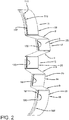
FIG. 2 is a schematic perspective view of part of the tire tread ofFIG. 1 ; -
FIG. 3 is a schematic perspective view of another part of the tire tread ofFIG. 1 ; -
FIG. 4 is a schematic side view of the tire tread ofFIG. 1 in an ideally loaded condition; and -
FIG. 5 is a schematic side detail of one of the sipes ofFIG. 4 . - This description is made for the purpose of illustrating the present invention. The scope of the present invention is best determined by reference to the appended claims. The reference numerals as depicted in the drawings are the same as those referred to in this specification. Further structural elements of the example tire and tread can for instance be found in
US-B-9,174,495 -
FIG. 1 shows an example pneumatic or non-pneumatictire tread 1 having acontact surface 3, such as a road, and a firstcircumferential shoulder rib 11, a second circumferentialintermediate rib 12, a thirdcircumferential center rib 13, a fourth circumferentialintermediate rib 14, and a fifthcircumferential shoulder rib 15, each separated axially by acircumferential groove 9. - The
tire tread 1 is preferably attached to a tire having a specified (or pre-defined) rotational direction. - The
first rib 11 has axially extendingfirst sipes 111. Thesecond rib 12 has axially extendingsecond sipes 122. Thethird rib 13 has axially extendingthird sipes 133. Thefourth rib 14 has axially extendingfourth sipes 144. Thefifth rib 15 has axially extendingfifth sipes 155. - In a preferred embodiment the first, second, third, fourth and
fifth sipes tire 1 and thus perpendicular to the equatorial plane of thetire 1. - In a preferred embodiment axially neighboring sipes of the first, second, third, fourth and
fifth sipes - In a preferred embodiment, the
first sipes 111 and/or thefifth sipes 155 have axially outerstraight portions angled portions - The axially outer
straight portions tire 1 and thus perpendicular to the equatorial plane of thetire 1. In a preferred embodiment, the at least one or both or the axially outerstraight portions tire 1. - In a preferred embodiment, at least one or both of the axially inner
angled portions Fig. 1 ). - In a preferred embodiment, at least one or both of the axially inner
angled portions Figures 3 to 5 ). - In a preferred embodiment, one or both the inner
angled portions angled portions - In a preferred embodiment, at least one, two or all of the second, third and
fourth ribs fourth ribs third rib 133 have the same axial thickness or width. - Preferably, each inner
angled portion sipe angled portion sipes upper part 21 preferably being open to thecontact surface 3 and an adjacent radiallylower part 22 preferably having a dead end at its radially innermost part. - As shown in
FIGS. 3 and5 , at least one or both of the innerangled portions fifth ribs second sipes 122, thethird sipes 133, and thefourth sipes 144 extend in the radiallylower part 22 radially inward (and circumferentially) at a first angle k to a radial depth p (as measured from the contact surface 3). - Preferably, the angle k is in a range of from 10 degrees to 30 degrees and more preferably in a range of from 17 degrees to 23 degrees such as 20 degrees. The angle k is measured versus a plane perpendicular to the tread surface and going through the tire axis (see
Figures 3 to 5 ). - The radial depth p is preferably in a range of from 5.0 mm to 7.0 mm and more preferably in a range of from 5.5 mm to 6.5 mm such as 6.0 mm.
- One wall of the radially
upper part 21 preferably extends directly radially inward (or at an angle of 0 degree) from thecontact surface 3 to a depth of r (as measured from the contact surface 3). - The depth r is preferably in a range of from 0.75 mm to 1.75 mm and more preferably in a range of from 1.00 mm to 1.50 mm such as 1.25 mm.
- From the depth r on, both sides of the radially
lower part 22 of the innerangled portions sipes - The angled radially
lower part 22 has a preferably constant circumferential thickness t. The thickness t is preferably in a range of from 0.50 mm to 1.50 mm and more preferably from 0.75 mm to 1.25 mm such as 1.00 mm. - The other wall of the radially
upper part 21 extends from thecontact surface 3 radially inwardly toward the radially lower part radially outward from the radiallylower part 22 at a second angle s to form achamfer 23 at the radially outermost leading edge of one or both of the innerangled portions sipes Figures 3 to 5 ). - Said another way, this defines a structure of each
tread element 25 or tread block of theribs chamfer 23 at the trailing edge (e.g., the final edge of a tread element or block to contact a road surface, etc.) of thetread elements 25. In this context, it is to be noted that, when looking into the circumferential direction and into the rotational direction, atread element 25 has one part of a sipe, namely the trailing edge site of said sipe, on the leading edge site of therespective tread element 25, and one part of a circumferentially adjacent but different sipe, namely the leading edge site of said adjacent sipe, on the trailing edge site of therespective tread element 25. - The second angle s is preferably in a range of from 20 degrees to 40 degrees, and more preferably in a range of from 25 degrees to 35 degrees such as 30 degrees.
- Conventionally, tread design optimization for braking tends to impact wet and dry braking in opposite directions. A general trend is that lower tread stiffness improves wet braking, but penalizes dry braking. The above described design of the tread and the
sipes -
FIG. 4 illustrate an example of thesipes tire tread 1 operating under wet braking conditions also showing the rotation direction of the respective tire.
Claims (15)
- A tire having a tread (1), the tread (1) comprising a contact surface (3), a middle rib (13) formed by two circumferential grooves (9) extending along a tire circumferential direction, and at least one or two further ribs (12, 14) disposed axially outward from the middle rib (13) and a respective one of the two circumferential grooves (9), wherein at least one of said middle rib (13) and said at least one or two further ribs (12, 14) comprises a row of circumferentially extending tread elements (25) and a plurality of sipes (122, 133, 144), wherein the sipes (122, 133, 144) are inclined toward the rotational direction of the tire when moving from the contact surface (3) radially inwardly along the sipes (122, 133, 144) and wherein the tread elements (25) have a chamfer (23) at the respective trailing edge of the respective tread element (25).
- The tire of claim 1 wherein the middle rib (13) and/or the at least or two one further ribs (12, 14) is formed by said row of circumferentially extending tread elements (25), and wherein said sipes (122, 133, 144) extend in the axial direction preferably fully across said middle rib (13) and/or said at least or one or two further ribs (12, 14) and thereby define and circumferentially delimit said tread elements (25).
- The tire of claim 1 or 2 further comprising a first shoulder rib (11) disposed axially outward from the middle rib (13) and one of the two circumferential grooves (9), and a second shoulder rib (15) disposed axially outward from the middle rib (3) and the other of the two circumferential grooves (9), at least one or both of the first and the second shoulder ribs (11, 15) comprising a row of circumferentially extending tread elements (25) and a plurality of sipes (111, 155), said sipes (111, 155) having a first axially extending preferably axially outer portion (117, 157) and a second axially extending preferably axially inner portion (119, 159), wherein the second portion (119, 159) is inclined toward the rotational direction of the tire when moving from the contact surface (3) radially inwardly along the second portion (119, 159).
- The tire of claim 3 wherein the first should rib (11) and/or the second shoulder rib (15) is formed by said row of circumferentially extending tread elements (25), and wherein said sipes (111, 155) extend in the axial direction preferably fully across said first and/or second shoulder rib (11, 15) and thereby define and circumferentially delimit said tread elements (25).
- The tire of claim 3 or 4, wherein the tread elements (25) the first shoulder rib (11) and/or the second shoulder rib (15) have a chamfer (23) at the respective trailing edge of the respective tread element (25) either axially along the full axial width of the respective tread element (25) or at least axially along the second portion (119, 159).
- The tire of claim 3, 4 or 5 wherein the first portion (117, 157) is not inclined toward the rotational direction of the tire when moving from the contact surface (3) radially inwardly along the second portion (119, 159) and preferably extends in parallel to the radial direction of the tire.
- The tire of at least one of the previous claims wherein the chamfers (23) extend at an angle (s) in a range of from 20 degrees to 40 degrees, preferably in a range of from 25 degrees to 35 degrees or at an angle of 30 degrees, relative to a radial direction of the tire.
- The tire of at least one of the previous claims wherein the sipes (122, 133, 144) in the middle rib and/or at least one or both of the further ribs (12, 14) and/or the second portions (119, 159) of at least one or both of the first and the second shoulder rib (11, 15) extend at an angle (k) in a range of from 10 degrees to 30 degrees, preferably in a range of from 17 degrees to 23 degrees or at an angle of 20 degrees, relative to a radial direction of the tire.
- The tire of at least one of the previous claims wherein the middle rib (13) has an axial width in a range of from 15.0 mm to 30.0 mm, preferably in a range of from 17.0 mm to 26.0 mm or of 21.5 mm.
- The tire of at least one of the previous claims wherein the sipes (111, 122, 133, 144, 155) have a radial depth (p) in a range of from 5.0 mm to 7.0 mm, preferably in a range of from 5.5 mm to 6.5 mm or of 6.0 mm.
- The tire of at least one of the previous claims wherein the sipes (111, 122, 133, 144, 155) have radially upper part (21) and a radially lower part (22), the chamfer (23) forming an entire wall of one wall of the radially upper part (21), the radially upper part (21) preferably a radial depth (r) in a range of from 0.75 mm to 1.75 mm, preferably in a range of from 1.0 mm to 1.5 mm or of 1.25 mm.
- The tire of at least one of the previous claims wherein the sipes (111, 122, 133, 144, 155) have a radially upper part (21) and a radially lower part (22), the radially lower part (22) having a uniform circumferential width (t) in a range of from 0.50 mm to 1.50 mm, preferably in a range of from 0.75 mm to 1.25 mm or of 1.0 mm.
- The tire of at least one of the previous claims wherein the tire has a specified or pre-defined rotational direction.
- The tire of at least one of the previous claims wherein axially neighboring sipes (111, 122, 133, 144, 155) in adjacent ribs (11, 12, 13, 14, 15) circumferentially offset against each other.
- A tire tread comprising:a middle rib (13) formed by two circumferential main grooves (9) extending along a tire circumferential direction;a first shoulder rib (11) disposed axially outward from the middle rib (13) and one of the circumferential main grooves (9); anda second shoulder rib (15) disposed axially outward from the middle rib (13) and the other of the two circumferential main grooves (9);the middle rib (13) having a plurality of sipes (133) inclined oppositely with respect to a tire rotational direction such that the sipes (133) extend farther away from a rotational axis of the tire tread (1) as the sipes (133) extend in the tire rotational direction, the middle rib thereby comprising a row of circumferentially extending tread elements (25) having chamfers (23) at trailing edges of the tread elements (25).
Priority Applications (1)
| Application Number | Priority Date | Filing Date | Title |
|---|---|---|---|
| PL20156136T PL3744535T3 (en) | 2019-02-12 | 2020-02-07 | Tire |
Applications Claiming Priority (1)
| Application Number | Priority Date | Filing Date | Title |
|---|---|---|---|
| US16/273,548 US20200254824A1 (en) | 2019-02-12 | 2019-02-12 | Tread for a tire |
Publications (2)
| Publication Number | Publication Date |
|---|---|
| EP3744535A1 EP3744535A1 (en) | 2020-12-02 |
| EP3744535B1 true EP3744535B1 (en) | 2022-01-05 |
Family
ID=69528587
Family Applications (1)
| Application Number | Title | Priority Date | Filing Date |
|---|---|---|---|
| EP20156136.2A Active EP3744535B1 (en) | 2019-02-12 | 2020-02-07 | Tire |
Country Status (4)
| Country | Link |
|---|---|
| US (1) | US20200254824A1 (en) |
| EP (1) | EP3744535B1 (en) |
| CN (1) | CN111546835A (en) |
| PL (1) | PL3744535T3 (en) |
Family Cites Families (12)
| Publication number | Priority date | Publication date | Assignee | Title |
|---|---|---|---|---|
| FR2933335B1 (en) * | 2008-07-03 | 2010-08-20 | Michelin Soc Tech | DIRECTIONAL TIRE BAND FOR TIRES WITH ADAPTED INCISIONS |
| FR2964600B1 (en) * | 2010-09-09 | 2014-08-22 | Michelin Soc Tech | TIRE TREAD FOR TIRES |
| US9174495B2 (en) | 2010-12-22 | 2015-11-03 | The Goodyear Tire & Rubber Company | Pneumatic tire with tread having sipes |
| JP5670838B2 (en) * | 2011-06-20 | 2015-02-18 | 株式会社ブリヂストン | tire |
| US20130153100A1 (en) * | 2011-12-14 | 2013-06-20 | Olivier Piffard | Tire with tread having improved wet traction |
| US9033011B1 (en) * | 2013-12-09 | 2015-05-19 | The Goodyear Tire & Rubber Company | Tire comprising a tread with asymmetric groove profiles |
| JP2015231774A (en) * | 2014-06-09 | 2015-12-24 | 株式会社ブリヂストン | tire |
| JP6441096B2 (en) * | 2015-01-29 | 2018-12-19 | 株式会社ブリヂストン | Pneumatic tire |
| JP6714985B2 (en) * | 2015-09-09 | 2020-07-01 | 株式会社ブリヂストン | tire |
| JP6627554B2 (en) * | 2016-02-15 | 2020-01-08 | 住友ゴム工業株式会社 | Pneumatic tire |
| JP6929107B2 (en) * | 2017-04-10 | 2021-09-01 | 株式会社ブリヂストン | Pneumatic radial tires for heavy loads |
| US20200369091A1 (en) * | 2017-07-31 | 2020-11-26 | Compagnie Generale Des Etablissments Michelin | Tire tread having tread blocks with inclined trailing side and sipe |
-
2019
- 2019-02-12 US US16/273,548 patent/US20200254824A1/en not_active Abandoned
-
2020
- 2020-02-07 EP EP20156136.2A patent/EP3744535B1/en active Active
- 2020-02-07 PL PL20156136T patent/PL3744535T3/en unknown
- 2020-02-12 CN CN202010088684.0A patent/CN111546835A/en active Pending
Also Published As
| Publication number | Publication date |
|---|---|
| EP3744535A1 (en) | 2020-12-02 |
| PL3744535T3 (en) | 2022-03-14 |
| US20200254824A1 (en) | 2020-08-13 |
| CN111546835A (en) | 2020-08-18 |
Similar Documents
| Publication | Publication Date | Title |
|---|---|---|
| EP3095623B1 (en) | Pneumatic tire | |
| US5407005A (en) | Tread for a tire | |
| US10513151B2 (en) | Pneumatic tire | |
| US11685193B2 (en) | Tire tread for HGV trailer | |
| EP1676728B1 (en) | Siped tire tread | |
| US10894445B2 (en) | Pneumatic tire | |
| US10814678B2 (en) | Tire | |
| EP3393827B1 (en) | Tire having exposed three dimensional sipe patterns | |
| JP7187255B2 (en) | pneumatic tire | |
| CN109968917B (en) | Tyre for vehicle wheels | |
| CN107667017A (en) | Tire tread | |
| KR102262854B1 (en) | A tire comprising a tread with asymmetric groove profiles | |
| US11383559B2 (en) | Pneumatic tire | |
| EP3744535B1 (en) | Tire | |
| EP0135467B1 (en) | Pneumatic tire | |
| EP3666551B1 (en) | Tire tread | |
| US20190054770A1 (en) | Off the road tire | |
| EP3670209B1 (en) | Tread for a pneumatic tire | |
| US11135877B2 (en) | Tire | |
| EP3970993B1 (en) | Tire tread and tire comprising a stabilizer structure | |
| EP4091841B1 (en) | Tire with a tread having sipes | |
| EP3970994A1 (en) | Tire tread and tire with such a tread | |
| US10814675B2 (en) | Tire | |
| US11904637B2 (en) | Tire | |
| CN113905905B (en) | Pneumatic tire |
Legal Events
| Date | Code | Title | Description |
|---|---|---|---|
| PUAI | Public reference made under article 153(3) epc to a published international application that has entered the european phase |
Free format text: ORIGINAL CODE: 0009012 |
|
| STAA | Information on the status of an ep patent application or granted ep patent |
Free format text: STATUS: THE APPLICATION HAS BEEN PUBLISHED |
|
| AK | Designated contracting states |
Kind code of ref document: A1 Designated state(s): AL AT BE BG CH CY CZ DE DK EE ES FI FR GB GR HR HU IE IS IT LI LT LU LV MC MK MT NL NO PL PT RO RS SE SI SK SM TR |
|
| AX | Request for extension of the european patent |
Extension state: BA ME |
|
| STAA | Information on the status of an ep patent application or granted ep patent |
Free format text: STATUS: REQUEST FOR EXAMINATION WAS MADE |
|
| 17P | Request for examination filed |
Effective date: 20210602 |
|
| RBV | Designated contracting states (corrected) |
Designated state(s): AL AT BE BG CH CY CZ DE DK EE ES FI FR GB GR HR HU IE IS IT LI LT LU LV MC MK MT NL NO PL PT RO RS SE SI SK SM TR |
|
| GRAP | Despatch of communication of intention to grant a patent |
Free format text: ORIGINAL CODE: EPIDOSNIGR1 |
|
| STAA | Information on the status of an ep patent application or granted ep patent |
Free format text: STATUS: GRANT OF PATENT IS INTENDED |
|
| RIC1 | Information provided on ipc code assigned before grant |
Ipc: B60C 11/13 20060101ALN20210722BHEP Ipc: B60C 11/12 20060101ALI20210722BHEP Ipc: B60C 11/03 20060101AFI20210722BHEP |
|
| INTG | Intention to grant announced |
Effective date: 20210824 |
|
| GRAS | Grant fee paid |
Free format text: ORIGINAL CODE: EPIDOSNIGR3 |
|
| GRAA | (expected) grant |
Free format text: ORIGINAL CODE: 0009210 |
|
| STAA | Information on the status of an ep patent application or granted ep patent |
Free format text: STATUS: THE PATENT HAS BEEN GRANTED |
|
| AK | Designated contracting states |
Kind code of ref document: B1 Designated state(s): AL AT BE BG CH CY CZ DE DK EE ES FI FR GB GR HR HU IE IS IT LI LT LU LV MC MK MT NL NO PL PT RO RS SE SI SK SM TR |
|
| REG | Reference to a national code |
Ref country code: GB Ref legal event code: FG4D |
|
| REG | Reference to a national code |
Ref country code: CH Ref legal event code: EP |
|
| REG | Reference to a national code |
Ref country code: AT Ref legal event code: REF Ref document number: 1460205 Country of ref document: AT Kind code of ref document: T Effective date: 20220115 |
|
| REG | Reference to a national code |
Ref country code: DE Ref legal event code: R096 Ref document number: 602020001480 Country of ref document: DE |
|
| REG | Reference to a national code |
Ref country code: IE Ref legal event code: FG4D |
|
| REG | Reference to a national code |
Ref country code: LT Ref legal event code: MG9D |
|
| REG | Reference to a national code |
Ref country code: NL Ref legal event code: MP Effective date: 20220105 |
|
| PGFP | Annual fee paid to national office [announced via postgrant information from national office to epo] |
Ref country code: TR Payment date: 20220322 Year of fee payment: 3 |
|
| REG | Reference to a national code |
Ref country code: AT Ref legal event code: MK05 Ref document number: 1460205 Country of ref document: AT Kind code of ref document: T Effective date: 20220105 |
|
| PG25 | Lapsed in a contracting state [announced via postgrant information from national office to epo] |
Ref country code: NL Free format text: LAPSE BECAUSE OF FAILURE TO SUBMIT A TRANSLATION OF THE DESCRIPTION OR TO PAY THE FEE WITHIN THE PRESCRIBED TIME-LIMIT Effective date: 20220105 |
|
| PG25 | Lapsed in a contracting state [announced via postgrant information from national office to epo] |
Ref country code: SE Free format text: LAPSE BECAUSE OF FAILURE TO SUBMIT A TRANSLATION OF THE DESCRIPTION OR TO PAY THE FEE WITHIN THE PRESCRIBED TIME-LIMIT Effective date: 20220105 Ref country code: RS Free format text: LAPSE BECAUSE OF FAILURE TO SUBMIT A TRANSLATION OF THE DESCRIPTION OR TO PAY THE FEE WITHIN THE PRESCRIBED TIME-LIMIT Effective date: 20220105 Ref country code: PT Free format text: LAPSE BECAUSE OF FAILURE TO SUBMIT A TRANSLATION OF THE DESCRIPTION OR TO PAY THE FEE WITHIN THE PRESCRIBED TIME-LIMIT Effective date: 20220505 Ref country code: NO Free format text: LAPSE BECAUSE OF FAILURE TO SUBMIT A TRANSLATION OF THE DESCRIPTION OR TO PAY THE FEE WITHIN THE PRESCRIBED TIME-LIMIT Effective date: 20220405 Ref country code: LT Free format text: LAPSE BECAUSE OF FAILURE TO SUBMIT A TRANSLATION OF THE DESCRIPTION OR TO PAY THE FEE WITHIN THE PRESCRIBED TIME-LIMIT Effective date: 20220105 Ref country code: HR Free format text: LAPSE BECAUSE OF FAILURE TO SUBMIT A TRANSLATION OF THE DESCRIPTION OR TO PAY THE FEE WITHIN THE PRESCRIBED TIME-LIMIT Effective date: 20220105 Ref country code: ES Free format text: LAPSE BECAUSE OF FAILURE TO SUBMIT A TRANSLATION OF THE DESCRIPTION OR TO PAY THE FEE WITHIN THE PRESCRIBED TIME-LIMIT Effective date: 20220105 Ref country code: BG Free format text: LAPSE BECAUSE OF FAILURE TO SUBMIT A TRANSLATION OF THE DESCRIPTION OR TO PAY THE FEE WITHIN THE PRESCRIBED TIME-LIMIT Effective date: 20220405 |
|
| PG25 | Lapsed in a contracting state [announced via postgrant information from national office to epo] |
Ref country code: LV Free format text: LAPSE BECAUSE OF FAILURE TO SUBMIT A TRANSLATION OF THE DESCRIPTION OR TO PAY THE FEE WITHIN THE PRESCRIBED TIME-LIMIT Effective date: 20220105 Ref country code: GR Free format text: LAPSE BECAUSE OF FAILURE TO SUBMIT A TRANSLATION OF THE DESCRIPTION OR TO PAY THE FEE WITHIN THE PRESCRIBED TIME-LIMIT Effective date: 20220406 Ref country code: FI Free format text: LAPSE BECAUSE OF FAILURE TO SUBMIT A TRANSLATION OF THE DESCRIPTION OR TO PAY THE FEE WITHIN THE PRESCRIBED TIME-LIMIT Effective date: 20220105 Ref country code: AT Free format text: LAPSE BECAUSE OF FAILURE TO SUBMIT A TRANSLATION OF THE DESCRIPTION OR TO PAY THE FEE WITHIN THE PRESCRIBED TIME-LIMIT Effective date: 20220105 |
|
| PGFP | Annual fee paid to national office [announced via postgrant information from national office to epo] |
Ref country code: PL Payment date: 20220207 Year of fee payment: 3 |
|
| PG25 | Lapsed in a contracting state [announced via postgrant information from national office to epo] |
Ref country code: IS Free format text: LAPSE BECAUSE OF FAILURE TO SUBMIT A TRANSLATION OF THE DESCRIPTION OR TO PAY THE FEE WITHIN THE PRESCRIBED TIME-LIMIT Effective date: 20220505 |
|
| REG | Reference to a national code |
Ref country code: DE Ref legal event code: R097 Ref document number: 602020001480 Country of ref document: DE |
|
| REG | Reference to a national code |
Ref country code: BE Ref legal event code: MM Effective date: 20220228 |
|
| PG25 | Lapsed in a contracting state [announced via postgrant information from national office to epo] |
Ref country code: SM Free format text: LAPSE BECAUSE OF FAILURE TO SUBMIT A TRANSLATION OF THE DESCRIPTION OR TO PAY THE FEE WITHIN THE PRESCRIBED TIME-LIMIT Effective date: 20220105 Ref country code: SK Free format text: LAPSE BECAUSE OF FAILURE TO SUBMIT A TRANSLATION OF THE DESCRIPTION OR TO PAY THE FEE WITHIN THE PRESCRIBED TIME-LIMIT Effective date: 20220105 Ref country code: RO Free format text: LAPSE BECAUSE OF FAILURE TO SUBMIT A TRANSLATION OF THE DESCRIPTION OR TO PAY THE FEE WITHIN THE PRESCRIBED TIME-LIMIT Effective date: 20220105 Ref country code: MC Free format text: LAPSE BECAUSE OF FAILURE TO SUBMIT A TRANSLATION OF THE DESCRIPTION OR TO PAY THE FEE WITHIN THE PRESCRIBED TIME-LIMIT Effective date: 20220105 Ref country code: LU Free format text: LAPSE BECAUSE OF NON-PAYMENT OF DUE FEES Effective date: 20220207 Ref country code: EE Free format text: LAPSE BECAUSE OF FAILURE TO SUBMIT A TRANSLATION OF THE DESCRIPTION OR TO PAY THE FEE WITHIN THE PRESCRIBED TIME-LIMIT Effective date: 20220105 Ref country code: DK Free format text: LAPSE BECAUSE OF FAILURE TO SUBMIT A TRANSLATION OF THE DESCRIPTION OR TO PAY THE FEE WITHIN THE PRESCRIBED TIME-LIMIT Effective date: 20220105 Ref country code: CZ Free format text: LAPSE BECAUSE OF FAILURE TO SUBMIT A TRANSLATION OF THE DESCRIPTION OR TO PAY THE FEE WITHIN THE PRESCRIBED TIME-LIMIT Effective date: 20220105 |
|
| PLBE | No opposition filed within time limit |
Free format text: ORIGINAL CODE: 0009261 |
|
| STAA | Information on the status of an ep patent application or granted ep patent |
Free format text: STATUS: NO OPPOSITION FILED WITHIN TIME LIMIT |
|
| PG25 | Lapsed in a contracting state [announced via postgrant information from national office to epo] |
Ref country code: AL Free format text: LAPSE BECAUSE OF FAILURE TO SUBMIT A TRANSLATION OF THE DESCRIPTION OR TO PAY THE FEE WITHIN THE PRESCRIBED TIME-LIMIT Effective date: 20220105 |
|
| 26N | No opposition filed |
Effective date: 20221006 |
|
| PG25 | Lapsed in a contracting state [announced via postgrant information from national office to epo] |
Ref country code: IE Free format text: LAPSE BECAUSE OF NON-PAYMENT OF DUE FEES Effective date: 20220207 |
|
| PG25 | Lapsed in a contracting state [announced via postgrant information from national office to epo] |
Ref country code: SI Free format text: LAPSE BECAUSE OF FAILURE TO SUBMIT A TRANSLATION OF THE DESCRIPTION OR TO PAY THE FEE WITHIN THE PRESCRIBED TIME-LIMIT Effective date: 20220105 Ref country code: BE Free format text: LAPSE BECAUSE OF NON-PAYMENT OF DUE FEES Effective date: 20220228 |
|
| PGFP | Annual fee paid to national office [announced via postgrant information from national office to epo] |
Ref country code: IT Payment date: 20230228 Year of fee payment: 4 Ref country code: DE Payment date: 20221213 Year of fee payment: 4 |
|
| REG | Reference to a national code |
Ref country code: CH Ref legal event code: PL |
|
| PG25 | Lapsed in a contracting state [announced via postgrant information from national office to epo] |
Ref country code: LI Free format text: LAPSE BECAUSE OF NON-PAYMENT OF DUE FEES Effective date: 20230228 Ref country code: CH Free format text: LAPSE BECAUSE OF NON-PAYMENT OF DUE FEES Effective date: 20230228 |
|
| PGFP | Annual fee paid to national office [announced via postgrant information from national office to epo] |
Ref country code: FR Payment date: 20231212 Year of fee payment: 5 |