EP3838606A1 - Printing device - Google Patents
Printing device Download PDFInfo
- Publication number
- EP3838606A1 EP3838606A1 EP20206646.0A EP20206646A EP3838606A1 EP 3838606 A1 EP3838606 A1 EP 3838606A1 EP 20206646 A EP20206646 A EP 20206646A EP 3838606 A1 EP3838606 A1 EP 3838606A1
- Authority
- EP
- European Patent Office
- Prior art keywords
- control
- axis
- encoder
- count value
- pulse signal
- Prior art date
- Legal status (The legal status is an assumption and is not a legal conclusion. Google has not performed a legal analysis and makes no representation as to the accuracy of the status listed.)
- Granted
Links
- 230000002159 abnormal effect Effects 0.000 claims abstract description 32
- 230000005856 abnormality Effects 0.000 claims description 31
- 238000010586 diagram Methods 0.000 description 23
- 230000006870 function Effects 0.000 description 16
- 238000012545 processing Methods 0.000 description 8
- 238000004891 communication Methods 0.000 description 7
- 230000007704 transition Effects 0.000 description 7
- 239000000470 constituent Substances 0.000 description 6
- 230000000694 effects Effects 0.000 description 6
- 238000006243 chemical reaction Methods 0.000 description 4
- 238000001514 detection method Methods 0.000 description 4
- 238000000034 method Methods 0.000 description 3
- 230000003247 decreasing effect Effects 0.000 description 1
- 238000012423 maintenance Methods 0.000 description 1
- 239000000463 material Substances 0.000 description 1
- 238000012986 modification Methods 0.000 description 1
- 230000004048 modification Effects 0.000 description 1
- 239000011347 resin Substances 0.000 description 1
- 229920005989 resin Polymers 0.000 description 1
Images


Classifications
-
- B—PERFORMING OPERATIONS; TRANSPORTING
- B41—PRINTING; LINING MACHINES; TYPEWRITERS; STAMPS
- B41J—TYPEWRITERS; SELECTIVE PRINTING MECHANISMS, i.e. MECHANISMS PRINTING OTHERWISE THAN FROM A FORME; CORRECTION OF TYPOGRAPHICAL ERRORS
- B41J19/00—Character- or line-spacing mechanisms
- B41J19/18—Character-spacing or back-spacing mechanisms; Carriage return or release devices therefor
- B41J19/20—Positive-feed character-spacing mechanisms
- B41J19/202—Drive control means for carriage movement
- B41J19/205—Position or speed detectors therefor
- B41J19/207—Encoding along a bar
-
- B—PERFORMING OPERATIONS; TRANSPORTING
- B41—PRINTING; LINING MACHINES; TYPEWRITERS; STAMPS
- B41J—TYPEWRITERS; SELECTIVE PRINTING MECHANISMS, i.e. MECHANISMS PRINTING OTHERWISE THAN FROM A FORME; CORRECTION OF TYPOGRAPHICAL ERRORS
- B41J2/00—Typewriters or selective printing mechanisms characterised by the printing or marking process for which they are designed
- B41J2/005—Typewriters or selective printing mechanisms characterised by the printing or marking process for which they are designed characterised by bringing liquid or particles selectively into contact with a printing material
- B41J2/01—Ink jet
- B41J2/015—Ink jet characterised by the jet generation process
- B41J2/04—Ink jet characterised by the jet generation process generating single droplets or particles on demand
- B41J2/045—Ink jet characterised by the jet generation process generating single droplets or particles on demand by pressure, e.g. electromechanical transducers
- B41J2/04501—Control methods or devices therefor, e.g. driver circuits, control circuits
- B41J2/0451—Control methods or devices therefor, e.g. driver circuits, control circuits for detecting failure, e.g. clogging, malfunctioning actuator
-
- B—PERFORMING OPERATIONS; TRANSPORTING
- B41—PRINTING; LINING MACHINES; TYPEWRITERS; STAMPS
- B41J—TYPEWRITERS; SELECTIVE PRINTING MECHANISMS, i.e. MECHANISMS PRINTING OTHERWISE THAN FROM A FORME; CORRECTION OF TYPOGRAPHICAL ERRORS
- B41J19/00—Character- or line-spacing mechanisms
- B41J19/18—Character-spacing or back-spacing mechanisms; Carriage return or release devices therefor
- B41J19/20—Positive-feed character-spacing mechanisms
- B41J19/202—Drive control means for carriage movement
-
- B—PERFORMING OPERATIONS; TRANSPORTING
- B41—PRINTING; LINING MACHINES; TYPEWRITERS; STAMPS
- B41J—TYPEWRITERS; SELECTIVE PRINTING MECHANISMS, i.e. MECHANISMS PRINTING OTHERWISE THAN FROM A FORME; CORRECTION OF TYPOGRAPHICAL ERRORS
- B41J2/00—Typewriters or selective printing mechanisms characterised by the printing or marking process for which they are designed
- B41J2/005—Typewriters or selective printing mechanisms characterised by the printing or marking process for which they are designed characterised by bringing liquid or particles selectively into contact with a printing material
- B41J2/01—Ink jet
- B41J2/015—Ink jet characterised by the jet generation process
- B41J2/04—Ink jet characterised by the jet generation process generating single droplets or particles on demand
- B41J2/045—Ink jet characterised by the jet generation process generating single droplets or particles on demand by pressure, e.g. electromechanical transducers
- B41J2/04501—Control methods or devices therefor, e.g. driver circuits, control circuits
- B41J2/04586—Control methods or devices therefor, e.g. driver circuits, control circuits controlling heads of a type not covered by groups B41J2/04575 - B41J2/04585, or of an undefined type
-
- B—PERFORMING OPERATIONS; TRANSPORTING
- B41—PRINTING; LINING MACHINES; TYPEWRITERS; STAMPS
- B41J—TYPEWRITERS; SELECTIVE PRINTING MECHANISMS, i.e. MECHANISMS PRINTING OTHERWISE THAN FROM A FORME; CORRECTION OF TYPOGRAPHICAL ERRORS
- B41J3/00—Typewriters or selective printing or marking mechanisms characterised by the purpose for which they are constructed
- B41J3/407—Typewriters or selective printing or marking mechanisms characterised by the purpose for which they are constructed for marking on special material
Definitions
- the invention relates to a printing device for performing printing on a recording medium.
- a printing device for performing printing on a recording medium by an inkjet method has been known (for example, see patent literature 1).
- This type of printing device includes a head part that ejects ink toward the recording medium, a driving mechanism that causes the head part to move with respect to the recording medium in a main scanning direction and in a sub-scanning direction substantially orthogonal to the main scanning direction, an encoder that outputs an encoder signal corresponding to the position of the head part in the main scanning direction and the sub-scanning direction, and a control part that performs feedback control which drives the driving mechanism based on the encoder signal from the encoder.
- the printing device described above further includes an abnormality detection part that detects whether the encoder signal is normally output from the encoder during printing operation.
- Patent literature 1 Japanese Patent Application Laid-open No. 2003-145877
- the control part may further continue to drive the driving mechanism because there is no feedback of the encoder signal from the encoder.
- the driving of the driving mechanism by the control part may become uncontrollable before an abnormality is detected by the abnormality detection.
- the invention provides a printing device that can determine in advance whether or not there is an abnormality in an encoder before a second control performed by a control part.
- the control part shifts from the first control to the second control when the determination
- the control part shifts from the first control to the second control, and when the determination part determines that the encoder is abnormal in the first control, the control part does not shift from the first control to the second control.
- the encoder may output a first pulse signal and a second pulse signal which have a predetermined phase difference, and the counter may count the count value based on the rise and fall of the first pulse signal and the rise and fall of the second pulse signal.
- the output of the encoder has a plurality of phases (first pulse signal and second pulse signal), it is possible to determine whether or not there is an abnormality in the encoder for all the phases.
- the determination part may determine that the encoder is normal when a count value equal to or greater than 4 is counted, and may determine that the encoder is abnormal when a count value less than 4 is counted.
- the output of the encoder has a plurality of phases, it is possible to precisely determine whether or not there is an abnormality in the encoder for all the phases.
- control part may drive the driving source by applying a constant voltage to the driving source for the first time regardless of the count value from the counter.
- control part does not perform a feedback control which drives the driving source based on the count value from the counter in the first control.
- control part in the first control, may drive the driving source so as to cause the head part to move by 1 mm or less by applying the constant voltage to the driving source for the first time.
- the head part in the first control, it is possible to cause the head part to move by 1 mm or less as a minimum distance necessary for detecting whether or not there is an abnormality in the encoder.
- the determination part may detect whether or not there is an abnormality in the encoder over the first time in which the control part applies the voltage to the driving source, and a third time in which the control part does not apply the voltage to the driving source after the elapse of the first time.
- the determination part detects whether or not there is an abnormality in the encoder over the first time in which the head part moves due to a driving force from the driving source and the third time in which the head part moves due to inertia. Therefore, even when the first time is set to be relatively short (for example, about several tens of milliseconds), it is possible to sufficiently secure a moving distance of the head part for detecting whether or not there is an abnormality in the encoder.
- the determination part may not determine that the encoder is abnormal when the counter counts to a count value less than the predetermined number, and while the control part continues to controls the driving source so as to cause the head part to move in a second direction opposite to the first direction based on the determination result of the determination part, the determination part may determine that the encoder is abnormal when the counter counts to a count value less than the predetermined number.
- the counter when the counter counts to a count value less than the predetermined number, it is not possible to determine whether it is a) a case in which the encoder is normal, but for example, the head part contacts with a housing of the printing device or the like and cannot physically move, or b) a case in which the encoder is abnormal. Therefore, in this case, by determining whether or not there is an abnormality in the encoder after reversing the moving direction of the head part from the first direction to the second direction, it is possible to prevent the determination part from erroneously determining the abnormality of the encoder in the former case described above.
- the printing device of one aspect of the invention it is possible to determine in advance whether or not there is an abnormality in the encoder before the second control performed by the control part.
- FIG. 1 is a perspective view showing an appearance of the printing device 2 according to Embodiment 1.
- FIG. 2 is a perspective view showing a printing unit 6 of the printing device 2 according to Embodiment 1.
- FIG. 3 is a perspective view showing the printing unit 6 of the printing device 2 according to Embodiment 1 with a head part 20 and an X-axis driving mechanism 22a omitted.
- the width direction (left-right direction) of the printing device 2 is described as an X-axis direction
- the depth direction (front-back direction) of the printing device 2 is described as a Y-axis direction
- the height direction of the printing device 2 is described as a Z-axis direction.
- a part of a housing 4 is cut away.
- the printing device 2 includes the housing 4 and the printing unit 6 arranged inside the housing 4.
- the printing device 2 refers to a nail printer for performing printing for manicure use of color or pattern on a nail 10 of a finger 8 of a user's hand (an example of a recording medium).
- the printing device 2 can wirelessly communicate with an external terminal (not shown) such as a smartphone or a tablet terminal.
- an external terminal such as a smartphone or a tablet terminal.
- the user can operate the printing device 2 by using an application installed in the external terminal as an interface.
- the housing 4 is made of resin for example, and is formed into a box shape.
- a power switch 12 for turning on/off the power of the printing device 2 is arranged on a top surface 4a of the housing 4.
- an opening 14 for inserting the finger 8 of the user is formed on a front surface 4b of the housing 4.
- a finger holder 16 for placing the finger 8 of the user is arranged on the lower side of the opening 14 (minus side of Z axis).
- a pressing cover 18 for pressing the finger 8 of the user from above is arranged on the upper side of the opening 14 (plus side of Z-axis).
- the finger holder 16 is movable in the vertical direction (Z-axis direction) with respect to the pressing cover 18, and is urged by a spring (not shown) in a direction approaching the pressing cover 18.
- the user inserts the finger 8 into the opening 14 (see FIG. 1 ) of the housing 4 while the finger 8 is extended straightly with the nail 10 of the finger 8 facing upward, and places the pulp side of the finger 8 on the finger holder 16.
- a part of the finger 8 including the nail 10 (for example, a part of the finger 8 from tip to vicinity of the first joint) is arranged inside the housing 4.
- the finger holder 16 is urged in the direction approaching the pressing cover 18, and thereby for example the vicinity of the first joint of the finger 8 is clamped from above and below by the finger holder 16 and the pressing cover 18.
- the printing unit 6 is a unit for performing printing for manicure use on the nail 10 of the finger 8 arranged inside the housing 4.
- the printing method of the printing unit 6 is an inkjet method in which mist-like ink is sprayed on the nail 10 of the finger 8 to thereby perform printing.
- the printing unit 6 has a head part 20 and a driving mechanism 22.
- the head part 20 has a carriage 24 and an ink tank 26 mounted on the carriage 24.
- the ink tank 26 is filled with four types of ink inside, for example, CMYK (C: cyan, M: magenta, Y: yellow, K: black).
- CMYK C: cyan, M: magenta, Y: yellow, K: black.
- a nozzle surface (not shown) from which the ink supplied from the ink tank 26 is ejected downward toward the nail 10 of the finger 8 is formed on the lower surface of the carriage 24.
- the driving mechanism 22 is a mechanism for causing the head part 20 to two-dimensionally move in a main scanning direction (X-axis direction) and a sub-scanning direction (Y-axis direction) substantially orthogonal to the main scanning direction (an example of a predetermined direction). As shown in FIG. 2 and FIG. 3 , the driving mechanism 22 has an X-axis driving mechanism 22a for causing the head part 20 to move in the main scanning direction with respect to the nail 10 of the finger 8, and a Y-axis driving mechanism 22b for causing the head part 20 to move in the sub-scanning direction with respect to the nail 10 of the finger 8.
- the X-axis driving mechanism 22a has a moving table 28, an X-axis guide shaft 30, an X-axis motor 32, and a timing belt 34.
- the X-axis guide shaft 30 is supported by the moving table 28 arranged inside the housing 4, and extends into an elongated shape in the X-axis direction.
- the head part 20 is movably supported on the X-axis guide shaft 30.
- the X-axis motor 32 is configured by, for example, a servo motor, and is supported by the lower surface of the moving table 28.
- a driving force of the X-axis motor 32 is transmitted to the head part 20 via the timing belt 34. Thereby, the head part 20 moves in the X-axis direction along the X-axis guide shaft 30 with respect to the moving table 28.
- the Y-axis driving mechanism 22b has the moving table 28 (see FIG. 2 ), a bearing member 36, a Y-axis guide shaft 38, a Y-axis motor 40 (an example of a driving source), a worm gear 42, a worm wheel 44 and a driving conversion mechanism 46.
- the Y-axis guide shaft 38 is supported by a base frame 48 arranged inside the housing 4, and extends into an elongated shape in the Y-axis direction.
- the bearing member 36 fixed to the lower surface of the moving table 28 is movably supported on the Y-axis guide shaft 38. That is, the moving table 28 is movably supported by the Y-axis guide shaft 38 via the bearing member 36.
- the Y-axis motor 40 is configured by, for example, a servo motor, and is supported by the base frame 48.
- the worm gear 42 is rotatably supported by a driving shaft of the Y-axis motor 40.
- the worm wheel 44 is rotatably supported by the base frame 48 and meshes with the worm gear 42.
- the driving conversion mechanism 46 is a mechanism for converting rotation of the worm wheel 44 into linear movement of the head part 20 in the Y-axis direction.
- the driving conversion mechanism 46 has a pinion gear 50 formed on the worm wheel 44 and a rack gear 52 formed on the bearing member 36. The pinion gear 50 and the rack gear 52 mesh with each other.
- a driving force of the Y-axis motor 40 is transmitted to the moving table 28 via the worm gear 42, the worm wheel 44, the pinion gear 50 and the rack gear 52.
- the head part 20 moves integrally with the moving table 28 in the Y-axis direction along the Y-axis guide shaft 38.
- the ink is ejected from the nozzle surface of the head part 20 toward the nail 10 of the finger, and thereby the printing is performed on the nail 10 of the finger 8.
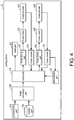
- FIG. 4 is a block diagram showing the function configuration of the printing device 2 according to Embodiment 1.
- FIG. 5A to FIG. 5D are diagrams showing relationships between pulse signals from a Y-axis encoder 68 and count values counted by a Y-axis counter 70 according to Embodiment 1.
- the printing device 2 includes a communication part 54, a storage part 56, an image processing part 58, the head part 20, an X-axis driving part 60, the X-axis motor 32, an X-axis encoder 62, an X-axis counter 64, a Y-axis driving part 66, the Y-axis motor 40, the Y-axis encoder 68 (an example of an encoder), the Y-axis counter 70 (an example of a counter), a determination part 72, and a control part 74.
- the head part 20 the X-axis motor 32 and the Y-axis motor 40 have been described, description thereof is omitted here.
- the communication part 54 performs wireless communication with an external terminal (not shown) such as a smartphone or a tablet terminal. Specifically, the communication part 54 receives, for example, a print start signal for instructing the printing device 2 to start printing from the external terminal. The communication part 54 outputs the received print start signal and the like to the image processing part 58.
- an external terminal not shown
- the communication part 54 receives, for example, a print start signal for instructing the printing device 2 to start printing from the external terminal.
- the communication part 54 outputs the received print start signal and the like to the image processing part 58.
- the storage part 56 is a memory for storing image data to be printed.
- the image processing part 58 Based on the print start signal from the communication part 54, the image processing part 58 reads the image data stored in the storage part 56, and performs image processing on the read image data. The image processing part 58 outputs the image data that has undergone image processing to the control part 74.
- the X-axis driving part 60 is a motor driver for driving the X-axis motor 32. That is, the X-axis driving part 60 causes the head part 20 to move in the main scanning direction with respect to the nail 10 of the finger 8 by applying a voltage to the X-axis motor 32.
- the X-axis encoder 62 outputs an A-phase pulse signal and a B-phase pulse signal corresponding to the position of the head part 20 in the main scanning direction.
- the X-axis encoder 62 is, for example, a linear encoder arranged on the moving table 28.
- the A-phase pulse signal and the B-phase pulse signal have a phase difference of 90°.
- the X-axis encoder 62 outputs the A-phase pulse signal and the B-phase pulse signal to the X-axis counter 64.
- the X-axis counter 64 counts a count value based on the A-phase pulse signal and the B-phase pulse signal from the X-axis encoder 62.
- the X-axis counter 64 outputs the counted count value to the control part 74.
- the Y-axis driving part 66 is a motor driver for driving the Y-axis motor 40. That is, the Y-axis driving part 66 causes the head part 20 to move in the sub-scanning direction with respect to the nail 10 of the finger 8 by applying a voltage to the Y-axis motor 40.
- the Y-axis encoder 68 outputs an A-phase pulse signal (an example of a first pulse signal) and a B-phase pulse signal (an example of a second pulse signal) corresponding to the position of the head part 20 in the sub-scanning direction.
- the Y-axis encoder 68 is, for example, a rotary encoder arranged on the worm wheel 44.
- the A-phase pulse signal and the B-phase pulse signal have a phase difference of 90° (an example of a predetermined phase difference).
- the Y-axis encoder 68 outputs the A-phase pulse signal and the B-phase pulse signal to the Y-axis counter 70.
- the Y-axis counter 70 counts a count value based on the A-phase pulse signal and the B-phase pulse signal from the Y-axis encoder 68. In addition, when the head part 20 is moving forward in the sub-scanning direction (toward minus direction of Y-axis), the Y-axis counter 70 counts up the count value. Meanwhile, when the head part 20 is moving backward in the sub-scanning direction (toward plus direction of Y-axis), the Y-axis counter 70 counts down the count value. The Y-axis counter 70 outputs the counted count value to the determination part 72 and the control part 74.
- the count value counted by the Y-axis counter 70 is specifically described with reference to FIG. 5A to FIG. 5D .
- the Y-axis encoder 68 When the Y-axis encoder 68 is normal and the head part 20 is moving forward in the sub-scanning direction, as shown in (d) and (e) of FIG. 5A , the Y-axis encoder 68 outputs an A-phase pulse signal and a B-phase pulse signal.
- the Y-axis counter 70 counts up the count value by "1" in a manner such as “1” ⁇ “2" ⁇ “3” ⁇ "4"... at each timing of the rise edge and the fall edge of the A-phase pulse signal and the rise edge and the fall edge of the B-phase pulse signal.
- the Y-axis encoder 68 when the Y-axis encoder 68 is normal and the head part 20 is moving backward in the sub-scanning direction, as shown in (d) and (e) of FIG. 5B , the Y-axis encoder 68 outputs an A-phase pulse signal and a B-phase pulse signal.
- the Y-axis counter 70 counts down the count value by "1" in a manner such as “7” ⁇ “6” ⁇ "5" ⁇ "4"... at each timing of the rise edge and the fall edge of the A-phase pulse signal and the rise edge and the fall edge of the B-phase pulse signal.
- the Y-axis encoder 68 when the Y-axis encoder 68 is abnormal (A-phase pulse signal is missing) and the head part 20 is moving forward or backward in the sub-scanning direction, as shown in (d) and (e) of FIG. 5C , the Y-axis encoder 68 outputs only a B-phase pulse signal.
- the Y-axis counter 70 counts up and counts down the count value repeatedly in a manner such as "1" ⁇ "0" ⁇ "1” ⁇ “0”... at each timing of the rise edge and the fall edge of the B-phase pulse signal.
- the Y-axis encoder 68 when the Y-axis encoder 68 is abnormal (B-phase pulse signal is missing) and the head part 20 is moving forward or backward in the sub-scanning direction, as shown in (d) and (e) of FIG. 5D , the Y-axis encoder 68 outputs only an A-phase pulse signal.
- the Y-axis counter 70 counts up and counts down the count value repeatedly in a manner such as "0" ⁇ "1” ⁇ "0” ⁇ “1”... at each timing of the rise edge and the fall edge of the A-phase pulse signal.
- the Y-axis encoder 68 when the Y-axis encoder 68 is abnormal (both the A-phase pulse signal and the B-phase pulse signal are missing) and the head part 20 is moving forward or backward in the sub-scanning direction, the Y-axis encoder 68 outputs neither the A-phase pulse signal nor the B-phase pulse signal.
- the count value counted by the Y-axis counter 70 is constant at "0" in a manner such as "0" ⁇ "0" ⁇ "0” ⁇ "0"...
- the determination part 72 determines whether or not there is an abnormality in the Y-axis encoder 68 based on the count value counted up by the Y-axis counter 70.
- the determination part 72 determines that the Y-axis encoder 68 is normal.
- counting up to a count value equal to or greater than 4 means that there are four kinds of combinations of the transition of each waveform of the A-phase pulse signal and the B-phase pulse signal, as shown in FIG. 5A for example. Therefore, it is considered that both the A-phase pulse signal and the B-phase pulse signal are normally output from the Y-axis encoder 68.
- the determination part 72 determines that the Y-axis encoder 68 is abnormal.
- counting up to a count value less than 4 means that there are not four combinations of the transition of each waveform of the A-phase pulse signal and the B-phase pulse signal, as shown in FIG. 5C and FIG. 5D for example. Therefore, it is considered that at least one of the A-phase pulse signal and the B-phase pulse signal is not normally output from the Y-axis encoder 68.
- the control part 74 performs the first control and a second control.
- the first control is a control for driving the Y-axis driving part 66 (Y-axis motor 40) in order to determine in advance whether or not there is an abnormality in the Y-axis encoder 68 by the determination part 72 before the second control (for example, a printing operation).
- the control part 74 drives the Y-axis driving part 66 so as to apply a constant voltage (for example, about 9.6 V) to the Y-axis motor 40 for a first time (for example, 30 milliseconds) regardless of the count value from the Y-axis counter 70.
- the control part 74 does not perform feedback control based on the count value from the Y-axis counter 70 when driving the Y-axis driving part 66.
- the head part 20 moves forward in the sub-scanning direction by a first distance (for example, 1 mm or less).
- the first time is, for example, a constant time measured by a timer.
- the second control is control for driving the head part 20, the X-axis driving part 60 (X-axis motor 32) and the Y-axis driving part 66 (Y-axis motor 40) in order that the nail 10 of the finger 8 is printed based on the image data from the image processing part 58 after the first control.
- the control part 74 drives the X-axis driving part 60 so as to apply a predetermined voltage to the X-axis motor 32 for a second time (for example, several seconds to several tens of seconds) longer than the first time based on the count value from the X-axis counter 64.
- the control part 74 performs feedback control based on the count value from the X-axis counter 64 when driving the X-axis driving part 60. Further, in the second control, the control part 74 drives the Y-axis driving part 66 so as to apply a predetermined voltage to the Y-axis motor 40 for the second time longer than the first time based on the count value from the Y-axis counter 70. That is, in the second control, the control part 74 performs the feedback control based on the count value from the Y-axis counter 70 when driving the Y-axis driving part 66. Thereby, in the second control, the head part 20 moves forward in the sub-scanning direction by a second distance (for example, several centimeters) longer than the first distance.
- a second distance for example, several centimeters
- the control part 74 shifts from the first control to the second control. Meanwhile, when the determination part 72 determines in the first control that the Y-axis encoder 68 is abnormal, the control part 74 does not shift from the first control to the second control. Thereby, the control part 74 does not execute, for example, a printing operation as the second control.
- FIG. 6 is a flowchart showing the flow of the operation of the printing device 2 according to Embodiment 1.
- FIG. 7A is a diagram for explaining the operation of the printing device 2 according to Embodiment 1 when the Y-axis encoder 68 is normal.
- FIG. 7B is a diagram for explaining the operation of the printing device 2 according to Embodiment 1 when the Y-axis encoder 68 is abnormal.
- the control part 74 drives the Y-axis driving part 66 so as to apply the constant voltage to the Y-axis motor 40 for the first time regardless of the count value from the Y-axis counter 70 (S103). Thereby, the head part 20 moves forward in the sub-scanning direction.
- both the A-phase pulse signal and the B-phase pulse signal are output from the Y-axis encoder 68.
- the Y-axis encoder 68 is abnormal, as shown in (a) and (b) of FIG. 7B , the A-phase pulse signal is not output from the Y-axis encoder 68; alternatively, although not shown, the B-phase pulse signal (or both the A-phase pulse signal and the B-phase pulse signal) is not output from the Y-axis encoder 68.
- the operation returns to step S103 described above.
- the control part 74 ends the application of the constant voltage to the Y-axis motor 40 by stopping the driving of the Y-axis driving part 66 (S105).
- the head part 20 moves forward in the sub-scanning direction due to the driving force from the Y-axis driving part 66.
- the head part 20 moves forward in the sub-scanning direction due to inertia force. Thereby, the head part 20 moves forward by the first distance (for example, 1 mm or less) in the sub-scanning direction over the first time and the third time.
- the first distance for example, 1 mm or less
- the Y-axis counter 70 counts up the count value over the first time and the third time.
- the count-up of the count value by the Y-axis counter 70 ends (S106).
- the determination part 72 determines that the Y-axis encoder 68 is normal (S108). In this case, the control part 74 shifts from the first control to the second control (S109).
- step S107 when the Y-axis counter 70 counts up to a count value less than 4 over the first time and the third time (NO in S107), the determination part 72 determines that the Y-axis encoder 68 is abnormal (S110). In this case, the control part 74 ends the first control (S111), and does not shift from the first control to the second control.
- control part 74 performs the first control before the second control, it is possible to determine in advance whether or not there is an abnormality in the Y-axis encoder 68. Thereby, in the second control, it is possible to prevent the driving of the Y-axis driving part 66 by the control part 74 from becoming uncontrollable.
- the control part 74 does not perform the feedback control which drives the Y-axis driving part 66 based on the count value from the Y-axis counter 70.
- the control part 74 does not perform the feedback control which drives the Y-axis driving part 66 based on the count value from the Y-axis counter 70.
- FIG. 8 is a block diagram showing the function configuration of the printing device 2A according to Embodiment 2.
- the same constituent components as those in the above-described Embodiment 1 are designated by the same reference numerals, and the description thereof is omitted.
- the control part 74 drives the Y-axis driving part 66 in order that the head part 20 moves forward in the sub-scanning direction.
- a control part 74A of the printing device 2A according to Embodiment 2 drives the Y-axis driving part 66 in order that the head part 20 moves backward in the sub-scanning direction.
- a determination part 72A determines whether or not there is an abnormality in the Y-axis encoder 68 based on the count value counted down by the Y-axis counter 70.
- the determination part 72A determines that the Y-axis encoder 68 is normal.
- counting down to a count value equal to or greater than 4 means that there are four combinations of the transition of each waveform of the A-phase pulse signal and the B-phase pulse signal as shown in FIG. 5B , so that it is considered that both the A-phase pulse signal and the B-phase pulse signal are normally output from the Y-axis encoder 68.
- FIG. 9 is a flowchart showing the flow of the operation of the printing device 2A according to Embodiment 2.
- FIG. 10 is a diagram for explaining the operation of the printing device 2A according to Embodiment 2 when the Y-axis encoder 68 is normal.
- the control part 74A drives the Y-axis driving part 66 so as to apply a constant voltage to the Y-axis motor 40 for a first time regardless of the count value from the Y-axis counter 70 (S203). Thereby, the head part 20 moves backward in the sub-scanning direction.
- both the A-phase pulse signal and the B-phase pulse signal are output from the Y-axis encoder 68.
- the Y-axis encoder 68 is abnormal, at least one of the A-phase pulse signal and the B-phase pulse signal is not output from the Y-axis encoder 68.
- the operation returns to step S203 described above.
- the control part 74A ends the application of the constant voltage to the Y-axis motor 40 by stopping the driving of the Y-axis driving part 66 (S205).
- the head part 20 moves backward in the sub-scanning direction due to the driving force from the Y-axis driving part 66.
- the head part 20 moves backward in the sub-scanning direction due to inertia force. Thereby, the head part 20 moves backward by a first distance (for example, 1 mm or less) in the sub-scanning direction over the first time and the third time.
- a first distance for example, 1 mm or less
- the Y-axis counter 70 counts down the count value over the first time and the third time.
- the count-down of the count value by the Y-axis counter 70 ends (S206).
- the determination part 72A determines that the Y-axis encoder 68 is normal (S208). In this case, the control part 74A shifts from the first control the second control (S209).
- step S207 when the Y-axis counter 70 counts down to a count value less than 4 over the first time and the third time (NO in S207), the determination part 72A determines that the Y-axis encoder 68 is abnormal (S210). In this case, the control part 74A ends the first control (S211) and does not shift from the first control to the second control.
- FIG. 11 is a block diagram showing the function configuration of the printing device 2B according to Embodiment 3.
- a control part 74B of the printing device 2B drives the Y-axis driving part 66 in order that the head part 20 moves forward in the sub-scanning direction (an example of a first direction).
- the control part 74B reverses the moving direction of the head part 20 in accordance with the count value counted by the Y-axis counter 70 and drives the Y-axis driving part 66 in order that the head part 20 moves backward in the sub-scanning direction (an example of a second direction).
- a determination part 72B determines whether or not there is an abnormality in the Y-axis encoder 68 based on the count value counted by the Y-axis counter 70.
- FIG. 12 is a flowchart showing the flow of the operation of the printing device 2B according to Embodiment 3.
- FIG. 13 is a diagram for explaining the operation of the printing device 2B according to Embodiment 3.
- the first control by the control part 74B starts (S301), and the count-up of the count value by the Y-axis counter 70 starts (S302).
- the control part 74B drives the Y-axis driving part 66 so as to apply a constant voltage to the Y-axis motor 40 for a first time regardless of the count value from the Y-axis counter 70 (S303). Thereby, the head part 20 moves forward in the sub-scanning direction.
- the Y-axis counter 70 counts up the count value over the first time and a third time (inertia period). When the third time has elapsed, the count-up of the count value by the Y-axis counter 70 ends (S306).
- the determination part 72B determines that the Y-axis encoder 68 is normal (S308). In this case, the control part 74B shifts from the first control to the second control (S309).
- step S307 when the Y-axis counter 70 counts up to a count value less than 4 over the first time and the third time (NO in S307), the count-down of the count value by the Y-axis counter 70 starts (S310). In addition, at this timing, the determination part 72B does not determine that the Y-axis encoder 68 is abnormal.
- the Y-axis counter 70 when the Y-axis counter 70 counts up to a count value less than 4, it is not possible to determine whether it is a) a case in which the Y-axis encoder 68 is normal, but as shown in FIG. 13 for example, the head part 20 contacts with the front surface 4b of the housing 4 and cannot physically move, or b) a case in which the Y-axis encoder 68 is abnormal. Therefore, in this case, as described below, whether or not there is an abnormality in the Y-axis encoder 68 is determined after reversing the moving direction of the head part 20 from the front to the back in the sub-scanning direction.
- the control part 74B drives the Y-axis driving part 66 so as to apply the constant voltage to the Y-axis motor 40 for the first time regardless of the count value from the Y-axis counter 70 (S311). Thereby, the head part 20 moves backward in the sub-scanning direction.
- the Y-axis counter 70 counts down the count value over the first time and the third time (inertia period). When the third time has elapsed, the count-down of the count value by the Y-axis counter 70 ends (S314).
- the determination part 72B determines that the Y-axis encoder 68 is normal (S308). In this case, the control part 74B shifts from the first control to the second control (S309).
- step S315 when the Y-axis counter 70 counts down to a count value less than 4 over the first time and the third time (NO in S315), the determination part 72B determines that the Y-axis encoder 68 is abnormal (S316). In this case, the control part 74B ends the first control (S317), and does not shift from the first control to the second control.
- control part 74B may cause the head part 20 to only move backward in the sub-scanning direction without causing the head part 20 to move forward in the sub-scanning direction. That is, steps S302 to S307 described above may be omitted.
- FIG. 14 is a block diagram showing the function configuration of the printing device 2C according to Embodiment 4.
- a control part 74C of the printing device 2C drives the Y-axis driving part 66 in order that the head part 20 moves backward in the sub-scanning direction (an example of the first direction).
- the control part 74C reverses the moving direction of the head part 20 in accordance with the count value counted by the Y-axis counter 70 and drives the Y-axis driving part 66 in order that the head part 20 moves forward in the sub-scanning direction (an example of the second direction).
- a determination part 72C determines whether or not there is an abnormality in the Y-axis encoder 68 based on the count value counted by the Y-axis counter 70.
- FIG. 15 is a flowchart showing the flow of the operation of the printing device 2C according to Embodiment 4.
- FIG. 16 is a diagram for explaining the operation of the printing device 2C according to Embodiment 4.
- the first control by the control part 74C starts (S401), and the count-down of the count value by the Y-axis counter 70 starts (S402).
- the control part 74C drives the Y-axis driving part 66 so as to apply a constant voltage to the Y-axis motor 40 for a first time regardless of the count value from the Y-axis counter 70 (S403). Thereby, the head part 20 moves backward in the sub-scanning direction.
- the Y-axis counter 70 counts down the count value over the first time and a third time (inertia period). When the third time has elapsed, the count-down of the count value by the Y-axis counter 70 ends (S406).
- the determination part 72C determines that the Y-axis encoder 68 is normal (S408). In this case, the control part 74C shifts from the first control to the second control (S409).
- step S407 when the Y-axis counter 70 counts down to a count value less than 4 over the first time and the third time (NO in S407), the count-up of the count value by the Y-axis counter 70 starts (S410). In addition, at this timing, the determination part 72C does not determine that the Y-axis encoder 68 is abnormal.
- the Y-axis counter 70 counts down to a count value less than 4, it is not possible to determine whether it is a) a case in which the Y-axis encoder 68 is normal, but as shown in FIG. 16 for example, the head part 20 contacts with a rear surface 4c (a surface opposite to the front surface 4b) of the housing 4 and cannot physically move, or b) a case in which the Y-axis encoder 68 is abnormal. Therefore, in this case, as described below, whether or not there is an abnormality in the Y-axis encoder 68 is determined after reversing the moving direction of the head part 20 from the back to the front in the sub-scanning direction.
- the control part 74C drives the Y-axis driving part 66 so as to apply the constant voltage to the Y-axis motor 40 for the first time regardless of the count value from the Y-axis counter 70 (S411). Thereby, the head part 20 moves forward in the sub-scanning direction.
- the Y-axis counter 70 counts up the count value over the first time and the third time (inertia period). When the third time has elapsed, the count-up of the count value by the Y-axis counter 70 ends (S314).
- the determination part 72C determines that the Y-axis encoder 68 is normal (S408). In this case, the control part 74C shifts from the first control to the second control (S409).
- step S415 when the Y-axis counter 70 counts up to a count value less than 4 over the first time and the third time (NO in S415), the determination part 72C determines that the Y-axis encoder 68 is abnormal (S416). In this case, the control part 74C ends the first control (S417) and does not shift from the first control to the second control.
- control part 74C may cause the head part 20 to only move forward in the sub-scanning direction without causing the head part 20 to move backward in the sub-scanning direction. That is, steps S402 to S407 described above may be omitted.
- the determination part 72 determines whether or not there is an abnormality in the Y-axis encoder 68 when the head part 20 moves in the sub-scanning direction, but the invention is not limited to this. For example, a determination may be made on whether or not there is an abnormality in the X-axis encoder 62 when the head part 20 moves in the main scanning direction (an example of the predetermined direction).
- the determination part 72 may determine whether or not there is an abnormality in a Z-axis encoder (not shown) which outputs a pulse signal corresponding to the position of the head part 20 in the vertical direction. In these cases, the same effect as described above can also be obtained.
- the Y-axis encoder 68 is a circular rotary encoder, but the invention is not limited to this.
- the Y-axis encoder 68 may be, for example, a band-shaped linear encoder as long as it outputs a pulse signal corresponding to the position of the head part 20 in the sub-scanning direction.
- the determination part 72 determines whether or not there is an abnormality in the Y-axis encoder 68 based on the absolute value of the count value counted by the Y-axis counter 70, but the invention is not limited to this. When the increasing/decreasing direction of the count value does not match the moving direction of the head part 20, it may be determined that the Y-axis encoder 68 is abnormal.
- the Y-axis encoder 68 is configured to output pulse signals of two phases (A-phase pulse signal and B-phase pulse signal), but the invention is not limited to this.
- the Y-axis encoder 68 may be configured to output only one-phase pulse signal or pulse signals of three phases or more.
- the first time is set to be a constant time, but the invention is not limited to this.
- the first time may be changed to be shorter by the control part 74 (74A, 74B, 74C) while an initial rise edge of the A-phase pulse signal or the B-phase pulse signal is detected in the first control.
- control part 74 (74A, 74B, 74C) performs the second control after the elapse of the third time, but the invention is not limited to this.
- control part 74 (74A, 74B, 74C) may execute the second control after the elapse of the first time.
- the invention can be applied as, for example, a printing device for performing printing for manicure use on a nail of a finger of a user's hand, and the like.
Abstract
Description
- The invention relates to a printing device for performing printing on a recording medium.
- A printing device for performing printing on a recording medium by an inkjet method has been known (for example, see patent literature 1). This type of printing device includes a head part that ejects ink toward the recording medium, a driving mechanism that causes the head part to move with respect to the recording medium in a main scanning direction and in a sub-scanning direction substantially orthogonal to the main scanning direction, an encoder that outputs an encoder signal corresponding to the position of the head part in the main scanning direction and the sub-scanning direction, and a control part that performs feedback control which drives the driving mechanism based on the encoder signal from the encoder.
- The printing device described above further includes an abnormality detection part that detects whether the encoder signal is normally output from the encoder during printing operation.
- Patent literature 1: Japanese Patent Application Laid-open No.
2003-145877 - In the conventional printing device described above, for example, when the encoder signal is not normally output from the encoder due to a failure of the encoder, the control part may further continue to drive the driving mechanism because there is no feedback of the encoder signal from the encoder. As a result, there is a problem that the driving of the driving mechanism by the control part may become uncontrollable before an abnormality is detected by the abnormality detection.
- The invention provides a printing device that can determine in advance whether or not there is an abnormality in an encoder before a second control performed by a control part.
- A printing device according to one aspect of the invention for performing printing on a recording medium includes: a head part that ejects ink toward the recording medium; a driving source that causes the head part to move in a predetermined direction with respect to the recording medium; an encoder that outputs a pulse signal corresponding to the position of the head part in the predetermined direction; a counter that counts a count value based on the pulse signal from the encoder; a control part that performs a first control which drives the driving source by applying a voltage to the driving source for a first time, and performs a second control which controls the driving source by applying a voltage to the driving source for a second time longer than the first time based on the count value from the counter; and a determination part which determines that the encoder is normal when the counter counts to a count value equal to or greater than a predetermined number and determines that the encoder is abnormal when the counter counts to a count value less than the predetermined number in the first control. The control part shifts from the first control to the second control when the determination part determines that the encoder is normal, and the control part does not shift from the first control to the second control when the determination part determines that the encoder is abnormal.
- According to the aspect, when the determination part determines that the encoder is normal in the first control, the control part shifts from the first control to the second control, and when the determination part determines that the encoder is abnormal in the first control, the control part does not shift from the first control to the second control. Thereby, it is possible to determine in advance whether or not there is an abnormality in the encoder before the second control performed by the control part. As a result, in the second control, it is possible to prevent the driving of the driving source by the control part from becoming uncontrollable.
- For example, in the printing device according to one aspect of the invention, the encoder may output a first pulse signal and a second pulse signal which have a predetermined phase difference, and the counter may count the count value based on the rise and fall of the first pulse signal and the rise and fall of the second pulse signal.
- According to the aspect, when the output of the encoder has a plurality of phases (first pulse signal and second pulse signal), it is possible to determine whether or not there is an abnormality in the encoder for all the phases.
- For example, in the printing device according to one aspect of the invention, in the first control, the determination part may determine that the encoder is normal when a count value equal to or greater than 4 is counted, and may determine that the encoder is abnormal when a count value less than 4 is counted.
- According to the aspect, when the output of the encoder has a plurality of phases, it is possible to precisely determine whether or not there is an abnormality in the encoder for all the phases.
- For example, in the printing device according to one aspect of the invention, in the first control, the control part may drive the driving source by applying a constant voltage to the driving source for the first time regardless of the count value from the counter.
- According to the aspect, the control part does not perform a feedback control which drives the driving source based on the count value from the counter in the first control. Thereby, even if the encoder breaks down, it is possible to cause the head part to move by a distance necessary for detecting whether or not there is an abnormality in the encoder without causing the head part to run away.
- For example, in the printing device according to one aspect of the invention, in the first control, the control part may drive the driving source so as to cause the head part to move by 1 mm or less by applying the constant voltage to the driving source for the first time.
- According to the aspect, in the first control, it is possible to cause the head part to move by 1 mm or less as a minimum distance necessary for detecting whether or not there is an abnormality in the encoder.
- For example, in the printing device according to one aspect of the invention, in the first control, the determination part may detect whether or not there is an abnormality in the encoder over the first time in which the control part applies the voltage to the driving source, and a third time in which the control part does not apply the voltage to the driving source after the elapse of the first time.
- According to the aspect, in the first control, the determination part detects whether or not there is an abnormality in the encoder over the first time in which the head part moves due to a driving force from the driving source and the third time in which the head part moves due to inertia. Therefore, even when the first time is set to be relatively short (for example, about several tens of milliseconds), it is possible to sufficiently secure a moving distance of the head part for detecting whether or not there is an abnormality in the encoder.
- For example, in the printing device according to one aspect of the invention, in the first control, while the control part controls the driving source so as to cause the head part to move in a first direction, the determination part may not determine that the encoder is abnormal when the counter counts to a count value less than the predetermined number, and while the control part continues to controls the driving source so as to cause the head part to move in a second direction opposite to the first direction based on the determination result of the determination part, the determination part may determine that the encoder is abnormal when the counter counts to a count value less than the predetermined number.
- According to the aspect, in the first control, when the counter counts to a count value less than the predetermined number, it is not possible to determine whether it is a) a case in which the encoder is normal, but for example, the head part contacts with a housing of the printing device or the like and cannot physically move, or b) a case in which the encoder is abnormal. Therefore, in this case, by determining whether or not there is an abnormality in the encoder after reversing the moving direction of the head part from the first direction to the second direction, it is possible to prevent the determination part from erroneously determining the abnormality of the encoder in the former case described above.
- According to the printing device of one aspect of the invention, it is possible to determine in advance whether or not there is an abnormality in the encoder before the second control performed by the control part.
-
-
FIG. 1 is a perspective view showing an appearance of a printing device according toEmbodiment 1. -
FIG. 2 is a perspective view showing a printing unit of the printing device according to Embodiment 1. -
FIG. 3 is a perspective view showing the printing unit of the printing device according toEmbodiment 1 with a head part and an X-axis driving mechanism omitted. -
FIG. 4 is a block diagram showing the function configuration of the printing device according toEmbodiment 1. -
FIG. 5A is a diagram showing a relationship between pulse signals from a Y-axis encoder and count values counted by a Y-axis counter according toEmbodiment 1. -
FIG. 5B is a diagram showing a relationship between pulse signals from the Y-axis encoder and count values counted by the Y-axis counter according toEmbodiment 1. -
FIG. 5C is a diagram showing a relationship between pulse signals from the Y-axis encoder and count values counted by the Y-axis counter according toEmbodiment 1. -
FIG. 5D is a diagram showing a relationship between pulse signals from the Y-axis encoder and count values counted by the Y-axis counter according toEmbodiment 1. -
FIG. 6 is a flowchart showing the flow of the operation of the printing device according toEmbodiment 1. -
FIG. 7A is a diagram for explaining the operation of the printing device according toEmbodiment 1 when the Y-axis encoder is normal. -
FIG. 7B is a diagram for explaining the operation of the printing device according toEmbodiment 1 when the Y-axis encoder is abnormal. -
FIG. 8 is a block diagram showing the function configuration of a printing device according toEmbodiment 2. -
FIG. 9 is a flowchart showing the flow of the operation of the printing device according toEmbodiment 2. -
FIG. 10 is a diagram for explaining the operation of the printing device according toEmbodiment 2 when the Y-axis encoder is normal. -
FIG. 11 is a block diagram showing the function configuration of a printing device according toEmbodiment 3. -
FIG. 12 is a flowchart showing the flow of the operation of the printing device according toEmbodiment 3. -
FIG. 13 is a diagram for explaining the operation of the printing device according toEmbodiment 3. -
FIG. 14 is a block diagram showing the function configuration of a printing device according toEmbodiment 4. -
FIG. 15 is a flowchart showing the flow of the operation of the printing device according toEmbodiment 4. -
FIG. 16 is a diagram for explaining the operation of the printing device according toEmbodiment 4. - Hereinafter, embodiments of the invention are described in detail with reference to the drawings. In addition, each of the embodiments described below shows a comprehensive or specific example. Numerical values, shapes, materials, constituent components, arrangement positions and connection forms of the constituent components and the like shown in the following embodiments are examples and are not intended to limit the invention. Further, among the constituent components in the following embodiments, constituent components not listed in independent claims are described as arbitrary constituent components.
- First, the structure of a
printing device 2 according toEmbodiment 1 is described with reference toFIG. 1 to FIG. 3 .FIG. 1 is a perspective view showing an appearance of theprinting device 2 according toEmbodiment 1.FIG. 2 is a perspective view showing aprinting unit 6 of theprinting device 2 according toEmbodiment 1.FIG. 3 is a perspective view showing theprinting unit 6 of theprinting device 2 according toEmbodiment 1 with ahead part 20 and anX-axis driving mechanism 22a omitted. - In addition, in
FIG. 1 to FIG. 3 , the width direction (left-right direction) of theprinting device 2 is described as an X-axis direction, the depth direction (front-back direction) of theprinting device 2 is described as a Y-axis direction, and the height direction of theprinting device 2 is described as a Z-axis direction. Further, for convenience of description, inFIG. 2 andFIG. 3 , a part of ahousing 4 is cut away. - As shown in
FIG. 1 to FIG. 3 , theprinting device 2 includes thehousing 4 and theprinting unit 6 arranged inside thehousing 4. In the embodiment, theprinting device 2 refers to a nail printer for performing printing for manicure use of color or pattern on anail 10 of afinger 8 of a user's hand (an example of a recording medium). - In addition, the
printing device 2 can wirelessly communicate with an external terminal (not shown) such as a smartphone or a tablet terminal. The user can operate theprinting device 2 by using an application installed in the external terminal as an interface. - As shown in
FIG. 1 , thehousing 4 is made of resin for example, and is formed into a box shape. Apower switch 12 for turning on/off the power of theprinting device 2 is arranged on atop surface 4a of thehousing 4. - As shown in
FIG. 1 , anopening 14 for inserting thefinger 8 of the user is formed on afront surface 4b of thehousing 4. As shown inFIG. 1 to FIG. 3 , afinger holder 16 for placing thefinger 8 of the user is arranged on the lower side of the opening 14 (minus side of Z axis). Further, as shown inFIG. 1 , apressing cover 18 for pressing thefinger 8 of the user from above is arranged on the upper side of the opening 14 (plus side of Z-axis). Thefinger holder 16 is movable in the vertical direction (Z-axis direction) with respect to thepressing cover 18, and is urged by a spring (not shown) in a direction approaching thepressing cover 18. - As shown in
FIG. 2 andFIG. 3 , the user inserts thefinger 8 into the opening 14 (seeFIG. 1 ) of thehousing 4 while thefinger 8 is extended straightly with thenail 10 of thefinger 8 facing upward, and places the pulp side of thefinger 8 on thefinger holder 16. Thereby, a part of thefinger 8 including the nail 10 (for example, a part of thefinger 8 from tip to vicinity of the first joint) is arranged inside thehousing 4. At this time, thefinger holder 16 is urged in the direction approaching thepressing cover 18, and thereby for example the vicinity of the first joint of thefinger 8 is clamped from above and below by thefinger holder 16 and thepressing cover 18. - The
printing unit 6 is a unit for performing printing for manicure use on thenail 10 of thefinger 8 arranged inside thehousing 4. The printing method of theprinting unit 6 is an inkjet method in which mist-like ink is sprayed on thenail 10 of thefinger 8 to thereby perform printing. As shown inFIG. 2 , theprinting unit 6 has ahead part 20 and adriving mechanism 22. - The
head part 20 has acarriage 24 and anink tank 26 mounted on thecarriage 24. Theink tank 26 is filled with four types of ink inside, for example, CMYK (C: cyan, M: magenta, Y: yellow, K: black). A nozzle surface (not shown) from which the ink supplied from theink tank 26 is ejected downward toward thenail 10 of thefinger 8 is formed on the lower surface of thecarriage 24. - The
driving mechanism 22 is a mechanism for causing thehead part 20 to two-dimensionally move in a main scanning direction (X-axis direction) and a sub-scanning direction (Y-axis direction) substantially orthogonal to the main scanning direction (an example of a predetermined direction). As shown inFIG. 2 andFIG. 3 , thedriving mechanism 22 has anX-axis driving mechanism 22a for causing thehead part 20 to move in the main scanning direction with respect to thenail 10 of thefinger 8, and a Y-axis driving mechanism 22b for causing thehead part 20 to move in the sub-scanning direction with respect to thenail 10 of thefinger 8. - As shown in
FIG. 2 , theX-axis driving mechanism 22a has a moving table 28, anX-axis guide shaft 30, anX-axis motor 32, and atiming belt 34. - The
X-axis guide shaft 30 is supported by the moving table 28 arranged inside thehousing 4, and extends into an elongated shape in the X-axis direction. Thehead part 20 is movably supported on theX-axis guide shaft 30. TheX-axis motor 32 is configured by, for example, a servo motor, and is supported by the lower surface of the moving table 28. - A driving force of the
X-axis motor 32 is transmitted to thehead part 20 via thetiming belt 34. Thereby, thehead part 20 moves in the X-axis direction along theX-axis guide shaft 30 with respect to the moving table 28. - As shown in
FIG. 3 , the Y-axis driving mechanism 22b has the moving table 28 (seeFIG. 2 ), a bearingmember 36, a Y-axis guide shaft 38, a Y-axis motor 40 (an example of a driving source), aworm gear 42, aworm wheel 44 and adriving conversion mechanism 46. - The Y-
axis guide shaft 38 is supported by abase frame 48 arranged inside thehousing 4, and extends into an elongated shape in the Y-axis direction. The bearingmember 36 fixed to the lower surface of the moving table 28 is movably supported on the Y-axis guide shaft 38. That is, the moving table 28 is movably supported by the Y-axis guide shaft 38 via the bearingmember 36. The Y-axis motor 40 is configured by, for example, a servo motor, and is supported by thebase frame 48. Theworm gear 42 is rotatably supported by a driving shaft of the Y-axis motor 40. Theworm wheel 44 is rotatably supported by thebase frame 48 and meshes with theworm gear 42. - The
driving conversion mechanism 46 is a mechanism for converting rotation of theworm wheel 44 into linear movement of thehead part 20 in the Y-axis direction. Thedriving conversion mechanism 46 has apinion gear 50 formed on theworm wheel 44 and arack gear 52 formed on the bearingmember 36. Thepinion gear 50 and therack gear 52 mesh with each other. - A driving force of the Y-
axis motor 40 is transmitted to the moving table 28 via theworm gear 42, theworm wheel 44, thepinion gear 50 and therack gear 52. Thereby, thehead part 20 moves integrally with the moving table 28 in the Y-axis direction along the Y-axis guide shaft 38. - While the
head part 20 reciprocates in the main scanning direction and is moving from the other side toward one side (from plus side to minus side of Y-axis) in the sub-scanning direction, the ink is ejected from the nozzle surface of thehead part 20 toward thenail 10 of the finger, and thereby the printing is performed on thenail 10 of thefinger 8. - Next, the function configuration of the
printing device 2 according toEmbodiment 1 is described with reference toFIG. 4 to FIG. 5D .FIG. 4 is a block diagram showing the function configuration of theprinting device 2 according toEmbodiment 1.FIG. 5A to FIG. 5D are diagrams showing relationships between pulse signals from a Y-axis encoder 68 and count values counted by a Y-axis counter 70 according toEmbodiment 1. - As shown in
FIG. 4 , theprinting device 2 includes acommunication part 54, astorage part 56, animage processing part 58, thehead part 20, anX-axis driving part 60, theX-axis motor 32, anX-axis encoder 62, anX-axis counter 64, a Y-axis driving part 66, the Y-axis motor 40, the Y-axis encoder 68 (an example of an encoder), the Y-axis counter 70 (an example of a counter), adetermination part 72, and acontrol part 74. In addition, because thehead part 20, theX-axis motor 32 and the Y-axis motor 40 have been described, description thereof is omitted here. - The
communication part 54 performs wireless communication with an external terminal (not shown) such as a smartphone or a tablet terminal. Specifically, thecommunication part 54 receives, for example, a print start signal for instructing theprinting device 2 to start printing from the external terminal. Thecommunication part 54 outputs the received print start signal and the like to theimage processing part 58. - The
storage part 56 is a memory for storing image data to be printed. - Based on the print start signal from the
communication part 54, theimage processing part 58 reads the image data stored in thestorage part 56, and performs image processing on the read image data. Theimage processing part 58 outputs the image data that has undergone image processing to thecontrol part 74. - The
X-axis driving part 60 is a motor driver for driving theX-axis motor 32. That is, theX-axis driving part 60 causes thehead part 20 to move in the main scanning direction with respect to thenail 10 of thefinger 8 by applying a voltage to theX-axis motor 32. - The
X-axis encoder 62 outputs an A-phase pulse signal and a B-phase pulse signal corresponding to the position of thehead part 20 in the main scanning direction. TheX-axis encoder 62 is, for example, a linear encoder arranged on the moving table 28. The A-phase pulse signal and the B-phase pulse signal have a phase difference of 90°. TheX-axis encoder 62 outputs the A-phase pulse signal and the B-phase pulse signal to theX-axis counter 64. - The X-axis counter 64 counts a count value based on the A-phase pulse signal and the B-phase pulse signal from the
X-axis encoder 62. TheX-axis counter 64 outputs the counted count value to thecontrol part 74. - The Y-
axis driving part 66 is a motor driver for driving the Y-axis motor 40. That is, the Y-axis driving part 66 causes thehead part 20 to move in the sub-scanning direction with respect to thenail 10 of thefinger 8 by applying a voltage to the Y-axis motor 40. - The Y-
axis encoder 68 outputs an A-phase pulse signal (an example of a first pulse signal) and a B-phase pulse signal (an example of a second pulse signal) corresponding to the position of thehead part 20 in the sub-scanning direction. The Y-axis encoder 68 is, for example, a rotary encoder arranged on theworm wheel 44. The A-phase pulse signal and the B-phase pulse signal have a phase difference of 90° (an example of a predetermined phase difference). The Y-axis encoder 68 outputs the A-phase pulse signal and the B-phase pulse signal to the Y-axis counter 70. - The Y-
axis counter 70 counts a count value based on the A-phase pulse signal and the B-phase pulse signal from the Y-axis encoder 68. In addition, when thehead part 20 is moving forward in the sub-scanning direction (toward minus direction of Y-axis), the Y-axis counter 70 counts up the count value. Meanwhile, when thehead part 20 is moving backward in the sub-scanning direction (toward plus direction of Y-axis), the Y-axis counter 70 counts down the count value. The Y-axis counter 70 outputs the counted count value to thedetermination part 72 and thecontrol part 74. - Here, the count value counted by the Y-
axis counter 70 is specifically described with reference toFIG. 5A to FIG. 5D . - When the Y-
axis encoder 68 is normal and thehead part 20 is moving forward in the sub-scanning direction, as shown in (d) and (e) ofFIG. 5A , the Y-axis encoder 68 outputs an A-phase pulse signal and a B-phase pulse signal. - Here, as shown in (a) to (c) of
FIG. 5A , as the combination of the transition of each waveform of the A-phase pulse signal and the B-phase pulse signal, there are four kinds of combinations: i) the A-phase pulse signal rises, and the B-phase pulse signal is constant (combination number = 1); ii) the A-phase pulse signal is constant, and the B-phase pulse signal rises (combination number = 2); iii) the A-phase pulse signal falls, and the B-phase pulse signal is constant (combination number = 3); and iv) the A-phase pulse signal is constant, and the B-phase pulse signal falls (combination number = 4). - In this case, as shown in (f) of
FIG. 5A , the Y-axis counter 70 counts up the count value by "1" in a manner such as "1" → "2" → "3" → "4"... at each timing of the rise edge and the fall edge of the A-phase pulse signal and the rise edge and the fall edge of the B-phase pulse signal. - Further, when the Y-
axis encoder 68 is normal and thehead part 20 is moving backward in the sub-scanning direction, as shown in (d) and (e) ofFIG. 5B , the Y-axis encoder 68 outputs an A-phase pulse signal and a B-phase pulse signal. - Here, as shown in (a) to (c) of
FIG. 5B , as the combination of the transition of each waveform of the A-phase pulse signal and the B-phase pulse signal, there are four kinds of combinations: i) the A-phase pulse signal is constant, and the B-phase pulse signal rises (combination number = 2); ii) the A-phase pulse signal rises, and the B-phase pulse signal is constant (combination number = 1); iii) the A-phase pulse signal is constant, and the B-phase pulse signal falls (combination number = 4); and iv) the A-phase pulse signal falls, and the B-phase pulse signal is constant (combination number = 3). - In this case, as shown in (f) of
FIG. 5B , the Y-axis counter 70 counts down the count value by "1" in a manner such as "7" → "6" → "5" → "4"... at each timing of the rise edge and the fall edge of the A-phase pulse signal and the rise edge and the fall edge of the B-phase pulse signal. - Further, when the Y-
axis encoder 68 is abnormal (A-phase pulse signal is missing) and thehead part 20 is moving forward or backward in the sub-scanning direction, as shown in (d) and (e) ofFIG. 5C , the Y-axis encoder 68 outputs only a B-phase pulse signal. - Here, as shown in (a) to (c) of
FIG. 5C , as the combination of the transition of each waveform of the A-phase pulse signal and the B-phase pulse signal, there are two kinds of combinations: i) the A-phase pulse signal is constant, and the B-phase pulse signal rises (combination number = 2); and ii) the A-phase pulse signal is constant, and the B-phase pulse signal falls (combination number = 4). - In this case, as shown in (f) of
FIG. 5C , the Y-axis counter 70 counts up and counts down the count value repeatedly in a manner such as "1" → "0" → "1" → "0"... at each timing of the rise edge and the fall edge of the B-phase pulse signal. - Further, when the Y-
axis encoder 68 is abnormal (B-phase pulse signal is missing) and thehead part 20 is moving forward or backward in the sub-scanning direction, as shown in (d) and (e) ofFIG. 5D , the Y-axis encoder 68 outputs only an A-phase pulse signal. - Here, as shown in (a) to (c) of
FIG. 5D , as the combination of the transition of each waveform of the A-phase pulse signal and the B-phase pulse signal, there are two kinds of combinations: i) the A-phase pulse signal rises, and the B-phase pulse signal is constant (combination number = 1); and ii) the A-phase pulse signal falls, and the B-phase pulse signal is constant (combination number = 3). - In this case, as shown in (f) of
FIG. 5D , the Y-axis counter 70 counts up and counts down the count value repeatedly in a manner such as "0" → "1" → "0" → "1"... at each timing of the rise edge and the fall edge of the A-phase pulse signal. - Further, although not shown, when the Y-
axis encoder 68 is abnormal (both the A-phase pulse signal and the B-phase pulse signal are missing) and thehead part 20 is moving forward or backward in the sub-scanning direction, the Y-axis encoder 68 outputs neither the A-phase pulse signal nor the B-phase pulse signal. In this case, the count value counted by the Y-axis counter 70 is constant at "0" in a manner such as "0" → "0" → "0" → "0"... - Returning to
FIG. 4 , in a first control (described later) by thecontrol part 74, when thehead part 20 is moving forward in the sub-scanning direction, thedetermination part 72 determines whether or not there is an abnormality in the Y-axis encoder 68 based on the count value counted up by the Y-axis counter 70. - Specifically, when the Y-
axis counter 70 counts up to a count value equal to or greater than 4 (an example of being equal to or greater than a predetermined number) in a manner such as the count value "1" → "2" → "3" → "4"... shown in (f) ofFIG. 5A , thedetermination part 72 determines that the Y-axis encoder 68 is normal. In addition, counting up to a count value equal to or greater than 4 means that there are four kinds of combinations of the transition of each waveform of the A-phase pulse signal and the B-phase pulse signal, as shown inFIG. 5A for example. Therefore, it is considered that both the A-phase pulse signal and the B-phase pulse signal are normally output from the Y-axis encoder 68. - Meanwhile, when the Y-
axis counter 70 counts up to a count value less than 4 (an example of being less than the predetermined number) in a manner such as the count value "0" → "1" shown in (f) ofFIG. 5C and (f) ofFIG. 5D , thedetermination part 72 determines that the Y-axis encoder 68 is abnormal. In addition, counting up to a count value less than 4 means that there are not four combinations of the transition of each waveform of the A-phase pulse signal and the B-phase pulse signal, as shown inFIG. 5C and FIG. 5D for example. Therefore, it is considered that at least one of the A-phase pulse signal and the B-phase pulse signal is not normally output from the Y-axis encoder 68. - The
control part 74 performs the first control and a second control. - The first control is a control for driving the Y-axis driving part 66 (Y-axis motor 40) in order to determine in advance whether or not there is an abnormality in the Y-
axis encoder 68 by thedetermination part 72 before the second control (for example, a printing operation). In the first control, thecontrol part 74 drives the Y-axis driving part 66 so as to apply a constant voltage (for example, about 9.6 V) to the Y-axis motor 40 for a first time (for example, 30 milliseconds) regardless of the count value from the Y-axis counter 70. That is, in the first control, thecontrol part 74 does not perform feedback control based on the count value from the Y-axis counter 70 when driving the Y-axis driving part 66. Thereby, in the first control, thehead part 20 moves forward in the sub-scanning direction by a first distance (for example, 1 mm or less). In addition, the first time is, for example, a constant time measured by a timer. - The second control is control for driving the
head part 20, the X-axis driving part 60 (X-axis motor 32) and the Y-axis driving part 66 (Y-axis motor 40) in order that thenail 10 of thefinger 8 is printed based on the image data from theimage processing part 58 after the first control. In the second control, thecontrol part 74 drives theX-axis driving part 60 so as to apply a predetermined voltage to theX-axis motor 32 for a second time (for example, several seconds to several tens of seconds) longer than the first time based on the count value from theX-axis counter 64. That is, in the second control, thecontrol part 74 performs feedback control based on the count value from the X-axis counter 64 when driving theX-axis driving part 60. Further, in the second control, thecontrol part 74 drives the Y-axis driving part 66 so as to apply a predetermined voltage to the Y-axis motor 40 for the second time longer than the first time based on the count value from the Y-axis counter 70. That is, in the second control, thecontrol part 74 performs the feedback control based on the count value from the Y-axis counter 70 when driving the Y-axis driving part 66. Thereby, in the second control, thehead part 20 moves forward in the sub-scanning direction by a second distance (for example, several centimeters) longer than the first distance. - When the
determination part 72 determines in the first control that the Y-axis encoder 68 is normal, thecontrol part 74 shifts from the first control to the second control. Meanwhile, when thedetermination part 72 determines in the first control that the Y-axis encoder 68 is abnormal, thecontrol part 74 does not shift from the first control to the second control. Thereby, thecontrol part 74 does not execute, for example, a printing operation as the second control. - Next, the operation of the
printing device 2 according toEmbodiment 1 is described with reference toFIG. 6 to FIG. 7B .FIG. 6 is a flowchart showing the flow of the operation of theprinting device 2 according toEmbodiment 1.FIG. 7A is a diagram for explaining the operation of theprinting device 2 according toEmbodiment 1 when the Y-axis encoder 68 is normal.FIG. 7B is a diagram for explaining the operation of theprinting device 2 according toEmbodiment 1 when the Y-axis encoder 68 is abnormal. - As shown in
FIG. 6 , first, the first control by thecontrol part 74 starts (S101), and the count-up of the count value by the Y-axis counter 70 starts (S102). As shown in (c) ofFIG. 7A and (c) ofFIG. 7B , thecontrol part 74 drives the Y-axis driving part 66 so as to apply the constant voltage to the Y-axis motor 40 for the first time regardless of the count value from the Y-axis counter 70 (S103). Thereby, thehead part 20 moves forward in the sub-scanning direction. - Here, when the Y-
axis encoder 68 is normal, as shown in (a) and (b) ofFIG. 7A , both the A-phase pulse signal and the B-phase pulse signal are output from the Y-axis encoder 68. Meanwhile, when the Y-axis encoder 68 is abnormal, as shown in (a) and (b) ofFIG. 7B , the A-phase pulse signal is not output from the Y-axis encoder 68; alternatively, although not shown, the B-phase pulse signal (or both the A-phase pulse signal and the B-phase pulse signal) is not output from the Y-axis encoder 68. - When the first time has not elapsed since the constant voltage was applied to the Y-axis motor 40 (NO in S104), the operation returns to step S103 described above. When the first time has elapsed since the constant voltage was applied to the Y-axis motor 40 (YES in S104), the
control part 74 ends the application of the constant voltage to the Y-axis motor 40 by stopping the driving of the Y-axis driving part 66 (S105). In addition, during the first time in which the constant voltage is applied to the Y-axis motor 40, thehead part 20 moves forward in the sub-scanning direction due to the driving force from the Y-axis driving part 66. During a third time (for example, 70 milliseconds) (inertia period) in which the constant voltage is not applied to the Y-axis motor 40 after the elapse of the first time, thehead part 20 moves forward in the sub-scanning direction due to inertia force. Thereby, thehead part 20 moves forward by the first distance (for example, 1 mm or less) in the sub-scanning direction over the first time and the third time. - In the first control, the Y-
axis counter 70 counts up the count value over the first time and the third time. When the third time has elapsed, the count-up of the count value by the Y-axis counter 70 ends (S106). - When the Y-
axis counter 70 counts up to a count value equal to or greater than 4 over the first time and the third time (YES in S107), thedetermination part 72 determines that the Y-axis encoder 68 is normal (S108). In this case, thecontrol part 74 shifts from the first control to the second control (S109). - Returning to step S107, when the Y-
axis counter 70 counts up to a count value less than 4 over the first time and the third time (NO in S107), thedetermination part 72 determines that the Y-axis encoder 68 is abnormal (S110). In this case, thecontrol part 74 ends the first control (S111), and does not shift from the first control to the second control. - As described above, because the
control part 74 performs the first control before the second control, it is possible to determine in advance whether or not there is an abnormality in the Y-axis encoder 68. Thereby, in the second control, it is possible to prevent the driving of the Y-axis driving part 66 by thecontrol part 74 from becoming uncontrollable. - Further, in the first control, the
control part 74 does not perform the feedback control which drives the Y-axis driving part 66 based on the count value from the Y-axis counter 70. Thereby, even if the Y-axis encoder 68 breaks down, it is possible to cause thehead part 20 to move by the first distance (for example, 1 mm or less) necessary for detecting whether or not there is an abnormality in the Y-axis encoder 68 without causing thehead part 20 to run away. As a result, it is possible to prevent the moving table 28 from running away forward in the sub-scanning direction and contacting with thenail 10 of thefinger 8. - The function configuration of a
printing device 2A according toEmbodiment 2 is described with reference toFIG. 8. FIG. 8 is a block diagram showing the function configuration of theprinting device 2A according toEmbodiment 2. In addition, in each of the following embodiments, the same constituent components as those in the above-describedEmbodiment 1 are designated by the same reference numerals, and the description thereof is omitted. - In
Embodiment 1, in the first control, thecontrol part 74 drives the Y-axis driving part 66 in order that thehead part 20 moves forward in the sub-scanning direction. Conversely, as shown inFIG. 8 , in the first control, acontrol part 74A of theprinting device 2A according toEmbodiment 2 drives the Y-axis driving part 66 in order that thehead part 20 moves backward in the sub-scanning direction. - In the first control by the
control part 74A, when thehead part 20 is moving backward in the sub-scanning direction, adetermination part 72A determines whether or not there is an abnormality in the Y-axis encoder 68 based on the count value counted down by the Y-axis counter 70. - Specifically, when the Y-
axis counter 70 counts down to a count value equal to or greater than 4 in a manner such as the count value "7" → "6" → "5" → "4"... shown in (f) ofFIG. 5B described above, thedetermination part 72A determines that the Y-axis encoder 68 is normal. In addition, counting down to a count value equal to or greater than 4 means that there are four combinations of the transition of each waveform of the A-phase pulse signal and the B-phase pulse signal as shown inFIG. 5B , so that it is considered that both the A-phase pulse signal and the B-phase pulse signal are normally output from the Y-axis encoder 68. - Next, the operation of the
printing device 2A according toEmbodiment 2 is described with reference toFIG. 9 andFIG. 10 .FIG. 9 is a flowchart showing the flow of the operation of theprinting device 2A according toEmbodiment 2.FIG. 10 is a diagram for explaining the operation of theprinting device 2A according toEmbodiment 2 when the Y-axis encoder 68 is normal. - As shown in
FIG. 9 , first, the first control by thecontrol part 74A starts (S201), and the count-down of the count value by the Y-axis counter 70 starts (S202). As shown in (c) ofFIG. 10 , thecontrol part 74A drives the Y-axis driving part 66 so as to apply a constant voltage to the Y-axis motor 40 for a first time regardless of the count value from the Y-axis counter 70 (S203). Thereby, thehead part 20 moves backward in the sub-scanning direction. - Here, when the Y-
axis encoder 68 is normal, as shown in (a) and (b) ofFIG. 10 , both the A-phase pulse signal and the B-phase pulse signal are output from the Y-axis encoder 68. Meanwhile, although not shown, when the Y-axis encoder 68 is abnormal, at least one of the A-phase pulse signal and the B-phase pulse signal is not output from the Y-axis encoder 68. - When the first time (for example, 30 milliseconds) has not elapsed since the constant voltage was applied to the Y-axis motor 40 (NO in S204), the operation returns to step S203 described above. When the first time has elapsed since the constant voltage was applied to the Y-axis motor 40 (YES in S204), the
control part 74A ends the application of the constant voltage to the Y-axis motor 40 by stopping the driving of the Y-axis driving part 66 (S205). In addition, during the first time in which the constant voltage is applied to the Y-axis motor 40, thehead part 20 moves backward in the sub-scanning direction due to the driving force from the Y-axis driving part 66. During a third time (for example, 70 milliseconds) (inertia period) in which the constant voltage is not applied to the Y-axis motor 40 after the elapse of the first time, thehead part 20 moves backward in the sub-scanning direction due to inertia force. Thereby, thehead part 20 moves backward by a first distance (for example, 1 mm or less) in the sub-scanning direction over the first time and the third time. - In the first control, the Y-
axis counter 70 counts down the count value over the first time and the third time. When the third time has elapsed, the count-down of the count value by the Y-axis counter 70 ends (S206). - When the Y-
axis counter 70 counts down to a count value equal to or greater than 4 over the first time and the third time (YES in S207), thedetermination part 72A determines that the Y-axis encoder 68 is normal (S208). In this case, thecontrol part 74A shifts from the first control the second control (S209). - Returning to step S207, when the Y-
axis counter 70 counts down to a count value less than 4 over the first time and the third time (NO in S207), thedetermination part 72A determines that the Y-axis encoder 68 is abnormal (S210). In this case, thecontrol part 74A ends the first control (S211) and does not shift from the first control to the second control. - In the embodiment, it is also possible to obtain the same effect as that of
Embodiment 1. - The function configuration of a
printing device 2B according toEmbodiment 3 is described with reference toFIG. 11. FIG. 11 is a block diagram showing the function configuration of theprinting device 2B according toEmbodiment 3. - As shown in
FIG. 11 , in the first control, acontrol part 74B of theprinting device 2B according toEmbodiment 3 drives the Y-axis driving part 66 in order that thehead part 20 moves forward in the sub-scanning direction (an example of a first direction). At this time, thecontrol part 74B reverses the moving direction of thehead part 20 in accordance with the count value counted by the Y-axis counter 70 and drives the Y-axis driving part 66 in order that thehead part 20 moves backward in the sub-scanning direction (an example of a second direction). - In the first control, when the
head part 20 is moving forward or backward in the sub-scanning direction, adetermination part 72B determines whether or not there is an abnormality in the Y-axis encoder 68 based on the count value counted by the Y-axis counter 70. - Next, the operation of the
printing device 2B according toEmbodiment 3 is described with reference toFIG. 12 andFIG. 13 .FIG. 12 is a flowchart showing the flow of the operation of theprinting device 2B according toEmbodiment 3.FIG. 13 is a diagram for explaining the operation of theprinting device 2B according toEmbodiment 3. - As shown in
FIG. 12 , first, the first control by thecontrol part 74B starts (S301), and the count-up of the count value by the Y-axis counter 70 starts (S302). Thecontrol part 74B drives the Y-axis driving part 66 so as to apply a constant voltage to the Y-axis motor 40 for a first time regardless of the count value from the Y-axis counter 70 (S303). Thereby, thehead part 20 moves forward in the sub-scanning direction. - When the first time has not elapsed since the constant voltage was applied to the Y-axis motor 40 (NO in S304), the operation returns to step S303 described above. When the first time has elapsed since the constant voltage was applied to the Y-axis motor 40 (YES in S304), the
control part 74B ends the application of the constant voltage to the Y-axis motor 40 by stopping the driving of the Y-axis driving part 66 (S305). - In the first control, the Y-
axis counter 70 counts up the count value over the first time and a third time (inertia period). When the third time has elapsed, the count-up of the count value by the Y-axis counter 70 ends (S306). - When the Y-
axis counter 70 counts up to a count value equal to or greater than 4 over the first time and the third time (YES in S307), thedetermination part 72B determines that the Y-axis encoder 68 is normal (S308). In this case, thecontrol part 74B shifts from the first control to the second control (S309). - Returning to step S307, when the Y-
axis counter 70 counts up to a count value less than 4 over the first time and the third time (NO in S307), the count-down of the count value by the Y-axis counter 70 starts (S310). In addition, at this timing, thedetermination part 72B does not determine that the Y-axis encoder 68 is abnormal. - In addition, in the first control, when the Y-
axis counter 70 counts up to a count value less than 4, it is not possible to determine whether it is a) a case in which the Y-axis encoder 68 is normal, but as shown inFIG. 13 for example, thehead part 20 contacts with thefront surface 4b of thehousing 4 and cannot physically move, or b) a case in which the Y-axis encoder 68 is abnormal. Therefore, in this case, as described below, whether or not there is an abnormality in the Y-axis encoder 68 is determined after reversing the moving direction of thehead part 20 from the front to the back in the sub-scanning direction. - The
control part 74B drives the Y-axis driving part 66 so as to apply the constant voltage to the Y-axis motor 40 for the first time regardless of the count value from the Y-axis counter 70 (S311). Thereby, thehead part 20 moves backward in the sub-scanning direction. - When the first time has not elapsed since the constant voltage was applied to the Y-axis motor 40 (NO in S312), the operation returns to step S311 described above. When the first time has elapsed since the constant voltage was applied to the Y-axis motor 40 (YES in S312), the
control part 74B ends the application of the constant voltage to the Y-axis motor 40 by stopping the driving of the Y-axis driving part 66 (S313). - In the first control, the Y-
axis counter 70 counts down the count value over the first time and the third time (inertia period). When the third time has elapsed, the count-down of the count value by the Y-axis counter 70 ends (S314). - When the Y-
axis counter 70 counts down to a count value equal to or greater than 4 over the first time and the third time (YES in S315), thedetermination part 72B determines that the Y-axis encoder 68 is normal (S308). In this case, thecontrol part 74B shifts from the first control to the second control (S309). - Returning to step S315, when the Y-
axis counter 70 counts down to a count value less than 4 over the first time and the third time (NO in S315), thedetermination part 72B determines that the Y-axis encoder 68 is abnormal (S316). In this case, thecontrol part 74B ends the first control (S317), and does not shift from the first control to the second control. - In the embodiment, when the Y-
axis encoder 68 is normal, but as shown inFIG. 13 for example, thehead part 20 contacts with thefront surface 4b of thehousing 4 and cannot physically move, it is possible to prevent thedetermination part 72B from erroneously determining the abnormality of the Y-axis encoder 68. - In addition, when a sensor or the like which detects that the
head part 20 is in contact with thefront surface 4b of thehousing 4 is arranged inside thehousing 4, based on a detection result from the sensor or the like, thecontrol part 74B may cause thehead part 20 to only move backward in the sub-scanning direction without causing thehead part 20 to move forward in the sub-scanning direction. That is, steps S302 to S307 described above may be omitted. - The function configuration of a
printing device 2C according toEmbodiment 4 is described with reference toFIG. 14. FIG. 14 is a block diagram showing the function configuration of theprinting device 2C according toEmbodiment 4. - As shown in
FIG. 14 , in the first control, acontrol part 74C of theprinting device 2C according toEmbodiment 4 drives the Y-axis driving part 66 in order that thehead part 20 moves backward in the sub-scanning direction (an example of the first direction). At this time, thecontrol part 74C reverses the moving direction of thehead part 20 in accordance with the count value counted by the Y-axis counter 70 and drives the Y-axis driving part 66 in order that thehead part 20 moves forward in the sub-scanning direction (an example of the second direction). - In the first control, when the
head part 20 is moving forward or backward in the sub-scanning direction, adetermination part 72C determines whether or not there is an abnormality in the Y-axis encoder 68 based on the count value counted by the Y-axis counter 70. - Next, the operation of the
printing device 2C according toEmbodiment 4 is described with reference toFIG. 15 andFIG. 16 .FIG. 15 is a flowchart showing the flow of the operation of theprinting device 2C according toEmbodiment 4.FIG. 16 is a diagram for explaining the operation of theprinting device 2C according toEmbodiment 4. - As shown in
FIG. 15 , first, the first control by thecontrol part 74C starts (S401), and the count-down of the count value by the Y-axis counter 70 starts (S402). Thecontrol part 74C drives the Y-axis driving part 66 so as to apply a constant voltage to the Y-axis motor 40 for a first time regardless of the count value from the Y-axis counter 70 (S403). Thereby, thehead part 20 moves backward in the sub-scanning direction. - When the first time has not elapsed since the constant voltage was applied to the Y-axis motor 40 (NO in S404), the operation returns to step S403 described above. When the first time has elapsed since the constant voltage was applied to the Y-axis motor 40 (YES in S404), the
control part 74C ends the application of the constant voltage to the Y-axis motor 40 by stopping the driving of the Y-axis driving part 66 (S405). - In the first control, the Y-
axis counter 70 counts down the count value over the first time and a third time (inertia period). When the third time has elapsed, the count-down of the count value by the Y-axis counter 70 ends (S406). - When the Y-
axis counter 70 counts down to a count value equal to or greater than 4 over the first time and the third time (YES in S407), thedetermination part 72C determines that the Y-axis encoder 68 is normal (S408). In this case, thecontrol part 74C shifts from the first control to the second control (S409). - Returning to step S407, when the Y-
axis counter 70 counts down to a count value less than 4 over the first time and the third time (NO in S407), the count-up of the count value by the Y-axis counter 70 starts (S410). In addition, at this timing, thedetermination part 72C does not determine that the Y-axis encoder 68 is abnormal. - In addition, in the first control, when the Y-
axis counter 70 counts down to a count value less than 4, it is not possible to determine whether it is a) a case in which the Y-axis encoder 68 is normal, but as shown inFIG. 16 for example, thehead part 20 contacts with arear surface 4c (a surface opposite to thefront surface 4b) of thehousing 4 and cannot physically move, or b) a case in which the Y-axis encoder 68 is abnormal. Therefore, in this case, as described below, whether or not there is an abnormality in the Y-axis encoder 68 is determined after reversing the moving direction of thehead part 20 from the back to the front in the sub-scanning direction. - The
control part 74C drives the Y-axis driving part 66 so as to apply the constant voltage to the Y-axis motor 40 for the first time regardless of the count value from the Y-axis counter 70 (S411). Thereby, thehead part 20 moves forward in the sub-scanning direction. - When the first time has not elapsed since the constant voltage was applied to the Y-axis motor 40 (NO in S412), the operation returns to step S411 described above. When the first time has elapsed since the constant voltage was applied to the Y-axis motor 40 (YES in S412), the
control part 74C ends the application of the constant voltage to the Y-axis motor 40 by stopping the driving of the Y-axis driving part 66 (S413). - In the first control, the Y-
axis counter 70 counts up the count value over the first time and the third time (inertia period). When the third time has elapsed, the count-up of the count value by the Y-axis counter 70 ends (S314). - When the Y-
axis counter 70 counts up to a count value equal to or greater than 4 over the first time and the third time (YES in S415), thedetermination part 72C determines that the Y-axis encoder 68 is normal (S408). In this case, thecontrol part 74C shifts from the first control to the second control (S409). - Returning to step S415, when the Y-
axis counter 70 counts up to a count value less than 4 over the first time and the third time (NO in S415), thedetermination part 72C determines that the Y-axis encoder 68 is abnormal (S416). In this case, thecontrol part 74C ends the first control (S417) and does not shift from the first control to the second control. - In the embodiment, when the Y-
axis encoder 68 is normal, but as shown inFIG. 16 for example, thehead part 20 contacts with therear surface 4c of thehousing 4 and cannot physically move, it is possible to prevent thedetermination part 72C from erroneously determining the abnormality of the Y-axis encoder 68. - In addition, when a sensor or the like which detects that the
head part 20 is in contact with therear surface 4c of thehousing 4 is arranged inside thehousing 4, based on a detection result from the sensor or the like, thecontrol part 74C may cause thehead part 20 to only move forward in the sub-scanning direction without causing thehead part 20 to move backward in the sub-scanning direction. That is, steps S402 to S407 described above may be omitted. - In the above, the printing devices according to the first to fourth embodiments of the invention have been described, but the invention is not limited to each of the above embodiments. For example, each of the above embodiments may be combined respectively.
- In each of the above embodiments, the determination part 72 (72A, 72B, 72C) determines whether or not there is an abnormality in the Y-
axis encoder 68 when thehead part 20 moves in the sub-scanning direction, but the invention is not limited to this. For example, a determination may be made on whether or not there is an abnormality in theX-axis encoder 62 when thehead part 20 moves in the main scanning direction (an example of the predetermined direction). Alternatively, when thehead part 20 moves in a vertical direction (Z-axis direction) (an example of the predetermined direction), the determination part 72 (72A, 72B, 72C) may determine whether or not there is an abnormality in a Z-axis encoder (not shown) which outputs a pulse signal corresponding to the position of thehead part 20 in the vertical direction. In these cases, the same effect as described above can also be obtained. - In each of the above embodiments, the Y-
axis encoder 68 is a circular rotary encoder, but the invention is not limited to this. The Y-axis encoder 68 may be, for example, a band-shaped linear encoder as long as it outputs a pulse signal corresponding to the position of thehead part 20 in the sub-scanning direction. - In each of the above embodiments, the determination part 72 (72A, 72B, 72C) determines whether or not there is an abnormality in the Y-
axis encoder 68 based on the absolute value of the count value counted by the Y-axis counter 70, but the invention is not limited to this. When the increasing/decreasing direction of the count value does not match the moving direction of thehead part 20, it may be determined that the Y-axis encoder 68 is abnormal. - In each of the above embodiments, a case in which the printing operation is performed in the second control has been described, but the invention is not limited to this. In the second control, for example, a start operation or a maintenance operation of the printing device 2 (2A, 2B, 2C) may be performed.
- In each of the above embodiments, the Y-
axis encoder 68 is configured to output pulse signals of two phases (A-phase pulse signal and B-phase pulse signal), but the invention is not limited to this. For example, the Y-axis encoder 68 may be configured to output only one-phase pulse signal or pulse signals of three phases or more. - In each of the above embodiments, the first time is set to be a constant time, but the invention is not limited to this. For example, the first time may be changed to be shorter by the control part 74 (74A, 74B, 74C) while an initial rise edge of the A-phase pulse signal or the B-phase pulse signal is detected in the first control.
- In each of the above embodiments, the control part 74 (74A, 74B, 74C) performs the second control after the elapse of the third time, but the invention is not limited to this. For example, the control part 74 (74A, 74B, 74C) may execute the second control after the elapse of the first time.
- The invention can be applied as, for example, a printing device for performing printing for manicure use on a nail of a finger of a user's hand, and the like.
-
- 2, 2A, 2B, 2C:
- printing device
- 4:
- housing
- 4a:
- top surface
- 4b:
- front surface
- 4c:
- rear surface
- 6:
- printing unit
- 8:
- finger
- 10:
- nail
- 12:
- power switch
- 14:
- opening
- 16:
- finger holder
- 18:
- pressing cover
- 20:
- head
- 22:
- driving mechanism
- 22a:
- X-axis driving mechanism
- 22b:
- Y-axis driving mechanism
- 24:
- carriage
- 26:
- ink tank
- 28:
- moving table
- 30:
- X-axis guide shaft
- 32:
- X-axis motor
- 34:
- timing belt
- 36:
- bearing member
- 38:
- Y-axis guide shaft
- 40:
- Y-axis motor
- 42:
- worm gear
- 44:
- worm wheel
- 46:
- driving conversion mechanism
- 48:
- base frame
- 50:
- pinion gear
- 52:
- rack gear
- 54:
- communication part
- 56:
- storage part
- 58:
- image processing part
- 60:
- X-axis driving part
- 62:
- X-axis encoder
- 64:
- X-axis counter
- 66:
- Y-axis driving part
- 68:
- Y-axis encoder
- 70:
- Y-axis counter
- 72, 72A, 72B, 72C:
- determination part
- 74, 74A, 74B, 74C:
- control part
Claims (7)
- A printing device (2) for performing printing on a recording medium, characterized in that the printing device (2) comprises:a head part (20) that ejects ink toward the recording medium;a driving source (40) that causes the head part to move in a predetermined direction with respect to the recording medium;an encoder (68) that outputs a pulse signal corresponding to a position of the head part (20) in the predetermined direction;a counter (70) that counts a count value based on the pulse signal from the encoder (68);a control part (74) that performs a first control which drives the driving source by applying a voltage to the driving source for a first time, and performs a second control which controls the driving source (40) by applying a voltage to the driving source (40) for a second time longer than the first time based on the count value from the counter (68); anda determination part (72) which in the first control determines that the encoder is normal when the counter counts to a count value equal to or greater than a predetermined number, and determines that the encoder is abnormal when the counter counts to a count value less than the predetermined number,wherein the control part (74) shifts from the first control to the second control when the determination part (72) determines that the encoder is normal, and the control part does not shift from the first control to the second control when the determination part determines that the encoder is abnormal.
- The printing device (2) according to claim 1, characterized in that the encoder (68) outputs a first pulse signal and a second pulse signal which have a predetermined phase difference; and
wherein the counter (70) counts the count value based on a rise and a fall of the first pulse signal and a rise and a fall of the second pulse signal. - The printing device (2) according to claim 2, characterized in that in the first control, the determination part (72) determines that the encoder (68) is normal when a count value equal to or greater than 4 is counted, and determines that the encoder (68) is abnormal when a count value less than 4 is counted.
- The printing device (2) according to any one of claims 1 to 3, characterized in that in the first control, the control part (74) drives the driving source by applying a constant voltage to the driving source (40) for the first time regardless of the count value from the counter (70).
- The printing device (2) according to claim 4, characterized in that in the first control, the control part (74) drives the driving source (40) so as to cause the head part (20) to move by 1 mm or less by applying the constant voltage to the driving source (40) for the first time.
- The printing device (2) according to any one of claims 1 to 5, characterized in that in the first control, the determination part (72) detects whether or not there is an abnormality in the encoder (68) over the first time in which the control part (74) applies the voltage to the driving source (40), and a third time in which the control part (74) does not apply the voltage to the driving source (40) after an elapse of the first time.
- The printing device (2) according to any one of claims 1 to 6, characterized in that in the first control, while the control part (74) controls the driving source (40) so as to cause the head part to move in a first direction, the determination part (72) does not determine that the encoder (68) is abnormal when the counter (70) counts to a count value less than the predetermined number; and
while the control part (74) continues to controls the driving source (40) so as to cause the head part (20) to move in a second direction opposite to the first direction based on a determination result of the determination part (72), the determination part (72) determines that the encoder (68) is abnormal when the counter (70) counts to a count value less than the predetermined number.
Applications Claiming Priority (1)
| Application Number | Priority Date | Filing Date | Title |
|---|---|---|---|
| JP2019229904A JP7388173B2 (en) | 2019-12-20 | 2019-12-20 | printing device |
Publications (2)
| Publication Number | Publication Date |
|---|---|
| EP3838606A1 true EP3838606A1 (en) | 2021-06-23 |
| EP3838606B1 EP3838606B1 (en) | 2023-03-22 |
Family
ID=73288428
Family Applications (1)
| Application Number | Title | Priority Date | Filing Date |
|---|---|---|---|
| EP20206646.0A Active EP3838606B1 (en) | 2019-12-20 | 2020-11-10 | Printing device |
Country Status (4)
| Country | Link |
|---|---|
| US (1) | US11305528B2 (en) |
| EP (1) | EP3838606B1 (en) |
| JP (1) | JP7388173B2 (en) |
| CN (1) | CN113002196B (en) |
Citations (3)
| Publication number | Priority date | Publication date | Assignee | Title |
|---|---|---|---|---|
| JP2003145877A (en) | 2001-11-16 | 2003-05-21 | Copyer Co Ltd | Serial printer |
| JP2003299385A (en) * | 2002-03-29 | 2003-10-17 | Brother Ind Ltd | Motor control device and encoder failure detecting method |
| US20090153604A1 (en) * | 2007-12-18 | 2009-06-18 | Chao-Ming Chen | Printing Device and Method Using The Same |
Family Cites Families (3)
| Publication number | Priority date | Publication date | Assignee | Title |
|---|---|---|---|---|
| JP5610838B2 (en) * | 2010-05-11 | 2014-10-22 | キヤノン株式会社 | Equipment with motor |
| JP2013078917A (en) | 2011-10-05 | 2013-05-02 | Ricoh Co Ltd | Image forming apparatus |
| JP6217077B2 (en) | 2012-12-05 | 2017-10-25 | 株式会社リコー | Driving device and image forming apparatus |
-
2019
- 2019-12-20 JP JP2019229904A patent/JP7388173B2/en active Active
-
2020
- 2020-11-04 CN CN202011213925.6A patent/CN113002196B/en active Active
- 2020-11-06 US US17/090,898 patent/US11305528B2/en active Active
- 2020-11-10 EP EP20206646.0A patent/EP3838606B1/en active Active
Patent Citations (3)
| Publication number | Priority date | Publication date | Assignee | Title |
|---|---|---|---|---|
| JP2003145877A (en) | 2001-11-16 | 2003-05-21 | Copyer Co Ltd | Serial printer |
| JP2003299385A (en) * | 2002-03-29 | 2003-10-17 | Brother Ind Ltd | Motor control device and encoder failure detecting method |
| US20090153604A1 (en) * | 2007-12-18 | 2009-06-18 | Chao-Ming Chen | Printing Device and Method Using The Same |
Also Published As
| Publication number | Publication date |
|---|---|
| CN113002196A (en) | 2021-06-22 |
| JP7388173B2 (en) | 2023-11-29 |
| US11305528B2 (en) | 2022-04-19 |
| CN113002196B (en) | 2022-07-15 |
| JP2021098274A (en) | 2021-07-01 |
| US20210187939A1 (en) | 2021-06-24 |
| EP3838606B1 (en) | 2023-03-22 |
Similar Documents
| Publication | Publication Date | Title |
|---|---|---|
| US7775654B2 (en) | Printing apparatus, program, and printing method | |
| US7147299B2 (en) | Control unit and method for controlling motor for use in printer, and storage medium storing control program | |
| CA3021928C (en) | Activation method for a goods processing apparatus having an inkjet print head, and goods processing apparatus | |
| EP0767067A1 (en) | Printer with detachable printhead | |
| EP2581229A1 (en) | Image forming apparatus including sheet cutting device | |
| CN109159549A (en) | Print control program, control device, storage medium and printing device | |
| EP1905604A1 (en) | Printing apparatus | |
| CN102285223A (en) | Electronic device | |
| EP3838606B1 (en) | Printing device | |
| US8177320B2 (en) | Carriage and image forming device including carriage | |
| EP0659572A2 (en) | Printer and method of controlling it | |
| US20170326893A1 (en) | Printer | |
| JP2007002356A (en) | Fabric suspending frame and printer | |
| US7455380B2 (en) | Printing apparatus, media detection apparatus, media detection method, measurement method, computer-readable storage medium, and printing system | |
| EP0958923A2 (en) | Multipurpose printing apparatus | |
| JP5029181B2 (en) | Fluid ejecting apparatus and flushing control method for fluid ejecting apparatus | |
| JP2013099957A (en) | Opening/closing determination of opening of apparatus | |
| US8201937B2 (en) | Decision of opening and closing of opening section of apparatus | |
| US11203209B2 (en) | Electronic device, operation method and recording medium | |
| JP2007276135A (en) | Printer and printing method | |
| JPH0998245A (en) | Facsimile equipment | |
| US20080198201A1 (en) | Printing apparatus and printing control method | |
| JP5928692B2 (en) | Recording device | |
| JP2003063085A (en) | Printing controller and printing method | |
| EP1001362B1 (en) | A printer system |
Legal Events
| Date | Code | Title | Description |
|---|---|---|---|
| PUAI | Public reference made under article 153(3) epc to a published international application that has entered the european phase |
Free format text: ORIGINAL CODE: 0009012 |
|
| STAA | Information on the status of an ep patent application or granted ep patent |
Free format text: STATUS: THE APPLICATION HAS BEEN PUBLISHED |
|
| AK | Designated contracting states |
Kind code of ref document: A1 Designated state(s): AL AT BE BG CH CY CZ DE DK EE ES FI FR GB GR HR HU IE IS IT LI LT LU LV MC MK MT NL NO PL PT RO RS SE SI SK SM TR |
|
| STAA | Information on the status of an ep patent application or granted ep patent |
Free format text: STATUS: REQUEST FOR EXAMINATION WAS MADE |
|
| 17P | Request for examination filed |
Effective date: 20210810 |
|
| RBV | Designated contracting states (corrected) |
Designated state(s): AL AT BE BG CH CY CZ DE DK EE ES FI FR GB GR HR HU IE IS IT LI LT LU LV MC MK MT NL NO PL PT RO RS SE SI SK SM TR |
|
| GRAP | Despatch of communication of intention to grant a patent |
Free format text: ORIGINAL CODE: EPIDOSNIGR1 |
|
| STAA | Information on the status of an ep patent application or granted ep patent |
Free format text: STATUS: GRANT OF PATENT IS INTENDED |
|
| INTG | Intention to grant announced |
Effective date: 20230102 |
|
| GRAS | Grant fee paid |
Free format text: ORIGINAL CODE: EPIDOSNIGR3 |
|
| GRAA | (expected) grant |
Free format text: ORIGINAL CODE: 0009210 |
|
| STAA | Information on the status of an ep patent application or granted ep patent |
Free format text: STATUS: THE PATENT HAS BEEN GRANTED |
|
| AK | Designated contracting states |
Kind code of ref document: B1 Designated state(s): AL AT BE BG CH CY CZ DE DK EE ES FI FR GB GR HR HU IE IS IT LI LT LU LV MC MK MT NL NO PL PT RO RS SE SI SK SM TR |
|
| REG | Reference to a national code |
Ref country code: GB Ref legal event code: FG4D |
|
| REG | Reference to a national code |
Ref country code: CH Ref legal event code: EP |
|
| REG | Reference to a national code |
Ref country code: IE Ref legal event code: FG4D |
|
| REG | Reference to a national code |
Ref country code: DE Ref legal event code: R096 Ref document number: 602020009001 Country of ref document: DE |
|
| REG | Reference to a national code |
Ref country code: AT Ref legal event code: REF Ref document number: 1555079 Country of ref document: AT Kind code of ref document: T Effective date: 20230415 |
|
| REG | Reference to a national code |
Ref country code: LT Ref legal event code: MG9D |
|
| REG | Reference to a national code |
Ref country code: NL Ref legal event code: MP Effective date: 20230322 |
|
| PG25 | Lapsed in a contracting state [announced via postgrant information from national office to epo] |
Ref country code: RS Free format text: LAPSE BECAUSE OF FAILURE TO SUBMIT A TRANSLATION OF THE DESCRIPTION OR TO PAY THE FEE WITHIN THE PRESCRIBED TIME-LIMIT Effective date: 20230322 Ref country code: NO Free format text: LAPSE BECAUSE OF FAILURE TO SUBMIT A TRANSLATION OF THE DESCRIPTION OR TO PAY THE FEE WITHIN THE PRESCRIBED TIME-LIMIT Effective date: 20230622 Ref country code: LV Free format text: LAPSE BECAUSE OF FAILURE TO SUBMIT A TRANSLATION OF THE DESCRIPTION OR TO PAY THE FEE WITHIN THE PRESCRIBED TIME-LIMIT Effective date: 20230322 Ref country code: LT Free format text: LAPSE BECAUSE OF FAILURE TO SUBMIT A TRANSLATION OF THE DESCRIPTION OR TO PAY THE FEE WITHIN THE PRESCRIBED TIME-LIMIT Effective date: 20230322 Ref country code: HR Free format text: LAPSE BECAUSE OF FAILURE TO SUBMIT A TRANSLATION OF THE DESCRIPTION OR TO PAY THE FEE WITHIN THE PRESCRIBED TIME-LIMIT Effective date: 20230322 |
|
| REG | Reference to a national code |
Ref country code: AT Ref legal event code: MK05 Ref document number: 1555079 Country of ref document: AT Kind code of ref document: T Effective date: 20230322 |
|
| PG25 | Lapsed in a contracting state [announced via postgrant information from national office to epo] |
Ref country code: SE Free format text: LAPSE BECAUSE OF FAILURE TO SUBMIT A TRANSLATION OF THE DESCRIPTION OR TO PAY THE FEE WITHIN THE PRESCRIBED TIME-LIMIT Effective date: 20230322 Ref country code: NL Free format text: LAPSE BECAUSE OF FAILURE TO SUBMIT A TRANSLATION OF THE DESCRIPTION OR TO PAY THE FEE WITHIN THE PRESCRIBED TIME-LIMIT Effective date: 20230322 Ref country code: GR Free format text: LAPSE BECAUSE OF FAILURE TO SUBMIT A TRANSLATION OF THE DESCRIPTION OR TO PAY THE FEE WITHIN THE PRESCRIBED TIME-LIMIT Effective date: 20230623 Ref country code: FI Free format text: LAPSE BECAUSE OF FAILURE TO SUBMIT A TRANSLATION OF THE DESCRIPTION OR TO PAY THE FEE WITHIN THE PRESCRIBED TIME-LIMIT Effective date: 20230322 |
|
| PG25 | Lapsed in a contracting state [announced via postgrant information from national office to epo] |
Ref country code: SM Free format text: LAPSE BECAUSE OF FAILURE TO SUBMIT A TRANSLATION OF THE DESCRIPTION OR TO PAY THE FEE WITHIN THE PRESCRIBED TIME-LIMIT Effective date: 20230322 Ref country code: RO Free format text: LAPSE BECAUSE OF FAILURE TO SUBMIT A TRANSLATION OF THE DESCRIPTION OR TO PAY THE FEE WITHIN THE PRESCRIBED TIME-LIMIT Effective date: 20230322 Ref country code: PT Free format text: LAPSE BECAUSE OF FAILURE TO SUBMIT A TRANSLATION OF THE DESCRIPTION OR TO PAY THE FEE WITHIN THE PRESCRIBED TIME-LIMIT Effective date: 20230724 Ref country code: ES Free format text: LAPSE BECAUSE OF FAILURE TO SUBMIT A TRANSLATION OF THE DESCRIPTION OR TO PAY THE FEE WITHIN THE PRESCRIBED TIME-LIMIT Effective date: 20230322 Ref country code: EE Free format text: LAPSE BECAUSE OF FAILURE TO SUBMIT A TRANSLATION OF THE DESCRIPTION OR TO PAY THE FEE WITHIN THE PRESCRIBED TIME-LIMIT Effective date: 20230322 Ref country code: AT Free format text: LAPSE BECAUSE OF FAILURE TO SUBMIT A TRANSLATION OF THE DESCRIPTION OR TO PAY THE FEE WITHIN THE PRESCRIBED TIME-LIMIT Effective date: 20230322 |
|
| PG25 | Lapsed in a contracting state [announced via postgrant information from national office to epo] |
Ref country code: SK Free format text: LAPSE BECAUSE OF FAILURE TO SUBMIT A TRANSLATION OF THE DESCRIPTION OR TO PAY THE FEE WITHIN THE PRESCRIBED TIME-LIMIT Effective date: 20230322 Ref country code: PL Free format text: LAPSE BECAUSE OF FAILURE TO SUBMIT A TRANSLATION OF THE DESCRIPTION OR TO PAY THE FEE WITHIN THE PRESCRIBED TIME-LIMIT Effective date: 20230322 Ref country code: IS Free format text: LAPSE BECAUSE OF FAILURE TO SUBMIT A TRANSLATION OF THE DESCRIPTION OR TO PAY THE FEE WITHIN THE PRESCRIBED TIME-LIMIT Effective date: 20230722 |
|
| REG | Reference to a national code |
Ref country code: DE Ref legal event code: R097 Ref document number: 602020009001 Country of ref document: DE |
|
| PLBE | No opposition filed within time limit |
Free format text: ORIGINAL CODE: 0009261 |
|
| STAA | Information on the status of an ep patent application or granted ep patent |
Free format text: STATUS: NO OPPOSITION FILED WITHIN TIME LIMIT |
|
| PG25 | Lapsed in a contracting state [announced via postgrant information from national office to epo] |
Ref country code: SI Free format text: LAPSE BECAUSE OF FAILURE TO SUBMIT A TRANSLATION OF THE DESCRIPTION OR TO PAY THE FEE WITHIN THE PRESCRIBED TIME-LIMIT Effective date: 20230322 Ref country code: DK Free format text: LAPSE BECAUSE OF FAILURE TO SUBMIT A TRANSLATION OF THE DESCRIPTION OR TO PAY THE FEE WITHIN THE PRESCRIBED TIME-LIMIT Effective date: 20230322 Ref country code: CZ Free format text: LAPSE BECAUSE OF FAILURE TO SUBMIT A TRANSLATION OF THE DESCRIPTION OR TO PAY THE FEE WITHIN THE PRESCRIBED TIME-LIMIT Effective date: 20230322 |
|
| PGFP | Annual fee paid to national office [announced via postgrant information from national office to epo] |
Ref country code: DE Payment date: 20230929 Year of fee payment: 4 |
|
| 26N | No opposition filed |
Effective date: 20240102 |