EP3838525A1 - System for edge banding of panels - Google Patents
System for edge banding of panels Download PDFInfo
- Publication number
- EP3838525A1 EP3838525A1 EP20213706.3A EP20213706A EP3838525A1 EP 3838525 A1 EP3838525 A1 EP 3838525A1 EP 20213706 A EP20213706 A EP 20213706A EP 3838525 A1 EP3838525 A1 EP 3838525A1
- Authority
- EP
- European Patent Office
- Prior art keywords
- panel
- edge
- unit
- heating
- adhesive substance
- Prior art date
- Legal status (The legal status is an assumption and is not a legal conclusion. Google has not performed a legal analysis and makes no representation as to the accuracy of the status listed.)
- Pending
Links
- 238000010438 heat treatment Methods 0.000 claims abstract description 58
- 230000007480 spreading Effects 0.000 claims abstract description 34
- 238000003892 spreading Methods 0.000 claims abstract description 34
- 239000003292 glue Substances 0.000 claims abstract description 27
- 239000000853 adhesive Substances 0.000 claims abstract description 21
- 230000001070 adhesive effect Effects 0.000 claims abstract description 21
- 239000000126 substance Substances 0.000 claims abstract description 21
- 238000003825 pressing Methods 0.000 claims abstract description 15
- 239000011248 coating agent Substances 0.000 claims abstract description 6
- 238000000576 coating method Methods 0.000 claims abstract description 6
- 239000004033 plastic Substances 0.000 claims abstract description 4
- 239000011152 fibreglass Substances 0.000 claims abstract description 3
- 239000002023 wood Substances 0.000 claims abstract description 3
- 239000011159 matrix material Substances 0.000 claims description 7
- 230000004913 activation Effects 0.000 claims description 4
- 230000009849 deactivation Effects 0.000 claims description 4
- 230000005855 radiation Effects 0.000 claims description 4
- 238000001514 detection method Methods 0.000 description 5
- 230000008901 benefit Effects 0.000 description 4
- 230000003213 activating effect Effects 0.000 description 3
- 230000008878 coupling Effects 0.000 description 2
- 238000010168 coupling process Methods 0.000 description 2
- 238000005859 coupling reaction Methods 0.000 description 2
- 238000009826 distribution Methods 0.000 description 2
- 230000005670 electromagnetic radiation Effects 0.000 description 2
- 230000002860 competitive effect Effects 0.000 description 1
- 230000003247 decreasing effect Effects 0.000 description 1
- -1 for example Substances 0.000 description 1
- 229910052736 halogen Inorganic materials 0.000 description 1
- 150000002367 halogens Chemical class 0.000 description 1
- 238000004519 manufacturing process Methods 0.000 description 1
- 239000000463 material Substances 0.000 description 1
- 239000002184 metal Substances 0.000 description 1
- 230000004048 modification Effects 0.000 description 1
- 238000012986 modification Methods 0.000 description 1
- 238000012544 monitoring process Methods 0.000 description 1
- 238000001228 spectrum Methods 0.000 description 1
Images
Classifications
-
- B—PERFORMING OPERATIONS; TRANSPORTING
- B27—WORKING OR PRESERVING WOOD OR SIMILAR MATERIAL; NAILING OR STAPLING MACHINES IN GENERAL
- B27D—WORKING VENEER OR PLYWOOD
- B27D5/00—Other working of veneer or plywood specially adapted to veneer or plywood
- B27D5/003—Other working of veneer or plywood specially adapted to veneer or plywood securing a veneer strip to a panel edge
Definitions
- the present invention relates to a system for edge banding panels.
- the invention relates to a system of the above-mentioned type, designed and manufactured in particular to couple an edge banding tape to the side edge of a panel, but which can be used for any application in which edge banding on surfaces is required.
- edge banding systems generally installed on the sides of a sliding surface, on which the panels are made to slide.
- Said edge banding systems generally comprise rollers for spreading the glue on the edge of the panel while it is moving on the sliding plane, so that these rollers, sliding on the lateral edge of the panel, apply the glue; and pressure rollers to press the edge banding tape on the edge of the panel to be processed and to adhere the glue.
- the panel is further finished with appropriate cutters, in order to cut and round off the excess of the edge banding tape previously applied.
- This tape can be made of different materials such as, for example, plastic or metal, and has variable dimensions according to the size of the side surface of the same panel, on which it has to be applied.
- the rollers for spreading the glue on the edge of the panel and the pressure rollers are spaced from each other by a few centimeters or a few tens of centimeters.
- the latter will exert pressure on the edge banding tape to make it adhere to the edge of the panel only after a predetermined time interval, depending on the handling speed of the panel.
- Another object of the invention is to provide a system for the edge banding of panels, which allows the correct adhesion of the edge banding tape to the edge of the panel to be worked.
- a further object of the invention is to provide a system for the edge banding of panels, which allows the adhesion to be adjusted selectively on different points of the panel edge.
- Another object of the invention is to provide a system for the edge banding of panels that is highly reliable, relatively simple to manufacture, and at competitive costs if compared to the known art.
- a system for edge banding a panel such as a panel made of wood, fiberglass, plastic and the like by means of an edge banding tape
- said system being characterized in that it comprises a heating unit, interposed between said spreading unit and said pressing unit, wherein said heating unit is configured to heat selectively said adhesive substance spread on said edge of the said panel by said spreading unit.
- said heating unit may be facing said edge of said panel and comprises a plurality of heating elements.
- said heating elements may be arranged so as to form a matrix of heating elements.
- said system may comprise temperature sensing means, arranged in correspondence of said edge of said panel to which said adhesive substance is applied, wherein said temperature sensing means are capable of detecting the temperature of said adhesive substance spread on said edge of said panel, and a logic control unit, connected to said temperature sensing means and to said heating unit, wherein said logic control unit may be configured for receiving temperature values of said adhesive substance from said temperature sensing means, and sending at least one activation or deactivation signal to said heating unit to activate or deactivate one or more heating elements, so as to heat a respective portion of said edge, on which said adhesive substance is applied.
- said heating elements may be diodes or LASER.
- said diodes or LASER may be infrared radiation.
- said logic control unit may be configured to receive the movement relative speed of said panel with respect to said system for the edge banding of said panel, wherein said logic control unit is configured to drive said heating unit as a function of said speed.
- an edge banding system according to the present invention is shown, indicated as a whole with the reference letter S, which comprises a spreading unit 1 for spreading an adhesive substance on a lateral surface or edge B of a panel P, a pressing unit 3 to press an edge banding tape (not shown in the figures) onto said edge B, and a heating unit 2, interposed between said spreading unit 1 and said pressure 3, to heat said adhesive substance.
- the edge banding system S also comprises coupling means (not shown in the figures), for coupling to the edge of a moving plane (not shown in the figures), for moving the panel P to be edge banded.
- Said moving plane can be for example constituted by a plane with motorized rollers or with a belt.
- the spreading unit 1 allows spreading an adhesive substance, such as glue and the like, on at least one side surface or edge B of said panel P.
- said spreading unit 1 comprises at least one application roller 10 for spreading the glue on said edge B of said panel P, while the latter moves with respect to said spreading unit 1 in the movement direction A.
- this panel P is moved at a predetermined speed by means of, for example, said sliding belt towards said spreading unit 1 of said system S, and, therefore, towards said application roller 10.
- the spreading system S also comprises an applicator device (not shown in the figures) which applies the glue taken from a container on the lateral surface of said application roller 10.
- Said application roller 10 may possibly have variable dimensions according to the dimensions of the panel P surface, on which the glue must be applied.
- said pressing unit 3 is arranged downstream said spreading unit 1, and is configured, as said, to press an edge banding tape on said edge B of said panel P.
- said pressing unit 3 comprises at least one pressure roller 30 for exerting a pressure on the edge banding tape, so that the latter adheres to said edge B of said panel P.
- said pressing unit 3 comprises four pressure rollers 30 arranged in series, so as to exert an optimal pressure of the edge banding tape on said edge B of said panel P.
- the heating unit 2 is interposed between said spreading unit 1 and said pressing unit 3 so as to allow, as described better below, heating the glue already spread on said edge B of said panel P before the pressure unit 3 apply the edge banding tape to the same edge B.
- said heating unit 2 faces said edge B of said panel P, and comprises a plurality of heating elements 20, arranged so as to form a matrix of heating elements 20.
- said heating elements 20 are IR diodes (from the English "Infrared Radiation"), intended to heat the glue spread on the edge B by irradiation.
- said radiating elements can be LASER emitters of infrared radiation, or of electromagnetic radiation with a frequency band of the electromagnetic spectrum, possibly but not necessarily lower than that of the visible light.
- said heating elements 20 can be different from said IR or LASER diodes such as, for example, halogen lamps.
- said heating unit 2 is capable of selectively heating said glue spread on said edge B of said panel P by said spreading unit 1.
- said heating unit 2 is capable of heating one or more portions of said edge B, on which the glue has been spread, by activating, deactivating, or partially activating one or more heating elements 20 of said heating elements 20 matrix.
- said heating unit 2 is capable of activating at least one row and/or at least one column of said heating elements 20 matrix to heat the respective edge portion B located at said row and/or column of said matrix.
- said heating unit 2 can activate or deactivate said heating elements 20 arranged in different positions of said array of heating elements 20, according to the needs.
- focal members such as lenses and the like, to focus electromagnetic radiation in particular points or areas of the edge B of the panel P.
- the system S according to the present invention further comprises temperature detection means 4, and a logic control unit 5, connected to said temperature detection means 4 and to said heating unit 2.
- Said temperature sensing means 4 such as, for example, an infrared temperature sensor, are arranged in correspondence with said edge B of said panel P and are capable of detecting temperature values of the glue spread on said edge B of said panel P.
- said temperature sensing means 4 are capable of detecting whether the temperature of said glue spread on said edge B is greater or less than a predetermined temperature threshold, or its distribution uniformity.
- said temperature detection means 4 are further configured to transmit temperature values to said logic control unit 5.
- Said logic control unit 5 is thus able to transmit the activation or deactivation signals to said heating unit 2 to activate or deactivate each heating element 20 so as to heat in a suitable way the glue applied on the edge B of the panel, and in particular, possibly, to make its temperature distribution uniform, to ensure optimal adhesion at the time of application of the edge banding tape. It should also be considered that among the information detected by the logic control unit 5 there is also the movement speed of the panel P, as a function of which, also, each of said heating elements 20 of said heating unit 2 can be controlled or activated. Furthermore, said logic control unit 5 is further configured to receive temperature values from said temperature detection means 4.
- said logic control unit 5 is capable of monitoring the temperature of said adhesive substance spread on said edge B and consequently activate or deactivate each heating element 20 of said heating unit 2.
- the means for detecting the temperature 4, the logic control unit 5, and the heating unit 2 form a temperature feedback system, which allows optimum driving of the matrix of said heating elements 20.
- the panel P is moved towards said spreading unit 1.
- the movement of said panel P takes place by means of a conveyor belt (not shown in the figures).
- said spreading unit 1 spreads, by means of said application roller 10, the glue on the edge B of the panel P, which moves at a predetermined speed with respect to said spreading unit 1.
- the temperature detection means 4 detect the temperature of said glue and transmit the value of this temperature to said logic control unit 5. The latter, therefore, sends suitable activation or deactivation signals to activate or deactivate the respective heating elements 20 included in said heating unit 2.
- said heating unit 2 activates or deactivates said heating elements 20, so as to heat the respective portions of said edge B of said panel P.
- said pressing unit 3 by means of the rollers 30, presses the edge banding tape on said edge B of said panel P, so as to make said tape adhere to said glue spread on said edge B.
- An advantage of the system for edge banding panels according to the present invention is that of allowing the correct adhesion of the edge banding tape to the edge of the panel to be machined.
- Another advantage of the system for edge banding panels according to the present invention is that of selectively heating one or more portions of the panel to be processed.
- a further advantage of the system for edge banding panels according to the present invention is that of detecting the temperature of the glue present on the edge of the panel.
Landscapes
- Life Sciences & Earth Sciences (AREA)
- Engineering & Computer Science (AREA)
- Mechanical Engineering (AREA)
- Wood Science & Technology (AREA)
- Forests & Forestry (AREA)
- Coating Apparatus (AREA)
Abstract
Description
- The present invention relates to a system for edge banding panels.
- More in detail, the invention relates to a system of the above-mentioned type, designed and manufactured in particular to couple an edge banding tape to the side edge of a panel, but which can be used for any application in which edge banding on surfaces is required.
- In the following, the description will be addressed to the edge banding of wooden panels, but it is clear that it should not be considered limited to this specific use.
- As is well known, currently, in the finishing of wooden panels, tapes are applied to the side edges, by means of edge banding systems, generally installed on the sides of a sliding surface, on which the panels are made to slide.
- Said edge banding systems generally comprise rollers for spreading the glue on the edge of the panel while it is moving on the sliding plane, so that these rollers, sliding on the lateral edge of the panel, apply the glue; and pressure rollers to press the edge banding tape on the edge of the panel to be processed and to adhere the glue.
- Subsequently, the panel is further finished with appropriate cutters, in order to cut and round off the excess of the edge banding tape previously applied.
- This tape can be made of different materials such as, for example, plastic or metal, and has variable dimensions according to the size of the side surface of the same panel, on which it has to be applied.
- Typically, the rollers for spreading the glue on the edge of the panel and the pressure rollers are spaced from each other by a few centimeters or a few tens of centimeters.
- One of the main drawbacks of these known solutions is given by the fact that they do not always allow a correct adhesion of the edge banding tape to the glue arranged on the edge of the panel.
- In fact, due to the distance between the rollers for spreading the glue on the edge of the panel and the pressure rollers, the latter will exert pressure on the edge banding tape to make it adhere to the edge of the panel only after a predetermined time interval, depending on the handling speed of the panel.
- Therefore, during this time interval, the glue could cool down, especially at certain points, decreasing or losing its adhesion characteristics.
- Furthermore, different degrees of adhesion of the glue and therefore of the tape to the edge of the panel can occur, even if the panel has different thicknesses.
- In light of the above, it is therefore an object of the present invention to overcome the limitations of the prior art described above by providing a system for the edge banding of panels.
- Another object of the invention is to provide a system for the edge banding of panels, which allows the correct adhesion of the edge banding tape to the edge of the panel to be worked.
- A further object of the invention is to provide a system for the edge banding of panels, which allows the adhesion to be adjusted selectively on different points of the panel edge.
- Another object of the invention is to provide a system for the edge banding of panels that is highly reliable, relatively simple to manufacture, and at competitive costs if compared to the known art.
- It is therefore specific object of the present invention a system for edge banding a panel, such as a panel made of wood, fiberglass, plastic and the like by means of an edge banding tape, comprising a spreading unit for coating an adhesive substance, such as glue and the like, on at least one lateral surface or edge of the said panel, wherein said panel is movable with respect to said spreading unit, and a pressing unit, for pressing a tape on said edge of said panel, arranged downstream of a spreading unit for coating said adhesive substance, said system being characterized in that it comprises a heating unit, interposed between said spreading unit and said pressing unit, wherein said heating unit is configured to heat selectively said adhesive substance spread on said edge of the said panel by said spreading unit.
- Advantageously according to the invention, said heating unit may be facing said edge of said panel and comprises a plurality of heating elements.
- Conveniently according to the invention, said heating elements may be arranged so as to form a matrix of heating elements.
- Still according to the invention, said system may comprise temperature sensing means, arranged in correspondence of said edge of said panel to which said adhesive substance is applied, wherein said temperature sensing means are capable of detecting the temperature of said adhesive substance spread on said edge of said panel, and a logic control unit, connected to said temperature sensing means and to said heating unit, wherein said logic control unit may be configured for receiving temperature values of said adhesive substance from said temperature sensing means, and sending at least one activation or deactivation signal to said heating unit to activate or deactivate one or more heating elements, so as to heat a respective portion of said edge, on which said adhesive substance is applied.
- Further according to the invention, said heating elements may be diodes or LASER.
- Always according to the invention, said diodes or LASER may be infrared radiation.
- Still according to the invention, said logic control unit may be configured to receive the movement relative speed of said panel with respect to said system for the edge banding of said panel, wherein said logic control unit is configured to drive said heating unit as a function of said speed.
- The present invention will be now described, for illustrative but not limitative purposes, according to its preferred embodiments, with particular reference to the figures of the enclosed drawings, wherein:
-
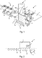
figure 1 illustrates an embodiment of a system for edge banding panels, according to the present invention; and -
figure 2 illustrates a top view of the system for the edge banding of panels offigure 1 . - In the various figures, similar parts will be indicated by the same reference numbers.
- With reference to the embodiment shown in
figures 1 and 2 , an edge banding system according to the present invention is shown, indicated as a whole with the reference letter S, which comprises a spreadingunit 1 for spreading an adhesive substance on a lateral surface or edge B of a panel P, apressing unit 3 to press an edge banding tape (not shown in the figures) onto said edge B, and aheating unit 2, interposed between said spreadingunit 1 and saidpressure 3, to heat said adhesive substance. - In addition, the edge banding system S also comprises coupling means (not shown in the figures), for coupling to the edge of a moving plane (not shown in the figures), for moving the panel P to be edge banded. Said moving plane can be for example constituted by a plane with motorized rollers or with a belt.
- As said, the spreading
unit 1 allows spreading an adhesive substance, such as glue and the like, on at least one side surface or edge B of said panel P. - More specifically, said spreading
unit 1 comprises at least oneapplication roller 10 for spreading the glue on said edge B of said panel P, while the latter moves with respect to said spreadingunit 1 in the movement direction A. - In fact, this panel P is moved at a predetermined speed by means of, for example, said sliding belt towards said spreading
unit 1 of said system S, and, therefore, towards saidapplication roller 10. - Generally, the spreading system S also comprises an applicator device (not shown in the figures) which applies the glue taken from a container on the lateral surface of said
application roller 10. - Said
application roller 10 may possibly have variable dimensions according to the dimensions of the panel P surface, on which the glue must be applied. - As can be seen from
figure 1 , said pressingunit 3 is arranged downstream said spreadingunit 1, and is configured, as said, to press an edge banding tape on said edge B of said panel P. - In particular, said pressing
unit 3 comprises at least onepressure roller 30 for exerting a pressure on the edge banding tape, so that the latter adheres to said edge B of said panel P. In the case in question, as can be seen, said pressingunit 3 comprises fourpressure rollers 30 arranged in series, so as to exert an optimal pressure of the edge banding tape on said edge B of said panel P. - The
heating unit 2 is interposed between said spreadingunit 1 and said pressingunit 3 so as to allow, as described better below, heating the glue already spread on said edge B of said panel P before thepressure unit 3 apply the edge banding tape to the same edge B. - More specifically, said
heating unit 2 faces said edge B of said panel P, and comprises a plurality ofheating elements 20, arranged so as to form a matrix ofheating elements 20. - In the embodiment described, said
heating elements 20 are IR diodes (from the English "Infrared Radiation"), intended to heat the glue spread on the edge B by irradiation. Alternatively, or in addition, said radiating elements can be LASER emitters of infrared radiation, or of electromagnetic radiation with a frequency band of the electromagnetic spectrum, possibly but not necessarily lower than that of the visible light. - However, in further embodiments, said
heating elements 20 can be different from said IR or LASER diodes such as, for example, halogen lamps. - In the aforementioned configuration, said
heating unit 2 is capable of selectively heating said glue spread on said edge B of said panel P by said spreadingunit 1. - In fact, said
heating unit 2 is capable of heating one or more portions of said edge B, on which the glue has been spread, by activating, deactivating, or partially activating one ormore heating elements 20 of saidheating elements 20 matrix. - In an embodiment of the present invention, said
heating unit 2 is capable of activating at least one row and/or at least one column of saidheating elements 20 matrix to heat the respective edge portion B located at said row and/or column of said matrix. - However, in further embodiments of the present invention, said
heating unit 2 can activate or deactivate saidheating elements 20 arranged in different positions of said array ofheating elements 20, according to the needs. - Furthermore, again to obtain selective heating of the glue applied on the edge B of the panel P, it is also possible to provide focal members, such as lenses and the like, to focus electromagnetic radiation in particular points or areas of the edge B of the panel P.
- The system S according to the present invention further comprises temperature detection means 4, and a
logic control unit 5, connected to said temperature detection means 4 and to saidheating unit 2. - Said temperature sensing means 4, such as, for example, an infrared temperature sensor, are arranged in correspondence with said edge B of said panel P and are capable of detecting temperature values of the glue spread on said edge B of said panel P.
- In particular, said temperature sensing means 4 are capable of detecting whether the temperature of said glue spread on said edge B is greater or less than a predetermined temperature threshold, or its distribution uniformity.
- Moreover, said temperature detection means 4 are further configured to transmit temperature values to said
logic control unit 5. - Said
logic control unit 5 is thus able to transmit the activation or deactivation signals to saidheating unit 2 to activate or deactivate eachheating element 20 so as to heat in a suitable way the glue applied on the edge B of the panel, and in particular, possibly, to make its temperature distribution uniform, to ensure optimal adhesion at the time of application of the edge banding tape. It should also be considered that among the information detected by thelogic control unit 5 there is also the movement speed of the panel P, as a function of which, also, each of saidheating elements 20 of saidheating unit 2 can be controlled or activated. Furthermore, saidlogic control unit 5 is further configured to receive temperature values from said temperature detection means 4. - In this way, said
logic control unit 5 is capable of monitoring the temperature of said adhesive substance spread on said edge B and consequently activate or deactivate eachheating element 20 of saidheating unit 2. - On the basis of the above, the means for detecting the
temperature 4, thelogic control unit 5, and theheating unit 2 form a temperature feedback system, which allows optimum driving of the matrix of saidheating elements 20. - The operation of the embodiment of said system S described above is as follows.
- Initially, the panel P is moved towards said spreading
unit 1. Typically, the movement of said panel P takes place by means of a conveyor belt (not shown in the figures). - Subsequently, said spreading
unit 1 spreads, by means of saidapplication roller 10, the glue on the edge B of the panel P, which moves at a predetermined speed with respect to said spreadingunit 1. - Thereafter, the temperature detection means 4 detect the temperature of said glue and transmit the value of this temperature to said
logic control unit 5. The latter, therefore, sends suitable activation or deactivation signals to activate or deactivate therespective heating elements 20 included in saidheating unit 2. - At this point, said
heating unit 2 activates or deactivates saidheating elements 20, so as to heat the respective portions of said edge B of said panel P. - Finally, said
pressing unit 3, by means of therollers 30, presses the edge banding tape on said edge B of said panel P, so as to make said tape adhere to said glue spread on said edge B. - An advantage of the system for edge banding panels according to the present invention is that of allowing the correct adhesion of the edge banding tape to the edge of the panel to be machined.
- Another advantage of the system for edge banding panels according to the present invention is that of selectively heating one or more portions of the panel to be processed.
- A further advantage of the system for edge banding panels according to the present invention is that of detecting the temperature of the glue present on the edge of the panel.
- The present invention has been described for illustrative but not limitative purposes, according to its preferred embodiments, but it is to be understood that modifications and/or changes can be introduced by those skilled in the art without departing from the relevant scope as defined in the enclosed claims.
Claims (7)
- System (S) for edge banding a panel (P), such as a panel made of wood, fiberglass, plastic and the like by means of an edge banding tape, comprising
a spreading unit (1) for coating an adhesive substance, such as glue and the like, on at least one lateral surface or edge (B) of the said panel (P), wherein said panel (P) is movable with respect to said spreading unit (1), and
a pressing unit (3), for pressing a tape on said edge (B) of said panel (P), arranged downstream of a spreading unit (1) for coating said adhesive substance,
said system (S) being characterized in that it comprises a heating unit (2), interposed between said spreading unit (1) and said pressing unit (3), wherein said heating unit (2) is configured to heat selectively said adhesive substance spread on said edge (B) of the said panel (P) by said spreading unit (1). - System (S) according to the preceding claim, characterized in that said heating unit (2) is facing said edge (B) of said panel (P) and comprises a plurality of heating elements (20).
- System (S) according to the preceding claim, characterized in that said heating elements (20) are arranged so as to form a matrix of heating elements (20).
- System (S) according to any one of the preceding claims, characterized in that it comprises
temperature sensing means (4), arranged in correspondence of said edge (B) of said panel (P) to which said adhesive substance is applied, wherein said temperature sensing means (4) are capable of detecting the temperature of said adhesive substance spread on said edge (B) of said panel (P), and
a logic control unit (5), connected to said temperature sensing means (4) and to said heating unit (2),
wherein said logic control unit (5) is configured for
receiving temperature values of said adhesive substance from said temperature sensing means (4), and
sending at least one activation or deactivation signal to said heating unit (2) to activate or deactivate one or more heating elements (20), so as to heat a respective portion of said edge (B), on which said adhesive substance is applied. - System (S) according to any one of claims 3 or 4, characterized in that said heating elements (20) are diodes or LASER.
- System (S) according to the preceding claim, characterized in that said diodes or LASER are infrared radiation.
- System (S) according to any one of claims 4-6, characterized in that said logic control unit (5) is configured to receive the movement relative speed of said panel (P) with respect to said system (S) for the edge banding of said panel (P), wherein said logic control unit (5) is configured to drive said heating unit (2) as a function of said speed.
Applications Claiming Priority (1)
| Application Number | Priority Date | Filing Date | Title |
|---|---|---|---|
| IT102019000024529A IT201900024529A1 (en) | 2019-12-18 | 2019-12-18 | System for the edging of panels. |
Publications (1)
| Publication Number | Publication Date |
|---|---|
| EP3838525A1 true EP3838525A1 (en) | 2021-06-23 |
Family
ID=70155129
Family Applications (1)
| Application Number | Title | Priority Date | Filing Date |
|---|---|---|---|
| EP20213706.3A Pending EP3838525A1 (en) | 2019-12-18 | 2020-12-14 | System for edge banding of panels |
Country Status (2)
| Country | Link |
|---|---|
| EP (1) | EP3838525A1 (en) |
| IT (1) | IT201900024529A1 (en) |
Cited By (1)
| Publication number | Priority date | Publication date | Assignee | Title |
|---|---|---|---|---|
| CN117507091A (en) * | 2023-10-30 | 2024-02-06 | 索菲亚家居股份有限公司 | Edge sealing equipment and furniture edge sealing process |
Citations (10)
| Publication number | Priority date | Publication date | Assignee | Title |
|---|---|---|---|---|
| DE7818545U1 (en) * | 1978-06-21 | 1980-03-13 | B. Raimann Gmbh, 7800 Freiburg | DEVICE FOR APPLYING GLUE |
| EP0169188A2 (en) * | 1984-06-20 | 1986-01-22 | Johann Berger | Process and apparatus for glueing rims to plate material |
| WO2001036168A1 (en) * | 1999-11-18 | 2001-05-25 | Brandt Kantentechnik Gmbh | Method and device for adhering a covering material to surfaces of plate- or strip-formed workpieces that are continually moved or arranged in a stationary manner |
| EP2902160A1 (en) * | 2014-02-04 | 2015-08-05 | BIESSE S.p.A. | Macchina per la bordatura di pannelli di legno o simili |
| DE102016213216A1 (en) * | 2015-07-21 | 2017-01-26 | Biesse S.P.A. | Machine for edge banding of wood or similar boards |
| EP2966936B1 (en) * | 2014-07-11 | 2018-02-28 | HOMAG GmbH | Device for heating a functional layer |
| EP2952307B1 (en) * | 2014-06-05 | 2018-04-25 | IMA Klessmann GmbH | Device and method for applying an edge strip to a narrow edge of a workpiece |
| EP3461608A1 (en) * | 2017-09-29 | 2019-04-03 | HOMAG GmbH | Coating device and coating method |
| EP3517264A1 (en) * | 2018-01-24 | 2019-07-31 | BIESSE S.p.A. | Edgebanding assembly and method for edgebanding panels of wood or the like |
| EP3533573B1 (en) * | 2018-03-01 | 2020-09-09 | BIESSE S.p.A. | A machine to process panels made of wood or the like |
-
2019
- 2019-12-18 IT IT102019000024529A patent/IT201900024529A1/en unknown
-
2020
- 2020-12-14 EP EP20213706.3A patent/EP3838525A1/en active Pending
Patent Citations (10)
| Publication number | Priority date | Publication date | Assignee | Title |
|---|---|---|---|---|
| DE7818545U1 (en) * | 1978-06-21 | 1980-03-13 | B. Raimann Gmbh, 7800 Freiburg | DEVICE FOR APPLYING GLUE |
| EP0169188A2 (en) * | 1984-06-20 | 1986-01-22 | Johann Berger | Process and apparatus for glueing rims to plate material |
| WO2001036168A1 (en) * | 1999-11-18 | 2001-05-25 | Brandt Kantentechnik Gmbh | Method and device for adhering a covering material to surfaces of plate- or strip-formed workpieces that are continually moved or arranged in a stationary manner |
| EP2902160A1 (en) * | 2014-02-04 | 2015-08-05 | BIESSE S.p.A. | Macchina per la bordatura di pannelli di legno o simili |
| EP2952307B1 (en) * | 2014-06-05 | 2018-04-25 | IMA Klessmann GmbH | Device and method for applying an edge strip to a narrow edge of a workpiece |
| EP2966936B1 (en) * | 2014-07-11 | 2018-02-28 | HOMAG GmbH | Device for heating a functional layer |
| DE102016213216A1 (en) * | 2015-07-21 | 2017-01-26 | Biesse S.P.A. | Machine for edge banding of wood or similar boards |
| EP3461608A1 (en) * | 2017-09-29 | 2019-04-03 | HOMAG GmbH | Coating device and coating method |
| EP3517264A1 (en) * | 2018-01-24 | 2019-07-31 | BIESSE S.p.A. | Edgebanding assembly and method for edgebanding panels of wood or the like |
| EP3533573B1 (en) * | 2018-03-01 | 2020-09-09 | BIESSE S.p.A. | A machine to process panels made of wood or the like |
Cited By (1)
| Publication number | Priority date | Publication date | Assignee | Title |
|---|---|---|---|---|
| CN117507091A (en) * | 2023-10-30 | 2024-02-06 | 索菲亚家居股份有限公司 | Edge sealing equipment and furniture edge sealing process |
Also Published As
| Publication number | Publication date |
|---|---|
| IT201900024529A1 (en) | 2021-06-18 |
Similar Documents
| Publication | Publication Date | Title |
|---|---|---|
| US10967622B2 (en) | Coating device and coating method | |
| US20120073748A1 (en) | Device for Coating a Workpiece | |
| US20180222141A1 (en) | Plastic Bag Making Apparatus | |
| US4069081A (en) | Method for protective film lamination with curl control | |
| CA2475557A1 (en) | Method and apparatus for processing sealant of an insulating glass unit | |
| AU2018269298A1 (en) | Absorbent article with channels and method for manufacturing thereof | |
| US7767050B2 (en) | Laminating roller assembly, credential substrate laminator and method of laminating a credential substrate | |
| EP3372364A1 (en) | Method and apparatus for adhesive activation | |
| BRPI0609619A2 (en) | apparatus and process for coating a metal backing material | |
| CN206363038U (en) | It is continuously asynchronous to be posted equipment | |
| WO2015096623A1 (en) | Control system for multi-chain synchronous operation and method for synchronous operation thereof | |
| GB1055564A (en) | Improvements in or relating to continuous presses | |
| US20140202384A1 (en) | Glue spreading system | |
| DE102013102984A1 (en) | Foil stamping device | |
| US20120037292A1 (en) | Flexible film application for decorative coatings | |
| EP1002642B1 (en) | Laminator | |
| KR20210113218A (en) | Method and device for adhesive bonding substrates in film form and composite obtained thereby | |
| US5453128A (en) | Coating system for running webs of paper or cardboard | |
| EP2990171B1 (en) | Method and device for localised thermal-melting | |
| US20170312992A1 (en) | Method and apparatus for applying a heat-activated double-sided adhesive tape to a support | |
| CA2245052A1 (en) | Method and device for monitoring the thickness of continuously conveyed flat objects | |
| EP0501030B1 (en) | Material winding method and apparatus of tire molding machine | |
| GB1573158A (en) | Method for protective film lamination with curl control | |
| KR101701775B1 (en) | A film attaching apparatus for ship | |
| JPS5927205A (en) | Method for detecting applied film |
Legal Events
| Date | Code | Title | Description |
|---|---|---|---|
| PUAI | Public reference made under article 153(3) epc to a published international application that has entered the european phase |
Free format text: ORIGINAL CODE: 0009012 |
|
| STAA | Information on the status of an ep patent application or granted ep patent |
Free format text: STATUS: THE APPLICATION HAS BEEN PUBLISHED |
|
| AK | Designated contracting states |
Kind code of ref document: A1 Designated state(s): AL AT BE BG CH CY CZ DE DK EE ES FI FR GB GR HR HU IE IS IT LI LT LU LV MC MK MT NL NO PL PT RO RS SE SI SK SM TR |
|
| STAA | Information on the status of an ep patent application or granted ep patent |
Free format text: STATUS: REQUEST FOR EXAMINATION WAS MADE |
|
| 17P | Request for examination filed |
Effective date: 20211119 |
|
| RBV | Designated contracting states (corrected) |
Designated state(s): AL AT BE BG CH CY CZ DE DK EE ES FI FR GB GR HR HU IE IS IT LI LT LU LV MC MK MT NL NO PL PT RO RS SE SI SK SM TR |
|
| STAA | Information on the status of an ep patent application or granted ep patent |
Free format text: STATUS: EXAMINATION IS IN PROGRESS |
|
| 17Q | First examination report despatched |
Effective date: 20221209 |
|
| P01 | Opt-out of the competence of the unified patent court (upc) registered |
Effective date: 20230518 |