EP3838494A1 - Appareil de travail - Google Patents
Appareil de travail Download PDFInfo
- Publication number
- EP3838494A1 EP3838494A1 EP19218909.0A EP19218909A EP3838494A1 EP 3838494 A1 EP3838494 A1 EP 3838494A1 EP 19218909 A EP19218909 A EP 19218909A EP 3838494 A1 EP3838494 A1 EP 3838494A1
- Authority
- EP
- European Patent Office
- Prior art keywords
- piston
- stator
- working
- coil
- capacitor
- Prior art date
- Legal status (The legal status is an assumption and is not a legal conclusion. Google has not performed a legal analysis and makes no representation as to the accuracy of the status listed.)
- Withdrawn
Links
Images


Classifications
-
- B—PERFORMING OPERATIONS; TRANSPORTING
- B25—HAND TOOLS; PORTABLE POWER-DRIVEN TOOLS; MANIPULATORS
- B25C—HAND-HELD NAILING OR STAPLING TOOLS; MANUALLY OPERATED PORTABLE STAPLING TOOLS
- B25C1/00—Hand-held nailing tools; Nail feeding devices
- B25C1/06—Hand-held nailing tools; Nail feeding devices operated by electric power
-
- H—ELECTRICITY
- H02—GENERATION; CONVERSION OR DISTRIBUTION OF ELECTRIC POWER
- H02K—DYNAMO-ELECTRIC MACHINES
- H02K11/00—Structural association of dynamo-electric machines with electric components or with devices for shielding, monitoring or protection
- H02K11/0094—Structural association with other electrical or electronic devices
-
- H—ELECTRICITY
- H02—GENERATION; CONVERSION OR DISTRIBUTION OF ELECTRIC POWER
- H02K—DYNAMO-ELECTRIC MACHINES
- H02K33/00—Motors with reciprocating, oscillating or vibrating magnet, armature or coil system
- H02K33/02—Motors with reciprocating, oscillating or vibrating magnet, armature or coil system with armatures moved one way by energisation of a single coil system and returned by mechanical force, e.g. by springs
-
- H—ELECTRICITY
- H02—GENERATION; CONVERSION OR DISTRIBUTION OF ELECTRIC POWER
- H02K—DYNAMO-ELECTRIC MACHINES
- H02K33/00—Motors with reciprocating, oscillating or vibrating magnet, armature or coil system
- H02K33/12—Motors with reciprocating, oscillating or vibrating magnet, armature or coil system with armatures moving in alternate directions by alternate energisation of two coil systems
-
- H—ELECTRICITY
- H02—GENERATION; CONVERSION OR DISTRIBUTION OF ELECTRIC POWER
- H02P—CONTROL OR REGULATION OF ELECTRIC MOTORS, ELECTRIC GENERATORS OR DYNAMO-ELECTRIC CONVERTERS; CONTROLLING TRANSFORMERS, REACTORS OR CHOKE COILS
- H02P1/00—Arrangements for starting electric motors or dynamo-electric converters
- H02P1/16—Arrangements for starting electric motors or dynamo-electric converters for starting dynamo-electric motors or dynamo-electric converters
- H02P1/42—Arrangements for starting electric motors or dynamo-electric converters for starting dynamo-electric motors or dynamo-electric converters for starting an individual single-phase induction motor
- H02P1/44—Arrangements for starting electric motors or dynamo-electric converters for starting dynamo-electric motors or dynamo-electric converters for starting an individual single-phase induction motor by phase-splitting with a capacitor
- H02P1/445—Arrangements for starting electric motors or dynamo-electric converters for starting dynamo-electric motors or dynamo-electric converters for starting an individual single-phase induction motor by phase-splitting with a capacitor by using additional capacitors switched at start up
Definitions
- the present invention relates to a tool, such as a setting tool for driving fastening elements into a substrate.
- Tools of this type often have a working piston which is intended to move along a working axis.
- the working piston is driven by a drive which accelerates the working piston.
- the WO 2018/104406 A1 describes a drive which has an electrical capacitor, a squirrel-cage rotor arranged on the working piston and an excitation coil through which current flows when the capacitor is rapidly discharged and generates a magnetic field in order to accelerate the working piston.
- Setting tools usually have a receptacle for a fastening element, from which a fastening element received therein is conveyed into the ground along a working axis.
- the working element is driven by the drive along the working axis towards the fastening element.
- a setting tool with a drive which has an electrical capacitor and a coil.
- the object of the present invention is to provide a setting tool of the aforementioned type in which a high degree of efficiency and / or a good setting quality is guaranteed.
- the object is achieved with a preferably hand-held tool for working a subsurface, having a stator and a working piston which is provided to move relative to the stator along a working axis, furthermore having a drive which is provided for moving along the working piston the To drive the working axis onto the ground, the drive having a capacitor and a piston coil arranged on the working piston, the piston coil being electrically connectable to the capacitor in order to be flowed through with current in the event of a rapid discharge of the electric piston coil capacitor and to generate a magnetic field which accelerates the working piston relative to the stator, the drive having a diode which is arranged on the working piston and is electrically connected to the piston coil.
- An advantageous embodiment is characterized in that the drive has a circuit comprising the diode, by means of which the rapid discharge is triggered and / or the piston coil is electrically connected to the piston coil capacitor.
- An advantageous embodiment is characterized in that the diode is electrically connected in parallel with the piston coil.
- the diode is preferably designed as a freewheeling diode for rapid discharge of the capacitor.
- An advantageous embodiment is characterized in that the drive has a stator coil which is arranged on the stator and which can be electrically connected to the capacitor in order to have current flowing through it in the event of a rapid discharge of the capacitor and to generate a magnetic field which moves the working piston relative to the stator accelerated.
- the piston coil and the stator coil are preferably connected electrically in series with one another.
- stator has two electrical stator contacts and the working piston has two electrical piston contacts each sliding on one of the electrical stator contacts over a sliding length in order to electrically connect the piston coil to the electrical piston coil capacitor.
- the electrical stator contacts each have a contact bar and the electrical piston contacts each have a contact brush or a slip ring, or vice versa.
- the sliding length is likewise preferably shorter than a movement path of the working piston along the working axis.
- stator has a stator frame made of a soft magnetic material which surrounds the stator coil.
- working piston has a piston frame made of a soft magnetic material which surrounds the piston coil.
- the working device is designed as a setting device for driving fastening elements into a substrate, having a receptacle which is provided for a fastening element receive, wherein the working piston is provided for conveying a fastening element received in the receptacle along the working axis into the ground, and wherein the drive is provided for driving the working piston along the working axis onto the fastening element.
- a capacitor in the sense of the invention is to be understood as an electrical component which stores electrical charge and the associated energy in an electrical field.
- a capacitor has two electrically conductive electrodes, between which the electric field builds up when the electrodes are electrically charged differently.
- a fastening element in the context of the invention is to be understood as meaning, for example, a nail, a pin, a clamp, a clip, a bolt, in particular a threaded bolt or the like.
- a soft magnetic material in the context of the invention is to be understood as a material which has a high magnetic saturation flux density and in particular a small coercive field strength and thus strengthens a magnetic field penetrating the material.
- the soft magnetic material of the stator frame and / or the piston frame has a saturation flux density of at least 1.0 T, preferably at least 1.3 T, particularly preferably at least 1.5 T.
- An electrically conductive material in the context of the invention is to be understood as a material which has a high specific electrical conductivity, so that a magnetic field penetrating the material generates eddy currents in the material.
- a soft magnetic and / or electrically conductive material preferably consists of a ferromagnetic material, particularly preferably a ferromagnetic metal, for example iron, cobalt, nickel, or an alloy with one or more ferromagnetic metals as the main component.
- a working device 10 for processing a subsurface is shown in a longitudinal section, which is designed as a hand-operated setting device for driving fastening elements into the subsoil.
- the work device 10 has a receptacle 20 designed as a bolt guide, in which a fastening element 30 designed as a nail is received in order to be driven into the ground along a work axis A (in Fig. 1 to the left).
- the working device 10 For feeding fastening elements to the receptacle, the working device 10 comprises a magazine 40 in which the fastening elements are received individually or in the form of a fastening element strip 50 and are gradually transported into the receptacle 20.
- the magazine 40 has a spring-loaded feed element which is not designated in any more detail.
- the working device 10 has a working piston 60 which comprises a piston body 70 and a piston rod 80.
- the working piston 60 is provided for conveying the fastening element 30 out of the receptacle 20 along the working axis A into the ground.
- the working piston 60 with its piston body 70 is guided in a guide cylinder 95 along the working axis A.
- the working piston is guided along the working axis by two, three or more guide elements, for example guide rods.
- the working piston 60 is in turn driven by a drive 65 which comprises a switching circuit 200 and a capacitor 300.
- the circuit 200 is provided to bring about a rapid electrical discharge of the previously charged capacitor 300 and to feed the discharge current flowing in the process to the drive 65.
- the working device 10 further comprises a housing 110 in which the drive 65 is accommodated, a handle 120 with an actuating element 130 designed as a trigger, an electrical energy store 140 designed as an accumulator, a control unit 150, a trigger switch 160, a pressure switch 170, and an on the drive 65 arranged temperature sensor 180 and electrical connecting lines 141, 161, 171, 181, 201, 301, which the control unit 150 with the electrical energy storage 140, the trigger switch 160, the pressure switch 170, the temperature sensor 180, the circuit 200 and the capacitor 300 connect.
- the working device 10 is supplied with electrical energy by means of a power cable instead of the electrical energy store 140 or in addition to the electrical energy store 140.
- the control unit comprises electronic components, preferably interconnected on a circuit board to form one or more control circuits, in particular one or more microprocessors.
- the control unit 150 initiates a capacitor charging process in which electrical energy is conducted by means of the connecting line 141 from the electrical energy store 140 to the control unit 150 and by means of the connecting lines 301 from the control unit 150 to the capacitor 300 to electrically connect the capacitor 300 to charge.
- the control unit 150 comprises a switching converter, not shown in more detail, which converts the electrical current from the electrical energy store 140 into a suitable charging current for the capacitor 300.
- the control unit initiates the capacitor charging process as soon as the implement is switched on or when the implement is lifted from the ground or when a previous driving process is terminated.
- the actuating element 130 When the actuating element 130 is actuated when the implement 10 is ready to be set, for example by pulling with the index finger of the hand that grips the handle 120, the actuating element 130 actuates the trigger switch 160, which thereby transmits a trigger signal to the control unit 150 via the connecting line 161. Triggered by this, the control unit 150 initiates a capacitor discharge process, in which electrical energy stored in the capacitor 300 is conducted by means of the switching circuit 200 from the capacitor 300 to the drive 65 by electrically discharging the capacitor 300.
- the schematically illustrated circuit 200 comprises two discharge lines 210, 220 which connect the capacitor 300 to the drive 65 and of which at least one discharge line 210 is interrupted by a normally open discharge switch 230.
- the circuit 200 forms an electrical oscillating circuit with the drive 65 and the capacitor 300 under certain circumstances. Swinging this resonant circuit back and forth and / or negative charging of the capacitor 300 may have a negative effect on the efficiency of the drive 65 but prevent themselves with the help of a freewheeling diode 240.
- the discharge lines 210, 220 are electrically connected to an electrode 310, 320 of the capacitor 300 arranged on a carrier film 330 by means of electrical contacts 370, 380 of the capacitor 300 arranged on an end face 360 of the capacitor 300 facing the receptacle 20, for example by soldering, welding , Screwing, clamping or form fit.
- the discharge switch 230 is preferably suitable for switching a discharge current with a high current intensity and is designed, for example, as a thyristor.
- the discharge lines 210, 220 are at a small distance from one another so that a parasitic magnetic field induced by them is as small as possible.
- the discharge lines 210, 220 are combined to form a bus bar and are held together with a suitable means, for example a holder or a clamp.
- a suitable means for example a holder or a clamp.
- the freewheeling diode is connected electrically in parallel with the discharge switch.
- no freewheeling diode is provided in the circuit.
- the control unit 150 closes the discharge switch 230 by means of the connecting line 201, whereby a high-intensity discharge current of the capacitor 300 flows through the drive 65, which drives the working piston 60 towards the receptacle 20 and the fastening element 30 received therein.
- the piston rod 80 of the working piston 60 hits a head of the fastening element 30, which is not designated in any more detail, the fastening element 30 is driven into the ground by the working piston 60.
- a braking element 85 made of a resilient and / or damping material, for example rubber or an elastomer, in that the working piston 60 moves with its piston body 70 against the braking element 85 and is braked by it to a standstill . Thereafter, the working piston 60 is returned to the ready-to-set position by a return device (not shown).
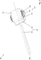
- the drive / working piston unit 400 comprises a partly shown drive 410, a working piston 420 and a stator 430.
- the working piston 420 has a piston body 421 and a piston rod 422 and is intended to be oriented relative to the stator 430 along a working axis 401 move.
- the drive 410 is provided to drive the working piston 420 along the working axis 401.
- the drive 410 comprises a capacitor (not shown) and one arranged on the working piston 420 Piston coil 440.
- the piston coil 440 can be electrically connected to the capacitor so that current flows through it in the event of a rapid discharge of the capacitor and to generate a magnetic field which causes a repulsive force between the piston coil 440 and the stator 430 and the working piston 420 relative to the Stator 430 accelerates.
- the drive 410 comprises a first stator coil 450 arranged on the stator 430 and a second stator coil 455 arranged on the stator 430.
- the stator coils 450, 455 can be electrically connected to the capacitor so that current flows through them in the event of a rapid discharge of the capacitor to generate a magnetic field, which causes a repulsive force between the stator coils 450, 455 and the working piston 420 and accelerates the working piston 420 away from the stator 430.
- the repulsive force between the stator coil 450 and the working piston 420 is brought about, for example, in that the magnetic field generated by the stator coils 450, 455 is opposite to the magnetic field generated by the piston coil 440.
- the first stator coil 450 and the second stator coil 455 are subjected to one another in the same direction, while the piston coil 440 is subjected to electrical current in opposite directions and at the same time, in that the capacitor is discharged.
- the stator coils 450, 455 are arranged opposite one another on two sides of the working axis 401 and the piston coil 440 is arranged between the stator coils 450, 455 on the working axis 401.
- the piston coil 440 and the stator coils 450, 455 each have a piston coil axis and a stator coil axis, respectively, which are inclined perpendicularly relative to the working axis 401 and are oriented parallel to one another.
- a drive 510 of an implement for example the one in Fig. 1 working device 10 shown.
- the drive 510 is shown cut open along a working axis 501 and is provided for driving a working piston 520 with a piston body 521 and a piston rod 522 along the working axis 501 and moving it relative to a stator 530.
- the drive 510 comprises a capacitor 560, a switching circuit 570 with a switch 571 and a current control element 572 configured as a diode, in particular a freewheeling diode, a piston coil 540 arranged on the working piston 520, a first stator coil 550 arranged on the stator 530 and one on the stator 530 arranged second stator coil 550.
- the piston coil 540 and the stator coils 550, 555 can be electrically connected to the capacitor 560 in order to have a current flowing through them in the event of a rapid discharge of the capacitor 560.
- a current flow through the piston coil 540 generates a first magnetic field, while a current flow through the stator coils 550, 555 generates a second magnetic field.
- One electrode of the capacitor 560 is electrically connected to an input of the switch 571 and can be charged with respect to a counter electrode of the capacitor 560, which is electrically connected to a ground potential (not shown), for example the negative pole of an electrical accumulator or a battery.
- An output of the switch 571 is electrically connected to an input of the first stator coil 550, preferably hard-wired.
- An output of the first stator coil 550 is electrically connected, preferably hard-wired, to a first electrical stator contact 531 embodied as a contact brush and which the stator 530 has.
- An input of the piston coil 540 is electrically connected, preferably permanently wired, to a first piston contact 541 designed as a contact rail and which the working piston 520 has.
- the first piston contact 541 slides in an electrically conductive manner along the first stator contact 531 when the working piston 520 moves along the working axis 501.
- a first spring loads the first stator contact 531 towards the first piston contact 541.
- a spring additionally or alternatively loads the first piston contact towards the first stator contact.
- An output of the piston coil 540 is electrically connected, preferably permanently wired, to a second piston contact 542 which is designed as a contact bar and which the working piston 520 has.
- the second piston contact 542 slides in an electrically conductive manner along a second stator contact 532 when the working piston 520 moves along the working axis 501.
- the stator 530 has the second stator contact 532, which is designed as a contact brush and is electrically connected to an input of the second stator coil 555.
- an output of the second stator coil 555 is electrically connected to the ground potential.
- a second spring not shown, loads the second stator contact 532 towards the second piston contact 542.
- a spring additionally or alternatively loads the second piston contact towards the second stator contact.
- the piston contacts 541, 542 do not necessarily contact the stator contacts 531, 532 during the entire movement of the working piston. In some applications, contacting during the first 0.5 ms to 1 ms, in particular during the first 0.6 ms, is sufficient.
- the piston contacts 541, 542 have a length in the direction of the working axis 501, which for some areas of application is approximately 10 mm to 30 mm.
- the piston contacts 541, 542 are rigidly connected to the rest of the working piston 520 and move with the rest of the working piston 520.
- the first and / or the second stator contact is a slip ring educated.
- the first and / or the second stator contact is designed as a contact bar and the first or the second piston contact is designed as a contact brush or slip ring.
- the second piston contact 542 and the second stator contact 532 are arranged with respect to the coils 540, 550, 555 radially inside the stator coils 550, 555 and the piston coil 540.
- the rapid discharge of the capacitor 560 via the piston coil 540 and the stator coil 550 can be triggered by means of the circuit 570 in that the switch 571 is closed when the capacitor 560 is electrically charged and the piston coil 540 and the stator coils 550, 555 are electrically connected to the capacitor 560.
- the electrical current then flows from the capacitor 560 through the switch 571, through the first stator coil 550, through the first stator contact 531 and the first piston contact 541, through the piston coil 540, through the second piston contact 542 and the second stator contact 532 and finally through the second stator coil 555 to capacitor 560 or to ground potential.
- the piston coil 540 and the stator coil 550 each have a piston coil axis and a stator coil axis, which are oriented perpendicular to the working axis 501 and parallel to one another.
- the piston coil 540 and the stator coils 550, 555 are wound in the same direction and the electric current flows through them in opposite directions, so that the first magnetic field generated by the piston coil 540 and the second magnetic field generated by the stator coils 550, 555 are opposite to one another.
- the coils are wound in opposite directions and the electric current flows through them in the same direction.
- the piston coil 540 and the stator coils 550, 555 are electrically connected in series with one another, that is, an electric current flows through them at the same time, a current intensity of the current flowing through the coils 540, 550, 555 being the same for the piston coil 540 and the stator coil 550.
- the piston coil 540 and the stator coils 550, 555 each have the same number of coil turns, so that the magnetic fields generated by the coils 540, 550, 555 are equally strong.
- the working piston 520 has a piston frame 525, which preferably consists of a soft magnetic material, such as iron or an alloy thereof, for example steel.
- the piston frame 525 surrounds the piston coil 540.
- the piston body 521 is preferably made of the soft magnetic material and particularly preferably forms the piston frame.
- the piston rod 522 also preferably consists of the soft magnetic material and is particularly preferably connected in one piece to the piston body 521, which may increase the rigidity and / or mechanical robustness of the working piston 520.
- the stator 530 has a stator frame 535, which preferably consists of a soft magnetic material, such as iron or an alloy thereof, for example steel.
- the stator frame 535 surrounds the stator coils 550, 555.
- the second magnetic field generated by the stator coils 550, 555 is intensified in the area of the piston coil 540 and the repulsive force between the stator 530 and the working piston 520 is increased.
- the piston coil axis is arranged offset relative to the stator coil axes in the direction of the working axis 501. This improves repulsion in the direction of the working axis 501.
- the working device has a guide 599, for example designed as a guide rail.
- the drive has a diode arranged on the working piston, which is electrically connected to the piston coil.
- the drive has a circuit comprising the diode, by means of which the rapid discharge is triggered and / or the piston coil is electrically connected to the capacitor.
- Fig. 5 is an electrical circuit diagram of the in Fig. 4 Drive 510 shown.
- the drive 510 includes a first diode 591 assigned to the first stator coil 550, a second diode 592 assigned to the second stator coil and one assigned to the piston coil 541 Piston diode 593.
- the piston diode 593 is an exemplary embodiment of a current control element for controlling the electrical current flowing through the piston coil 541.
- the coils 541, 550, 555 form an oscillating circuit with the capacitor 560.
- the current control element 593 now serves to suppress this oscillating circuit from oscillating back after the capacitor 560 has discharged.
- the in Fig. 4 Piston contacts shown de-energized so that the risk of electrical flashovers between the piston contacts and the stator contacts is reduced.
- This can be used to shorten the contact rails involved, in particular to a sliding length that is shorter than a movement path of the working piston 520 along the working axis.
- This is made possible by an arrangement, in particular fastening of the flow control element 593 on the working piston 520.
- the diode 593 is electrically connected in parallel to the piston coil 541.
Priority Applications (4)
| Application Number | Priority Date | Filing Date | Title |
|---|---|---|---|
| EP19218909.0A EP3838494A1 (fr) | 2019-12-20 | 2019-12-20 | Appareil de travail |
| US17/783,490 US20230007855A1 (en) | 2019-12-20 | 2020-12-09 | Working tool |
| PCT/EP2020/085306 WO2021122230A1 (fr) | 2019-12-20 | 2020-12-09 | Outil de travail |
| EP20817433.4A EP4076850B1 (fr) | 2019-12-20 | 2020-12-09 | Appareil de travail |
Applications Claiming Priority (1)
| Application Number | Priority Date | Filing Date | Title |
|---|---|---|---|
| EP19218909.0A EP3838494A1 (fr) | 2019-12-20 | 2019-12-20 | Appareil de travail |
Publications (1)
| Publication Number | Publication Date |
|---|---|
| EP3838494A1 true EP3838494A1 (fr) | 2021-06-23 |
Family
ID=69005350
Family Applications (2)
| Application Number | Title | Priority Date | Filing Date |
|---|---|---|---|
| EP19218909.0A Withdrawn EP3838494A1 (fr) | 2019-12-20 | 2019-12-20 | Appareil de travail |
| EP20817433.4A Active EP4076850B1 (fr) | 2019-12-20 | 2020-12-09 | Appareil de travail |
Family Applications After (1)
| Application Number | Title | Priority Date | Filing Date |
|---|---|---|---|
| EP20817433.4A Active EP4076850B1 (fr) | 2019-12-20 | 2020-12-09 | Appareil de travail |
Country Status (3)
| Country | Link |
|---|---|
| US (1) | US20230007855A1 (fr) |
| EP (2) | EP3838494A1 (fr) |
| WO (1) | WO2021122230A1 (fr) |
Families Citing this family (1)
| Publication number | Priority date | Publication date | Assignee | Title |
|---|---|---|---|---|
| WO2023285307A1 (fr) | 2021-07-10 | 2023-01-19 | Rhefor Gbr | Outil de pose |
Citations (4)
| Publication number | Priority date | Publication date | Assignee | Title |
|---|---|---|---|---|
| US20030183670A1 (en) * | 2000-08-25 | 2003-10-02 | Barber John P. | Impact device |
| WO2018104406A1 (fr) | 2016-12-06 | 2018-06-14 | Hilti Aktiengesellschaft | Entraînement électrodynamique |
| WO2019211264A1 (fr) * | 2018-05-01 | 2019-11-07 | Rhefor Gbr | Cloueuse manuelle et entraînement |
| WO2019233841A1 (fr) * | 2018-06-06 | 2019-12-12 | Hilti Aktiengesellschaft | Dispositif de pose |
Family Cites Families (1)
| Publication number | Priority date | Publication date | Assignee | Title |
|---|---|---|---|---|
| EP3578309A1 (fr) * | 2018-06-06 | 2019-12-11 | HILTI Aktiengesellschaft | Appareil de pose |
-
2019
- 2019-12-20 EP EP19218909.0A patent/EP3838494A1/fr not_active Withdrawn
-
2020
- 2020-12-09 US US17/783,490 patent/US20230007855A1/en active Pending
- 2020-12-09 EP EP20817433.4A patent/EP4076850B1/fr active Active
- 2020-12-09 WO PCT/EP2020/085306 patent/WO2021122230A1/fr unknown
Patent Citations (5)
| Publication number | Priority date | Publication date | Assignee | Title |
|---|---|---|---|---|
| US20030183670A1 (en) * | 2000-08-25 | 2003-10-02 | Barber John P. | Impact device |
| US6830173B2 (en) | 2000-08-25 | 2004-12-14 | Senco Products, Inc. | Impact device |
| WO2018104406A1 (fr) | 2016-12-06 | 2018-06-14 | Hilti Aktiengesellschaft | Entraînement électrodynamique |
| WO2019211264A1 (fr) * | 2018-05-01 | 2019-11-07 | Rhefor Gbr | Cloueuse manuelle et entraînement |
| WO2019233841A1 (fr) * | 2018-06-06 | 2019-12-12 | Hilti Aktiengesellschaft | Dispositif de pose |
Also Published As
| Publication number | Publication date |
|---|---|
| EP4076850C0 (fr) | 2024-02-21 |
| US20230007855A1 (en) | 2023-01-12 |
| EP4076850B1 (fr) | 2024-02-21 |
| WO2021122230A1 (fr) | 2021-06-24 |
| EP4076850A1 (fr) | 2022-10-26 |
Similar Documents
| Publication | Publication Date | Title |
|---|---|---|
| EP4076853A1 (fr) | Outil de travail | |
| WO2021122270A1 (fr) | Outil de travail | |
| EP3578309A1 (fr) | Appareil de pose | |
| EP3801989B1 (fr) | Appareil de pose | |
| EP3578306A1 (fr) | Appareil de pose | |
| EP3801993B1 (fr) | Appareil de pose | |
| EP4076849B1 (fr) | Appareil de travail | |
| WO2021122294A1 (fr) | Outil de travail | |
| EP3578312A1 (fr) | Appareil de pose | |
| EP3993954A1 (fr) | Appareil de travail | |
| EP3578315A1 (fr) | Appareil de fixation | |
| EP3801997A1 (fr) | Appareil de pose | |
| EP3801996A1 (fr) | Appareil de pose | |
| EP3578311A1 (fr) | Appareil de pose | |
| EP4076850B1 (fr) | Appareil de travail | |
| EP4076855B1 (fr) | Appareil de travail | |
| EP4076854B1 (fr) | Appareil de travail | |
| EP3578310A1 (fr) | Outil de fixation | |
| DE2537815C2 (de) | Verfahren und Vorrichtung zum Einführen eines Bolzens mit Preßsitz in eine Bohrung |
Legal Events
| Date | Code | Title | Description |
|---|---|---|---|
| PUAI | Public reference made under article 153(3) epc to a published international application that has entered the european phase |
Free format text: ORIGINAL CODE: 0009012 |
|
| STAA | Information on the status of an ep patent application or granted ep patent |
Free format text: STATUS: THE APPLICATION HAS BEEN PUBLISHED |
|
| AK | Designated contracting states |
Kind code of ref document: A1 Designated state(s): AL AT BE BG CH CY CZ DE DK EE ES FI FR GB GR HR HU IE IS IT LI LT LU LV MC MK MT NL NO PL PT RO RS SE SI SK SM TR |
|
| STAA | Information on the status of an ep patent application or granted ep patent |
Free format text: STATUS: THE APPLICATION IS DEEMED TO BE WITHDRAWN |
|
| 18D | Application deemed to be withdrawn |
Effective date: 20211224 |