EP3838443A1 - Friction material production device and friction material production method - Google Patents
Friction material production device and friction material production method Download PDFInfo
- Publication number
- EP3838443A1 EP3838443A1 EP19850707.1A EP19850707A EP3838443A1 EP 3838443 A1 EP3838443 A1 EP 3838443A1 EP 19850707 A EP19850707 A EP 19850707A EP 3838443 A1 EP3838443 A1 EP 3838443A1
- Authority
- EP
- European Patent Office
- Prior art keywords
- jig
- friction material
- stack
- material manufacturing
- manufacturing apparatus
- Prior art date
- Legal status (The legal status is an assumption and is not a legal conclusion. Google has not performed a legal analysis and makes no representation as to the accuracy of the status listed.)
- Granted
Links
Images



Classifications
-
- B—PERFORMING OPERATIONS; TRANSPORTING
- B22—CASTING; POWDER METALLURGY
- B22F—WORKING METALLIC POWDER; MANUFACTURE OF ARTICLES FROM METALLIC POWDER; MAKING METALLIC POWDER; APPARATUS OR DEVICES SPECIALLY ADAPTED FOR METALLIC POWDER
- B22F3/00—Manufacture of workpieces or articles from metallic powder characterised by the manner of compacting or sintering; Apparatus specially adapted therefor ; Presses and furnaces
- B22F3/003—Apparatus, e.g. furnaces
-
- B—PERFORMING OPERATIONS; TRANSPORTING
- B22—CASTING; POWDER METALLURGY
- B22F—WORKING METALLIC POWDER; MANUFACTURE OF ARTICLES FROM METALLIC POWDER; MAKING METALLIC POWDER; APPARATUS OR DEVICES SPECIALLY ADAPTED FOR METALLIC POWDER
- B22F3/00—Manufacture of workpieces or articles from metallic powder characterised by the manner of compacting or sintering; Apparatus specially adapted therefor ; Presses and furnaces
- B22F3/12—Both compacting and sintering
- B22F3/16—Both compacting and sintering in successive or repeated steps
-
- B—PERFORMING OPERATIONS; TRANSPORTING
- B22—CASTING; POWDER METALLURGY
- B22F—WORKING METALLIC POWDER; MANUFACTURE OF ARTICLES FROM METALLIC POWDER; MAKING METALLIC POWDER; APPARATUS OR DEVICES SPECIALLY ADAPTED FOR METALLIC POWDER
- B22F3/00—Manufacture of workpieces or articles from metallic powder characterised by the manner of compacting or sintering; Apparatus specially adapted therefor ; Presses and furnaces
- B22F3/02—Compacting only
- B22F2003/023—Lubricant mixed with the metal powder
-
- B—PERFORMING OPERATIONS; TRANSPORTING
- B22—CASTING; POWDER METALLURGY
- B22F—WORKING METALLIC POWDER; MANUFACTURE OF ARTICLES FROM METALLIC POWDER; MAKING METALLIC POWDER; APPARATUS OR DEVICES SPECIALLY ADAPTED FOR METALLIC POWDER
- B22F2998/00—Supplementary information concerning processes or compositions relating to powder metallurgy
- B22F2998/10—Processes characterised by the sequence of their steps
-
- B—PERFORMING OPERATIONS; TRANSPORTING
- B22—CASTING; POWDER METALLURGY
- B22F—WORKING METALLIC POWDER; MANUFACTURE OF ARTICLES FROM METALLIC POWDER; MAKING METALLIC POWDER; APPARATUS OR DEVICES SPECIALLY ADAPTED FOR METALLIC POWDER
- B22F2999/00—Aspects linked to processes or compositions used in powder metallurgy
Definitions
- the present application discloses a friction material manufacturing apparatus and a friction material manufacturing method.
- Brakes used in vehicles and other various machines are usually provided with friction materials.
- the friction material is a member that converts kinetic energy into thermal energy, and thus is required to exert a predetermined braking force even at a high temperature. Therefore, in order to exert the predetermined braking force even when the friction material is used in a high-temperature state, various measures for shaping the friction material at an appropriate temperature are made in a manufacturing line of the friction material (see Patent Literatures 1 to 3).
- An object of the present invention is to enable efficient manufacture of a friction material.
- a stack of workpieces which are preforms of friction materials, is clamped by a jig, and in this state, the stack is heated with infrared rays from a lateral side with respect to a stacking direction.
- the present invention is a friction material manufacturing apparatus configured to sinter friction materials, and includes: a jig configured to clamp a stack of workpieces, which are preforms of the friction materials, in a stacking direction; a transport mechanism that forms a transport path of the jig; and a heating apparatus provided in a way of the transport path and configured to heat the stack clamped by the jig with infrared rays from a lateral side with respect to the stacking direction.
- the friction material manufacturing apparatus described above uses infrared rays to heat the stack clamped by the jig, and thus is capable of heating a portion of the stack in a selectively concentrated manner. Therefore, for example, the heating target can be efficiently heated as compared with a heating method that is difficult to heat a specific place in a selectively concentrated manner, such as in a convection method.
- the friction material manufacturing apparatus described above has an aspect in which the heating apparatus is provided in a way of the transport path and the jig for clamping the stack to be heated is transported by the transport mechanism, the stack that has been heated by the heating apparatus can be separated integrally with the jig from the heating apparatus. Therefore, while waiting for a decrease in the temperature of the stack that has been heated by the heating apparatus, a stack clamped by another jig can be continuously heated by the heating apparatus.
- the jig may include: a support portion configured to support the stack from one side in the stacking direction; and a pressing portion configured to press the stack from the other side in the stacking direction toward the support portion.
- the heating apparatus may include an element configured to emit infrared rays at a position that is on the lateral side of the stack in a state where the jig is at a position of the heating apparatus.
- the stack clamped by the jig can be irradiated by the infrared rays of the element only by simply conveying the jig clamping the stack to be heated to the vicinity of the heating apparatus by the transport mechanism, and thus it is possible to quickly replace the stack to be heated in the heating apparatus.
- the jig may include a window made from a transparent plate configured to cover the stack from the lateral side with respect to the stacking direction, and may include an accommodation portion configured to accommodate the stack.
- the jig may include a gas introduction portion configured to introduce an inert gas into the accommodation portion.
- the friction material manufacturing apparatus described above uses infrared rays for heating, and thus is capable of heating through such window made from a transparent plate. Therefore, by adopting such configuration in which the accommodation portion is provided in the jig and heating by infrared rays is performed through the window made from a transparent plate, for example, the inside of the accommodation portion can be applied with an inert gas atmosphere.
- the friction material manufacturing apparatus may further include an accommodation portion configured to accommodate the jig, the transport mechanism, and the heating apparatus.
- the accommodation portion may include a gas introduction portion configured to introduce an inert gas. In this case, for example, even if the inside of the accommodation portion is applied with an inert gas atmosphere, the jig can be easily moved.
- the friction material manufacturing apparatus may further include an accommodation portion configured to accommodate the heating apparatus, and allow the jig to move in and out.
- the accommodation portion may include a door at an opening portion through which the jig is to move in and out.
- the accommodation portion may include an introduction portion configured to introduce an inert gas.
- the jig may include a heat insulating member at a portion to be in contact with the stack. In this case, heat transfer from the stack to the jig can be prevented.
- the heating apparatus may be a near infrared heater having a peak wavelength in a range of 1200 nm to 1700 nm.
- the near infrared ray having such a wavelength is higher in permeability in substance than, for example, in mid-infrared rays having a peak wavelength of 1700 nm to 2700 nm, and thus is capable of heating the inside of the stack with high energy without remaining in the vicinity of the surface even with respect to a stack obtained by stacking friction materials. Therefore, it is suitable for heating a heating object that whose center portion cannot be easily heated, such as a stack obtained by stacking friction materials.
- the present invention may be a friction material manufacturing method for sintering friction materials, the friction material manufacturing method including: clamping, by a jig, a stack of workpieces, which are preforms of the friction materials, in a stacking direction; transporting the jig along a transport path formed by a transport mechanism; and heating, by a heating apparatus provided in a way of the transport path, the stack clamped by the jig with infrared rays from a lateral side with respect to the stacking direction.
- the present invention enables efficient manufacture of a friction material.
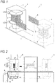
- FIG. 1 is a schematic configuration diagram of a friction material manufacturing apparatus according to an embodiment.
- a friction material manufacturing apparatus 1 is an apparatus for sintering friction materials for brakes, and includes: a jig 4 for clamping in a stacking direction, with a pressing mechanism 3, a stack 2 obtained by stacking workpieces, which are preforms of the friction materials; a transport mechanism that forms a transport path 5 of the jig 4; and a heating apparatus 6 provided in a way of the transport path 5 for heating the stack 2 clamped in the pressing mechanism 3 by the jig 4 with infrared rays from a lateral side with respect to the stacking direction.
- the friction material manufacturing apparatus 1 moves the jig 4 in a state where the stack 2 is clamped by the pressing mechanism 3 along the transport path 5, and heats the friction materials in the stack 2 by heating the stack 2 with the heating apparatus 6 in a way of the transport path 5.
- the friction material manufacturing apparatus 1 is not limited to a structure in which the stack 2 is clamped vertically, and may have a structure in which the stack 2 is clamped horizontally.
- the friction material is assumed to be used in, for example, various industrial equipment, transportation equipment, office equipment, or the like.
- the stack 2 is obtained by stacking, on a pressure plate, preforms each obtained by mixing a metal powder with an abrasive and/or a lubricant and pressing it into a thin plate shape, and further stacking a plurality of groups of assemblies each obtained by arranging an alumina setter on a friction surface side of the preform.
- the stack 2 can be realized by setting and stacking the preform, the pressure plate, and the setter on, for example, a jig for stacking.
- the jig 4 includes an accommodation portion 7 capable of accommodating the stack 2 in a state of being clamped by the pressing mechanism 3.
- the accommodation portion 7 is provided with a window through which near infrared rays of the heating apparatus 6 pass, as will be described later.
- the accommodation portion 7 is formed of a material having heat resistance to the heat of the heating apparatus 6.
- Fig. 2 is a structural view of the friction material manufacturing apparatus 1 as viewed from a lateral side of the transport path 5.
- Fig. 3 is a structural view of the friction material manufacturing apparatus 1 as viewed from a transport direction of the transport path 5.
- the friction material manufacturing apparatus 1 includes a transport mechanism 8 that forms the transport path 5 and a support member 9 that supports the heating apparatus 6.
- An inert gas cylinder 10 is provided together with the friction material manufacturing apparatus 1, and the inert gas cylinder 10 is connected to a gas introduction port 12 of the jig 4 via a hose 11.
- the inert gas supplied from the inert gas cylinder 10 flows into the accommodation portion 7 of the jig 4.
- Examples of the inert gas filled in the inert gas cylinder 10 include argon gas, nitrogen gas, and various other inert gases.
- the inert gas cylinder 10 is provided for the purpose of preventing oxidation during sintering by applying an inert gas atmosphere inside the accommodation portion 7 in which the stack 2 is accommodated.
- sintering may also be performed in a reducing gas atmosphere, in a combination atmosphere of an inert gas and a reducing gas, or in a reduced pressure atmosphere. Therefore, the hose 11 connecting the inert gas cylinder 10 and the gas introduction port 12 of the jig 4 is routed such that the jig 4 can be traced even when sliding along the transport path 5.
- the accommodation portion 7 is provided with a quartz glass 13 through which the near infrared rays of the heating apparatus 6 are transmitted.
- the accommodation portion 7 is basically formed of a metal material having heat resistance to heat of the heating apparatus 6, such as stainless steel, and is designed such that the quartz glass 13 is disposed at a portion irradiated by the near infrared rays of the heating apparatus 6 when the jig 4 is in the vicinity of the heating apparatus 6, and the near infrared rays of the heating apparatus 6 are unlikely to be irradiated onto unnecessary portions of the jig 4.
- each member is designed to have an appropriate size so that leakage of the inert gas flowing inside falls within a predetermined allowable range and expansion of the members caused by temperature rise by the heating apparatus 6 does not cause interference between the members.
- the inert gas of the inert gas cylinder 10 introduced into the accommodation portion 7 through the gas introduction port 12 passes through the accommodation portion 7 and is exhausted through a gas exhaust port 17 provided in the accommodation portion 7.
- the inert gas introduced into the accommodation portion 7 through the gas introduction port 12 prevents oxidation of the friction material, and exerts a cooling function of the members constituting the accommodation portion 7 and a contamination preventing function of the quartz glass 13, and thus an exhaust amount through the gas exhaust port 17 is adjusted in consideration of maintaining these functions.
- the transparent plate window covering the stack 2 from the lateral side with respect to the stacking direction is not limited to the quartz glass 13 as long as transmitting infrared light and having heat resistance.
- the pressing mechanism 3 provided in the accommodation portion 7 includes a support portion 14 that supports the stack 2 from above, and a pressing portion 15 that presses the stack 2 from below toward the support portion 14.
- the pressing portion 15 is a part raised and lowered vertically by an air cylinder 16.
- the air cylinder 16 is connected to a compressor that supplies high-pressure air via a pressure-resistant hose, and raises and lowers the pressing portion 15 in accordance with opening and closing of a valve provided in a way of a path for supplying the high-pressure air.
- a load cell for measuring a load applied to the stack 2 is provided in the pressing mechanism 3, and the magnitude of the load applied to the stack 2 can be adjusted.
- the pressing mechanism 3 is provided with a cooling structure such as a water-cooling jacket for preventing damage to the load cell due to the heat of the heating apparatus 6.
- the pressing mechanism 3 is only required to be able to press the stack 2, and may be, other than the air cylinder 16, for example, a coil spring, a lever in combination with a weight, a manual jack, a hydraulic cylinder, or various other pressing means.
- the jig 4 configured as described above can be slid along the transport path 5 by the transport mechanism 8.
- the transport mechanism 8 for sliding the jig 4 may be a roller-type conveyor on which the jig 4 is placed, or may be a linear guide that is fitted to a rail extending along the transport path 5.
- the transport mechanism 8 may be a manual mechanism without a power source that slides the jig 4, such as a motor, or may be an automatic mechanism including a power source.
- the jig 4 is transported on the transport path 5 while being advanced or stopped at an appropriate timing.
- the timing at which the jig 4 is advanced or stopped is determined according to a heating capacity of the heating apparatus 6, an atmosphere temperature in a plant in which the friction material manufacturing apparatus 1 is provided, a composition of the friction materials stacked in the stack 2, the number of friction materials stacked in the stack 2, the pressing force of the pressing mechanism 3, and other various factors.
- the heating apparatus 6 heats the stack 2 set in such a jig 4 by near infrared rays.
- the heating apparatus 6 includes a plurality of rod-shaped near infrared heaters extending along the direction of the transport path 5 on both sides thereof, and has a heating capacity capable of heating the stack 2 to about 1000°C.
- Each near infrared heater emits, for example, near infrared rays having a peak wavelength in a range of 1200 nm to 1700 nm.
- the near-infrared ray having such a wavelength is higher in permeability in substance than in far infrared rays, and thus is capable of heating the inside of the stack 2 without remaining in the vicinity of the surface even with respect to the stack 2 obtained by stacking friction materials. Therefore, it is suitable for heating the stack 2 with infrared rays through the quartz glass 13.
- energization is controlled for each combination of one to a plurality of the heats, and an appropriate amount of heat can be applied to each of an upper layer portion, a middle layer portion, and a lower layer portion of the stack 2.
- the energization pattern of each near infrared heater of the heating apparatus 6 is adjusted according to the heating capacity of the heating apparatus 6, the atmosphere temperature in a plant in which the friction material manufacturing apparatus 1 is provided, the composition of the friction materials stacked in the stack 2, the number of friction materials stacked in the stack 2, the pressing force of the pressing mechanism 3, and other various factors.
- the energization pattern of the heating apparatus 6 may be in accordance with a predetermined sequence set in advance, or in accordance with information of a radiation thermometer for measuring the temperature of the stack 2 in a non-contact manner, such as thermography.
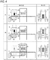
- Fig. 4 is a first diagram illustrating a method for using the friction material manufacturing apparatus 1.
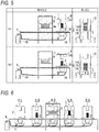
- Fig. 5 is a second diagram illustrating a method for using the friction material manufacturing apparatus 1.
- the air cylinder 16 is contracted to bring the pressing portion 15 to a lower limit position, and the stack 2 is set in the jig 4 in this state.
- the air cylinder 16 is extended to raise the pressure portion 15, and the stack 2 is clamped between the support portion 14 and the pressing portion 15.
- an open portion of the accommodation portion 7 is closed, and the inert gas of the inert gas cylinder 10 is supplied into the accommodation portion 7.
- the jig 4 is slid by the transport mechanism 8, and the jig 4 is moved to the vicinity of the heating apparatus 6. Then, the stack 2 is heated by the heating apparatus 6. When sintering of the friction materials stacked in the stack 2 proceeds, the jig 4 is slid at an appropriate timing to separate the jig 4 from the heating apparatus 6 as shown in (A) of Fig. 5 . Then, when the stack 2 is cooled by natural cooling or the like until the friction materials stacked in the stack 2 are cooled to an appropriate temperature, sintering of the friction materials stacked in the stack 2 is completed.
- the near infrared heaters have a temperature rise rate of 10 times to 20 times as compared with a resistance heater.
- the near infrared heaters have a peak wavelength shorter than in the range of 1700 nm to 2700 nm, which is the peak wavelength of medium-wavelength carbon heater or medium-wavelength infrared heater, and thus can output higher energy than the medium-wavelength carbon heater or medium-wavelength infrared heater, and can sinter a friction material of an inorganic substance obtained by mixing an abrasive and/or a lubricant into a metal powder in a relatively short time.
- the friction material manufacturing apparatus 1 of the embodiment described above since the jig 4 in which the stack 2 is set can pass through the vicinity of the heating apparatus 6 while being slid by the transport mechanism 8, for example, the friction materials can be fired in a large amount in a substantially continuous manner instead of a batch manner by being used as described below.
- Fig. 6 is a diagram showing a state where jigs 4 are arranged continuously.
- each jig 4 in which the stack 2 is set can pass through the vicinity of the heating apparatus 6 while being slid by the transport mechanism 8, for example, as shown in Fig. 6 , by providing the plurality of jigs 4 (4-1 to 5) in which the stack 2 is set in the transport path 5, a jig 4 whose heating of the stack 2 is completed in the heating apparatus 6 can be moved away from the heating apparatus 6, and a subsequent jig 4 in which a stack 2 before heating is set can be continuously slid and placed at the position of the heating apparatus 6, whereby heating and cooling of the friction materials can be performed at the same time.
- a region where the heating apparatus 6 is present in the transport path 5 can be regarded as a heating zone and a region other than the heating zone can be regarded as a cooling zone.
- sintering of the friction materials is performed only by the heating apparatus 6, but the sintering of the friction materials may also be performed in cooperation of the heating apparatus 6 and another heating apparatus.
- a convection oven using hot air may be provided next to the heating apparatus 6 including the near infrared heaters together with the friction material manufacturing apparatus 1, so that the heating apparatus 6 raises the temperature of the friction materials, and the convection oven maintains the temperature of the friction materials heated by the heating apparatus 6.
- the temperature of the friction materials may be maintained by independently changing outputs of the plurality of near infrared heaters of the heating apparatus 6.
- Fig. 7 is a diagram showing a modification of the friction material manufacturing apparatus 1.
- the friction material manufacturing apparatus 1 may be an apparatus in which a plurality of heating apparatuses 6 are provided along the transport path 5. If the friction material manufacturing apparatus 1 is provided with a plurality of heating apparatuses 6 along the transport path 5, the respective stacks 2 set in the plurality of jigs 4 can be simultaneously heated by the plurality of heating apparatuses 6. Therefore, the friction material manufacturing apparatus 1 of the present modification can sinter a large number of friction materials.
- the rod-shaped near infrared heaters constituting the heating apparatus have a peak wavelength of 1200 nm to 1700 nm, a total length of 405 mm, and a length of heating portion (effective length) of 340 mm.
- six near infrared heaters were arranged on the upper side, and three were arranged on the lower side of the stack 2 arranged to have the horizontal stacking direction.
- a jig corresponding to the jig 4 of the above embodiment was prepared by forming a pressing mechanism with a coil spring, and introducing an argon gas into a sealed accommodation portion formed from a heat-resistant metal component and a transparent quartz glass. Since the effective length of the near infrared heaters is 340 mm, by setting a frame of the jig to a length of about 540 mm, the metal component constituting the frame of the jig is unlikely to be directly irradiated by near infrared rays emitted from the near infrared heaters.
- argon gas was introduced into the accommodation portion through the introduction port of two systems, and discharged from the exhaust port of one system. Further, when the argon gas flows from the introduction port of the two systems into the accommodation portion, the argon gas was constantly cooled by being blown to the coil spring constituting the pressing mechanism, thereby preventing thermal deformation of the coil spring.
- a metal powder was mixed with an abrasive and a lubricant and pressed into a thin plate, so as to prepare six preforms of a cylindrical block having a diameter of 42 mm and a thickness of 12 mm. Then, the cylindrical blocks were stacked on a hot rolled steel plate corresponding to the pressure plate of the brake, and alumina was further interposed therebetween to form a stack. The stack was heated in a state applied with a load of 3.0 MPa by the coil spring. Heights of the upper and lower near infrared heaters were adjusted such that a distance between centers of the near infrared heaters and centers of the cylindrical blocks was 70 mm. Argon gas was continuously flowed into the accommodation portion at a pressure of 0.45 MPa. Gas replacement (purge) in the accommodation portion was 5 minutes.
- the near infrared heaters were controlled such that a full output of the upper and lower heaters was 20 kW, and an output ratio of the upper to the lower heaters was 16.8 to 4.9. Then, after a temperature of a thermocouple attached to the stack to be heated reached 950°C, the temperature was maintained at 950 ⁇ 15°C for 30 minutes, and then the energization of the near infrared heaters was turned off. In addition, the introduction of argon gas was continued until the stack to be heated reached normal temperature.
- the sintered friction materials produced by the method corresponding to the above embodiment are hereinafter referred to as examples.
- the evaluation results of comparison between the examples and comparative examples prepared with a sintering furnace using resistance heaters will be described below.
- the comparative examples were prepared in an argon gas atmosphere at a surface pressure of 3.0 MPa, a sintering temperature of 950°C, a maintaining time of 30 minutes, and a heating rate of 10°C / min.
- the sintering temperature reached 950°C in an extremely short time of about 1/10 as compared with the case of the comparative examples.
- the shrinkage factor and the surface hardness were similar in the examples and the comparative examples.
- the examples had a tendency to be 1.4 times to 1.6 times higher than that of the comparative examples.
- the examples were capable of producing sintered friction materials having performances similar as that of the comparative examples in a temperature rise time of about 90 minutes shorter than the comparative examples.
- the sintering temperature was set to 950 ⁇ 15°C
- the sintering retention time was set to 30 minutes
- the sintering surface pressure was set to 3.0 MPa
- the sintering temperature in the sintering process is preferably 900°C to 1300°C, more preferably 950°C to 1250°C.
- the sintering retention time is preferably 30 minutes to 180 minutes.
- the sintering surface pressure is preferably 1 MPa to 18 MPa. As long as the sintering temperature, the sintering retention time, and the sintering surface pressure are within these ranges, the same effect as in the above examples is exhibited.
- the friction material manufacturing apparatus 1 of the above embodiment can be used not only for manufacturing of sintered friction materials, but also for manufacturing of resin-based friction materials containing a large amount of organic materials, for example.
- a lower plate constituting a bottom surface and an upper plate constituting a top surface of the accommodation portion 7 may be configured as follows.
- Fig. 8 is a diagram illustrating an example of openings for gas provided on the upper plate and the lower plate.
- the accommodation portion 7 may be formed from, for example, a lower plate having five gas introduction ports LF1 to LF5 arranged side by side on a front side and five gas introduction ports LB1 to LB5 arranged side by side on a back side of the friction material manufacturing apparatus 1, and an upper plate having five gas exhaust ports UF1 to UF5 arranged side by side on the front side and five gas exhaust ports UB1 to UB5 arranged side by side on the back side of the friction material manufacturing apparatus 1.
- the lower plate is provided with a first internal flow path for supplying the gas to the gas introduction ports LF1 to LF5, and a second internal flow path for supplying the gas to the gas introduction ports LB1 to LB5.
- the accommodation portion 7 includes such upper plate and lower plate, the gas blown from the gas introduction ports LF1 to LF5, LB1 to LB5 flows along the surface of the quartz glass 13, and is discharged from the gas exhaust ports UF1 to UF5, UB1 to UB5. Therefore, the surface of the quartz glass 13 is prevented from contamination by the gas.
- FIG. 8 shows a state where ten gas openings are provided in each of the upper plate and the lower plate, the diameters and the numbers of the gas introduction ports LF1 to LF5, LB1 to LB5, the diameters and the numbers of the gas exhaust ports UF1 to UF5, UB1 to UB5, and a flow rate of the gas can be appropriately set according to a size, a shape, a heating temperature, and the like of the workpieces. Further, unnecessary openings may be closed with a plug, for example corresponding to, the size, shape, heating temperature, and the like of the workpieces.
- the support portion 14 that supports the stack 2 obtained by stacking the workpieces from above and/or the pressing portion 15 that presses the stack 2 from below toward the support portion 14 may include a heat insulating member at a portion in contact with the stack 2. If a heat insulating member is provided at the portion in contact with the stack 2, it is possible to prevent heat transfer from the workpieces constituting the stack 2 to the jig 4, and thus it is possible to prevent the workpieces on the lower portion and/or the upper portion of the stack 2 from having a lower temperature than the other workpieces. A pressing force of the pressing portion 15 is applied to the heat insulating member. Therefore, a material constituting the heat insulating member preferably has resistance against such pressing force. Examples of such material include a carbon plate material, an electrically insulating heat insulating plate such as NEOARK (registered trademark), and a calcium silicate heat insulating plate made such as LUMIBOARD (registered trademark).
- the jig 4 includes the accommodation portion 7, and the jig 4 moves in the transport path 5 together with the accommodation portion 7 so as to be heated from the outside of the accommodation portion 7 by the heating apparatus 6, whereas the friction material manufacturing apparatus 1 may be configured such that the accommodation portion 7 collectively accommodates the jig 4, the transport path 5, and the heating apparatus 6, or alternatively, the accommodation portion 7 accommodates the heating apparatus 6 and the jig 4 can move in and out from the accommodation portion 7.
- Fig. 9 is a diagram showing a first modification of the friction material manufacturing apparatus 1.
- the accommodation portion 7 may be configured to collectively accommodate the jig 4, the transport path 5, and the heating apparatus 6.
- the quartz glass 13 is not necessary. Therefore, supply of a gas for preventing contamination of the quartz glass 13 is not necessary, and a gas for discharging vaporized components vaporized from the workpieces due to heating is supplied into the accommodation portion 7.
- the accommodation portion 7 is provided with a door that allows the workpieces to be attached to the jig 4 or allows the jig 4 to move.
- Fig. 10 is a structural view of the friction material manufacturing apparatus according to the first modification as viewed from a lateral side of the transport path.
- the inert gas cylinder 10 is connected by a hose to the gas introduction portion of the accommodation portion 7 that collectively accommodates the jig 4, the transport path 5, and the heating apparatus 6.
- the jig 4 is accommodated in the accommodation portion 7, and is not connected to the inert gas cylinder 10.
- the hose connected to the inert gas cylinder 10 does not hinder movement of the jig 4. Therefore, the jig 4 can be easily moved along the transport path 5.
- Fig. 11 is a diagram showing a second modification of the friction material manufacturing apparatus 1.
- the friction material manufacturing apparatus 1 of the above embodiment may be such that, for example, as shown in Fig. 11 , the accommodation portion 7 is provided in the heating apparatus 6, and the jig 4 before heating and the jig 4 after heating are disposed outside the accommodation portion 7.
- an opening that allows the jig 4 to move in and out, and a door for opening and closing the opening are provided on both side surfaces of the accommodation portion 7.
- the inside of the accommodation portion can be filled with the gas supplied from the inert gas cylinder 10.
- the quartz glass 13 is not necessary.
- Fig. 12 is a diagram showing a third modification of the friction material manufacturing apparatus 1.
- the friction material manufacturing apparatus 1 of the above embodiment may be such that, for example, as shown in Fig. 12 , the jig 4 before heating and the heating apparatus 6 are accommodated in the accommodation portion 7, and the jig 4 after heating is disposed outside the accommodation portion 7.
- an opening that allows the jig 4 to move in and out, and a door for opening and closing the opening are provided on a side surface of the accommodation portion 7.
- the inside of the accommodation portion can be filled with the gas supplied from the inert gas cylinder 10.
- the quartz glass 13 is not necessary.
- Fig. 13 is a diagram showing a fourth modification of the friction material manufacturing apparatus 1.
- the friction material manufacturing apparatus 1 of the above embodiment may be such that, for example, as shown in Fig. 13 , the jig 4 after heating and the heating apparatus 6 are accommodated in the accommodation portion 7, and the jig 4 before heating is disposed outside the accommodation portion 7.
- an opening that allows the jig 4 to move in and out, and a door for opening and closing the opening are provided on a side surface of the accommodation portion 7.
- the inside of the accommodation portion can be filled with the gas supplied from the inert gas cylinder 10.
- the quartz glass 13 is not necessary.
Landscapes
- Engineering & Computer Science (AREA)
- Manufacturing & Machinery (AREA)
- Mechanical Engineering (AREA)
- Braking Arrangements (AREA)
Abstract
Description
- The present application discloses a friction material manufacturing apparatus and a friction material manufacturing method.
- Brakes used in vehicles and other various machines are usually provided with friction materials. The friction material is a member that converts kinetic energy into thermal energy, and thus is required to exert a predetermined braking force even at a high temperature. Therefore, in order to exert the predetermined braking force even when the friction material is used in a high-temperature state, various measures for shaping the friction material at an appropriate temperature are made in a manufacturing line of the friction material (see
Patent Literatures 1 to 3). -
- Patent Literature 1:
JP-A-2016-522362 - Patent Literature 2:
Japanese Patent No. 6113927 - Patent Literature 3:
Chinese Utility Model No. 205437147 - For example, in order to efficiently manufacture a friction material having a relatively high temperature during molding as typified by a friction material obtained by sintering a metal powder, it is desired to rapidly heat the friction material. However, when the temperature of the friction material is raised by a hot plate, heat is transferred from a heat source to the friction material via the hot plate, and thus a temperature rise rate of the friction material greatly depends on a heat capacity of the hot plate in accordance with temperature rise of the heat plate per se. Further, when the temperature of the friction material is raised in a convection oven, heat is transferred from the heat source to the friction material via a gas flow, and thus it is difficult to quickly raise the temperature of the friction material via the gas, which has poor heat transfer property.
- An object of the present invention is to enable efficient manufacture of a friction material.
- In order to solve the above problem, in the present invention, a stack of workpieces, which are preforms of friction materials, is clamped by a jig, and in this state, the stack is heated with infrared rays from a lateral side with respect to a stacking direction.
- More specifically, the present invention is a friction material manufacturing apparatus configured to sinter friction materials, and includes: a jig configured to clamp a stack of workpieces, which are preforms of the friction materials, in a stacking direction; a transport mechanism that forms a transport path of the jig; and a heating apparatus provided in a way of the transport path and configured to heat the stack clamped by the jig with infrared rays from a lateral side with respect to the stacking direction.
- The friction material manufacturing apparatus described above uses infrared rays to heat the stack clamped by the jig, and thus is capable of heating a portion of the stack in a selectively concentrated manner. Therefore, for example, the heating target can be efficiently heated as compared with a heating method that is difficult to heat a specific place in a selectively concentrated manner, such as in a convection method.
- Since the friction material manufacturing apparatus described above has an aspect in which the heating apparatus is provided in a way of the transport path and the jig for clamping the stack to be heated is transported by the transport mechanism, the stack that has been heated by the heating apparatus can be separated integrally with the jig from the heating apparatus. Therefore, while waiting for a decrease in the temperature of the stack that has been heated by the heating apparatus, a stack clamped by another jig can be continuously heated by the heating apparatus.
- Therefore, according to the friction material manufacturing apparatus described above, it is possible to efficiently manufacture friction materials.
- The jig may include: a support portion configured to support the stack from one side in the stacking direction; and a pressing portion configured to press the stack from the other side in the stacking direction toward the support portion. By using such a jig, the stack that has been heated by the heating apparatus can be separated from the heating apparatus integrally with the jig from the heating apparatus while maintaining a pressed state. For this reason it is possible to quickly replace the stack to be heated in the heating apparatus.
- The heating apparatus may include an element configured to emit infrared rays at a position that is on the lateral side of the stack in a state where the jig is at a position of the heating apparatus. In the heating apparatus having the element configured to emit infrared rays at such a position, the stack clamped by the jig can be irradiated by the infrared rays of the element only by simply conveying the jig clamping the stack to be heated to the vicinity of the heating apparatus by the transport mechanism, and thus it is possible to quickly replace the stack to be heated in the heating apparatus.
- The jig may include a window made from a transparent plate configured to cover the stack from the lateral side with respect to the stacking direction, and may include an accommodation portion configured to accommodate the stack. In this case, the jig may include a gas introduction portion configured to introduce an inert gas into the accommodation portion. The friction material manufacturing apparatus described above uses infrared rays for heating, and thus is capable of heating through such window made from a transparent plate. Therefore, by adopting such configuration in which the accommodation portion is provided in the jig and heating by infrared rays is performed through the window made from a transparent plate, for example, the inside of the accommodation portion can be applied with an inert gas atmosphere.
- The friction material manufacturing apparatus may further include an accommodation portion configured to accommodate the jig, the transport mechanism, and the heating apparatus. The accommodation portion may include a gas introduction portion configured to introduce an inert gas. In this case, for example, even if the inside of the accommodation portion is applied with an inert gas atmosphere, the jig can be easily moved.
- In addition, the friction material manufacturing apparatus may further include an accommodation portion configured to accommodate the heating apparatus, and allow the jig to move in and out. The accommodation portion may include a door at an opening portion through which the jig is to move in and out. In this case, the accommodation portion may include an introduction portion configured to introduce an inert gas. By providing the accommodation portion in the heating apparatus in this manner and closing the accommodation portion after the jig is transported to the vicinity of the heating apparatus by the transport mechanism, the inside of the accommodation portion can be applied with an inert gas atmosphere.
- The jig may include a heat insulating member at a portion to be in contact with the stack. In this case, heat transfer from the stack to the jig can be prevented.
- The heating apparatus may be a near infrared heater having a peak wavelength in a range of 1200 nm to 1700 nm. The near infrared ray having such a wavelength is higher in permeability in substance than, for example, in mid-infrared rays having a peak wavelength of 1700 nm to 2700 nm, and thus is capable of heating the inside of the stack with high energy without remaining in the vicinity of the surface even with respect to a stack obtained by stacking friction materials. Therefore, it is suitable for heating a heating object that whose center portion cannot be easily heated, such as a stack obtained by stacking friction materials.
- The invention can also be understood from an aspect of method. For example, the present invention may be a friction material manufacturing method for sintering friction materials, the friction material manufacturing method including: clamping, by a jig, a stack of workpieces, which are preforms of the friction materials, in a stacking direction; transporting the jig along a transport path formed by a transport mechanism; and heating, by a heating apparatus provided in a way of the transport path, the stack clamped by the jig with infrared rays from a lateral side with respect to the stacking direction.
- The present invention enables efficient manufacture of a friction material.
-
- [
Fig. 1] Fig. 1 is a schematic configuration diagram of a friction material manufacturing apparatus according to an embodiment. - [
Fig. 2] Fig. 2 is a structural view of the friction material manufacturing apparatus as viewed from a lateral side of a transport path. - [
Fig. 3] Fig. 3 is a structural view of the friction material manufacturing apparatus as viewed from a transport direction of the transport path. - [
Fig. 4] Fig. 4 is a first diagram illustrating a method for using the friction material manufacturing apparatus. - [
Fig. 5] Fig. 5 is a second diagram illustrating a method for using the friction material manufacturing apparatus. - [
Fig. 6] Fig. 6 is a diagram showing a state where jigs are arranged continuously. - [
Fig. 7] Fig. 7 is a diagram showing a modification of the friction material manufacturing apparatus. - [
Fig. 8] Fig. 8 is a diagram illustrating an example of openings for gas provided on an upper plate and a lower plate. - [
Fig. 9] Fig. 9 is a diagram showing a first modification of the friction material manufacturing apparatus. - [
Fig. 10] Fig. 10 is a structural view of the friction material manufacturing apparatus according to the first modification as viewed from a lateral side of the transport path. - [
Fig. 11] Fig. 11 is a diagram showing a second modification of the friction material manufacturing apparatus. - [
Fig. 12] Fig. 12 is a diagram showing a third modification of the friction material manufacturing apparatus. - [
Fig. 13] Fig. 13 is a diagram showing a fourth modification of the friction material manufacturing apparatus. - Embodiments of the present invention will be described below. The following embodiments illustrate embodiments of the present invention, and the technical scope of the present invention is not limited to the following embodiments.
-
Fig. 1 is a schematic configuration diagram of a friction material manufacturing apparatus according to an embodiment. A frictionmaterial manufacturing apparatus 1 is an apparatus for sintering friction materials for brakes, and includes: ajig 4 for clamping in a stacking direction, with apressing mechanism 3, astack 2 obtained by stacking workpieces, which are preforms of the friction materials; a transport mechanism that forms atransport path 5 of thejig 4; and aheating apparatus 6 provided in a way of thetransport path 5 for heating thestack 2 clamped in thepressing mechanism 3 by thejig 4 with infrared rays from a lateral side with respect to the stacking direction. The frictionmaterial manufacturing apparatus 1 moves thejig 4 in a state where thestack 2 is clamped by thepressing mechanism 3 along thetransport path 5, and heats the friction materials in thestack 2 by heating thestack 2 with theheating apparatus 6 in a way of thetransport path 5. The frictionmaterial manufacturing apparatus 1 is not limited to a structure in which thestack 2 is clamped vertically, and may have a structure in which thestack 2 is clamped horizontally. The friction material is assumed to be used in, for example, various industrial equipment, transportation equipment, office equipment, or the like. - The
stack 2 is obtained by stacking, on a pressure plate, preforms each obtained by mixing a metal powder with an abrasive and/or a lubricant and pressing it into a thin plate shape, and further stacking a plurality of groups of assemblies each obtained by arranging an alumina setter on a friction surface side of the preform. Thestack 2 can be realized by setting and stacking the preform, the pressure plate, and the setter on, for example, a jig for stacking. - The
jig 4 includes anaccommodation portion 7 capable of accommodating thestack 2 in a state of being clamped by thepressing mechanism 3. Theaccommodation portion 7 is provided with a window through which near infrared rays of theheating apparatus 6 pass, as will be described later. Theaccommodation portion 7 is formed of a material having heat resistance to the heat of theheating apparatus 6. - The components of the friction
material manufacturing apparatus 1 will be described in detail.Fig. 2 is a structural view of the frictionmaterial manufacturing apparatus 1 as viewed from a lateral side of thetransport path 5.Fig. 3 is a structural view of the frictionmaterial manufacturing apparatus 1 as viewed from a transport direction of thetransport path 5. - The friction
material manufacturing apparatus 1 includes atransport mechanism 8 that forms thetransport path 5 and asupport member 9 that supports theheating apparatus 6. Aninert gas cylinder 10 is provided together with the frictionmaterial manufacturing apparatus 1, and theinert gas cylinder 10 is connected to agas introduction port 12 of thejig 4 via ahose 11. The inert gas supplied from theinert gas cylinder 10 flows into theaccommodation portion 7 of thejig 4. Examples of the inert gas filled in theinert gas cylinder 10 include argon gas, nitrogen gas, and various other inert gases. Theinert gas cylinder 10 is provided for the purpose of preventing oxidation during sintering by applying an inert gas atmosphere inside theaccommodation portion 7 in which thestack 2 is accommodated. In addition to the inert gas atmosphere, sintering may also be performed in a reducing gas atmosphere, in a combination atmosphere of an inert gas and a reducing gas, or in a reduced pressure atmosphere. Therefore, thehose 11 connecting theinert gas cylinder 10 and thegas introduction port 12 of thejig 4 is routed such that thejig 4 can be traced even when sliding along thetransport path 5. - The
accommodation portion 7 is provided with aquartz glass 13 through which the near infrared rays of theheating apparatus 6 are transmitted. Theaccommodation portion 7 is basically formed of a metal material having heat resistance to heat of theheating apparatus 6, such as stainless steel, and is designed such that thequartz glass 13 is disposed at a portion irradiated by the near infrared rays of theheating apparatus 6 when thejig 4 is in the vicinity of theheating apparatus 6, and the near infrared rays of theheating apparatus 6 are unlikely to be irradiated onto unnecessary portions of thejig 4. In thequartz glass 13 and the other parts of theaccommodation portion 7 formed of the metal material, each member is designed to have an appropriate size so that leakage of the inert gas flowing inside falls within a predetermined allowable range and expansion of the members caused by temperature rise by theheating apparatus 6 does not cause interference between the members. The inert gas of theinert gas cylinder 10 introduced into theaccommodation portion 7 through thegas introduction port 12 passes through theaccommodation portion 7 and is exhausted through agas exhaust port 17 provided in theaccommodation portion 7. The inert gas introduced into theaccommodation portion 7 through thegas introduction port 12 prevents oxidation of the friction material, and exerts a cooling function of the members constituting theaccommodation portion 7 and a contamination preventing function of thequartz glass 13, and thus an exhaust amount through thegas exhaust port 17 is adjusted in consideration of maintaining these functions. The transparent plate window covering thestack 2 from the lateral side with respect to the stacking direction is not limited to thequartz glass 13 as long as transmitting infrared light and having heat resistance. - The
pressing mechanism 3 provided in theaccommodation portion 7 includes asupport portion 14 that supports thestack 2 from above, and apressing portion 15 that presses thestack 2 from below toward thesupport portion 14. Thepressing portion 15 is a part raised and lowered vertically by anair cylinder 16. Theair cylinder 16 is connected to a compressor that supplies high-pressure air via a pressure-resistant hose, and raises and lowers thepressing portion 15 in accordance with opening and closing of a valve provided in a way of a path for supplying the high-pressure air. In addition, a load cell for measuring a load applied to thestack 2 is provided in thepressing mechanism 3, and the magnitude of the load applied to thestack 2 can be adjusted. Thepressing mechanism 3 is provided with a cooling structure such as a water-cooling jacket for preventing damage to the load cell due to the heat of theheating apparatus 6. Thepressing mechanism 3 is only required to be able to press thestack 2, and may be, other than theair cylinder 16, for example, a coil spring, a lever in combination with a weight, a manual jack, a hydraulic cylinder, or various other pressing means. - The
jig 4 configured as described above can be slid along thetransport path 5 by thetransport mechanism 8. Thetransport mechanism 8 for sliding thejig 4 may be a roller-type conveyor on which thejig 4 is placed, or may be a linear guide that is fitted to a rail extending along thetransport path 5. Thetransport mechanism 8 may be a manual mechanism without a power source that slides thejig 4, such as a motor, or may be an automatic mechanism including a power source. - The
jig 4 is transported on thetransport path 5 while being advanced or stopped at an appropriate timing. The timing at which thejig 4 is advanced or stopped is determined according to a heating capacity of theheating apparatus 6, an atmosphere temperature in a plant in which the frictionmaterial manufacturing apparatus 1 is provided, a composition of the friction materials stacked in thestack 2, the number of friction materials stacked in thestack 2, the pressing force of thepressing mechanism 3, and other various factors. - The
heating apparatus 6 heats thestack 2 set in such ajig 4 by near infrared rays. Theheating apparatus 6 includes a plurality of rod-shaped near infrared heaters extending along the direction of thetransport path 5 on both sides thereof, and has a heating capacity capable of heating thestack 2 to about 1000°C. - Each near infrared heater emits, for example, near infrared rays having a peak wavelength in a range of 1200 nm to 1700 nm. The near-infrared ray having such a wavelength is higher in permeability in substance than in far infrared rays, and thus is capable of heating the inside of the
stack 2 without remaining in the vicinity of the surface even with respect to thestack 2 obtained by stacking friction materials. Therefore, it is suitable for heating thestack 2 with infrared rays through thequartz glass 13. - In the near infrared heaters, energization is controlled for each combination of one to a plurality of the heats, and an appropriate amount of heat can be applied to each of an upper layer portion, a middle layer portion, and a lower layer portion of the
stack 2. The energization pattern of each near infrared heater of theheating apparatus 6 is adjusted according to the heating capacity of theheating apparatus 6, the atmosphere temperature in a plant in which the frictionmaterial manufacturing apparatus 1 is provided, the composition of the friction materials stacked in thestack 2, the number of friction materials stacked in thestack 2, the pressing force of thepressing mechanism 3, and other various factors. The energization pattern of theheating apparatus 6 may be in accordance with a predetermined sequence set in advance, or in accordance with information of a radiation thermometer for measuring the temperature of thestack 2 in a non-contact manner, such as thermography. - Next, a method for using the friction
material manufacturing apparatus 1 will be described.Fig. 4 is a first diagram illustrating a method for using the frictionmaterial manufacturing apparatus 1.Fig. 5 is a second diagram illustrating a method for using the frictionmaterial manufacturing apparatus 1. When the friction material is sintered using the frictionmaterial manufacturing apparatus 1, first, as shown in (A) ofFig. 4 , theair cylinder 16 is contracted to bring thepressing portion 15 to a lower limit position, and thestack 2 is set in thejig 4 in this state. Next, as shown in (B) ofFig. 4 , theair cylinder 16 is extended to raise thepressure portion 15, and thestack 2 is clamped between thesupport portion 14 and thepressing portion 15. Then, an open portion of theaccommodation portion 7 is closed, and the inert gas of theinert gas cylinder 10 is supplied into theaccommodation portion 7. - When the
heating apparatus 6 is ready for heating in this manner, as shown in (C) ofFig. 4 , thejig 4 is slid by thetransport mechanism 8, and thejig 4 is moved to the vicinity of theheating apparatus 6. Then, thestack 2 is heated by theheating apparatus 6. When sintering of the friction materials stacked in thestack 2 proceeds, thejig 4 is slid at an appropriate timing to separate thejig 4 from theheating apparatus 6 as shown in (A) ofFig. 5 . Then, when thestack 2 is cooled by natural cooling or the like until the friction materials stacked in thestack 2 are cooled to an appropriate temperature, sintering of the friction materials stacked in thestack 2 is completed. When sintering of the friction materials stacked in thestack 2 is completed, as shown in (B) ofFig. 5 , theair cylinder 16 is contracted to bring thepressing portion 15 to the lower limit position, and thestack 2 is removed from thejig 4 in this state. Thejig 4 from which thestack 2 is removed can be immediately used for sintering other friction materials. - The near infrared heaters have a temperature rise rate of 10 times to 20 times as compared with a resistance heater. In addition, the near infrared heaters have a peak wavelength shorter than in the range of 1700 nm to 2700 nm, which is the peak wavelength of medium-wavelength carbon heater or medium-wavelength infrared heater, and thus can output higher energy than the medium-wavelength carbon heater or medium-wavelength infrared heater, and can sinter a friction material of an inorganic substance obtained by mixing an abrasive and/or a lubricant into a metal powder in a relatively short time.
- In the friction
material manufacturing apparatus 1 of the embodiment described above, since thejig 4 in which thestack 2 is set can pass through the vicinity of theheating apparatus 6 while being slid by thetransport mechanism 8, for example, the friction materials can be fired in a large amount in a substantially continuous manner instead of a batch manner by being used as described below. -
Fig. 6 is a diagram showing a state wherejigs 4 are arranged continuously. In the frictionmaterial manufacturing apparatus 1, since eachjig 4 in which thestack 2 is set can pass through the vicinity of theheating apparatus 6 while being slid by thetransport mechanism 8, for example, as shown inFig. 6 , by providing the plurality of jigs 4 (4-1 to 5) in which thestack 2 is set in thetransport path 5, ajig 4 whose heating of thestack 2 is completed in theheating apparatus 6 can be moved away from theheating apparatus 6, and asubsequent jig 4 in which astack 2 before heating is set can be continuously slid and placed at the position of theheating apparatus 6, whereby heating and cooling of the friction materials can be performed at the same time. Therefore, it is possible to increase the use efficiency of theheating apparatus 6 as much as possible. Since the frictionmaterial manufacturing apparatus 1 can be used in this manner, a region where theheating apparatus 6 is present in thetransport path 5 can be regarded as a heating zone and a region other than the heating zone can be regarded as a cooling zone. - In the friction
material manufacturing apparatus 1 of the above embodiment, sintering of the friction materials is performed only by theheating apparatus 6, but the sintering of the friction materials may also be performed in cooperation of theheating apparatus 6 and another heating apparatus. For example, a convection oven using hot air may be provided next to theheating apparatus 6 including the near infrared heaters together with the frictionmaterial manufacturing apparatus 1, so that theheating apparatus 6 raises the temperature of the friction materials, and the convection oven maintains the temperature of the friction materials heated by theheating apparatus 6. The temperature of the friction materials may be maintained by independently changing outputs of the plurality of near infrared heaters of theheating apparatus 6. -
Fig. 7 is a diagram showing a modification of the frictionmaterial manufacturing apparatus 1. For example, as shown inFig. 7 , the frictionmaterial manufacturing apparatus 1 may be an apparatus in which a plurality ofheating apparatuses 6 are provided along thetransport path 5. If the frictionmaterial manufacturing apparatus 1 is provided with a plurality ofheating apparatuses 6 along thetransport path 5, therespective stacks 2 set in the plurality ofjigs 4 can be simultaneously heated by the plurality ofheating apparatuses 6. Therefore, the frictionmaterial manufacturing apparatus 1 of the present modification can sinter a large number of friction materials. - A case of producing sintered friction materials using near infrared heaters and a case of producing sintered friction materials using resistance heaters were compared and verified, and the results are shown below. In this verification, the
stack 2 was placed such that the stacking direction of thestack 2 was horizontal instead of vertical as in the embodiment described above, and thestack 2 was heated from the upper side and the lower side. - In the present verification, the rod-shaped near infrared heaters constituting the heating apparatus have a peak wavelength of 1200 nm to 1700 nm, a total length of 405 mm, and a length of heating portion (effective length) of 340 mm. In this verification, six near infrared heaters were arranged on the upper side, and three were arranged on the lower side of the
stack 2 arranged to have the horizontal stacking direction. - In the present verification, a jig corresponding to the
jig 4 of the above embodiment was prepared by forming a pressing mechanism with a coil spring, and introducing an argon gas into a sealed accommodation portion formed from a heat-resistant metal component and a transparent quartz glass. Since the effective length of the near infrared heaters is 340 mm, by setting a frame of the jig to a length of about 540 mm, the metal component constituting the frame of the jig is unlikely to be directly irradiated by near infrared rays emitted from the near infrared heaters. - In this verification, argon gas was introduced into the accommodation portion through the introduction port of two systems, and discharged from the exhaust port of one system. Further, when the argon gas flows from the introduction port of the two systems into the accommodation portion, the argon gas was constantly cooled by being blown to the coil spring constituting the pressing mechanism, thereby preventing thermal deformation of the coil spring.
- In this verification, a metal powder was mixed with an abrasive and a lubricant and pressed into a thin plate, so as to prepare six preforms of a cylindrical block having a diameter of 42 mm and a thickness of 12 mm. Then, the cylindrical blocks were stacked on a hot rolled steel plate corresponding to the pressure plate of the brake, and alumina was further interposed therebetween to form a stack. The stack was heated in a state applied with a load of 3.0 MPa by the coil spring. Heights of the upper and lower near infrared heaters were adjusted such that a distance between centers of the near infrared heaters and centers of the cylindrical blocks was 70 mm. Argon gas was continuously flowed into the accommodation portion at a pressure of 0.45 MPa. Gas replacement (purge) in the accommodation portion was 5 minutes.
- The near infrared heaters were controlled such that a full output of the upper and lower heaters was 20 kW, and an output ratio of the upper to the lower heaters was 16.8 to 4.9. Then, after a temperature of a thermocouple attached to the stack to be heated reached 950°C, the temperature was maintained at 950 ± 15°C for 30 minutes, and then the energization of the near infrared heaters was turned off. In addition, the introduction of argon gas was continued until the stack to be heated reached normal temperature.
- The sintered friction materials produced by the method corresponding to the above embodiment are hereinafter referred to as examples. The evaluation results of comparison between the examples and comparative examples prepared with a sintering furnace using resistance heaters will be described below. The comparative examples were prepared in an argon gas atmosphere at a surface pressure of 3.0 MPa, a sintering temperature of 950°C, a maintaining time of 30 minutes, and a heating rate of 10°C / min.
- In this evaluation, the following five items were evaluated.
- 1. Time until the sintering temperature reaches 950°C
- 2. Shrinkage factor
- 3. Surface hardness
- 4. Base material shear strength
- 5. Pressure plate (PP) adhesive shear strength
- The evaluation results of the items are shown in the following table.
[Table 1] Heated samples Examples Comparative examples Heating method Near infrared heater Resistance heater Time until reaching 950°C (min) 7.2 95 Shrinkage factor (%) 7.7 (6.7 to 8.3) 8.9 (8.4 to 9.3) Surface hardness (HRS) 48 (30 to 58) 50 (46 to 53) Base material shear strength (MPa) 3.6 (2.9 to 4.5) 2.5 (2.2 to 2.6) PP adhesive shear strength (MPa) 30.7 (27.6 to 33.8) 19.1 (18.3 to 20.0) * The numbers are average values, and the numbers in the parentheses indicate minimum values and maximum values. - As can be seen from the table above, in the case of the examples, the sintering temperature reached 950°C in an extremely short time of about 1/10 as compared with the case of the comparative examples. In addition, the shrinkage factor and the surface hardness were similar in the examples and the comparative examples. Regarding the base material shear strength and the PP adhesive shear strength, the examples had a tendency to be 1.4 times to 1.6 times higher than that of the comparative examples.
- From the above results, it was confirmed that the examples were capable of producing sintered friction materials having performances similar as that of the comparative examples in a temperature rise time of about 90 minutes shorter than the comparative examples. In this verification, the sintering temperature was set to 950 ± 15°C, the sintering retention time was set to 30 minutes, and the sintering surface pressure was set to 3.0 MPa, whereas the sintering temperature in the sintering process is preferably 900°C to 1300°C, more preferably 950°C to 1250°C. The sintering retention time is preferably 30 minutes to 180 minutes. The sintering surface pressure is preferably 1 MPa to 18 MPa. As long as the sintering temperature, the sintering retention time, and the sintering surface pressure are within these ranges, the same effect as in the above examples is exhibited.
- Although manufacturing of sintered friction materials is assumed in the above description, the friction
material manufacturing apparatus 1 of the above embodiment can be used not only for manufacturing of sintered friction materials, but also for manufacturing of resin-based friction materials containing a large amount of organic materials, for example. - A lower plate constituting a bottom surface and an upper plate constituting a top surface of the
accommodation portion 7 may be configured as follows.Fig. 8 is a diagram illustrating an example of openings for gas provided on the upper plate and the lower plate. Theaccommodation portion 7 may be formed from, for example, a lower plate having five gas introduction ports LF1 to LF5 arranged side by side on a front side and five gas introduction ports LB1 to LB5 arranged side by side on a back side of the frictionmaterial manufacturing apparatus 1, and an upper plate having five gas exhaust ports UF1 to UF5 arranged side by side on the front side and five gas exhaust ports UB1 to UB5 arranged side by side on the back side of the frictionmaterial manufacturing apparatus 1. In this case, the lower plate is provided with a first internal flow path for supplying the gas to the gas introduction ports LF1 to LF5, and a second internal flow path for supplying the gas to the gas introduction ports LB1 to LB5. - If the
accommodation portion 7 includes such upper plate and lower plate, the gas blown from the gas introduction ports LF1 to LF5, LB1 to LB5 flows along the surface of thequartz glass 13, and is discharged from the gas exhaust ports UF1 to UF5, UB1 to UB5. Therefore, the surface of thequartz glass 13 is prevented from contamination by the gas. AlthoughFig. 8 shows a state where ten gas openings are provided in each of the upper plate and the lower plate, the diameters and the numbers of the gas introduction ports LF1 to LF5, LB1 to LB5, the diameters and the numbers of the gas exhaust ports UF1 to UF5, UB1 to UB5, and a flow rate of the gas can be appropriately set according to a size, a shape, a heating temperature, and the like of the workpieces. Further, unnecessary openings may be closed with a plug, for example corresponding to, the size, shape, heating temperature, and the like of the workpieces. - In addition, the
support portion 14 that supports thestack 2 obtained by stacking the workpieces from above and/or thepressing portion 15 that presses thestack 2 from below toward thesupport portion 14 may include a heat insulating member at a portion in contact with thestack 2. If a heat insulating member is provided at the portion in contact with thestack 2, it is possible to prevent heat transfer from the workpieces constituting thestack 2 to thejig 4, and thus it is possible to prevent the workpieces on the lower portion and/or the upper portion of thestack 2 from having a lower temperature than the other workpieces. A pressing force of thepressing portion 15 is applied to the heat insulating member.
Therefore, a material constituting the heat insulating member preferably has resistance against such pressing force. Examples of such material include a carbon plate material, an electrically insulating heat insulating plate such as NEOARK (registered trademark), and a calcium silicate heat insulating plate made such as LUMIBOARD (registered trademark). - In the above embodiment, the
jig 4 includes theaccommodation portion 7, and thejig 4 moves in thetransport path 5 together with theaccommodation portion 7 so as to be heated from the outside of theaccommodation portion 7 by theheating apparatus 6, whereas the frictionmaterial manufacturing apparatus 1 may be configured such that theaccommodation portion 7 collectively accommodates thejig 4, thetransport path 5, and theheating apparatus 6, or alternatively, theaccommodation portion 7 accommodates theheating apparatus 6 and thejig 4 can move in and out from theaccommodation portion 7. -
Fig. 9 is a diagram showing a first modification of the frictionmaterial manufacturing apparatus 1. In the frictionmaterial manufacturing apparatus 1 of the above embodiment, for example, as shown inFig. 9 , theaccommodation portion 7 may be configured to collectively accommodate thejig 4, thetransport path 5, and theheating apparatus 6. In the present modification, since theheating apparatus 6 is accommodated in theaccommodation portion 7, thequartz glass 13 is not necessary. Therefore, supply of a gas for preventing contamination of thequartz glass 13 is not necessary, and a gas for discharging vaporized components vaporized from the workpieces due to heating is supplied into theaccommodation portion 7. In this case, it is preferable that theaccommodation portion 7 is provided with a door that allows the workpieces to be attached to thejig 4 or allows thejig 4 to move. - In the friction
material manufacturing apparatus 1 of this modified example, it is not necessary to connect thejig 4 to theinert gas cylinder 10 by thehose 11. Therefore, thejig 4 can be easily handled.Fig. 10 is a structural view of the friction material manufacturing apparatus according to the first modification as viewed from a lateral side of the transport path. As shown inFig. 10 , theinert gas cylinder 10 is connected by a hose to the gas introduction portion of theaccommodation portion 7 that collectively accommodates thejig 4, thetransport path 5, and theheating apparatus 6. Thejig 4 is accommodated in theaccommodation portion 7, and is not connected to theinert gas cylinder 10. Therefore, in the frictionmaterial manufacturing apparatus 1 according to the present modification, when thejig 4 is moved along thetransport path 5, the hose connected to theinert gas cylinder 10 does not hinder movement of thejig 4. Therefore, thejig 4 can be easily moved along thetransport path 5. -
Fig. 11 is a diagram showing a second modification of the frictionmaterial manufacturing apparatus 1. The frictionmaterial manufacturing apparatus 1 of the above embodiment may be such that, for example, as shown inFig. 11 , theaccommodation portion 7 is provided in theheating apparatus 6, and thejig 4 before heating and thejig 4 after heating are disposed outside theaccommodation portion 7. In this case, an opening that allows thejig 4 to move in and out, and a door for opening and closing the opening are provided on both side surfaces of theaccommodation portion 7. When the opening is closed by the door to close the accommodation portion, the inside of the accommodation portion can be filled with the gas supplied from theinert gas cylinder 10. In this modification, similarly to the first modification, since theheating apparatus 6 is accommodated in theaccommodation portion 7, thequartz glass 13 is not necessary. -
Fig. 12 is a diagram showing a third modification of the frictionmaterial manufacturing apparatus 1. The frictionmaterial manufacturing apparatus 1 of the above embodiment may be such that, for example, as shown inFig. 12 , thejig 4 before heating and theheating apparatus 6 are accommodated in theaccommodation portion 7, and thejig 4 after heating is disposed outside theaccommodation portion 7. In this case, an opening that allows thejig 4 to move in and out, and a door for opening and closing the opening are provided on a side surface of theaccommodation portion 7. When the opening is closed by the door to close the accommodation portion, the inside of the accommodation portion can be filled with the gas supplied from theinert gas cylinder 10. In this modification, similarly to the first modification and the second modification, since theheating apparatus 6 is accommodated in theaccommodation portion 7, thequartz glass 13 is not necessary. -
Fig. 13 is a diagram showing a fourth modification of the frictionmaterial manufacturing apparatus 1. The frictionmaterial manufacturing apparatus 1 of the above embodiment may be such that, for example, as shown inFig. 13 , thejig 4 after heating and theheating apparatus 6 are accommodated in theaccommodation portion 7, and thejig 4 before heating is disposed outside theaccommodation portion 7. In this case, an opening that allows thejig 4 to move in and out, and a door for opening and closing the opening are provided on a side surface of theaccommodation portion 7. When the opening is closed by the door to close the accommodation portion, the inside of the accommodation portion can be filled with the gas supplied from theinert gas cylinder 10. In this modification, similarly to the first modification, the second modification, and the third modification, since theheating apparatus 6 is accommodated in theaccommodation portion 7, thequartz glass 13 is not necessary. - Although the embodiments are described above with reference to the drawings, it is needless to say that the present invention is not limited to such examples. It will be apparent to those skilled in the art that various changes and modifications may be conceived within the scope of the claims. It is also understood that the various changes and modifications belong to the technical scope of the present invention. Constituent elements in the embodiments described above may be combined freely within a range not departing from the spirit of the present invention.
- The present application is based on
Japanese Patent Application No. 2018-152363 Japanese Patent Application No. 2019-132171 -
- 1
- friction material manufacturing apparatus
- 2
- stack
- 3
- pressing mechanism
- 4
- jig
- 5
- transport path
- 6
- heating apparatus
- 7
- accommodation portion
- 8
- transport mechanism
- 9
- support member
- 10
- inert gas cylinder
- 11
- hose
- 12
- gas introduction port
- 13
- quartz glass
- 14
- support portion
- 15
- pressing portion
- 16
- air cylinder
- 17
- gas exhaust port
Claims (12)
- A friction material manufacturing apparatus for sintering friction materials, the friction material manufacturing apparatus comprising:a jig configured to clamp a stack of workpieces, which are preforms of the friction materials, in a stacking direction;a transport mechanism that forms a transport path of the jig; anda heating apparatus provided in a way of the transport path and configured to heat the stack clamped by the jig with infrared rays from a lateral side with respect to the stacking direction.
- The friction material manufacturing apparatus according to claim 1,
wherein the jig includes:a support portion configured to support the stack from one side in the stacking direction; anda pressing portion configured to press the stack from the other side in the stacking direction toward the support portion. - The friction material manufacturing apparatus according to claim 1 or 2,
wherein the heating apparatus includes an element configured to emit infrared rays and disposed at a position that is on the lateral side of the stack in a state where the jig is at a position of the heating apparatus. - The friction material manufacturing apparatus according to claim any one of claims 1 to 3, whereinthe jig includes an accommodation portion configured to accommodate the stack, andthe accommodation portion includes a window made from a transparent plate configured to cover the stack from the lateral side with respect to the stacking direction.
- The friction material manufacturing apparatus according to claim 4,
wherein the jig includes a gas introduction portion configured to introduce an inert gas into the accommodation portion. - The friction material manufacturing apparatus according to claim any one of claims 1 to 3, further comprising:
an accommodation portion configured to accommodate the jig, the transport mechanism, and the heating apparatus. - The friction material manufacturing apparatus according to claim any one of claims 1 to 3, further comprising:
an accommodation portion configured to accommodate the heating apparatus, and allow the jig to move in and out. - The friction material manufacturing apparatus according to claim 7,
wherein the accommodation portion includes a door at an opening portion through which the jig is to move in and out. - The friction material manufacturing apparatus according to claim any one of claims 6 to 8,
wherein the accommodation portion includes a gas introduction portion configured to introduce an inert gas. - The friction material manufacturing apparatus according to claim any one of claims 1 to 9,
wherein the jig includes a heat insulating member at a portion to be in contact with the stack. - The friction material manufacturing apparatus according to claim any one of claims 1 to 10,
wherein the heating apparatus is a near infrared heater having a peak wavelength in a range of 1200 nm to 1700 nm. - A friction material manufacturing method for sintering friction materials, the friction material manufacturing method comprising:clamping, by a jig, a stack of workpieces, which are preforms of the friction materials, in a stacking direction;transporting the jig along a transport path formed by a transport mechanism; andheating, by a heating apparatus provided in a way of the transport path, the stack clamped by the jig with infrared rays from a lateral side with respect to the stacking direction.
Applications Claiming Priority (3)
| Application Number | Priority Date | Filing Date | Title |
|---|---|---|---|
| JP2018152363 | 2018-08-13 | ||
| JP2019132171A JP7311339B2 (en) | 2018-08-13 | 2019-07-17 | FRICTION MATERIAL MANUFACTURING DEVICE AND FRICTION MATERIAL MANUFACTURING METHOD |
| PCT/JP2019/031836 WO2020036176A1 (en) | 2018-08-13 | 2019-08-13 | Friction material production device and friction material production method |
Publications (3)
| Publication Number | Publication Date |
|---|---|
| EP3838443A1 true EP3838443A1 (en) | 2021-06-23 |
| EP3838443A4 EP3838443A4 (en) | 2022-05-18 |
| EP3838443B1 EP3838443B1 (en) | 2024-05-29 |
Family
ID=69525424
Family Applications (1)
| Application Number | Title | Priority Date | Filing Date |
|---|---|---|---|
| EP19850707.1A Active EP3838443B1 (en) | 2018-08-13 | 2019-08-13 | A friction material manufacturing apparatus and method |
Country Status (2)
| Country | Link |
|---|---|
| EP (1) | EP3838443B1 (en) |
| WO (1) | WO2020036176A1 (en) |
Family Cites Families (14)
| Publication number | Priority date | Publication date | Assignee | Title |
|---|---|---|---|---|
| US2258431A (en) | 1939-07-01 | 1941-10-07 | Sk Wellman Co | Heat treating furnace |
| US2790206A (en) | 1952-10-08 | 1957-04-30 | Raybestos Manhattan Inc | Method for curing friction compositions |
| JPS5265703A (en) * | 1975-11-28 | 1977-05-31 | Mitsubishi Metal Corp | Method of sintering under pressure of stack formed body |
| US4215955A (en) | 1978-10-11 | 1980-08-05 | Trw Inc. | Cutting tool and insert for same |
| JPH0331689A (en) * | 1989-06-28 | 1991-02-12 | Setsuo Tate | Continuous furnace |
| KR100466331B1 (en) | 2002-03-22 | 2005-01-13 | 유성산업 주식회사 | The method of the surface working on a break disk and the working apparatus |
| KR100809869B1 (en) | 2007-01-25 | 2008-03-06 | 주식회사 현진기업 | Ion water purifier with silver-added ceramic filter and photocatalyst |
| ITTO20130270A1 (en) | 2013-04-03 | 2014-10-04 | Itt Italia Srl | METHOD AND PLANT TO CARRY OUT THERMAL TREATMENTS OF BRAKING ELEMENTS, IN PARTICULAR BRAKE PADS |
| DE102014105484B4 (en) * | 2014-04-17 | 2017-09-07 | Tmd Friction Services Gmbh | Method and device for the thermal treatment of friction linings |
| JP6381036B2 (en) * | 2015-02-03 | 2018-08-29 | 住友電工焼結合金株式会社 | Warm sizing equipment and warm sizing method |
| KR20170070709A (en) | 2015-12-14 | 2017-06-22 | 얼라이드레이테크놀로지 주식회사 | Apparutus for scorching |
| CN205437147U (en) | 2016-01-04 | 2016-08-10 | 秦文隆 | Continuous hot pressing sintering device for brake pads |
| JP6994397B2 (en) | 2018-01-30 | 2022-01-14 | 株式会社神戸製鋼所 | Reciprocating compressor |
| JP2018152363A (en) | 2018-07-06 | 2018-09-27 | パナソニックIpマネジメント株式会社 | Lighting device |
-
2019
- 2019-08-13 WO PCT/JP2019/031836 patent/WO2020036176A1/en not_active Ceased
- 2019-08-13 EP EP19850707.1A patent/EP3838443B1/en active Active
Also Published As
| Publication number | Publication date |
|---|---|
| EP3838443A4 (en) | 2022-05-18 |
| WO2020036176A1 (en) | 2020-02-20 |
| EP3838443B1 (en) | 2024-05-29 |
Similar Documents
| Publication | Publication Date | Title |
|---|---|---|
| TWI540105B (en) | Forming device and forming method | |
| JP4878564B2 (en) | Continuous carburizing furnace | |
| JPS5857481B2 (en) | Hot isostatic pressing method and device | |
| JP6078000B2 (en) | Cooling system | |
| US20130283882A1 (en) | Process and Installation for Producing a Component from Sheet Magnesium | |
| JP2015537114A (en) | Operating device | |
| TWI580549B (en) | Mold group | |
| EP3838443B1 (en) | A friction material manufacturing apparatus and method | |
| CN104718165B (en) | The manufacture device of glass forming body and the manufacture method of glass forming body | |
| KR102626323B1 (en) | Glass panel curved surface thermoforming system using glass panel curved surface thermoforming mold module | |
| JP7311339B2 (en) | FRICTION MATERIAL MANUFACTURING DEVICE AND FRICTION MATERIAL MANUFACTURING METHOD | |
| CN103270178B (en) | Method and furnace for processing workpieces | |
| JP2005147419A (en) | Continuous electric heating furnace | |
| KR20230050840A (en) | Hot press and hot deformation sintering apparatus for continuous sintering process | |
| JP2007131489A (en) | Glass forming equipment | |
| TWI483907B (en) | The forming method and forming device of optical element | |
| EP2886987A1 (en) | An energy-saving charge transport system in a press-furnace line | |
| TWM546397U (en) | Air-tight chamber of air-tight continuous hot-pressing molding device | |
| KR101618844B1 (en) | Method and device for forming plate glass | |
| KR102518252B1 (en) | Thermoplastic composite thermoforming machine | |
| JP4550950B2 (en) | Continuous hot press machine | |
| JP3254768B2 (en) | Work compression device | |
| CN118127273A (en) | Heat treatment module and blank processing production line | |
| JP2025039080A (en) | High Temperature Furnace | |
| JP2013197284A (en) | Solar cell module manufacturing apparatus |
Legal Events
| Date | Code | Title | Description |
|---|---|---|---|
| STAA | Information on the status of an ep patent application or granted ep patent |
Free format text: STATUS: THE INTERNATIONAL PUBLICATION HAS BEEN MADE |
|
| PUAI | Public reference made under article 153(3) epc to a published international application that has entered the european phase |
Free format text: ORIGINAL CODE: 0009012 |
|
| STAA | Information on the status of an ep patent application or granted ep patent |
Free format text: STATUS: REQUEST FOR EXAMINATION WAS MADE |
|
| 17P | Request for examination filed |
Effective date: 20210212 |
|
| AK | Designated contracting states |
Kind code of ref document: A1 Designated state(s): AL AT BE BG CH CY CZ DE DK EE ES FI FR GB GR HR HU IE IS IT LI LT LU LV MC MK MT NL NO PL PT RO RS SE SI SK SM TR |
|
| DAV | Request for validation of the european patent (deleted) | ||
| DAX | Request for extension of the european patent (deleted) | ||
| A4 | Supplementary search report drawn up and despatched |
Effective date: 20220414 |
|
| RIC1 | Information provided on ipc code assigned before grant |
Ipc: B22F 3/02 20060101ALN20220408BHEP Ipc: B22F 3/00 20210101ALI20220408BHEP Ipc: B22F 3/16 20060101ALI20220408BHEP Ipc: B22F 3/10 20060101AFI20220408BHEP |
|
| RIN1 | Information on inventor provided before grant (corrected) |
Inventor name: TAKADA, ERI Inventor name: UENO, ATSUSHI Inventor name: NIHEI, MARINA Inventor name: ONODERA, KATSUHIRO Inventor name: TAKAHASHI, HIDEAKI Inventor name: KATO, MASANORI |
|
| GRAP | Despatch of communication of intention to grant a patent |
Free format text: ORIGINAL CODE: EPIDOSNIGR1 |
|
| STAA | Information on the status of an ep patent application or granted ep patent |
Free format text: STATUS: GRANT OF PATENT IS INTENDED |
|
| RIC1 | Information provided on ipc code assigned before grant |
Ipc: B22F 3/02 20060101ALN20231220BHEP Ipc: B22F 3/00 20210101ALI20231220BHEP Ipc: B22F 3/16 20060101ALI20231220BHEP Ipc: B22F 3/10 20060101AFI20231220BHEP |
|
| RIC1 | Information provided on ipc code assigned before grant |
Ipc: B22F 3/02 20060101ALN20240103BHEP Ipc: B22F 3/00 20210101ALI20240103BHEP Ipc: B22F 3/16 20060101ALI20240103BHEP Ipc: B22F 3/10 20060101AFI20240103BHEP |
|
| INTG | Intention to grant announced |
Effective date: 20240118 |
|
| RIC1 | Information provided on ipc code assigned before grant |
Ipc: B22F 3/02 20060101ALN20240110BHEP Ipc: B22F 3/00 20210101ALI20240110BHEP Ipc: B22F 3/16 20060101ALI20240110BHEP Ipc: B22F 3/10 20060101AFI20240110BHEP |
|
| GRAS | Grant fee paid |
Free format text: ORIGINAL CODE: EPIDOSNIGR3 |
|
| GRAA | (expected) grant |
Free format text: ORIGINAL CODE: 0009210 |
|
| STAA | Information on the status of an ep patent application or granted ep patent |
Free format text: STATUS: THE PATENT HAS BEEN GRANTED |
|
| AK | Designated contracting states |
Kind code of ref document: B1 Designated state(s): AL AT BE BG CH CY CZ DE DK EE ES FI FR GB GR HR HU IE IS IT LI LT LU LV MC MK MT NL NO PL PT RO RS SE SI SK SM TR |
|
| REG | Reference to a national code |
Ref country code: CH Ref legal event code: EP |
|
| REG | Reference to a national code |
Ref country code: IE Ref legal event code: FG4D |
|
| REG | Reference to a national code |
Ref country code: DE Ref legal event code: R096 Ref document number: 602019053049 Country of ref document: DE |
|
| P01 | Opt-out of the competence of the unified patent court (upc) registered |
Free format text: CASE NUMBER: APP_32846/2024 Effective date: 20240531 |
|
| REG | Reference to a national code |
Ref country code: LT Ref legal event code: MG9D |
|
| REG | Reference to a national code |
Ref country code: NL Ref legal event code: MP Effective date: 20240529 |
|
| PG25 | Lapsed in a contracting state [announced via postgrant information from national office to epo] |
Ref country code: IS Free format text: LAPSE BECAUSE OF FAILURE TO SUBMIT A TRANSLATION OF THE DESCRIPTION OR TO PAY THE FEE WITHIN THE PRESCRIBED TIME-LIMIT Effective date: 20240929 |
|
| PG25 | Lapsed in a contracting state [announced via postgrant information from national office to epo] |
Ref country code: BG Free format text: LAPSE BECAUSE OF FAILURE TO SUBMIT A TRANSLATION OF THE DESCRIPTION OR TO PAY THE FEE WITHIN THE PRESCRIBED TIME-LIMIT Effective date: 20240529 |
|
| PG25 | Lapsed in a contracting state [announced via postgrant information from national office to epo] |
Ref country code: HR Free format text: LAPSE BECAUSE OF FAILURE TO SUBMIT A TRANSLATION OF THE DESCRIPTION OR TO PAY THE FEE WITHIN THE PRESCRIBED TIME-LIMIT Effective date: 20240529 Ref country code: FI Free format text: LAPSE BECAUSE OF FAILURE TO SUBMIT A TRANSLATION OF THE DESCRIPTION OR TO PAY THE FEE WITHIN THE PRESCRIBED TIME-LIMIT Effective date: 20240529 |
|
| PGFP | Annual fee paid to national office [announced via postgrant information from national office to epo] |
Ref country code: DE Payment date: 20240709 Year of fee payment: 6 |
|
| PG25 | Lapsed in a contracting state [announced via postgrant information from national office to epo] |
Ref country code: GR Free format text: LAPSE BECAUSE OF FAILURE TO SUBMIT A TRANSLATION OF THE DESCRIPTION OR TO PAY THE FEE WITHIN THE PRESCRIBED TIME-LIMIT Effective date: 20240830 |
|
| REG | Reference to a national code |
Ref country code: AT Ref legal event code: MK05 Ref document number: 1690215 Country of ref document: AT Kind code of ref document: T Effective date: 20240529 |
|
| PG25 | Lapsed in a contracting state [announced via postgrant information from national office to epo] |
Ref country code: ES Free format text: LAPSE BECAUSE OF FAILURE TO SUBMIT A TRANSLATION OF THE DESCRIPTION OR TO PAY THE FEE WITHIN THE PRESCRIBED TIME-LIMIT Effective date: 20240529 |
|
| PG25 | Lapsed in a contracting state [announced via postgrant information from national office to epo] |
Ref country code: AT Free format text: LAPSE BECAUSE OF FAILURE TO SUBMIT A TRANSLATION OF THE DESCRIPTION OR TO PAY THE FEE WITHIN THE PRESCRIBED TIME-LIMIT Effective date: 20240529 |
|
| PG25 | Lapsed in a contracting state [announced via postgrant information from national office to epo] |
Ref country code: PL Free format text: LAPSE BECAUSE OF FAILURE TO SUBMIT A TRANSLATION OF THE DESCRIPTION OR TO PAY THE FEE WITHIN THE PRESCRIBED TIME-LIMIT Effective date: 20240529 |
|
| PG25 | Lapsed in a contracting state [announced via postgrant information from national office to epo] |
Ref country code: LV Free format text: LAPSE BECAUSE OF FAILURE TO SUBMIT A TRANSLATION OF THE DESCRIPTION OR TO PAY THE FEE WITHIN THE PRESCRIBED TIME-LIMIT Effective date: 20240529 |
|
| PG25 | Lapsed in a contracting state [announced via postgrant information from national office to epo] |
Ref country code: PL Free format text: LAPSE BECAUSE OF FAILURE TO SUBMIT A TRANSLATION OF THE DESCRIPTION OR TO PAY THE FEE WITHIN THE PRESCRIBED TIME-LIMIT Effective date: 20240529 Ref country code: NO Free format text: LAPSE BECAUSE OF FAILURE TO SUBMIT A TRANSLATION OF THE DESCRIPTION OR TO PAY THE FEE WITHIN THE PRESCRIBED TIME-LIMIT Effective date: 20240829 Ref country code: LV Free format text: LAPSE BECAUSE OF FAILURE TO SUBMIT A TRANSLATION OF THE DESCRIPTION OR TO PAY THE FEE WITHIN THE PRESCRIBED TIME-LIMIT Effective date: 20240529 Ref country code: IS Free format text: LAPSE BECAUSE OF FAILURE TO SUBMIT A TRANSLATION OF THE DESCRIPTION OR TO PAY THE FEE WITHIN THE PRESCRIBED TIME-LIMIT Effective date: 20240929 Ref country code: HR Free format text: LAPSE BECAUSE OF FAILURE TO SUBMIT A TRANSLATION OF THE DESCRIPTION OR TO PAY THE FEE WITHIN THE PRESCRIBED TIME-LIMIT Effective date: 20240529 Ref country code: GR Free format text: LAPSE BECAUSE OF FAILURE TO SUBMIT A TRANSLATION OF THE DESCRIPTION OR TO PAY THE FEE WITHIN THE PRESCRIBED TIME-LIMIT Effective date: 20240830 Ref country code: FI Free format text: LAPSE BECAUSE OF FAILURE TO SUBMIT A TRANSLATION OF THE DESCRIPTION OR TO PAY THE FEE WITHIN THE PRESCRIBED TIME-LIMIT Effective date: 20240529 Ref country code: ES Free format text: LAPSE BECAUSE OF FAILURE TO SUBMIT A TRANSLATION OF THE DESCRIPTION OR TO PAY THE FEE WITHIN THE PRESCRIBED TIME-LIMIT Effective date: 20240529 Ref country code: BG Free format text: LAPSE BECAUSE OF FAILURE TO SUBMIT A TRANSLATION OF THE DESCRIPTION OR TO PAY THE FEE WITHIN THE PRESCRIBED TIME-LIMIT Effective date: 20240529 Ref country code: AT Free format text: LAPSE BECAUSE OF FAILURE TO SUBMIT A TRANSLATION OF THE DESCRIPTION OR TO PAY THE FEE WITHIN THE PRESCRIBED TIME-LIMIT Effective date: 20240529 Ref country code: RS Free format text: LAPSE BECAUSE OF FAILURE TO SUBMIT A TRANSLATION OF THE DESCRIPTION OR TO PAY THE FEE WITHIN THE PRESCRIBED TIME-LIMIT Effective date: 20240829 |
|
| PG25 | Lapsed in a contracting state [announced via postgrant information from national office to epo] |
Ref country code: NL Free format text: LAPSE BECAUSE OF FAILURE TO SUBMIT A TRANSLATION OF THE DESCRIPTION OR TO PAY THE FEE WITHIN THE PRESCRIBED TIME-LIMIT Effective date: 20240529 |
|
| PG25 | Lapsed in a contracting state [announced via postgrant information from national office to epo] |
Ref country code: NL Free format text: LAPSE BECAUSE OF FAILURE TO SUBMIT A TRANSLATION OF THE DESCRIPTION OR TO PAY THE FEE WITHIN THE PRESCRIBED TIME-LIMIT Effective date: 20240529 |
|
| PG25 | Lapsed in a contracting state [announced via postgrant information from national office to epo] |
Ref country code: DK Free format text: LAPSE BECAUSE OF FAILURE TO SUBMIT A TRANSLATION OF THE DESCRIPTION OR TO PAY THE FEE WITHIN THE PRESCRIBED TIME-LIMIT Effective date: 20240529 |
|
| PG25 | Lapsed in a contracting state [announced via postgrant information from national office to epo] |
Ref country code: EE Free format text: LAPSE BECAUSE OF FAILURE TO SUBMIT A TRANSLATION OF THE DESCRIPTION OR TO PAY THE FEE WITHIN THE PRESCRIBED TIME-LIMIT Effective date: 20240529 |
|
| PG25 | Lapsed in a contracting state [announced via postgrant information from national office to epo] |
Ref country code: CZ Free format text: LAPSE BECAUSE OF FAILURE TO SUBMIT A TRANSLATION OF THE DESCRIPTION OR TO PAY THE FEE WITHIN THE PRESCRIBED TIME-LIMIT Effective date: 20240529 |
|
| PG25 | Lapsed in a contracting state [announced via postgrant information from national office to epo] |
Ref country code: SK Free format text: LAPSE BECAUSE OF FAILURE TO SUBMIT A TRANSLATION OF THE DESCRIPTION OR TO PAY THE FEE WITHIN THE PRESCRIBED TIME-LIMIT Effective date: 20240529 Ref country code: RO Free format text: LAPSE BECAUSE OF FAILURE TO SUBMIT A TRANSLATION OF THE DESCRIPTION OR TO PAY THE FEE WITHIN THE PRESCRIBED TIME-LIMIT Effective date: 20240529 |
|
| PG25 | Lapsed in a contracting state [announced via postgrant information from national office to epo] |
Ref country code: SM Free format text: LAPSE BECAUSE OF FAILURE TO SUBMIT A TRANSLATION OF THE DESCRIPTION OR TO PAY THE FEE WITHIN THE PRESCRIBED TIME-LIMIT Effective date: 20240529 |
|
| PG25 | Lapsed in a contracting state [announced via postgrant information from national office to epo] |
Ref country code: SM Free format text: LAPSE BECAUSE OF FAILURE TO SUBMIT A TRANSLATION OF THE DESCRIPTION OR TO PAY THE FEE WITHIN THE PRESCRIBED TIME-LIMIT Effective date: 20240529 Ref country code: SK Free format text: LAPSE BECAUSE OF FAILURE TO SUBMIT A TRANSLATION OF THE DESCRIPTION OR TO PAY THE FEE WITHIN THE PRESCRIBED TIME-LIMIT Effective date: 20240529 Ref country code: RO Free format text: LAPSE BECAUSE OF FAILURE TO SUBMIT A TRANSLATION OF THE DESCRIPTION OR TO PAY THE FEE WITHIN THE PRESCRIBED TIME-LIMIT Effective date: 20240529 Ref country code: EE Free format text: LAPSE BECAUSE OF FAILURE TO SUBMIT A TRANSLATION OF THE DESCRIPTION OR TO PAY THE FEE WITHIN THE PRESCRIBED TIME-LIMIT Effective date: 20240529 Ref country code: DK Free format text: LAPSE BECAUSE OF FAILURE TO SUBMIT A TRANSLATION OF THE DESCRIPTION OR TO PAY THE FEE WITHIN THE PRESCRIBED TIME-LIMIT Effective date: 20240529 Ref country code: CZ Free format text: LAPSE BECAUSE OF FAILURE TO SUBMIT A TRANSLATION OF THE DESCRIPTION OR TO PAY THE FEE WITHIN THE PRESCRIBED TIME-LIMIT Effective date: 20240529 |
|
| PG25 | Lapsed in a contracting state [announced via postgrant information from national office to epo] |
Ref country code: IT Free format text: LAPSE BECAUSE OF FAILURE TO SUBMIT A TRANSLATION OF THE DESCRIPTION OR TO PAY THE FEE WITHIN THE PRESCRIBED TIME-LIMIT Effective date: 20240529 |
|
| REG | Reference to a national code |
Ref country code: DE Ref legal event code: R026 Ref document number: 602019053049 Country of ref document: DE |
|
| PLBI | Opposition filed |
Free format text: ORIGINAL CODE: 0009260 |
|
| PLAX | Notice of opposition and request to file observation + time limit sent |
Free format text: ORIGINAL CODE: EPIDOSNOBS2 |
|
| REG | Reference to a national code |
Ref country code: CH Ref legal event code: PL |
|
| 26 | Opposition filed |
Opponent name: VRI-PATENT MONITORING ASSOCIATION Effective date: 20250226 |
|
| PG25 | Lapsed in a contracting state [announced via postgrant information from national office to epo] |
Ref country code: LU Free format text: LAPSE BECAUSE OF NON-PAYMENT OF DUE FEES Effective date: 20240813 |
|
| GBPC | Gb: european patent ceased through non-payment of renewal fee |
Effective date: 20240829 |
|
| PG25 | Lapsed in a contracting state [announced via postgrant information from national office to epo] |
Ref country code: SI Free format text: LAPSE BECAUSE OF FAILURE TO SUBMIT A TRANSLATION OF THE DESCRIPTION OR TO PAY THE FEE WITHIN THE PRESCRIBED TIME-LIMIT Effective date: 20240529 Ref country code: MC Free format text: LAPSE BECAUSE OF FAILURE TO SUBMIT A TRANSLATION OF THE DESCRIPTION OR TO PAY THE FEE WITHIN THE PRESCRIBED TIME-LIMIT Effective date: 20240529 Ref country code: CH Free format text: LAPSE BECAUSE OF NON-PAYMENT OF DUE FEES Effective date: 20240831 |
|
| REG | Reference to a national code |
Ref country code: BE Ref legal event code: MM Effective date: 20240831 |
|
| PG25 | Lapsed in a contracting state [announced via postgrant information from national office to epo] |
Ref country code: GB Free format text: LAPSE BECAUSE OF NON-PAYMENT OF DUE FEES Effective date: 20240829 |
|
| PG25 | Lapsed in a contracting state [announced via postgrant information from national office to epo] |
Ref country code: BE Free format text: LAPSE BECAUSE OF NON-PAYMENT OF DUE FEES Effective date: 20240831 |
|
| PG25 | Lapsed in a contracting state [announced via postgrant information from national office to epo] |
Ref country code: FR Free format text: LAPSE BECAUSE OF NON-PAYMENT OF DUE FEES Effective date: 20240831 |
|
| PG25 | Lapsed in a contracting state [announced via postgrant information from national office to epo] |
Ref country code: IE Free format text: LAPSE BECAUSE OF NON-PAYMENT OF DUE FEES Effective date: 20240813 |
|
| PG25 | Lapsed in a contracting state [announced via postgrant information from national office to epo] |
Ref country code: SE Free format text: LAPSE BECAUSE OF FAILURE TO SUBMIT A TRANSLATION OF THE DESCRIPTION OR TO PAY THE FEE WITHIN THE PRESCRIBED TIME-LIMIT Effective date: 20240529 |
|
| PG25 | Lapsed in a contracting state [announced via postgrant information from national office to epo] |
Ref country code: PT Free format text: LAPSE BECAUSE OF NON-PAYMENT OF DUE FEES Effective date: 20240529 |
|
| PG25 | Lapsed in a contracting state [announced via postgrant information from national office to epo] |
Ref country code: CY Free format text: LAPSE BECAUSE OF FAILURE TO SUBMIT A TRANSLATION OF THE DESCRIPTION OR TO PAY THE FEE WITHIN THE PRESCRIBED TIME-LIMIT; INVALID AB INITIO Effective date: 20190813 |
|
| REG | Reference to a national code |
Ref country code: DE Ref legal event code: R119 Ref document number: 602019053049 Country of ref document: DE |
|
| PG25 | Lapsed in a contracting state [announced via postgrant information from national office to epo] |
Ref country code: HU Free format text: LAPSE BECAUSE OF FAILURE TO SUBMIT A TRANSLATION OF THE DESCRIPTION OR TO PAY THE FEE WITHIN THE PRESCRIBED TIME-LIMIT; INVALID AB INITIO Effective date: 20190813 |