EP3838045A1 - Last, method for producing last, and method for producing shoe upper - Google Patents
Last, method for producing last, and method for producing shoe upper Download PDFInfo
- Publication number
- EP3838045A1 EP3838045A1 EP20182729.2A EP20182729A EP3838045A1 EP 3838045 A1 EP3838045 A1 EP 3838045A1 EP 20182729 A EP20182729 A EP 20182729A EP 3838045 A1 EP3838045 A1 EP 3838045A1
- Authority
- EP
- European Patent Office
- Prior art keywords
- last
- blocks
- producing
- shaping
- data
- Prior art date
- Legal status (The legal status is an assumption and is not a legal conclusion. Google has not performed a legal analysis and makes no representation as to the accuracy of the status listed.)
- Granted
Links
- 238000004519 manufacturing process Methods 0.000 title claims abstract description 36
- 238000007493 shaping process Methods 0.000 claims abstract description 34
- 230000002093 peripheral effect Effects 0.000 claims abstract description 31
- 238000005304 joining Methods 0.000 claims description 24
- 238000010438 heat treatment Methods 0.000 claims description 15
- 239000000463 material Substances 0.000 claims description 15
- 239000000835 fiber Substances 0.000 claims description 5
- 210000002683 foot Anatomy 0.000 description 32
- 239000011324 bead Substances 0.000 description 9
- 210000004744 fore-foot Anatomy 0.000 description 7
- 229910052751 metal Inorganic materials 0.000 description 6
- 239000002184 metal Substances 0.000 description 6
- 239000007787 solid Substances 0.000 description 5
- 239000011162 core material Substances 0.000 description 3
- 230000000694 effects Effects 0.000 description 3
- 239000004744 fabric Substances 0.000 description 3
- 238000012986 modification Methods 0.000 description 3
- 230000004048 modification Effects 0.000 description 3
- 229920005989 resin Polymers 0.000 description 3
- 239000011347 resin Substances 0.000 description 3
- 229910000838 Al alloy Inorganic materials 0.000 description 2
- 239000000853 adhesive Substances 0.000 description 2
- 230000001070 adhesive effect Effects 0.000 description 2
- 230000004927 fusion Effects 0.000 description 2
- 210000000548 hind-foot Anatomy 0.000 description 2
- 238000010146 3D printing Methods 0.000 description 1
- RYGMFSIKBFXOCR-UHFFFAOYSA-N Copper Chemical compound [Cu] RYGMFSIKBFXOCR-UHFFFAOYSA-N 0.000 description 1
- 229910000831 Steel Inorganic materials 0.000 description 1
- 229910052782 aluminium Inorganic materials 0.000 description 1
- XAGFODPZIPBFFR-UHFFFAOYSA-N aluminium Chemical compound [Al] XAGFODPZIPBFFR-UHFFFAOYSA-N 0.000 description 1
- 230000037147 athletic performance Effects 0.000 description 1
- 230000005540 biological transmission Effects 0.000 description 1
- 210000000459 calcaneus Anatomy 0.000 description 1
- 239000000919 ceramic Substances 0.000 description 1
- 239000011248 coating agent Substances 0.000 description 1
- 238000000576 coating method Methods 0.000 description 1
- 238000004891 communication Methods 0.000 description 1
- 229910052802 copper Inorganic materials 0.000 description 1
- 239000010949 copper Substances 0.000 description 1
- 238000005034 decoration Methods 0.000 description 1
- 238000013461 design Methods 0.000 description 1
- 210000000454 fifth toe Anatomy 0.000 description 1
- 230000006870 function Effects 0.000 description 1
- 229920006015 heat resistant resin Polymers 0.000 description 1
- 210000000474 heel Anatomy 0.000 description 1
- 238000009940 knitting Methods 0.000 description 1
- 238000005259 measurement Methods 0.000 description 1
- 239000007769 metal material Substances 0.000 description 1
- 238000000034 method Methods 0.000 description 1
- 210000000452 mid-foot Anatomy 0.000 description 1
- 238000007747 plating Methods 0.000 description 1
- 238000007639 printing Methods 0.000 description 1
- 229920000431 shape-memory polymer Polymers 0.000 description 1
- 238000004904 shortening Methods 0.000 description 1
- 239000010935 stainless steel Substances 0.000 description 1
- 229910001220 stainless steel Inorganic materials 0.000 description 1
- 239000010959 steel Substances 0.000 description 1
- 238000003860 storage Methods 0.000 description 1
- 210000004233 talus Anatomy 0.000 description 1
- -1 timber Substances 0.000 description 1
- 210000003371 toe Anatomy 0.000 description 1
- 238000009966 trimming Methods 0.000 description 1
- 230000000007 visual effect Effects 0.000 description 1
- XLYOFNOQVPJJNP-UHFFFAOYSA-N water Substances O XLYOFNOQVPJJNP-UHFFFAOYSA-N 0.000 description 1
Images


Classifications
-
- A—HUMAN NECESSITIES
- A43—FOOTWEAR
- A43D—MACHINES, TOOLS, EQUIPMENT OR METHODS FOR MANUFACTURING OR REPAIRING FOOTWEAR
- A43D3/00—Lasts
- A43D3/02—Lasts for making or repairing shoes
-
- A—HUMAN NECESSITIES
- A43—FOOTWEAR
- A43B—CHARACTERISTIC FEATURES OF FOOTWEAR; PARTS OF FOOTWEAR
- A43B1/00—Footwear characterised by the material
- A43B1/0054—Footwear characterised by the material provided with magnets, magnetic parts or magnetic substances
-
- A—HUMAN NECESSITIES
- A43—FOOTWEAR
- A43B—CHARACTERISTIC FEATURES OF FOOTWEAR; PARTS OF FOOTWEAR
- A43B1/00—Footwear characterised by the material
- A43B1/02—Footwear characterised by the material made of fibres or fabrics made therefrom
- A43B1/04—Footwear characterised by the material made of fibres or fabrics made therefrom braided, knotted, knitted or crocheted
-
- A—HUMAN NECESSITIES
- A43—FOOTWEAR
- A43B—CHARACTERISTIC FEATURES OF FOOTWEAR; PARTS OF FOOTWEAR
- A43B23/00—Uppers; Boot legs; Stiffeners; Other single parts of footwear
- A43B23/02—Uppers; Boot legs
- A43B23/0205—Uppers; Boot legs characterised by the material
-
- A—HUMAN NECESSITIES
- A43—FOOTWEAR
- A43B—CHARACTERISTIC FEATURES OF FOOTWEAR; PARTS OF FOOTWEAR
- A43B23/00—Uppers; Boot legs; Stiffeners; Other single parts of footwear
- A43B23/02—Uppers; Boot legs
- A43B23/0205—Uppers; Boot legs characterised by the material
- A43B23/0215—Plastics or artificial leather
-
- A—HUMAN NECESSITIES
- A43—FOOTWEAR
- A43B—CHARACTERISTIC FEATURES OF FOOTWEAR; PARTS OF FOOTWEAR
- A43B3/00—Footwear characterised by the shape or the use
- A43B3/0036—Footwear characterised by the shape or the use characterised by a special shape or design
- A43B3/0047—Footwear characterised by the shape or the use characterised by a special shape or design parts having a male and corresponding female profile to fit together, e.g. form-fit
-
- A—HUMAN NECESSITIES
- A43—FOOTWEAR
- A43D—MACHINES, TOOLS, EQUIPMENT OR METHODS FOR MANUFACTURING OR REPAIRING FOOTWEAR
- A43D1/00—Foot or last measuring devices; Measuring devices for shoe parts
- A43D1/02—Foot-measuring devices
-
- A—HUMAN NECESSITIES
- A43—FOOTWEAR
- A43D—MACHINES, TOOLS, EQUIPMENT OR METHODS FOR MANUFACTURING OR REPAIRING FOOTWEAR
- A43D1/00—Foot or last measuring devices; Measuring devices for shoe parts
- A43D1/02—Foot-measuring devices
- A43D1/025—Foot-measuring devices comprising optical means, e.g. mirrors, photo-electric cells, for measuring or inspecting feet
-
- A—HUMAN NECESSITIES
- A43—FOOTWEAR
- A43D—MACHINES, TOOLS, EQUIPMENT OR METHODS FOR MANUFACTURING OR REPAIRING FOOTWEAR
- A43D3/00—Lasts
- A43D3/02—Lasts for making or repairing shoes
- A43D3/027—Lasts with exchangeable parts, e.g. for changing the form or for remodelling
-
- D—TEXTILES; PAPER
- D06—TREATMENT OF TEXTILES OR THE LIKE; LAUNDERING; FLEXIBLE MATERIALS NOT OTHERWISE PROVIDED FOR
- D06C—FINISHING, DRESSING, TENTERING OR STRETCHING TEXTILE FABRICS
- D06C7/00—Heating or cooling textile fabrics
- D06C7/02—Setting
-
- A—HUMAN NECESSITIES
- A43—FOOTWEAR
- A43D—MACHINES, TOOLS, EQUIPMENT OR METHODS FOR MANUFACTURING OR REPAIRING FOOTWEAR
- A43D2200/00—Machines or methods characterised by special features
- A43D2200/60—Computer aided manufacture of footwear, e.g. CAD or CAM
Definitions
- the present invention relates to a last for shaping a shoe upper, a method for producing the last, and a method for producing the shoe upper.
- lasts are exclusive for the user. Thus, after shoe uppers are shaped using lasts to produce shoes, the lasts are no longer used unless stored for future use.
- US 2018/0014609 A discloses that footwear is produced in a portable housing.
- US 2016/0206049 A discloses a last pre-form that is composed of a shape memory polymer and thereby re-shapeable.
- CN 109732913 A discloses that a last is formed by 3D printing.
- the present invention provides a last for shaping a shoe upper, including: at least an outer peripheral portion including an aggregate of a plurality of blocks, the plurality of blocks being joinable together and separable from each other.
- the present invention further provides a method for producing a last for shaping a shoe upper, including forming the last by joining a plurality of blocks together to form an aggregate.
- the inward direction is a direction toward a foot of a shoe wearer
- the outward direction is a direction toward the outside of the shoe.
- the shoe upper 2 before being shaped can be referred to as an unshaped upper 2A while the shoe upper 2 after being shaped can be referred to as a shaped upper 2B for separate identification of the respective states.
- a last (shoe last) 1 of this embodiment is mainly not a last for shoes for mass production, but a custom-made last 1 tailored to a user's foot F.
- the last 1 can be produced at a shoe retailer, or can be produced at a factory located away from the retailer by transmission and reception of block joining data and data on a user's foot using a communication device, as will be described later.
- the last 1 of this embodiment has at least an outer peripheral portion (i.e., a portion coming into contact with the shoe upper 2 when the shoe upper 2 is shaped) including an aggregate of the plurality of blocks 11.
- the last 1 includes a body 12 composed of the aggregate of the plurality of blocks 11.
- the aggregate of the plurality of blocks 11 is formed by joining the plurality of blocks 11 together by a human hand or a robot hand.
- the shoe upper 2 is, for example, formed of fabric, and in this embodiment formed of fabric composed of a heat-shrinkable fiber sheet.
- each of the plurality of blocks 11 of this embodiment has a cubic shape identical to each other.
- the material of the block 11 is not particularly limited, but can be any material such as a metal, a magnetic body, a resin, ceramic, timber, or paper.
- the block 11 can be solid, but for example can be hollow inside as shown in Fig. 3B , in terms of saving the weight of the last 1 composed of the aggregate of the plurality of blocks 11. In the case where the same material is used, the hollow block 11 can have a smaller weight than that of the solid block 11.
- the shape of the block 11 is not limited to the cubic shape as in this embodiment, and can be a rectangular parallelepiped shape (see Fig.
- the block 11 having the curved surface is suitable for being arranged on the outermost part of the last 1 to obtain a smooth finish on the outer peripheral surface of the body 12. This configuration allows the surface of the last 1 to have a curved surface.
- the surface of the one block 11 abutting the surface of the another block 11 at the time of the stacking is preferably a surface suitable for the stacking, such as a flat surface.
- the plurality of blocks 11 are not necessarily arranged tightly without a clearance, but may be arranged with a clearance formed between each adjacent two of the plurality of blocks 11. The clearance may be provided on the outermost part of the last 1.
- the plurality of blocks 11 are configured to be joinable together and separable from each other.
- various devices can be used, such as a recess and projection fitting device or a magnet.
- a wire 113 can be used as the joining device for connecting together a plurality of beads 11a, which serve as the plurality of blocks 11, into an annular form.
- a recess and projection fitting device 111 is provided on each surface of the cubic block 11 (not shown in other Figures).
- the recess and projection fitting device 111 can be, for example as illustrated, a combination of a projection 111a projecting from a surface of the cubic block 11 and a recess 111b such as a through hole formed in another surface of the cubic block 11.
- Each adjacent two blocks 11 can be joined together when a projection 111a of one of the each adjacent two blocks 11 is fitted into a recess 111b of the other block 11.
- the magnets provided on the opposed surfaces of each adjacent two blocks 11 need to have opposite polarity to each other, so as to be attracted to each other.
- the configuration needs to be such that a surface of one of the each adjacent two blocks 11 has a magnet while a surface of the other block 11 has a magnetic body (steel) that attracts the magnet.
- Each of the plurality of blocks 11 can have at least an outer peripheral surface formed of a material of high heat conductivity.
- the outer peripheral surface can be a surface with a metal (e.g. an aluminum alloy) exposed.
- the surface of the metal material may be exposed to the outer peripheral surface, or a metal layer may be formed on the outer peripheral surface by plating or coating.
- the material of high heat conductivity is used to form the outer peripheral surface, which is a portion directly in contact with the shoe upper 2 unless a cover part 15 is provided on a body 12 of the last 1 as will be described later. This configuration allows heat to be easily transferred to the shoe upper 2 particularly in the case where the shoe upper 2 having heat-shrinkability is shaped.
- the plurality of blocks 11 may have different shapes.
- the plurality of blocks 11 have different sizes, as shown, for example, in Fig. 7 .
- relatively large blocks in this embodiment are constituted by three kinds, namely: blocks 11L1 having a long rectangular parallelepiped shape; blocks 11L2 having a short rectangular parallelepiped shape; and blocks 11L3 having a cubic shape.
- the number of kinds of blocks is not particularly limited, and there may be two or more kinds (at least one kind each of relatively large blocks and relatively small blocks).
- the shapes of the individual blocks 11 to be combined are not particularly limited, either. As shown in Fig.
- the relatively large blocks 11L1 to 11L3 can be arranged on an inner side of the body 12 while relatively small blocks 11S can be arranged on an outer side thereof.
- This configuration allows the large blocks 11L1 to 11L3 to be used for roughly shaping the inner side of the body 12, and then allows the small blocks 11S to be used for finely shaping the outer side of the body 12.
- the body 12 can be efficiently shaped as compared with, for example, the case where the body 12 is shaped using only the small blocks 11S.
- the small blocks 11S arranged on the outer side of the body 12 allow the last 1 to be more finely shaped than the large blocks 11L1 to 11L3.
- the relatively small blocks 11S are arranged at a portion of the last 1 corresponding to a forefoot portion of a user's foot, the shape of which is likely to vary by user, while the relatively large blocks 11L1 to 11L3 are arranged at other portions.
- Still another example may be such that the relatively small blocks 11S are arranged around a portion of the last 1 corresponding to a wearing opening of the shoe upper 2 while the relatively large blocks 11L1 to 11L3 are arranged at other portions.
- Each of these examples may be combined with the aforementioned configuration in which the relatively large blocks 11L1 to 11L3 are arranged on the inner side of the body 12 while the relatively small blocks 11S are arranged on the outer side thereof.
- the "forefoot portion” herein is intended to be a portion of the human (wearer's) foot anatomy as encircled in Fig. 11 , that is, an area from the proximal phalanges B 1 of the toes (the middle phalanx B2 for the fifth toe) to the anterior parts of the talus B3 and the calcaneus B4.
- a portion of the shoe upper 2 corresponding to the forefoot portion FP is an important portion because it gives great influence on the feeling of wearing or the athletic performance of the wearer.
- forming the forefoot portion FP by arranging the relatively small blocks 11S can produce a significant effect responsive to the aforementioned influence.
- the "wearing opening” is intended to be an opening of a shoe through which the wearer places his or her foot into or out of the shoe.
- the wearing opening is also an important portion because it has great influence on the feeling of wearing of the wearer.
- forming the portion of the wearing opening by arranging the relatively small blocks 11S can produce a significant effect responsive to the aforementioned influence.
- each block 11 can have an identifier 112 for allowing its shape to be externally identifiable, as shown in Fig. 3 .
- the identifier 112 can also be used to identify the position or orientation of the block 11, such as a direction in which a stacking surface of the block 11 faces. Examples of the identifier 112 include an IC chip and a two-dimensional code.
- the identifier 112 can be a color, a surface pattern, or a partial change in shape (e.g., a recess or a projection, a notch, a through hole) that is image-identifiable (i.e., by human visual observation or mechanical observation).
- a partial change in shape e.g., a recess or a projection, a notch, a through hole
- the last 1 configured as above can be disassembled back into the plurality of individual blocks 11 after being used for shaping the shoe upper 2. Thereafter, the plurality of blocks 11 can be reassembled to form the aggregate. This allows the last 1 to be reusable.
- the last 1 is not essentially disassembled into the individual blocks 11, and may be disassembled into a plurality of aggregates each formed of a plurality of blocks 11 connected together.
- the last 1 may be solid, but is preferably hollow inside, as shown in Fig. 4 or Fig. 5 .
- the body 12 is formed of an aggregate of a plurality of blocks 11 that surrounds an internal space 1a, which corresponds to a hollow portion of the last 1.
- the example shown in Fig. 4 or Fig. 5 has the internal space 1a that is open on its bottom side, without limitation thereto.
- the internal space 1a may be closed by a plurality of blocks 11 arranged over the entire periphery of the internal space 1a.
- the last 1 formed to be hollow can still ensure the strength by allowing the body 11 to have a certain thickness, and thus has no functional problem.
- the last 1 formed to be hollow eliminates the necessity to arrange blocks 11 in the center portion of the last 1, and can thus reduce the number of blocks 11 constituting the last 1 by the number equivalent to the volume of an internal portion.
- the last 1 thus formed can save the material.
- This configuration can also save the time required for forming the last 1 (shaping time). Further, this configuration can save the weight of the last 1, and therefore allows the last 1 to be easily handled. As described above, this configuration has various advantages.
- the last 1 can include a central part 13 and a peripheral part 14.
- the central part 13 is formed in advance as a core member of the last 1.
- the central part 13 may be solid or hollow.
- the central part 13 formed to be hollow as shown in Fig. 5 can save the weight of the last 1.
- the peripheral part 14 is formed on an outer peripheral portion of the central part 13.
- the peripheral part 14 is constituted by an aggregate of a plurality of blocks 11. That is, in this configuration, the central part 13 is positioned in the internal space 1a in the aforementioned configuration.
- the last 1 configured as above can reduce the number of blocks 11 constituting the last 1 by the number equivalent to the volume of the internal portion, and can thus save the time required for forming the last 1(shaping time), similar to the aforementioned configuration.
- This configuration can reduce the amount of the blocks 11 used for forming the last 1 as compared with the configuration in which the last 1 is solid and entirely formed in a uniform manner.
- use of the central part 13 as a core material allows only the central part 13, which is slightly smaller than the last 1, to be stored in the factory for a long period of time.
- the number of central parts 13 stored per specific space can increase as compared with the case where the lasts 1 are entirely stored, and the storage space can be thereby saved.
- central parts 13 can be made to have the same shape (size) so that the necessity to store the lasts 1 by size is eliminated. That is, the central parts 13 can have the same shape (size) irrespective of who are the shoe wearers when the central parts 13 are constituted respectively by portions having a common volume regardless of the shoe wearer's physical constitution.
- the central part 13 may have a fixed shape as shown in Fig. 5 , or may be, for example, configured to have a screw or the like to allow the dimension in a front and back direction (longitudinal direction) of the central part 13 to be adjustable, like a shoe tree (sometimes called a "shoe keeper" in Japan).
- the central part 13 can be configured to be divided into a front part 13a provided on the front side and a back part 13b provide on the back side, with reference to the front and back direction of a shoe when worn.
- the central part 13 can further include an axial member 13c provided with a screw, a spring, or the like, the axial member 13c arranged between the front part 13a and the back part 13b so as to be capable of extending and shortening in the front and back direction and being fixed at a desired length.
- This configuration allows the body 12 of the last 1 to be divided into a forefoot part 12a and a hindfoot part 12b.
- a portion (midfoot part) between the forefoot part 12a and the hindfoot part 12b may be constituted only by the axial member 13c with no block 11 provided therein as shown in Fig. 6 , or may have a plurality of blocks 11 provided after the extended or shortened state of the axial member 13c is fixed.
- the peripheral part 14 can be formed of a material of higher heat conductivity than that of the central part 13.
- the plurality of blocks 11 constituting the peripheral part 14 can be formed of metal (e.g., an aluminum alloy) while the central part 13 can be formed of a heat-resistant resin (for example a resin resistant to heat of 200 °C or higher).
- This configuration causes the peripheral part 14 of the last 1 to be heated when the shoe upper 2 is heated for shaping (see Fig. 10 ), and thereby allows the shoe upper 2 to be heated also from the side of the last 1 (that is, the unshaped upper 2A is to be heated from both inside and outside).
- This configuration can thus shorten the heating time compared to the case where heating is performed only from outside, and allows the shoe upper 2 to be shaped efficiently (i.e., within a short time).
- the aggregate of the plurality of blocks 11 constituting the outer peripheral portion may be at least partially covered with a sheet-shaped or a plate-shaped cover part 15 from outside.
- the material of the cover part 15 is not particularly limited, and can be, for example, the same material as that of the blocks 11.
- the cover part 15 can, for example, have a shape having a curved surface, as shown in Fig. 8 .
- the cover part 15 configured as above is attached to the body 12 to fill the steps or gaps among the aggregate of the plurality of blocks 11, the steps or gaps being caused by connecting each adjacent blocks 11. That is, the cover part 15 can arrange the outer peripheral shape of the last 1. This configuration allows the shoe upper 2 to be shaped into a desired form.
- the cover part 15 may be of a single piece, or may be constituted by a plurality of pieces combined and integrated together.
- the last 1 may include a plate-shaped base part 16, and an aggregate of a plurality of blocks 11 arranged on the upper side of the base part 16.
- the base part 16 functions to shape a lower part of the shoe upper 2.
- the use of the base part 16 allows the lower part of the shoe upper 2 to be shaped into a constant form, as compared with the configuration in which the aggregate of the plurality of blocks 11 is exposed on the bottom side of the last 1.
- This configuration allows the lower part of the shoe upper 2 to be shaped into a desired shape in conformity with the shape of a sole (specifically, the shape of the upper surface of a sole).
- the shape of the lower part (lower surface) of the last 1 is naturally determined. Therefore, the last 1 can be formed more efficiently when the lower part of the last 1 is formed by, for example, using the base 16 formed of a single, unified piece than when it is formed by arranging a plurality of blocks 11.
- Fig. 9 is a simplified view illustrating the configuration of the last 1 provided with the base part 16, and the form of the base part 16 is not limited to the illustrated form.
- the shoe upper 2 is formed to conform to the shape of the upper surface of a midsole
- the base part 16 generally has a relatively complicated plate shape rather than a flat plate shape.
- the base part 16 may have an uneven surface to, for example, allow its upper surface to integrally have the blocks 11.
- the bottom surface of the base part 16 is generally constituted by an uneven surface or a curved surface, rather than a flat surface.
- the last 1 is formed by joining the plurality of blocks 11 together into the aggregate.
- the last 1 can be easily formed without use of a forming mold as compared with, for example, the case where the last is formed of a resin material.
- a data acquiring step of acquiring the user's foot shape data, and a data generating step of generating block joining data from the user's foot shape data acquired are performed. Thereafter, a last forming step of joining the plurality of blocks 11 together based on the generated block joining data is performed. Performing these steps enables forming the custom-made last 1 tailored to the user's foot F.
- the block joining data is created based on the user's foot shape data, which is individually generated for each of a plurality of users.
- the block joining data thus generated allows the shoe upper 2 to be finely customized for each user.
- the block joining data includes information on how the blocks 11 are to be stacked on each other. In the case where the plurality of blocks 11 having different shapes (including sizes) are used, the block joining data includes information on which shape (size) of the blocks 11 are used and at which position of the last 1 those blocks 11 are arranged.
- the last forming step is performed by joining the plurality of blocks 11 by a human hand or a robot hand.
- a sensor or a camera reads the identifier 112 of each block 11, and a controller configured to control the robot hand thereby recognizes the shape (size) and position or orientation of the block 11.
- the cover part 15 is provided as shown in Fig. 8
- the cover part 15 is attached in the last forming step to at least partially cover the aggregate of the plurality of blocks 11.
- the base part 16 is provided as shown in Fig. 9
- the aggregate of the plurality of blocks 11 is formed on the upper side of the base part 16 in the last forming step.
- the user's foot shape data refers to, for example, measurement data of each part of the user's foot F generated from image data obtained by capturing an image of the user's foot F as shown in Fig. 1A .
- the user's foot shape data can be easily generated using, for example, a digital camera or a smartphone P (see Fig. 1A ).
- the foot shape data can be generated based on the image data by software that is installed in advance in the smartphone P.
- the foot shape data can also be created by calculation using both the captured image data and data owned by a shoemaker in their server.
- the image data can be acquired at the user's home or at a retailer (dealer) the user visits.
- the image data is transmitted to the server of a shoemaker and the foot shape data is generated at a factory of the shoemaker, so that the lasts 1 and shoes conforming thereto can be subsequently produced at the factory.
- the retailer is not limited to a fixed store but may be a mobile store using a car or a trailer.
- a disassembling step is performed when the last 1 is no longer required after being used for shaping the shoe upper 2.
- the aggregate of the plurality of blocks 11 constituting the last 1 after being used is disassembled into individual blocks 11 (see Fig. 1C ) or into small-unit aggregates each having a smaller number of blocks 11 than that of the aforementioned aggregate.
- the disassembling step can be performed by a human hand or a robot hand.
- a device configured to unjoin the blocks 11 by applying impact on the aggregate of the plurality of blocks 11 or by demagnetizing the blocks 11 in the case where they are joined together by magnetic force can also be used.
- Performing the disassembling step as described above allows the plurality of disassembled blocks 11 or the small-unit aggregates to be reused to produce a new last 1.
- the last 1 after being used can be thus reused as a last 1 for another user.
- a method for producing the shoe upper 2 using the last 1 will be briefly described.
- a material of the shoe upper 2 i.e., the unshaped upper 2A
- a steam heating means is used as a heating means in the second shaping step.
- the unshaped upper 2A is placed in a heating box 31, and heated with high-temperature steam 32 discharged from the inner surface of the heating box 31.
- This steam heating allows the unshaped upper 2A to be entirely and uniformly heated.
- This configuration allows the unshaped upper 2A to be uniformly deformed in conformity with the shape of the last 1 to obtain the shaped upper 2B.
- hot-air heating, hot water heating, or the like can be used other than the steam heating.
- the unshaped upper 2A can be heated not entirely but partially.
- a sole attaching step in which the shaped upper 2B is attached to a separately prepared sole by, for example, adhesive.
- heat fusion bonding for example, can be applied to perform the sole attaching step simultaneously with the second shaping step.
- the heat fusion bonding can be efficiently performed using the last 1 having the central part 13 formed of a material of high heat conductivity (for example, a metal such as aluminum, copper, or stainless steel).
- a last 1 for shaping a shoe upper 2 including: at least an outer peripheral portion including an aggregate of a plurality of blocks 11, the plurality of blocks 11 being joinable together and separable from each other.
- This configuration allows the aggregate to be disassembled into the individual blocks 11 after the shoe upper 2 is shaped, thereby allowing the last 1 to be reusable.
- the last 1 can be hollow inside.
- This configuration can reduce the number of blocks 11 constituting the last 1 by the number equivalent to the volume of an internal portion of the last 1, thereby enabling the shaping time of the last 1 to be shortened.
- the last 1 can include: a central part 13 formed in advance as a core; and a peripheral part 14 that is constituted by the aggregate of the plurality of blocks 11 formed on an outer peripheral portion of the central part 13.
- This configuration can reduce the number of blocks 11 included in the last 1, thereby enabling the shaping time to be shortened.
- Each of the plurality of blocks 11 can have at least an outer peripheral surface formed of a material of high heat conductivity.
- This configuration allows heat to be easily transferred to the shoe upper 2 particularly in the case where the shoe upper 2 having heat-shrinkability is shaped.
- the configuration can be such that the plurality of blocks 11 have a plurality of different shapes, and that each of the plurality of blocks 11 has an identifier 112 for allowing a shape of the each of the plurality of blocks 11 to be externally identifiable.
- This configuration makes it easy to sort the plurality of blocks 11 by shape or to join together the blocks 11 having the same shape.
- the configuration can be such that the plurality of blocks 11 have a plurality of different sizes, and that relatively large blocks 11L1 to 11L3 are arranged on an inner side of the last 1 while relatively small blocks 11S are arranged on an outer side thereof.
- This configuration allows the large blocks 11L1 to 11L3 to be used for roughly shaping the inner side of the last 1, and then allows the small blocks 11S to be used for finely shaping the outer side of the last 1.
- Each of the plurality of blocks 11 can be hollow inside.
- This configuration can save the weight of the last 1.
- the aggregate of the plurality of blocks 11 can have an outer peripheral portion at least partially covered by a sheet-shaped or a plate-shaped cover part 15 from outside.
- This configuration allows the cover part 15 to be used for arranging the outer peripheral shape of the last 1.
- the configuration can be such that the aggregate of the plurality of blocks 11 is provided on an upper side of a plate shaped base part 16 for shaping a lower part of the shoe upper 2.
- This configuration allows the lower part of the shoe upper 2 to be shaped into a constant shape by using the base part 16.
- a method for producing a last 1 for shaping a shoe upper 2 including: forming the last 1 by joining a plurality of blocks 11 together to form an aggregate.
- This configuration allows the last 1 to be easily formed without a use of a forming mold.
- the method for producing the last 1 can include: a data acquiring step of acquiring a user's foot shape data; a data generating step of generating block joining data from the user's foot shape data; and a last forming step of joining the plurality of blocks 11 together based on the block joining data.
- the production method thus configured allows the last 1 to be formed tailored to the user's foot.
- the method for producing the last 1 can include creating the block joining data based on the user's foot shape data individually generated for each of a plurality of users.
- the production method thus configured allows the shoe upper 2 to be customized for each user.
- the user's foot shape data can be generated from image data obtained by capturing an image of the user's foot.
- the production method thus configured allows the foot shape data to be easily generated using, for example, a digital camera or a smartphone P.
- the method for producing the last 1 can further include: a disassembling step of disassembling the last 1 after being used into the plurality of blocks 11.
- the production method thus configured allows the last 1 after being used to be reusable as a last 1 for another user.
- a method for producing a shoe upper 2 including: a first shaping step of placing an unshaped upper 2A on the last 1, the unshaped upper 2A composed of a fiber sheet including heat-shrinkable yarns; and a second shaping step of shaping the unshaped upper 2A in conformity with the shape of the last 1 by heating to obtain a shaped upper 2B.
- the production method thus configured allows the shoe upper 2 to be produced using a reusable last 1.
- the present invention has been described by taking an embodiment, but the description is merely an exemplification.
- the last 1, the method for producing the last 1, and the method for producing the shoe upper 2, according to the present invention are not limited to the aforementioned embodiment.
- various modifications can be made for the last 1, the method for producing the last 1, and the method for producing the shoe upper 2, according to the present invention, without departing from a gist of the present invention.
- the modifications include, for example, partially replacing or partially omitting a plurality of elements constituting the aforementioned embodiments, and combining an element pertaining to an embodiment with an element pertaining to another embodiment as appropriate.
- the modifications also include combining matters pertaining to common technical knowledge regarding the last 1, the method for producing the last 1, and the method for producing the shoe upper 2.
- each block 11 is a cylindrical bead 11a having a through hole 114 as shown in Fig. 13B , or is a spherical bead 11b having a through hole 114 as shown in Fig. 13C .
- a plurality of cylindrical beads 11a are connected together with a wire 113 passing through the through holes 114 of the respective beads 11a to form an annular body 17 as shown in Fig. 13A .
- the wire 113 may be a cord capable of retaining its shape, such as metal wire, or may be a soft cord such as thread.
- a plurality of annular bodies 17 each formed to conform to the shape of the corresponding portion of the last 1 are combined to form the last 1.
- the hind portion of the last 1 has a constant form, and the fore portion thereof has a base part 18 around which the annular bodies 17 can be wound.
- a combination of the base part 18 and each block 11 allows a specific portion of the last 1 to be easily formed in conformity to the shape of the corresponding portion of the user's foot F.
- the annular bodies 17 may be wound around the hind portion of the last 1 (i.e., a portion corresponding to the heel of the user's foot F), or may be wound around the entire portion of the last 1.
- the last 1 may be formed to entirely conform to the shape of the user's foot F, but may be formed to have a specific portion having a desired dimension inconsistent with the shape of the user's foot F for design or functional reasons.
- the method for producing the shoe upper 2 is not limited to the aforementioned embodiment in which the fiber sheet including heat-shrinkable yarns are heat-shrunk, but various methods such as: knitting yarns to form fabric surrounding the last 1; or layering a material using a 3D printer can be employed.
Abstract
Description
- The present invention relates to a last for shaping a shoe upper, a method for producing the last, and a method for producing the shoe upper.
- In producing custom-made shoes tailored to a user's feet, lasts are exclusive for the user. Thus, after shoe uppers are shaped using lasts to produce shoes, the lasts are no longer used unless stored for future use.
-
US 2018/0014609 A discloses that footwear is produced in a portable housing.US 2016/0206049 A discloses a last pre-form that is composed of a shape memory polymer and thereby re-shapeable.CN 109732913 A discloses that a last is formed by 3D printing. - However, none of the abovementioned prior art documents specifically and explicitly discloses reuse of lasts that are no longer used.
- It is therefore an object of the present invention to provide a reusable last, a method for producing the last, and a method for producing a shoe upper.
- The present invention provides a last for shaping a shoe upper, including: at least an outer peripheral portion including an aggregate of a plurality of blocks, the plurality of blocks being joinable together and separable from each other.
- The present invention further provides a method for producing a last for shaping a shoe upper, including forming the last by joining a plurality of blocks together to form an aggregate.
-
-
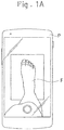
Fig. 1A shows a state where an image of a user's foot is being captured to obtain the user's foot shape data for a last according to one embodiment of the present invention. -
Fig. 1B is a perspective view of the last. -
Fig. 1C shows some of a plurality of blocks into which the last is disassembled. -
Fig. 2A is a top side perspective view showing a schematic configuration of the last. -
Fig. 2B is a bottom side perspective view showing a schematic configuration of the last. -
Fig. 3A is a perspective view showing an example configuration of a block. -
Fig. 3B is a vertical cross-sectional view showing an example configuration of a block. -
Fig. 3C is a perspective view showing examples of some blocks respectively having different shapes. -
Fig. 4 is a bottom side perspective view showing a schematic configuration of a last according to another embodiment of the present invention, the last having a hollow portion thereinside. For ease of viewing, the bottom portion of the last is illustrated by the dark-shaded area while the internal surface of the hollow portion is illustrated by the light-shaded area. -
Fig. 5 is a vertical cross-sectional view showing a schematic configuration of a last according to another embodiment of the present invention, the last having a central part and a peripheral part. -
Fig. 6 is a vertical cross-sectional view showing a schematic configuration of a last according to another embodiment of the present invention, the last having a central part and a peripheral part, and the last being divided into a fore portion and a hind portion. -
Fig. 7 is a side view showing a part of a combination of large and small blocks for a last according to another embodiment of the present invention. -
Fig. 8 is a perspective view showing a configuration in which a cover part is provided on an aggregate of a plurality of blocks, as a last according to another embodiment of the present invention. -
Fig. 9 is a side view showing a schematic configuration of a last in which a base part is combined with an aggregate of a plurality of blocks, according to another embodiment of the present invention. -
Fig. 10 is a side view showing a state where an unshaped upper is placed on the last (with its shape schematically shown) and subjected to steam-heating in a heating box. -
Fig. 11 is a side view showing a relationship between a forefoot portion (shown by solid line) and a structure of human foot anatomy (shown by two-dotted chain line). -
Fig. 12 is a perspective view showing a last according to another embodiment of the present invention. -
Fig. 13A is a perspective view showing an aggregate of a plurality of beads that are connected together in an annular form and constitute the last inFig. 12 . -
Fig. 13B is a perspective view of one of the plurality of beads constituting the last inFig. 12 . -
Fig. 13C is a perspective view showing an example of another form of the bead. - An embodiment of the present invention will be exemplified with reference to the drawings. Hereinafter, regarding the term representing the direction "inward and outward direction", the inward direction is a direction toward a foot of a shoe wearer, and the outward direction is a direction toward the outside of the shoe. Further, when a description is given below on a shoe upper 2 before and after being shaped, the shoe upper 2 before being shaped can be referred to as an unshaped upper 2A while the shoe upper 2 after being shaped can be referred to as a shaped upper 2B for separate identification of the respective states.
- A last (shoe last) 1 of this embodiment is mainly not a last for shoes for mass production, but a custom-made last 1 tailored to a user's foot F. However, the present invention does not intend to completely deny its application to a last for shoes for mass production, but can be applicable thereto. The last 1 can be produced at a shoe retailer, or can be produced at a factory located away from the retailer by transmission and reception of block joining data and data on a user's foot using a communication device, as will be described later. As shown in
Fig. 2A andFig. 2B , the last 1 of this embodiment has at least an outer peripheral portion (i.e., a portion coming into contact with the shoe upper 2 when the shoe upper 2 is shaped) including an aggregate of the plurality ofblocks 11. In this embodiment, the last 1 includes abody 12 composed of the aggregate of the plurality ofblocks 11. The aggregate of the plurality ofblocks 11 is formed by joining the plurality ofblocks 11 together by a human hand or a robot hand. The shoe upper 2 is, for example, formed of fabric, and in this embodiment formed of fabric composed of a heat-shrinkable fiber sheet. - As shown in
Fig. 1C andFig. 3A , each of the plurality ofblocks 11 of this embodiment has a cubic shape identical to each other. The material of theblock 11 is not particularly limited, but can be any material such as a metal, a magnetic body, a resin, ceramic, timber, or paper. Theblock 11 can be solid, but for example can be hollow inside as shown inFig. 3B , in terms of saving the weight of the last 1 composed of the aggregate of the plurality ofblocks 11. In the case where the same material is used, thehollow block 11 can have a smaller weight than that of thesolid block 11. The shape of theblock 11 is not limited to the cubic shape as in this embodiment, and can be a rectangular parallelepiped shape (seeFig. 7 ), a truncated square pyramid shape, a wedge shape (i.e., a triangular shape in cross section), or a shape having a curved surface as shown inFig. 3C . Theblock 11 having the curved surface is suitable for being arranged on the outermost part of the last 1 to obtain a smooth finish on the outer peripheral surface of thebody 12. This configuration allows the surface of the last 1 to have a curved surface. In order to enable oneblock 11 to be stacked on anotherblock 11, the surface of the oneblock 11 abutting the surface of the anotherblock 11 at the time of the stacking is preferably a surface suitable for the stacking, such as a flat surface. The plurality ofblocks 11 are not necessarily arranged tightly without a clearance, but may be arranged with a clearance formed between each adjacent two of the plurality ofblocks 11. The clearance may be provided on the outermost part of the last 1. - The plurality of
blocks 11 are configured to be joinable together and separable from each other. As a joining device, various devices can be used, such as a recess and projection fitting device or a magnet. As shown inFig. 12 andFig. 13A , awire 113 can be used as the joining device for connecting together a plurality ofbeads 11a, which serve as the plurality ofblocks 11, into an annular form. In the example shown inFig. 3A , a recess and projectionfitting device 111 is provided on each surface of the cubic block 11 (not shown in other Figures). The recess and projectionfitting device 111 can be, for example as illustrated, a combination of aprojection 111a projecting from a surface of thecubic block 11 and arecess 111b such as a through hole formed in another surface of thecubic block 11. Each adjacent twoblocks 11 can be joined together when aprojection 111a of one of the each adjacent twoblocks 11 is fitted into arecess 111b of theother block 11. In the case where magnets are used although not shown, the magnets provided on the opposed surfaces of each adjacent twoblocks 11 need to have opposite polarity to each other, so as to be attracted to each other. Alternatively, the configuration needs to be such that a surface of one of the each adjacent twoblocks 11 has a magnet while a surface of theother block 11 has a magnetic body (steel) that attracts the magnet. - Each of the plurality of
blocks 11 can have at least an outer peripheral surface formed of a material of high heat conductivity. For example, the outer peripheral surface can be a surface with a metal (e.g. an aluminum alloy) exposed. In this case, the surface of the metal material may be exposed to the outer peripheral surface, or a metal layer may be formed on the outer peripheral surface by plating or coating. The material of high heat conductivity is used to form the outer peripheral surface, which is a portion directly in contact with the shoe upper 2 unless acover part 15 is provided on abody 12 of the last 1 as will be described later. This configuration allows heat to be easily transferred to the shoe upper 2 particularly in the case where the shoe upper 2 having heat-shrinkability is shaped. - The plurality of
blocks 11 may have different shapes. In this case, the plurality ofblocks 11 have different sizes, as shown, for example, inFig. 7 . Among these, relatively large blocks in this embodiment are constituted by three kinds, namely: blocks 11L1 having a long rectangular parallelepiped shape; blocks 11L2 having a short rectangular parallelepiped shape; and blocks 11L3 having a cubic shape. The number of kinds of blocks is not particularly limited, and there may be two or more kinds (at least one kind each of relatively large blocks and relatively small blocks). The shapes of the individual blocks 11 to be combined are not particularly limited, either. As shown inFig. 7 , the relatively large blocks 11L1 to 11L3 can be arranged on an inner side of thebody 12 while relativelysmall blocks 11S can be arranged on an outer side thereof. This configuration allows the large blocks 11L1 to 11L3 to be used for roughly shaping the inner side of thebody 12, and then allows thesmall blocks 11S to be used for finely shaping the outer side of thebody 12. Thus, thebody 12 can be efficiently shaped as compared with, for example, the case where thebody 12 is shaped using only thesmall blocks 11S. Further, thesmall blocks 11S arranged on the outer side of thebody 12 allow the last 1 to be more finely shaped than the large blocks 11L1 to 11L3. - Another example of the case where the plurality of
blocks 11 have different shapes can be such that the relativelysmall blocks 11S are arranged at a portion of the last 1 corresponding to a forefoot portion of a user's foot, the shape of which is likely to vary by user, while the relatively large blocks 11L1 to 11L3 are arranged at other portions. Still another example may be such that the relativelysmall blocks 11S are arranged around a portion of the last 1 corresponding to a wearing opening of the shoe upper 2 while the relatively large blocks 11L1 to 11L3 are arranged at other portions. Each of these examples may be combined with the aforementioned configuration in which the relatively large blocks 11L1 to 11L3 are arranged on the inner side of thebody 12 while the relativelysmall blocks 11S are arranged on the outer side thereof. - The "forefoot portion" herein is intended to be a portion of the human (wearer's) foot anatomy as encircled in
Fig. 11 , that is, an area from theproximal phalanges B 1 of the toes (the middle phalanx B2 for the fifth toe) to the anterior parts of the talus B3 and the calcaneus B4. A portion of the shoe upper 2 corresponding to the forefoot portion FP is an important portion because it gives great influence on the feeling of wearing or the athletic performance of the wearer. Thus, forming the forefoot portion FP by arranging the relativelysmall blocks 11S can produce a significant effect responsive to the aforementioned influence. The "wearing opening" is intended to be an opening of a shoe through which the wearer places his or her foot into or out of the shoe. The wearing opening is also an important portion because it has great influence on the feeling of wearing of the wearer. Thus, forming the portion of the wearing opening by arranging the relativelysmall blocks 11S can produce a significant effect responsive to the aforementioned influence. - In the case where the plurality of
blocks 11 have different shapes, eachblock 11 can have anidentifier 112 for allowing its shape to be externally identifiable, as shown inFig. 3 . When eachblock 11 has theidentifier 112, it becomes easy to sort theblocks 11 by shape (including size) or join together theblocks 11 having the same shape. Theidentifier 112 can also be used to identify the position or orientation of theblock 11, such as a direction in which a stacking surface of theblock 11 faces. Examples of theidentifier 112 include an IC chip and a two-dimensional code. Further, theidentifier 112 can be a color, a surface pattern, or a partial change in shape (e.g., a recess or a projection, a notch, a through hole) that is image-identifiable (i.e., by human visual observation or mechanical observation). - The last 1 configured as above can be disassembled back into the plurality of
individual blocks 11 after being used for shaping the shoe upper 2. Thereafter, the plurality ofblocks 11 can be reassembled to form the aggregate. This allows the last 1 to be reusable. The last 1 is not essentially disassembled into the individual blocks 11, and may be disassembled into a plurality of aggregates each formed of a plurality ofblocks 11 connected together. - The last 1 may be solid, but is preferably hollow inside, as shown in
Fig. 4 orFig. 5 . In the case where the last 1 is formed to be hollow, thebody 12 is formed of an aggregate of a plurality ofblocks 11 that surrounds aninternal space 1a, which corresponds to a hollow portion of the last 1. The example shown inFig. 4 orFig. 5 has theinternal space 1a that is open on its bottom side, without limitation thereto. Theinternal space 1a may be closed by a plurality ofblocks 11 arranged over the entire periphery of theinternal space 1a. The last 1 formed to be hollow can still ensure the strength by allowing thebody 11 to have a certain thickness, and thus has no functional problem. The last 1 formed to be hollow eliminates the necessity to arrangeblocks 11 in the center portion of the last 1, and can thus reduce the number ofblocks 11 constituting the last 1 by the number equivalent to the volume of an internal portion. The last 1 thus formed can save the material. This configuration can also save the time required for forming the last 1 (shaping time). Further, this configuration can save the weight of the last 1, and therefore allows the last 1 to be easily handled. As described above, this configuration has various advantages. - As shown in
Fig. 5 , the last 1 can include acentral part 13 and aperipheral part 14. Thecentral part 13 is formed in advance as a core member of the last 1. Thecentral part 13 may be solid or hollow. Thecentral part 13 formed to be hollow as shown inFig. 5 can save the weight of the last 1. Theperipheral part 14 is formed on an outer peripheral portion of thecentral part 13. Theperipheral part 14 is constituted by an aggregate of a plurality ofblocks 11. That is, in this configuration, thecentral part 13 is positioned in theinternal space 1a in the aforementioned configuration. The last 1 configured as above can reduce the number ofblocks 11 constituting the last 1 by the number equivalent to the volume of the internal portion, and can thus save the time required for forming the last 1(shaping time), similar to the aforementioned configuration. This configuration can reduce the amount of theblocks 11 used for forming the last 1 as compared with the configuration in which the last 1 is solid and entirely formed in a uniform manner. In the case where shoes are produced at a factory, use of thecentral part 13 as a core material allows only thecentral part 13, which is slightly smaller than the last 1, to be stored in the factory for a long period of time. Thus, the number ofcentral parts 13 stored per specific space can increase as compared with the case where the lasts 1 are entirely stored, and the storage space can be thereby saved. Even when the lasts 1 of different sizes are required, theircentral parts 13 can be made to have the same shape (size) so that the necessity to store the lasts 1 by size is eliminated. That is, thecentral parts 13 can have the same shape (size) irrespective of who are the shoe wearers when thecentral parts 13 are constituted respectively by portions having a common volume regardless of the shoe wearer's physical constitution. - The
central part 13 may have a fixed shape as shown inFig. 5 , or may be, for example, configured to have a screw or the like to allow the dimension in a front and back direction (longitudinal direction) of thecentral part 13 to be adjustable, like a shoe tree (sometimes called a "shoe keeper" in Japan). Specifically, as shown inFig. 6 , thecentral part 13 can be configured to be divided into afront part 13a provided on the front side and aback part 13b provide on the back side, with reference to the front and back direction of a shoe when worn. In this configuration, thecentral part 13 can further include anaxial member 13c provided with a screw, a spring, or the like, theaxial member 13c arranged between thefront part 13a and theback part 13b so as to be capable of extending and shortening in the front and back direction and being fixed at a desired length. This configuration allows thebody 12 of the last 1 to be divided into aforefoot part 12a and ahindfoot part 12b. A portion (midfoot part) between theforefoot part 12a and thehindfoot part 12b may be constituted only by theaxial member 13c with noblock 11 provided therein as shown inFig. 6 , or may have a plurality ofblocks 11 provided after the extended or shortened state of theaxial member 13c is fixed. - In the case where the last 1 includes the
central part 13, theperipheral part 14 can be formed of a material of higher heat conductivity than that of thecentral part 13. For example, the plurality ofblocks 11 constituting theperipheral part 14 can be formed of metal (e.g., an aluminum alloy) while thecentral part 13 can be formed of a heat-resistant resin (for example a resin resistant to heat of 200 °C or higher). This configuration causes theperipheral part 14 of the last 1 to be heated when the shoe upper 2 is heated for shaping (seeFig. 10 ), and thereby allows the shoe upper 2 to be heated also from the side of the last 1 (that is, the unshaped upper 2A is to be heated from both inside and outside). This configuration can thus shorten the heating time compared to the case where heating is performed only from outside, and allows the shoe upper 2 to be shaped efficiently (i.e., within a short time). - The aggregate of the plurality of
blocks 11 constituting the outer peripheral portion may be at least partially covered with a sheet-shaped or a plate-shapedcover part 15 from outside. The material of thecover part 15 is not particularly limited, and can be, for example, the same material as that of theblocks 11. Thecover part 15 can, for example, have a shape having a curved surface, as shown inFig. 8 . Thecover part 15 configured as above is attached to thebody 12 to fill the steps or gaps among the aggregate of the plurality ofblocks 11, the steps or gaps being caused by connecting each adjacent blocks 11. That is, thecover part 15 can arrange the outer peripheral shape of the last 1. This configuration allows the shoe upper 2 to be shaped into a desired form. Thecover part 15 may be of a single piece, or may be constituted by a plurality of pieces combined and integrated together. - As shown in
Fig. 9 , the last 1 may include a plate-shapedbase part 16, and an aggregate of a plurality ofblocks 11 arranged on the upper side of thebase part 16. Thebase part 16 functions to shape a lower part of the shoe upper 2. The use of thebase part 16 allows the lower part of the shoe upper 2 to be shaped into a constant form, as compared with the configuration in which the aggregate of the plurality ofblocks 11 is exposed on the bottom side of the last 1. This configuration allows the lower part of the shoe upper 2 to be shaped into a desired shape in conformity with the shape of a sole (specifically, the shape of the upper surface of a sole). In order to form the lower part of the shoe upper 2 in conformity to the shape of the sole, the shape of the lower part (lower surface) of the last 1 is naturally determined. Therefore, the last 1 can be formed more efficiently when the lower part of the last 1 is formed by, for example, using thebase 16 formed of a single, unified piece than when it is formed by arranging a plurality ofblocks 11. -
Fig. 9 is a simplified view illustrating the configuration of the last 1 provided with thebase part 16, and the form of thebase part 16 is not limited to the illustrated form. Since the shoe upper 2 is formed to conform to the shape of the upper surface of a midsole, thebase part 16 generally has a relatively complicated plate shape rather than a flat plate shape. Thus, thebase part 16 may have an uneven surface to, for example, allow its upper surface to integrally have theblocks 11. Further, the bottom surface of thebase part 16 is generally constituted by an uneven surface or a curved surface, rather than a flat surface. - Next, a method for producing the last 1 will be described. The last 1 is formed by joining the plurality of
blocks 11 together into the aggregate. Thus, the last 1 can be easily formed without use of a forming mold as compared with, for example, the case where the last is formed of a resin material. - Before the last 1 is formed, a data acquiring step of acquiring the user's foot shape data, and a data generating step of generating block joining data from the user's foot shape data acquired are performed. Thereafter, a last forming step of joining the plurality of
blocks 11 together based on the generated block joining data is performed. Performing these steps enables forming the custom-made last 1 tailored to the user's foot F. - The block joining data is created based on the user's foot shape data, which is individually generated for each of a plurality of users. The block joining data thus generated allows the shoe upper 2 to be finely customized for each user. The block joining data includes information on how the
blocks 11 are to be stacked on each other. In the case where the plurality ofblocks 11 having different shapes (including sizes) are used, the block joining data includes information on which shape (size) of theblocks 11 are used and at which position of the last 1 thoseblocks 11 are arranged. - The last forming step is performed by joining the plurality of
blocks 11 by a human hand or a robot hand. In the case where the last forming step is performed particularly by a robot hand, a sensor or a camera reads theidentifier 112 of eachblock 11, and a controller configured to control the robot hand thereby recognizes the shape (size) and position or orientation of theblock 11. In the case where thecover part 15 is provided as shown inFig. 8 , thecover part 15 is attached in the last forming step to at least partially cover the aggregate of the plurality ofblocks 11. In the case where thebase part 16 is provided as shown inFig. 9 , the aggregate of the plurality ofblocks 11 is formed on the upper side of thebase part 16 in the last forming step. - The user's foot shape data refers to, for example, measurement data of each part of the user's foot F generated from image data obtained by capturing an image of the user's foot F as shown in
Fig. 1A . Thus, the user's foot shape data can be easily generated using, for example, a digital camera or a smartphone P (seeFig. 1A ). In the case, for example, where the smartphone P is used, the foot shape data can be generated based on the image data by software that is installed in advance in the smartphone P. The foot shape data can also be created by calculation using both the captured image data and data owned by a shoemaker in their server. - The image data can be acquired at the user's home or at a retailer (dealer) the user visits. In this case, the image data is transmitted to the server of a shoemaker and the foot shape data is generated at a factory of the shoemaker, so that the lasts 1 and shoes conforming thereto can be subsequently produced at the factory. It is also possible to acquire the image data at a retailer and produce the lasts 1 and shoes conforming thereto at the retailer. It is of course possible to produce the lasts 1 and shoes conforming thereto respectively at different places. The retailer is not limited to a fixed store but may be a mobile store using a car or a trailer.
- A disassembling step is performed when the last 1 is no longer required after being used for shaping the shoe upper 2. In the disassembling step, the aggregate of the plurality of
blocks 11 constituting the last 1 after being used is disassembled into individual blocks 11 (seeFig. 1C ) or into small-unit aggregates each having a smaller number ofblocks 11 than that of the aforementioned aggregate. The disassembling step can be performed by a human hand or a robot hand. A device configured to unjoin theblocks 11 by applying impact on the aggregate of the plurality ofblocks 11 or by demagnetizing theblocks 11 in the case where they are joined together by magnetic force can also be used. Performing the disassembling step as described above allows the plurality of disassembledblocks 11 or the small-unit aggregates to be reused to produce a new last 1. The last 1 after being used can be thus reused as a last 1 for another user. - Next, a method for producing the shoe upper 2 using the last 1 will be briefly described. For example, a material of the shoe upper 2 (i.e., the unshaped upper 2A) composed of a fiber sheet including heat-shrinkable yarns is prepared. Then, carried out are a first shaping step of placing the unshaped upper 2A on the last 1, and a second shaping step of shaping the unshaped upper 2A in conformity with the shape of the last 1 by heating to obtain the shaped upper 2B as shown in
Fig. 10 . A steam heating means is used as a heating means in the second shaping step. As schematically shown inFig. 10 , for example, the unshaped upper 2A is placed in aheating box 31, and heated with high-temperature steam 32 discharged from the inner surface of theheating box 31. This steam heating allows the unshaped upper 2A to be entirely and uniformly heated. This configuration allows the unshaped upper 2A to be uniformly deformed in conformity with the shape of the last 1 to obtain the shaped upper 2B. In the second shaping step, hot-air heating, hot water heating, or the like can be used other than the steam heating. Further, the unshaped upper 2A can be heated not entirely but partially. - Performed after the second shaping step is a sole attaching step, in which the shaped upper 2B is attached to a separately prepared sole by, for example, adhesive. Other than adhesive, heat fusion bonding, for example, can be applied to perform the sole attaching step simultaneously with the second shaping step. In this case, the heat fusion bonding can be efficiently performed using the last 1 having the
central part 13 formed of a material of high heat conductivity (for example, a metal such as aluminum, copper, or stainless steel). Forming a shoe tongue, trimming a wearing opening, making eyelets for passing shoelace therethrough, attaching decoration members and tags, printing a logo, and attaching an insole can be performed as appropriate, during any of the aforementioned steps or after all the steps. - Hereinafter, the configurations and operational effects according to the embodiment of the present invention will be summarized. Provided in this embodiment is a last 1 for shaping a shoe upper 2, including: at least an outer peripheral portion including an aggregate of a plurality of
blocks 11, the plurality ofblocks 11 being joinable together and separable from each other. - This configuration allows the aggregate to be disassembled into the individual blocks 11 after the shoe upper 2 is shaped, thereby allowing the last 1 to be reusable.
- The last 1 can be hollow inside.
- This configuration can reduce the number of
blocks 11 constituting the last 1 by the number equivalent to the volume of an internal portion of the last 1, thereby enabling the shaping time of the last 1 to be shortened. - The last 1 can include: a
central part 13 formed in advance as a core; and aperipheral part 14 that is constituted by the aggregate of the plurality ofblocks 11 formed on an outer peripheral portion of thecentral part 13. - This configuration can reduce the number of
blocks 11 included in the last 1, thereby enabling the shaping time to be shortened. - Each of the plurality of
blocks 11 can have at least an outer peripheral surface formed of a material of high heat conductivity. - This configuration allows heat to be easily transferred to the shoe upper 2 particularly in the case where the shoe upper 2 having heat-shrinkability is shaped.
- The configuration can be such that the plurality of
blocks 11 have a plurality of different shapes, and that each of the plurality ofblocks 11 has anidentifier 112 for allowing a shape of the each of the plurality ofblocks 11 to be externally identifiable. - This configuration makes it easy to sort the plurality of
blocks 11 by shape or to join together theblocks 11 having the same shape. - The configuration can be such that the plurality of
blocks 11 have a plurality of different sizes, and that relatively large blocks 11L1 to 11L3 are arranged on an inner side of the last 1 while relativelysmall blocks 11S are arranged on an outer side thereof. - This configuration allows the large blocks 11L1 to 11L3 to be used for roughly shaping the inner side of the last 1, and then allows the
small blocks 11S to be used for finely shaping the outer side of the last 1. - Each of the plurality of
blocks 11 can be hollow inside. - This configuration can save the weight of the last 1.
- The aggregate of the plurality of
blocks 11 can have an outer peripheral portion at least partially covered by a sheet-shaped or a plate-shapedcover part 15 from outside. - This configuration allows the
cover part 15 to be used for arranging the outer peripheral shape of the last 1. - The configuration can be such that the aggregate of the plurality of
blocks 11 is provided on an upper side of a plate shapedbase part 16 for shaping a lower part of the shoe upper 2. - This configuration allows the lower part of the shoe upper 2 to be shaped into a constant shape by using the
base part 16. - Provided in this embodiment is a method for producing a last 1 for shaping a shoe upper 2, including: forming the last 1 by joining a plurality of
blocks 11 together to form an aggregate. - This configuration allows the last 1 to be easily formed without a use of a forming mold.
- The method for producing the last 1 can include: a data acquiring step of acquiring a user's foot shape data; a data generating step of generating block joining data from the user's foot shape data; and a last forming step of joining the plurality of
blocks 11 together based on the block joining data. - The production method thus configured allows the last 1 to be formed tailored to the user's foot.
- The method for producing the last 1 can include creating the block joining data based on the user's foot shape data individually generated for each of a plurality of users.
- The production method thus configured allows the shoe upper 2 to be customized for each user.
- The user's foot shape data can be generated from image data obtained by capturing an image of the user's foot.
- The production method thus configured allows the foot shape data to be easily generated using, for example, a digital camera or a smartphone P.
- The method for producing the last 1 can further include: a disassembling step of disassembling the last 1 after being used into the plurality of
blocks 11. - The production method thus configured allows the last 1 after being used to be reusable as a last 1 for another user.
- Provided in the aforementioned embodiment is a method for producing a shoe upper 2, including: a first shaping step of placing an unshaped upper 2A on the last 1, the unshaped upper 2A composed of a fiber sheet including heat-shrinkable yarns; and a second shaping step of shaping the unshaped upper 2A in conformity with the shape of the last 1 by heating to obtain a shaped upper 2B.
- The production method thus configured allows the shoe upper 2 to be produced using a reusable last 1.
- The present invention has been described by taking an embodiment, but the description is merely an exemplification. The last 1, the method for producing the last 1, and the method for producing the shoe upper 2, according to the present invention, are not limited to the aforementioned embodiment. Thus, various modifications can be made for the last 1, the method for producing the last 1, and the method for producing the shoe upper 2, according to the present invention, without departing from a gist of the present invention. The modifications include, for example, partially replacing or partially omitting a plurality of elements constituting the aforementioned embodiments, and combining an element pertaining to an embodiment with an element pertaining to another embodiment as appropriate. The modifications also include combining matters pertaining to common technical knowledge regarding the last 1, the method for producing the last 1, and the method for producing the shoe upper 2.
- For example, the configuration can be such that each
block 11 is acylindrical bead 11a having a throughhole 114 as shown inFig. 13B , or is aspherical bead 11b having a throughhole 114 as shown inFig. 13C . For example, a plurality ofcylindrical beads 11a are connected together with awire 113 passing through the throughholes 114 of therespective beads 11a to form anannular body 17 as shown inFig. 13A . Thewire 113 may be a cord capable of retaining its shape, such as metal wire, or may be a soft cord such as thread. - As shown in
Fig. 12 , a plurality ofannular bodies 17 each formed to conform to the shape of the corresponding portion of the last 1 are combined to form the last 1. In the example shown inFig. 12 , the hind portion of the last 1 has a constant form, and the fore portion thereof has abase part 18 around which theannular bodies 17 can be wound. A combination of thebase part 18 and each block 11 (eachbead 11a in this case) allows a specific portion of the last 1 to be easily formed in conformity to the shape of the corresponding portion of the user's foot F. Although not shown, theannular bodies 17 may be wound around the hind portion of the last 1 (i.e., a portion corresponding to the heel of the user's foot F), or may be wound around the entire portion of the last 1. - The last 1 may be formed to entirely conform to the shape of the user's foot F, but may be formed to have a specific portion having a desired dimension inconsistent with the shape of the user's foot F for design or functional reasons.
- The method for producing the shoe upper 2 is not limited to the aforementioned embodiment in which the fiber sheet including heat-shrinkable yarns are heat-shrunk, but various methods such as: knitting yarns to form fabric surrounding the last 1; or layering a material using a 3D printer can be employed.
Claims (15)
- A last for shaping a shoe upper, comprising:at least an outer peripheral portion comprising an aggregate of a plurality of blocks,the plurality of blocks being joinable together and separable from each other.
- The last according to claim 1, wherein the last is hollow inside.
- The last according to claim 1 or 2, comprising: a central part formed in advance as a core; and a peripheral part that is constituted by the aggregate of the plurality of blocks formed on an outer peripheral portion of the central part.
- The last according to any one of claims 1 to 3, wherein each of the plurality of blocks has at least an outer peripheral surface formed of a material of high heat conductivity.
- The last according to any one of claims 1 to 4, wherein the plurality of blocks have a plurality of different shapes, and
each of the plurality of blocks has an identifier for allowing a shape of the each of the plurality of blocks to be externally identifiable. - The last according to any one of claims 1 to 5, wherein the plurality of blocks have a plurality of different sizes, and
relatively large blocks are arranged on an inner side of the last while relatively small blocks are arranged on an outer side thereof. - The last according to any one of claims 1 to 6, wherein each of the plurality of blocks is hollow inside.
- The last according to any one of claims 1 to 7, wherein the aggregate of the plurality of blocks has an outer peripheral portion at least partially covered by a sheet-shaped or a plate-shaped cover part from an outside.
- The last according to any one of claims 1 to 8, comprising: the aggregate of the plurality of blocks on an upper side of a plate-shaped base part for shaping a lower part of the shoe upper.
- A method for producing a last for shaping a shoe upper, comprising:
forming the last by joining a plurality of blocks together to form an aggregate. - The method for producing the last according to claim 10, comprising:
a data acquiring step of acquiring a user's foot shape data; a data generating step of generating block joining data from the user's foot shape data; and a last forming step of joining the plurality of blocks together based on the block joining data. - The method for producing the last according to claim 11, comprising:
creating the block joining data based on the user's foot shape data individually generated for each of the plurality of users. - The method for producing the last according to claim 12, comprising:
generating the user's foot shape data from image data obtained by capturing an image of the user's foot. - The method for producing the last according to any one of claims 10 to 13, further comprising: a disassembling step of disassembling the last after being used into the plurality of blocks.
- A method for producing a shoe upper, comprising:a first shaping step of placing an unshaped upper on the last according to any one of claims 1 to 9, the unshaped upper composed of a fiber sheet comprising heat-shrinkable yarns; anda second shaping step of shaping the unshaped upper in conformity with the shape of the last by heating to obtain a shaped upper.
Applications Claiming Priority (2)
| Application Number | Priority Date | Filing Date | Title |
|---|---|---|---|
| JP2019229047 | 2019-12-19 | ||
| JP2020084990A JP7125961B2 (en) | 2019-12-19 | 2020-05-14 | Last, manufacturing method of last, manufacturing method of shoe upper |
Publications (2)
| Publication Number | Publication Date |
|---|---|
| EP3838045A1 true EP3838045A1 (en) | 2021-06-23 |
| EP3838045B1 EP3838045B1 (en) | 2023-08-02 |
Family
ID=71266403
Family Applications (1)
| Application Number | Title | Priority Date | Filing Date |
|---|---|---|---|
| EP20182729.2A Active EP3838045B1 (en) | 2019-12-19 | 2020-06-26 | Last, method for producing last, and method for producing shoe upper |
Country Status (3)
| Country | Link |
|---|---|
| US (1) | US11622604B2 (en) |
| EP (1) | EP3838045B1 (en) |
| CN (1) | CN112998359A (en) |
Citations (7)
| Publication number | Priority date | Publication date | Assignee | Title |
|---|---|---|---|---|
| US1565057A (en) * | 1924-03-10 | 1925-12-08 | Chappell Frederick William | Last for boots, shoes, and the like |
| US20070033750A1 (en) * | 2005-08-12 | 2007-02-15 | Nike, Inc. | Custom fit system with adjustable last and method for custom fitting athletic shoes |
| US20160206049A1 (en) | 2015-01-16 | 2016-07-21 | Nike, Inc. | Shape Memory Polymer Footwear Last |
| US20180014609A1 (en) | 2014-12-10 | 2018-01-18 | Nike, Inc. | Portable manufacturing system for articles of footwear |
| US20180237964A1 (en) * | 2016-11-09 | 2018-08-23 | Nike, Inc. | Knit textiles and uppers, and processes for making the same |
| CN109732913A (en) | 2019-01-22 | 2019-05-10 | 东莞市原力无限打印科技有限公司 | A kind of 3D printing manufacturing method of shoe tree |
| WO2020077093A1 (en) * | 2018-10-11 | 2020-04-16 | The North Face Apparel Corp. | Modular last |
Family Cites Families (12)
| Publication number | Priority date | Publication date | Assignee | Title |
|---|---|---|---|---|
| US2560992A (en) * | 1946-10-24 | 1951-07-17 | Vulcan Corp | Method of making last blocks |
| CN204742836U (en) * | 2015-07-27 | 2015-11-11 | 福建省宝树鞋楦有限公司 | Electromagnetism concatenation formula shoe tree |
| JP6784408B2 (en) | 2015-11-06 | 2020-11-11 | 株式会社ドリーム・ジーピー | How to make a wooden pattern |
| IT201700047089A1 (en) | 2017-05-02 | 2018-11-02 | Else Corp S R L | Method and modification system for shoe shapes based on the application of additional patches |
| CN207444401U (en) | 2017-10-13 | 2018-06-05 | 探路者控股集团股份有限公司 | A kind of shoe tree |
| CN108158134A (en) * | 2018-02-23 | 2018-06-15 | 新百丽鞋业(深圳)有限公司 | Shoe tree |
| CN108428167A (en) * | 2018-02-24 | 2018-08-21 | 新百丽鞋业(深圳)有限公司 | A kind of control method and control system of shoes customization |
| CN208959314U (en) * | 2018-09-19 | 2019-06-11 | 美科科技(北京)有限公司 | Basic building blocks, control mould group and intelligent building blocks |
| CN209106400U (en) | 2018-10-29 | 2019-07-16 | 陕西科技大学 | A kind of adjustable shoe tree |
| CN109224477A (en) * | 2018-11-08 | 2019-01-18 | 艺识流(北京)科技有限公司 | Modular programmable, intelligent building blocks |
| CN109864394A (en) * | 2019-02-20 | 2019-06-11 | 先临三维科技股份有限公司 | The manufacturing method of Combined shoe last and its Combined shoe last being prepared |
| CN112674432A (en) * | 2019-10-18 | 2021-04-20 | 株式会社爱世克私 | Shoe tree, manufacturing method of shoe tree and manufacturing method of shoe upper |
-
2020
- 2020-06-10 CN CN202010525341.6A patent/CN112998359A/en active Pending
- 2020-06-26 EP EP20182729.2A patent/EP3838045B1/en active Active
- 2020-06-29 US US16/915,245 patent/US11622604B2/en active Active
Patent Citations (7)
| Publication number | Priority date | Publication date | Assignee | Title |
|---|---|---|---|---|
| US1565057A (en) * | 1924-03-10 | 1925-12-08 | Chappell Frederick William | Last for boots, shoes, and the like |
| US20070033750A1 (en) * | 2005-08-12 | 2007-02-15 | Nike, Inc. | Custom fit system with adjustable last and method for custom fitting athletic shoes |
| US20180014609A1 (en) | 2014-12-10 | 2018-01-18 | Nike, Inc. | Portable manufacturing system for articles of footwear |
| US20160206049A1 (en) | 2015-01-16 | 2016-07-21 | Nike, Inc. | Shape Memory Polymer Footwear Last |
| US20180237964A1 (en) * | 2016-11-09 | 2018-08-23 | Nike, Inc. | Knit textiles and uppers, and processes for making the same |
| WO2020077093A1 (en) * | 2018-10-11 | 2020-04-16 | The North Face Apparel Corp. | Modular last |
| CN109732913A (en) | 2019-01-22 | 2019-05-10 | 东莞市原力无限打印科技有限公司 | A kind of 3D printing manufacturing method of shoe tree |
Also Published As
| Publication number | Publication date |
|---|---|
| US20210186163A1 (en) | 2021-06-24 |
| US11622604B2 (en) | 2023-04-11 |
| CN112998359A (en) | 2021-06-22 |
| EP3838045B1 (en) | 2023-08-02 |
Similar Documents
| Publication | Publication Date | Title |
|---|---|---|
| JP7206396B2 (en) | Heel structure with locating pegs and method of manufacturing footwear | |
| KR101804031B1 (en) | System and method for forming an article | |
| EP3808202B1 (en) | Last, method for producing last, and method for producing shoe upper | |
| KR101257646B1 (en) | Method of customizing an article and apparatus | |
| WO2021238856A1 (en) | Production method for customized insole and selling method | |
| US11547181B2 (en) | Last, method for manufacturing last, and method for manufacturing footwear upper | |
| CN112449576A (en) | Method and system for obtaining foot analysis data | |
| EP3838045A1 (en) | Last, method for producing last, and method for producing shoe upper | |
| US416861A (en) | scafe | |
| JP7125961B2 (en) | Last, manufacturing method of last, manufacturing method of shoe upper | |
| WO2021106275A1 (en) | Method for manufacturing custom order shoes | |
| US8732881B2 (en) | Method for manufacturing detachable zipper shoe | |
| EP3827690A1 (en) | Shoe and shoe production method | |
| TWM506501U (en) | Shoe pad with gradient support structure | |
| JP2021175495A (en) | Shoe last, method for manufacturing shoe last and method for manufacturing shoe upper | |
| US9549587B1 (en) | Heat molded footwear and method | |
| CN108652136A (en) | The three-dimensional kenel of vamp forms in the method and its structure of stereo shoe-vamp plane materiel | |
| JP7125793B2 (en) | Manufacturing method of custom order shoes | |
| JP7005764B2 (en) | Shoe upper and manufacturing method of shoe upper | |
| TWM551002U (en) | Three-dimensional vamp formation structure for composite layer type three-dimensional shoe body | |
| KR101308291B1 (en) | Assistance shoes heel manufacturing mold and assistance shoes heel manufacturing methods | |
| KR20220057779A (en) | Customized shoe manufacturing system using untact 3D scanner and modifled moulding frame | |
| CN108656589A (en) | The method and its structure of composite bed type solid forming shoe body | |
| JP5933772B1 (en) | Shoes manufacturing method | |
| KR101578468B1 (en) | shoe sole having pressure controlable air block and shoe having the same |
Legal Events
| Date | Code | Title | Description |
|---|---|---|---|
| PUAI | Public reference made under article 153(3) epc to a published international application that has entered the european phase |
Free format text: ORIGINAL CODE: 0009012 |
|
| STAA | Information on the status of an ep patent application or granted ep patent |
Free format text: STATUS: THE APPLICATION HAS BEEN PUBLISHED |
|
| AK | Designated contracting states |
Kind code of ref document: A1 Designated state(s): AL AT BE BG CH CY CZ DE DK EE ES FI FR GB GR HR HU IE IS IT LI LT LU LV MC MK MT NL NO PL PT RO RS SE SI SK SM TR |
|
| STAA | Information on the status of an ep patent application or granted ep patent |
Free format text: STATUS: EXAMINATION IS IN PROGRESS |
|
| 17P | Request for examination filed |
Effective date: 20211209 |
|
| 17Q | First examination report despatched |
Effective date: 20211221 |
|
| RBV | Designated contracting states (corrected) |
Designated state(s): AL AT BE BG CH CY CZ DE DK EE ES FI FR GB GR HR HU IE IS IT LI LT LU LV MC MK MT NL NO PL PT RO RS SE SI SK SM TR |
|
| GRAP | Despatch of communication of intention to grant a patent |
Free format text: ORIGINAL CODE: EPIDOSNIGR1 |
|
| STAA | Information on the status of an ep patent application or granted ep patent |
Free format text: STATUS: GRANT OF PATENT IS INTENDED |
|
| INTG | Intention to grant announced |
Effective date: 20230316 |
|
| GRAS | Grant fee paid |
Free format text: ORIGINAL CODE: EPIDOSNIGR3 |
|
| GRAA | (expected) grant |
Free format text: ORIGINAL CODE: 0009210 |
|
| STAA | Information on the status of an ep patent application or granted ep patent |
Free format text: STATUS: THE PATENT HAS BEEN GRANTED |
|
| AK | Designated contracting states |
Kind code of ref document: B1 Designated state(s): AL AT BE BG CH CY CZ DE DK EE ES FI FR GB GR HR HU IE IS IT LI LT LU LV MC MK MT NL NO PL PT RO RS SE SI SK SM TR |
|
| REG | Reference to a national code |
Ref country code: GB Ref legal event code: FG4D |
|
| REG | Reference to a national code |
Ref country code: CH Ref legal event code: EP |
|
| REG | Reference to a national code |
Ref country code: DE Ref legal event code: R096 Ref document number: 602020014789 Country of ref document: DE |
|
| REG | Reference to a national code |
Ref country code: IE Ref legal event code: FG4D |
|
| REG | Reference to a national code |
Ref country code: LT Ref legal event code: MG9D |
|
| REG | Reference to a national code |
Ref country code: NL Ref legal event code: MP Effective date: 20230802 |
|
| REG | Reference to a national code |
Ref country code: AT Ref legal event code: MK05 Ref document number: 1593602 Country of ref document: AT Kind code of ref document: T Effective date: 20230802 |
|
| PG25 | Lapsed in a contracting state [announced via postgrant information from national office to epo] |
Ref country code: GR Free format text: LAPSE BECAUSE OF FAILURE TO SUBMIT A TRANSLATION OF THE DESCRIPTION OR TO PAY THE FEE WITHIN THE PRESCRIBED TIME-LIMIT Effective date: 20231103 |
|
| PG25 | Lapsed in a contracting state [announced via postgrant information from national office to epo] |
Ref country code: IS Free format text: LAPSE BECAUSE OF FAILURE TO SUBMIT A TRANSLATION OF THE DESCRIPTION OR TO PAY THE FEE WITHIN THE PRESCRIBED TIME-LIMIT Effective date: 20231202 |
|
| PG25 | Lapsed in a contracting state [announced via postgrant information from national office to epo] |
Ref country code: SE Free format text: LAPSE BECAUSE OF FAILURE TO SUBMIT A TRANSLATION OF THE DESCRIPTION OR TO PAY THE FEE WITHIN THE PRESCRIBED TIME-LIMIT Effective date: 20230802 Ref country code: RS Free format text: LAPSE BECAUSE OF FAILURE TO SUBMIT A TRANSLATION OF THE DESCRIPTION OR TO PAY THE FEE WITHIN THE PRESCRIBED TIME-LIMIT Effective date: 20230802 Ref country code: PT Free format text: LAPSE BECAUSE OF FAILURE TO SUBMIT A TRANSLATION OF THE DESCRIPTION OR TO PAY THE FEE WITHIN THE PRESCRIBED TIME-LIMIT Effective date: 20231204 Ref country code: NO Free format text: LAPSE BECAUSE OF FAILURE TO SUBMIT A TRANSLATION OF THE DESCRIPTION OR TO PAY THE FEE WITHIN THE PRESCRIBED TIME-LIMIT Effective date: 20231102 Ref country code: NL Free format text: LAPSE BECAUSE OF FAILURE TO SUBMIT A TRANSLATION OF THE DESCRIPTION OR TO PAY THE FEE WITHIN THE PRESCRIBED TIME-LIMIT Effective date: 20230802 Ref country code: LV Free format text: LAPSE BECAUSE OF FAILURE TO SUBMIT A TRANSLATION OF THE DESCRIPTION OR TO PAY THE FEE WITHIN THE PRESCRIBED TIME-LIMIT Effective date: 20230802 Ref country code: LT Free format text: LAPSE BECAUSE OF FAILURE TO SUBMIT A TRANSLATION OF THE DESCRIPTION OR TO PAY THE FEE WITHIN THE PRESCRIBED TIME-LIMIT Effective date: 20230802 Ref country code: IS Free format text: LAPSE BECAUSE OF FAILURE TO SUBMIT A TRANSLATION OF THE DESCRIPTION OR TO PAY THE FEE WITHIN THE PRESCRIBED TIME-LIMIT Effective date: 20231202 Ref country code: HR Free format text: LAPSE BECAUSE OF FAILURE TO SUBMIT A TRANSLATION OF THE DESCRIPTION OR TO PAY THE FEE WITHIN THE PRESCRIBED TIME-LIMIT Effective date: 20230802 Ref country code: GR Free format text: LAPSE BECAUSE OF FAILURE TO SUBMIT A TRANSLATION OF THE DESCRIPTION OR TO PAY THE FEE WITHIN THE PRESCRIBED TIME-LIMIT Effective date: 20231103 Ref country code: FI Free format text: LAPSE BECAUSE OF FAILURE TO SUBMIT A TRANSLATION OF THE DESCRIPTION OR TO PAY THE FEE WITHIN THE PRESCRIBED TIME-LIMIT Effective date: 20230802 Ref country code: AT Free format text: LAPSE BECAUSE OF FAILURE TO SUBMIT A TRANSLATION OF THE DESCRIPTION OR TO PAY THE FEE WITHIN THE PRESCRIBED TIME-LIMIT Effective date: 20230802 |
|
| PG25 | Lapsed in a contracting state [announced via postgrant information from national office to epo] |
Ref country code: PL Free format text: LAPSE BECAUSE OF FAILURE TO SUBMIT A TRANSLATION OF THE DESCRIPTION OR TO PAY THE FEE WITHIN THE PRESCRIBED TIME-LIMIT Effective date: 20230802 |
|
| PG25 | Lapsed in a contracting state [announced via postgrant information from national office to epo] |
Ref country code: ES Free format text: LAPSE BECAUSE OF FAILURE TO SUBMIT A TRANSLATION OF THE DESCRIPTION OR TO PAY THE FEE WITHIN THE PRESCRIBED TIME-LIMIT Effective date: 20230802 |
|
| PG25 | Lapsed in a contracting state [announced via postgrant information from national office to epo] |
Ref country code: SM Free format text: LAPSE BECAUSE OF FAILURE TO SUBMIT A TRANSLATION OF THE DESCRIPTION OR TO PAY THE FEE WITHIN THE PRESCRIBED TIME-LIMIT Effective date: 20230802 Ref country code: RO Free format text: LAPSE BECAUSE OF FAILURE TO SUBMIT A TRANSLATION OF THE DESCRIPTION OR TO PAY THE FEE WITHIN THE PRESCRIBED TIME-LIMIT Effective date: 20230802 Ref country code: ES Free format text: LAPSE BECAUSE OF FAILURE TO SUBMIT A TRANSLATION OF THE DESCRIPTION OR TO PAY THE FEE WITHIN THE PRESCRIBED TIME-LIMIT Effective date: 20230802 Ref country code: EE Free format text: LAPSE BECAUSE OF FAILURE TO SUBMIT A TRANSLATION OF THE DESCRIPTION OR TO PAY THE FEE WITHIN THE PRESCRIBED TIME-LIMIT Effective date: 20230802 Ref country code: DK Free format text: LAPSE BECAUSE OF FAILURE TO SUBMIT A TRANSLATION OF THE DESCRIPTION OR TO PAY THE FEE WITHIN THE PRESCRIBED TIME-LIMIT Effective date: 20230802 Ref country code: CZ Free format text: LAPSE BECAUSE OF FAILURE TO SUBMIT A TRANSLATION OF THE DESCRIPTION OR TO PAY THE FEE WITHIN THE PRESCRIBED TIME-LIMIT Effective date: 20230802 Ref country code: SK Free format text: LAPSE BECAUSE OF FAILURE TO SUBMIT A TRANSLATION OF THE DESCRIPTION OR TO PAY THE FEE WITHIN THE PRESCRIBED TIME-LIMIT Effective date: 20230802 |