EP3838034A1 - Flavor generation system, method, and program - Google Patents
Flavor generation system, method, and program Download PDFInfo
- Publication number
- EP3838034A1 EP3838034A1 EP18930183.1A EP18930183A EP3838034A1 EP 3838034 A1 EP3838034 A1 EP 3838034A1 EP 18930183 A EP18930183 A EP 18930183A EP 3838034 A1 EP3838034 A1 EP 3838034A1
- Authority
- EP
- European Patent Office
- Prior art keywords
- power source
- controller
- charging
- unit
- temperature sensor
- Prior art date
- Legal status (The legal status is an assumption and is not a legal conclusion. Google has not performed a legal analysis and makes no representation as to the accuracy of the status listed.)
- Granted
Links
- 239000000796 flavoring agent Substances 0.000 title claims abstract description 157
- 235000019634 flavors Nutrition 0.000 title claims abstract description 156
- 238000000034 method Methods 0.000 title claims description 33
- 238000007600 charging Methods 0.000 claims abstract description 330
- 239000000443 aerosol Substances 0.000 claims abstract description 59
- 238000010438 heat treatment Methods 0.000 claims abstract description 30
- 238000006243 chemical reaction Methods 0.000 claims description 47
- 238000007599 discharging Methods 0.000 claims description 29
- 238000010277 constant-current charging Methods 0.000 claims description 25
- 238000010280 constant potential charging Methods 0.000 claims description 18
- 230000008859 change Effects 0.000 claims description 11
- 239000008151 electrolyte solution Substances 0.000 claims description 10
- 239000002608 ionic liquid Substances 0.000 claims description 8
- HBBGRARXTFLTSG-UHFFFAOYSA-N Lithium ion Chemical compound [Li+] HBBGRARXTFLTSG-UHFFFAOYSA-N 0.000 claims description 6
- 229910001416 lithium ion Inorganic materials 0.000 claims description 6
- 239000000203 mixture Substances 0.000 claims description 5
- 238000004070 electrodeposition Methods 0.000 claims description 4
- 238000007711 solidification Methods 0.000 claims description 4
- 230000008023 solidification Effects 0.000 claims description 4
- 238000010281 constant-current constant-voltage charging Methods 0.000 claims description 3
- 238000000889 atomisation Methods 0.000 description 37
- 238000010586 diagram Methods 0.000 description 12
- 241000208125 Nicotiana Species 0.000 description 9
- 235000002637 Nicotiana tabacum Nutrition 0.000 description 9
- 239000002994 raw material Substances 0.000 description 8
- 230000000391 smoking effect Effects 0.000 description 6
- 238000004891 communication Methods 0.000 description 5
- 230000003247 decreasing effect Effects 0.000 description 5
- 230000000694 effects Effects 0.000 description 4
- 239000000463 material Substances 0.000 description 4
- 239000008275 solid aerosol Substances 0.000 description 3
- 241000196324 Embryophyta Species 0.000 description 2
- 230000005856 abnormality Effects 0.000 description 2
- 239000011149 active material Substances 0.000 description 2
- 239000011230 binding agent Substances 0.000 description 2
- 239000000919 ceramic Substances 0.000 description 2
- 239000002482 conductive additive Substances 0.000 description 2
- 230000007423 decrease Effects 0.000 description 2
- 238000001514 detection method Methods 0.000 description 2
- 239000000284 extract Substances 0.000 description 2
- 239000007788 liquid Substances 0.000 description 2
- 239000008263 liquid aerosol Substances 0.000 description 2
- 239000012528 membrane Substances 0.000 description 2
- 230000008569 process Effects 0.000 description 2
- 230000009467 reduction Effects 0.000 description 2
- NOOLISFMXDJSKH-UTLUCORTSA-N (+)-Neomenthol Chemical compound CC(C)[C@@H]1CC[C@@H](C)C[C@@H]1O NOOLISFMXDJSKH-UTLUCORTSA-N 0.000 description 1
- OKTJSMMVPCPJKN-UHFFFAOYSA-N Carbon Chemical compound [C] OKTJSMMVPCPJKN-UHFFFAOYSA-N 0.000 description 1
- NOOLISFMXDJSKH-UHFFFAOYSA-N DL-menthol Natural products CC(C)C1CCC(C)CC1O NOOLISFMXDJSKH-UHFFFAOYSA-N 0.000 description 1
- WHXSMMKQMYFTQS-UHFFFAOYSA-N Lithium Chemical compound [Li] WHXSMMKQMYFTQS-UHFFFAOYSA-N 0.000 description 1
- 235000006679 Mentha X verticillata Nutrition 0.000 description 1
- 235000002899 Mentha suaveolens Nutrition 0.000 description 1
- 235000001636 Mentha x rotundifolia Nutrition 0.000 description 1
- 230000001133 acceleration Effects 0.000 description 1
- 230000002776 aggregation Effects 0.000 description 1
- 238000004220 aggregation Methods 0.000 description 1
- 238000007664 blowing Methods 0.000 description 1
- 239000003990 capacitor Substances 0.000 description 1
- 235000019504 cigarettes Nutrition 0.000 description 1
- 238000002485 combustion reaction Methods 0.000 description 1
- 230000006866 deterioration Effects 0.000 description 1
- 239000003792 electrolyte Substances 0.000 description 1
- 238000002474 experimental method Methods 0.000 description 1
- 239000012530 fluid Substances 0.000 description 1
- 235000013355 food flavoring agent Nutrition 0.000 description 1
- 239000003365 glass fiber Substances 0.000 description 1
- 229910002804 graphite Inorganic materials 0.000 description 1
- 239000010439 graphite Substances 0.000 description 1
- 230000020169 heat generation Effects 0.000 description 1
- 229910052744 lithium Inorganic materials 0.000 description 1
- FUJCRWPEOMXPAD-UHFFFAOYSA-N lithium oxide Chemical compound [Li+].[Li+].[O-2] FUJCRWPEOMXPAD-UHFFFAOYSA-N 0.000 description 1
- 229910001947 lithium oxide Inorganic materials 0.000 description 1
- 229910003002 lithium salt Inorganic materials 0.000 description 1
- 159000000002 lithium salts Chemical class 0.000 description 1
- 229940041616 menthol Drugs 0.000 description 1
- 239000007773 negative electrode material Substances 0.000 description 1
- 239000003960 organic solvent Substances 0.000 description 1
- 239000007774 positive electrode material Substances 0.000 description 1
- 239000011347 resin Substances 0.000 description 1
- 229920005989 resin Polymers 0.000 description 1
- 230000004044 response Effects 0.000 description 1
- 230000000717 retained effect Effects 0.000 description 1
- 239000007787 solid Substances 0.000 description 1
- 239000000243 solution Substances 0.000 description 1
- 150000005846 sugar alcohols Polymers 0.000 description 1
Images


Classifications
-
- A—HUMAN NECESSITIES
- A24—TOBACCO; CIGARS; CIGARETTES; SIMULATED SMOKING DEVICES; SMOKERS' REQUISITES
- A24F—SMOKERS' REQUISITES; MATCH BOXES; SIMULATED SMOKING DEVICES
- A24F40/00—Electrically operated smoking devices; Component parts thereof; Manufacture thereof; Maintenance or testing thereof; Charging means specially adapted therefor
- A24F40/50—Control or monitoring
- A24F40/51—Arrangement of sensors
-
- A—HUMAN NECESSITIES
- A24—TOBACCO; CIGARS; CIGARETTES; SIMULATED SMOKING DEVICES; SMOKERS' REQUISITES
- A24F—SMOKERS' REQUISITES; MATCH BOXES; SIMULATED SMOKING DEVICES
- A24F40/00—Electrically operated smoking devices; Component parts thereof; Manufacture thereof; Maintenance or testing thereof; Charging means specially adapted therefor
- A24F40/90—Arrangements or methods specially adapted for charging batteries thereof
-
- A—HUMAN NECESSITIES
- A24—TOBACCO; CIGARS; CIGARETTES; SIMULATED SMOKING DEVICES; SMOKERS' REQUISITES
- A24F—SMOKERS' REQUISITES; MATCH BOXES; SIMULATED SMOKING DEVICES
- A24F40/00—Electrically operated smoking devices; Component parts thereof; Manufacture thereof; Maintenance or testing thereof; Charging means specially adapted therefor
- A24F40/40—Constructional details, e.g. connection of cartridges and battery parts
-
- A—HUMAN NECESSITIES
- A24—TOBACCO; CIGARS; CIGARETTES; SIMULATED SMOKING DEVICES; SMOKERS' REQUISITES
- A24F—SMOKERS' REQUISITES; MATCH BOXES; SIMULATED SMOKING DEVICES
- A24F40/00—Electrically operated smoking devices; Component parts thereof; Manufacture thereof; Maintenance or testing thereof; Charging means specially adapted therefor
- A24F40/50—Control or monitoring
- A24F40/53—Monitoring, e.g. fault detection
-
- H—ELECTRICITY
- H01—ELECTRIC ELEMENTS
- H01M—PROCESSES OR MEANS, e.g. BATTERIES, FOR THE DIRECT CONVERSION OF CHEMICAL ENERGY INTO ELECTRICAL ENERGY
- H01M10/00—Secondary cells; Manufacture thereof
- H01M10/42—Methods or arrangements for servicing or maintenance of secondary cells or secondary half-cells
- H01M10/425—Structural combination with electronic components, e.g. electronic circuits integrated to the outside of the casing
-
- H—ELECTRICITY
- H01—ELECTRIC ELEMENTS
- H01M—PROCESSES OR MEANS, e.g. BATTERIES, FOR THE DIRECT CONVERSION OF CHEMICAL ENERGY INTO ELECTRICAL ENERGY
- H01M10/00—Secondary cells; Manufacture thereof
- H01M10/42—Methods or arrangements for servicing or maintenance of secondary cells or secondary half-cells
- H01M10/44—Methods for charging or discharging
- H01M10/443—Methods for charging or discharging in response to temperature
-
- H—ELECTRICITY
- H01—ELECTRIC ELEMENTS
- H01M—PROCESSES OR MEANS, e.g. BATTERIES, FOR THE DIRECT CONVERSION OF CHEMICAL ENERGY INTO ELECTRICAL ENERGY
- H01M10/00—Secondary cells; Manufacture thereof
- H01M10/42—Methods or arrangements for servicing or maintenance of secondary cells or secondary half-cells
- H01M10/48—Accumulators combined with arrangements for measuring, testing or indicating the condition of cells, e.g. the level or density of the electrolyte
- H01M10/486—Accumulators combined with arrangements for measuring, testing or indicating the condition of cells, e.g. the level or density of the electrolyte for measuring temperature
-
- H—ELECTRICITY
- H02—GENERATION; CONVERSION OR DISTRIBUTION OF ELECTRIC POWER
- H02J—CIRCUIT ARRANGEMENTS OR SYSTEMS FOR SUPPLYING OR DISTRIBUTING ELECTRIC POWER; SYSTEMS FOR STORING ELECTRIC ENERGY
- H02J7/00—Circuit arrangements for charging or depolarising batteries or for supplying loads from batteries
- H02J7/0029—Circuit arrangements for charging or depolarising batteries or for supplying loads from batteries with safety or protection devices or circuits
- H02J7/00309—Overheat or overtemperature protection
-
- H—ELECTRICITY
- H02—GENERATION; CONVERSION OR DISTRIBUTION OF ELECTRIC POWER
- H02J—CIRCUIT ARRANGEMENTS OR SYSTEMS FOR SUPPLYING OR DISTRIBUTING ELECTRIC POWER; SYSTEMS FOR STORING ELECTRIC ENERGY
- H02J7/00—Circuit arrangements for charging or depolarising batteries or for supplying loads from batteries
- H02J7/0029—Circuit arrangements for charging or depolarising batteries or for supplying loads from batteries with safety or protection devices or circuits
- H02J7/0031—Circuit arrangements for charging or depolarising batteries or for supplying loads from batteries with safety or protection devices or circuits using battery or load disconnect circuits
-
- H—ELECTRICITY
- H02—GENERATION; CONVERSION OR DISTRIBUTION OF ELECTRIC POWER
- H02J—CIRCUIT ARRANGEMENTS OR SYSTEMS FOR SUPPLYING OR DISTRIBUTING ELECTRIC POWER; SYSTEMS FOR STORING ELECTRIC ENERGY
- H02J7/00—Circuit arrangements for charging or depolarising batteries or for supplying loads from batteries
- H02J7/0047—Circuit arrangements for charging or depolarising batteries or for supplying loads from batteries with monitoring or indicating devices or circuits
-
- H—ELECTRICITY
- H02—GENERATION; CONVERSION OR DISTRIBUTION OF ELECTRIC POWER
- H02J—CIRCUIT ARRANGEMENTS OR SYSTEMS FOR SUPPLYING OR DISTRIBUTING ELECTRIC POWER; SYSTEMS FOR STORING ELECTRIC ENERGY
- H02J7/00—Circuit arrangements for charging or depolarising batteries or for supplying loads from batteries
- H02J7/007—Regulation of charging or discharging current or voltage
- H02J7/00712—Regulation of charging or discharging current or voltage the cycle being controlled or terminated in response to electric parameters
-
- H—ELECTRICITY
- H02—GENERATION; CONVERSION OR DISTRIBUTION OF ELECTRIC POWER
- H02J—CIRCUIT ARRANGEMENTS OR SYSTEMS FOR SUPPLYING OR DISTRIBUTING ELECTRIC POWER; SYSTEMS FOR STORING ELECTRIC ENERGY
- H02J7/00—Circuit arrangements for charging or depolarising batteries or for supplying loads from batteries
- H02J7/007—Regulation of charging or discharging current or voltage
- H02J7/007188—Regulation of charging or discharging current or voltage the charge cycle being controlled or terminated in response to non-electric parameters
- H02J7/007192—Regulation of charging or discharging current or voltage the charge cycle being controlled or terminated in response to non-electric parameters in response to temperature
-
- H—ELECTRICITY
- H02—GENERATION; CONVERSION OR DISTRIBUTION OF ELECTRIC POWER
- H02J—CIRCUIT ARRANGEMENTS OR SYSTEMS FOR SUPPLYING OR DISTRIBUTING ELECTRIC POWER; SYSTEMS FOR STORING ELECTRIC ENERGY
- H02J7/00—Circuit arrangements for charging or depolarising batteries or for supplying loads from batteries
- H02J7/02—Circuit arrangements for charging or depolarising batteries or for supplying loads from batteries for charging batteries from ac mains by converters
- H02J7/04—Regulation of charging current or voltage
-
- A—HUMAN NECESSITIES
- A24—TOBACCO; CIGARS; CIGARETTES; SIMULATED SMOKING DEVICES; SMOKERS' REQUISITES
- A24F—SMOKERS' REQUISITES; MATCH BOXES; SIMULATED SMOKING DEVICES
- A24F40/00—Electrically operated smoking devices; Component parts thereof; Manufacture thereof; Maintenance or testing thereof; Charging means specially adapted therefor
- A24F40/10—Devices using liquid inhalable precursors
-
- H—ELECTRICITY
- H01—ELECTRIC ELEMENTS
- H01M—PROCESSES OR MEANS, e.g. BATTERIES, FOR THE DIRECT CONVERSION OF CHEMICAL ENERGY INTO ELECTRICAL ENERGY
- H01M2220/00—Batteries for particular applications
- H01M2220/30—Batteries in portable systems, e.g. mobile phone, laptop
-
- H—ELECTRICITY
- H02—GENERATION; CONVERSION OR DISTRIBUTION OF ELECTRIC POWER
- H02J—CIRCUIT ARRANGEMENTS OR SYSTEMS FOR SUPPLYING OR DISTRIBUTING ELECTRIC POWER; SYSTEMS FOR STORING ELECTRIC ENERGY
- H02J2207/00—Indexing scheme relating to details of circuit arrangements for charging or depolarising batteries or for supplying loads from batteries
- H02J2207/20—Charging or discharging characterised by the power electronics converter
-
- Y—GENERAL TAGGING OF NEW TECHNOLOGICAL DEVELOPMENTS; GENERAL TAGGING OF CROSS-SECTIONAL TECHNOLOGIES SPANNING OVER SEVERAL SECTIONS OF THE IPC; TECHNICAL SUBJECTS COVERED BY FORMER USPC CROSS-REFERENCE ART COLLECTIONS [XRACs] AND DIGESTS
- Y02—TECHNOLOGIES OR APPLICATIONS FOR MITIGATION OR ADAPTATION AGAINST CLIMATE CHANGE
- Y02E—REDUCTION OF GREENHOUSE GAS [GHG] EMISSIONS, RELATED TO ENERGY GENERATION, TRANSMISSION OR DISTRIBUTION
- Y02E60/00—Enabling technologies; Technologies with a potential or indirect contribution to GHG emissions mitigation
- Y02E60/10—Energy storage using batteries
Definitions
- the present invention relates to a flavor generation system, a method of controlling the flavor generation system, and a program.
- aerosol generation devices which generate aerosol for tasting by atomizing an aerosol source with an electric load such as a heater (PTL 1).
- the aerosol generation device includes a heating element that atomizes an aerosol source, a power source that supplies electric power to the heating element, and a controller that controls the load and the power source.
- PTL 1 also discloses a method of charging a power source provided in the aerosol generation device or discharging the electric power from the power source.
- the method disclosed in PTL 1 includes a step of determining a rate of a charging current or a discharging current in dependence on an ambient temperature, and a step of charging the power source or discharging the electric power from the power source at the determined rate.
- PTL 2 discloses a charging system for charging a secondary battery.
- the charging system disclosed in PTL 2 includes a temperature detection unit that detects a temperature of the secondary battery. When the temperature of the secondary battery detected by the temperature detection unit is within a range of preferred temperature preset as a temperature suitable for charge of the secondary battery, the charging current to be supplied from a charging unit to the second battery is adjusted so that the temperature of the secondary battery does not exceed an upper temperature of the preferred temperature range.
- PTL 3 discloses a charger for charging a battery in a battery pack. In a charging method disclosed in PTL 3, it is determined whether a charging current is output, based on a detected value of a temperature of the battery and a detected value of a temperature of the charger.
- a first feature is a favor generation system including: a power source unit that includes a power source that is electrically connected to or connectable to a load for atomizing an aerosol source or heating a flavor source, and a first controller; and a charging unit that includes a second controller and that is capable of charging the power source.
- the first controller and the second controller are configured to be capable of controlling a charging speed of the power source. In the control of the charging speed, a first object to be operated by the first controller is different from a second object to be operated by the second controller.
- a second feature is the flavor generation system according to the first feature, including a sensor capable of outputting a detected value or an estimated value of a state of the power source.
- the first controller is configured to control the charging speed based on an output value of the sensor.
- the sensor capable of outputting the detected value or the estimated value of the state of the power source may be, for example, a temperature sensor that measures or estimates a temperature of the power source or a sensor that measures or estimates an internal resistance of the power source.
- a third feature is the flavor generation system according to the first or second feature, wherein the charging speed includes "0.”
- a fourth feature is the flavor generation system according to any one of the first to third features, wherein the power source unit includes a first connection portion capable of being electrically connected to the charging unit, and a switch between the power source and the first connection portion, and the first controller is configured to control the charging speed to be set to "0" or not by operating the switch.
- a fifth feature is the flavor generation system according to the fourth feature, wherein the power source unit includes a first temperature sensor that outputs a detected value or an estimated value of a temperature of the power source, and the first controller is configured to control the charging speed to be set to "0" or not by operating the switch, based on an output value of the first temperature sensor.
- a sixth feature is the flavor generation system according to the fifth feature, wherein the power source includes an electrolytic solution or an ionic liquid.
- the first controller is configured to open the switch in a case where the output value of the first temperature sensor is equal to or lower than a predetermined temperature, which causes solidification of the electrolytic solution or the ionic liquid, or in a case where the temperature of the power source is estimated to be equal to or lower than the predetermined temperature based on the output value of the first temperature sensor.
- a seventh feature is the flavor generation system according to the fifth feature, wherein the power source is a lithium-ion secondary battery, and the first controller is configured to open the switch in a case where the output value of the first temperature sensor is equal to or lower than a predetermined temperature at which electrodeposition occurs on an electrode in the power source, or in a case where the temperature of the power source is estimated to be equal to or lower than the predetermined temperature based on the output value of the first temperature sensor.
- An eighth feature is the flavor generation system according to the fifth feature, wherein the first controller is configured to open the switch in a case where the output value of the first temperature sensor is equal to or higher than a predetermined temperature at which a change in structure or composition of an electrode occurs in the power source, or in a case where the temperature of the power source is estimated to be equal to or higher than the predetermined temperature based on the output value of the first temperature sensor.
- a ninth feature is the flavor generation system according to any one of the first to eighth features, wherein the charging unit includes a conversion unit that is capable of converting a voltage or a current of input electric power and outputting the converted voltage or current, and the second controller is configured to be capable of adjusting a value of the voltage or the current to be output from the conversion unit by operating the conversion unit.
- a tenth feature is the flavor generation system according to the ninth feature, wherein the charging unit includes a second temperature sensor, and the second controller is configured to be capable of adjusting the value of the voltage or the current to be output from the conversion unit by operating the conversion unit, based on an output value of the second temperature sensor.
- An eleventh feature is the flavor generation system according to the tenth feature, wherein the second controller is capable of acquiring a value related to a remaining amount of the power source, and the second controller is configured to be capable of adjusting the value of the voltage or the current to be output from the conversion unit by operating the conversion unit, based on the value related to the remaining amount of the power source and the output value of the second temperature sensor.
- a twelfth feature is the flavor generation system according to the tenth or eleventh feature, wherein the conversion unit is configured to be capable of performing a first charging mode, and a second charging mode in which a value of electric power or a current per unit time that can be output by the conversion unit is greater than that in the first charging mode, and the second controller is configured to cause the conversion unit to perform the second charging mode in a case where the output value of the second temperature sensor is equal to or higher than a threshold, and cause the conversion unit to perform the first charging mode in a case where the output value of the second temperature sensor is lower than the threshold.
- a thirteenth feature is the flavor generation system according to any one of the tenth to twelfth features, wherein the second controller is configured to perform constant current charging and constant voltage charging in a case where the output value of the temperature sensor is equal to or higher than a threshold, and perform only the constant current charging out of the constant current charging and the constant voltage charging in a case where the output value of the temperature sensor is lower than the threshold.
- a fourteenth feature is the flavor generation system according to any one of the tenth to twelfth features, wherein the second controller is configured so that a switching value which is a value related to the remaining amount of the power source when the constant current charging is switched to the constant voltage charging in a case where the output value of the temperature sensor is lower than a threshold is smaller than the switching value in a case where the output value of the temperature sensor is equal to or higher than the threshold.
- a fifteenth feature is the flavor generation system according to the first feature, wherein the power source unit includes a first sensor, the charging unit includes a second sensor, the first sensor and the second sensor are configured to output values related to the same physical quantity, respectively, the first controller is configured to control the charging speed based on an output value of the first sensor, and the second controller is configured to control the charging speed based on an output value of the second sensor.
- a sixteenth feature is the flavor generation system according to the first feature, wherein the power source unit includes a first sensor, the charging unit includes a second sensor, the first sensor and the second sensor are configured to output values related to physical quantities different from each other, respectively, the first controller is configured to control the charging speed based on an output value of the first sensor, and the second controller is configured to control the charging speed based on an output value of the second sensor.
- a seventeenth feature is the flavor generation system according to the first feature, wherein the power source unit includes a first connection portion capable of being electrically connected to the charging unit, and a switch between the power source and the first connection portion, the charging unit includes a conversion unit that is capable of converting a current or a voltage of input electric power and outputting the converted current or voltage, the second controller is configured to be capable of performing a second control to adjust a value of the voltage or the current to be output from the conversion unit by operating the conversion unit, the first controller is configured to perform a first control to control the charging speed to be set to "0" or not by operating the switch, and the charging speed is controlled by the first control and the second control.
- An eighteenth feature is the flavor generation system according to the seventeenth feature, wherein the power source unit includes a first temperature sensor that outputs a detected value or an estimated value of a temperature of the power source, the charging unit includes a second temperature sensor, the first controller is configured to perform the first control based on an output value of the first temperature sensor, and the second controller is configured to perform the second control based on an output value of the second temperature sensor.
- a nineteenth feature is the flavor generation system according to the first feature, wherein the first controller is configured to control an amount of current or electric power to be reduced or not, the current or electric power to be input to the power source from the charging unit.
- a twentieth feature is the flavor generation system according to any one of the first to nineteenth features, wherein the first controller and the second controller is configured to control a charge of the power source without communicating with each other.
- a twenty-first feature is the flavor generation system according to any one of the first to twentieth features, wherein the power source unit and the charging unit are electrically connected to each other only by a main positive bus and a main negative bus.
- a twenty-second feature is a method of charging a power source that is electrically connected to or connectable to a load for atomizing an aerosol source or heating a flavor source, the method including the steps of: controlling a charging speed of the power source by operating a first object provided in a power source unit including the power source; and controlling the charging speed by operating a second object different from the first object, the second object being provided in the charging unit.
- a twenty-third feature is a flavor generation system including: a power source unit that includes a power source that is electrically connected to or connectable to a load for atomizing an aerosol source or heating a flavor source, and a first controller; and an external unit that includes a second controller and that receives electric power output from the power source.
- the first controller and the second controller are configured to be capable of controlling a discharging speed from the power source. In the control of the discharging speed, an object to be operated by the first controller is different from an object to be operated by the second controller.
- the external unit may be, for example, an atomization unit or flavor unit that includes an aerosol source or a flavor source, or may be another unit.
- a twenty-fourth feature is a method of discharging electric power to an external unit from a power source that is electrically connected to or connectable to a load for atomizing an aerosol source or heating a flavor source, the method including the steps of: controlling a discharging speed of the power source by operating a first object provided in a power source unit including the power source; and controlling the discharging speed by operating a second object different from the first object, the second object being provided in the external unit.
- the external unit may be, for example, an atomization unit or flavor unit that includes an aerosol source or a flavor source, or may be another unit.
- a twenty-fifth feature is a flavor generation system including: a power source unit that includes a power source that is electrically connected to or connectable to a load for atomizing an aerosol source or heating a flavor source, and a first controller; and an external unit that includes a second controller.
- the first controller and the second controller are configured to control a charge of the power source by the external unit or a discharge of electric power from the power source to the external unit. Out of determinations to be made in the charge or the discharge, the number of first options for the determination to be made by the first controller is smaller than the number of second options for the determinations to be made by the second controller.
- the external unit may be, for example, an atomization unit or flavor unit that includes an aerosol source or a flavor source, may be a charging unit capable of charging the power source, or may be another unit.
- a twenty-sixth feature is a method of charging, by an external unit, a power source that is electrically connected to or connectable to a load for atomizing an aerosol source or heating a flavor source or discharging electric power from the power source to the external unit, the method including the steps of: selecting one among first options by a first controller provided in a power source unit including the power source; and selecting one among second options by a second controller provided in the external unit.
- the number of the first options is smaller than the number of the second options.
- the external unit may be, for example, an atomization unit or flavor unit that includes an aerosol source or a flavor source, may be a charging unit capable of charging the power source, or may be another unit.
- a twenty-seventh feature is a flavor generation system including: a power source unit that includes a power source that is electrically connected to or connectable to a load for atomizing an aerosol source or heating a flavor source, a first controller, and a first temperature sensor that outputs a detected value or an estimated value of a temperature of the power source; and a charging unit that includes a second controller and the second temperature sensor, and that is capable of charging the power source.
- the first controller is configured to provide a first correlation for setting a charging condition of the power source based on an output value of the first temperature sensor.
- the second controller is configured to provide a second correlation for setting a charging condition of the power source, the second correlation being different from the first correlation, based on an output value of the second temperature sensor.
- the first controller and the second controller are configured to control a charge of the power source based on the first correlation and the second correlation.
- a twenty-eighth feature is the flavor generation system according to the twenty-seventh feature, wherein the first controller and the second controller are configured to control a charge of the power source by preferentially using the first correlation out of the first correlation and the second correlation.
- a twenty-ninth feature is a method of charging a power source that is electrically connected to or connectable to a load for atomizing an aerosol source or heating a flavor source, the method including the steps of: acquiring an output value from a first temperature sensor provided in a power source unit including the power source; acquiring an output value from a second temperature sensor provided in a charging unit; and controlling a charge of the power source using a first correlation for setting a charging condition of the power source based on the output value of the first temperature sensor, and a second correlation for setting a charging condition of the power source based on the output value of the second temperature sensor.
- a thirtieth feature is a program for causing a flavor generation system to execute the method according to the twenty-second, twenty-fourth, twenty-sixth or twenty-ninth feature.
- a flavor generation system includes: a power source unit that includes a power source that is electrically connected to or connectable to a load for atomizing an aerosol source or heating a flavor source, and a first controller; and a charging unit that includes a second controller and that is capable of charging the power source.
- the first controller and the second controller are configured to be capable of controlling a charging speed of the power source. In the control of the charging speed, a first object to be operated by the first controller is different from a second object to be operated by the second controller.
- the first controller of the power source unit and the second controller of the charging unit share the control of the charging speed of the power source.
- the first controller of the power source unit provided with the power source can be in charge of a part of the control of the charging speed. Therefore, more sophisticated and highly accurate control of the charging speed is made possible according to a state (environment) of the power source, for example. In particular, more sophisticated and highly accurate control of the charging speed is made possible without communication between the first controller of the power source unit and the second controller of the charging unit.
- a flavor generation system includes: a power source unit that includes a power source that is electrically connected to or connectable to a load for atomizing an aerosol source or heating a flavor source, and a first controller; and an external unit that includes a second controller and that receives electric power output from the power source.
- the first controller and the second controller are configured to be capable of controlling a discharging speed from the power source. In the control of the discharging speed, an object to be operated by the first controller is different from an object to be operated by the second controller.
- the first controller of the power source unit and the second controller of the external unit share the control of the discharging speed of the power source.
- the second controller of the external unit can be in charge of a part of the control of the discharging speed. Therefore, more sophisticated and highly accurate control of the discharging speed is made possible according to a state (environment) of the external unit, for example. In particular, more sophisticated and highly accurate control of the discharging speed is made possible without communication between the first controller of the power source unit and the second controller of the external unit.
- a flavor generation system includes: a power source unit that includes a power source that is electrically connected to or connectable to a load for atomizing an aerosol source or heating a flavor source, and a first controller; and an external unit that includes a second controller.
- the first controller and the second controller are configured to control a charge of the power source by the external unit or a discharge of electric power from the power source to the external unit. Out of determinations to be made in the charge or the discharge, the number of first options for the determination to be made by the first controller is smaller than the number of second options for the determinations to be made by the second controller.
- the first controller of the power source unit Since the number of first options for determination to be made by the first controller of the power source unit is smaller than the number of second options for determination to be made by the external unit, the first controller of the power source unit has a simpler configuration than that of the second controller of the external unit. In this way, the sizes and weights of the first controller and the power source unit including the first controller can be reduced, which is, particularly, more suitable for a portable flavor generation system.
- a flavor generation system includes: a power source unit that includes a power source that is electrically connected to or connectable to a load for atomizing an aerosol source or heating a flavor source, a first controller, and a first temperature sensor that outputs a detected value or an estimated value of a temperature of the power source; and a charging unit that includes a second controller and the second temperature sensor, and that is capable of charging the power source.
- the first controller is configured to provide a first correlation for setting a charging condition of the power source based on an output value of the first temperature sensor.
- the second controller is configured to provide a second correlation for setting a charging condition of the power source, the second correlation being different from the first correlation, based on an output value of the second temperature sensor.
- the first controller and the second controller are configured to control a charge of the power source based on the first correlation and the second correlation.
- the first controller of the power source unit and the second controller of the charging unit share the charge control of the power source.
- the first controller and the second controller control the charge of the power source based on the correlations (first correlation and second correlation) different from each other, the first controller and the second controller can perform more complex control according to various states (environment) of the power source, for example.
- sophisticated control of the charge is made possible without communication between the first controller of the power source unit and the second controller of the charging unit.
- Fig. 1 is an exploded view illustrating a flavor generation device according to one embodiment.
- Fig. 2 is a diagram illustrating an atomization unit according to one embodiment.
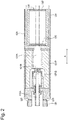
- Fig. 3 is an enlarged perspective view of a part of a power source unit.
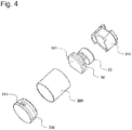
- Fig. 4 is an exploded perspective view in which the part of the power source unit is disassembled.
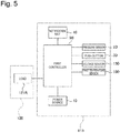
- Fig. 5 is a block diagram of the flavor generation device.
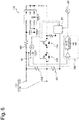
- Fig. 6 is a diagram illustrating an electric circuit of the power source unit.
- Fig. 7 is a diagram illustrating an electric circuit of the atomization unit and the power source unit in a state where a load is connected to the power source.
- a flavor generation device 100 may be a non-combustion-type flavor inhaler for sucking a flavor without combustion.
- the flavor generation device 100 may have a shape extending along a predetermined direction A that is a direction toward a suction port end E1 from a non-suction port end E2.
- the flavor generation device 100 may include one end E1 having a suction port 141 through which a user sucks a flavor and the other end E2 on a side opposite to the suction port 141.
- the flavor generation device 100 may include a power source unit 110 and an atomization unit 120.
- the atomization unit 120 may include a case 123, and a load 121R disposed inside the case 123.
- the case 123 may form a part of the outermost outer surface of the flavor generation device.
- the atomization unit 120 may be configured to be attachable to and detachable from the power source unit 110 via mechanical connection portions 111, 121.
- a load 121R in the atomization unit 120 is electrically connected to a power source 10 provided in the power source unit 110 via electric connection terminals (first connection portions) lilt and 121t. That is, the electric connection terminals 111t and 121t form a connection portion through which the load 121R and the power source 10 can be electrically connected to each other.
- the atomization unit 120 includes an aerosol source to be sucked by a user, and the electric load 121R that atomizes the aerosol source upon receipt of electric power from the power source 10.
- the load 121R may be an element that can generate aerosol from the aerosol source using electric power from the power source.
- the load 121R may be a heating element such as a heater or an element such as an ultrasonic generator.
- the heating element may include a heating resistor, a ceramic heater, and an induction-heating-type heater.
- the atomization unit 120 may include a reservoir 121P, a wick 121Q, and a load 121R.
- the reservoir 121P may be configured to reserve a liquid aerosol source.
- the reservoir 121P may be a porous body made of a material such as a resin web, for example.
- the wick 121Q may be a liquid retaining member that draws the aerosol source from the reservoir 121P using a capillary phenomenon.
- the wick 121Q can be made of, for example, glass fiber or porous ceramic.
- the load 121R heats the aerosol source retained in the wick 121Q.
- the load 121R is formed by, for example, a resistance heating element (for example, a heating wire) wound around the wick 121Q.
- Air flowing from an inlet 125 which takes in outside air into a flow path, passes near the load 121R in the atomization unit 120 through a flow path 122A.
- the aerosol generated by the load 121R flows toward the suction port 141 together with the air.
- the flow path 122A refers to a path between the inlet 125 and the suction port 141, among paths through which a fluid can flow. That is, the flow path 122A passes an air flow generated by user's suction.
- the flow path 122A reaches the suction port 141 through the atomization unit 120 from the connection portion between the atomization unit 120 and the power source unit 110.
- the inlet 125 is provided at the connection portion 121 of the atomization unit 120. Unlike the present embodiment, the inlet 125 may be provided at the connection portion 111 of the power source unit 110. Unlike the present embodiment, the inlet 125 may be also provided at the connection portion 121 of the atomization unit 120 and the connection portion 111 of the power source unit 110. In any case, the inlet 125 is provided at the connection portion between the atomization unit 120 and the power source unit 110.
- the aerosol source may be a liquid at normal temperature.
- Examples of the aerosol source to be used can include polyhydric alcohols.
- the aerosol source may contain a tobacco raw material or an extract derived from the tobacco raw material, which releases a smoking flavor component when it is heated.
- the liquid aerosol source at normal temperature is described in detail as an example in the embodiment described above, but alternatively a solid aerosol source at normal temperature can be used.
- the load 121R may be in contact with or close to the solid aerosol source to generate the aerosol from the solid aerosol source.
- the atomization unit 120 may include a flavor unit (cartridge) 130 configured to be replaceable.
- the flavor unit 130 may include a cylindrical body 131 that accommodates the flavor source.
- the cylindrical body 131 may include a membrane member 133 and a filter 132 through which air or aerosol can pass.
- the flavor source may be provided in a space formed by the membrane member 133 and the filter 132.
- the flavor source in the flavor unit 130 adds the smoking flavor component to the aerosol generated by the load 121R of the atomization unit 120.
- the flavor added to the aerosol by the flavor source is carried to the suction port 141 of the flavor generation device 100.
- the flavor source in the flavor unit 130 may be solid at normal temperature.
- the flavor source includes a raw material piece of a plant material that adds the smoking flavor component to the aerosol.
- a compact obtained by forming the tobacco material such as shredded tobacco or a tobacco raw material into a granular shape may be used.
- the flavor source may be a compact obtained by forming the tobacco material into a sheet shape.
- the raw material piece included in the flavor source may be formed by plants (for example, mint and herb) other than tobacco.
- the flavor source may be added with a flavoring agent such as menthol.
- the flavor generation device 100 may include a mouthpiece having the suction port through which a user sucks a suction component.
- the mouthpiece may be configured to be attachable to and detachable from the atomization unit 120 or the flavor unit 130, or may be configured integrally with them.
- the power source unit 110 may include a case 113, the power source 10, a pressure sensor 20, a first controller 50, and a temperature sensor 160.
- the power source 10, the pressure sensor 20, the first controller 50, and the temperature sensor 160 may be provided in the case 113.
- the case 113 may form a part of the outermost outer surface of the flavor generation device.
- the power source 10 is configured to be electrically connected to or connectable to the load 121R that atomizes the aerosol source.
- the power source 10 may be replaceable with respect to the power source unit 110.
- the power source 10 may be, for example, a rechargeable battery such as a lithium-ion secondary battery.
- the secondary battery may include a positive electrode, a negative electrode, a separator that separates the positive electrode and the negative electrode, and an electrolytic solution or an ionic liquid.
- the electrolytic solution or the ionic liquid may be, for example, a solution containing an electrolyte.
- the positive electrode is formed of, for example, a positive electrode material such as a lithium oxide
- the negative electrode is formed of, for example, a negative electrode material such as graphite.
- the electrolytic solution may be, for example, a lithium salt organic solvent.
- the pressure sensor 20 is configured to output a value of a pressure change in the flavor generation device 100 generated by user's suction or blowing through the suction port 141.
- the pressure sensor 20 may be a sensor that outputs an output value (for example, a voltage value or a current value) according to air pressure that changes depending on a flow rate (that is, a user's puff operation) of air to be sucked toward the suction port side from the non-suction port side.
- the output value of the pressure sensor 20 may have a pressure dimension, or may have a flow rate or a flow velocity of air to be sucked instead of the pressure dimension. Examples of such a pressure sensor may include a capacitor microphone sensor and a known flow rate sensor.
- the first controller 50 performs various controls of the flavor generation device 100.
- the first controller 50 may control the electric power to be supplied to the load 121R.
- the flavor generation device 100 may include a first switch 172 that can electrically connect and disconnect the load 121R and the power source 10 (see Fig. 6 ).
- the first switch 172 is opened and closed by the first controller 50.
- the first switch 172 may be formed by a MOSFET, for example.
- the first switch 172 When the first switch 172 is turned on, the electric power is supplied from the power source 10 to the load 121R. On the other hand, when the first switch 172 is turned off, the supply of the electric power from the power source 10 to the load 121R is stopped. The first switch 172 is turned on and off by the first controller 50.
- the power source unit 110 may include a request sensor capable of outputting an operation request signal that is a signal for requesting the operation of the load 121R.
- the request sensor may be, for example, a push button 30 pressed by the user or the pressure sensor 20 described above.
- the first controller 50 acquires an operation request signal for the load 121R and generates a command for operating the load 121R.
- the first controller 50 outputs a command for operating the load 121R to the first switch 172, and the first switch 172 is turned on in response to the command.
- the first controller 50 may be configured to control the electric power to be supplied from the power source 10 to the load 121R.
- the aerosol source is vaporized or atomized by the load 121R.
- the power source unit 110 may include a voltage sensor 150 that can acquire or estimate an output voltage of the power source 10.
- the first controller 50 can perform a predetermined control according to the output value of the voltage sensor 150.
- the first controller 50 can detect or estimate a remaining amount of the power source 10 or abnormality of the power source 10 based on the output value of the voltage sensor 150.
- the first controller 50 may notify the user of the detected information by controlling a notification unit 40.
- the voltage sensor 150 may be configured to convert an analog voltage value of the power source 10 into a digital voltage value using a predetermined correlation and to output the digital voltage value.
- the voltage sensor 150 may include an A/D converter that converts an analog input value into a digital output value.
- the power source unit 110 may include a first resistor 152 and a second resistor 153 that are electrically connected in series with each other.
- the first resistor 152 is electrically connected to the power source 10 and is provided to connect a pair of electric terminals 111t to each other.
- One end of the second resistor 153 is connected to the first resistor 152, and the other end of the second resistor 153 is connected to the voltage sensor 150.
- Electric resistance values of the first resistor 152 and the second resistor 153 are known.
- the electric resistance values of the first resistor 150 and the second resistor 152 may be preferably constant regardless of the state of the power source 10.
- the notification unit 40 issues a notification for notifying the user of various types of information.
- the notification unit 40 may be, for example, a light emitting element such as an LED.
- the notification unit 40 may be an acoustic element that generates sound or a vibrator that generates vibration.
- the notification unit 40 may be configured by any combination of the light emitting element, the acoustic element, and the vibrator.
- the notification unit 40 may be provided at any location of the flavor generation device 100.
- the notification unit 40 may be built in the first controller 50, or may be disposed at a location different from the first controller 50.
- the notification unit 40 may be provided anywhere where the user can recognize the notification by the notification unit 40.
- the power source unit 110 may include a sensor capable of outputting a detected value or estimated value of the state of the power source 10.
- the detected value or estimated value of the sensor is sent to the first controller 50.
- the sensor capable of outputting the detected value or estimated value of the state of the power source 10 may be a first temperature sensor 160 that outputs the detected value or estimated value of a temperature of the power source 10.
- the first temperature sensor 160 may be provided anywhere where the first temperature sensor 160 can output the detected value or estimated value of the temperature of the power source 10. In the illustrated embodiment, the first temperature sensor 160 is built in the first controller 50.
- the sensor capable of outputting the detected value or estimated value of the state of the power source 10 may be a sensor that measures or estimates an internal resistance (a DC component of the impedance) of the power source 10 instead of the first temperature sensor 160.
- the voltage sensor 150 may be used, for example.
- the power source unit 110 includes a first member 300 and a second member 310 that cover the pressure sensor 20, the temperature sensor 160, and the first controller 50.
- the first member 300 and the second member 310 are formed in a cylindrical shape, for example.
- the second member 310 is fitted to one end of the first member 300.
- Aa cap 330 is provided at the other end of the first member 300.
- the cap 330 may be formed with an opening 114 that is opened to the atmosphere.
- the inside of the first member 300 and the second member 310 is opened to the atmosphere.
- the power source unit 110 may be configured to be connectable to a charging unit 200 that can charge the power source 10 (see Fig. 8 ).
- a combination of the power source unit 110 and the charging unit 200 forms a flavor generation system of the present invention.
- Fig. 8 is a diagram illustrating an electric circuit of the flavor generation system including the power source unit and the charging unit.
- Fig. 9 is a block diagram of the charging unit.
- the charging unit 200 When the charging unit 200 is connected to the power source unit 110, the charging unit 200 is electrically connected to the power source 10 of the power source unit 110.
- the charging unit 200 may include a current sensor 230, a voltage sensor 240, a second controller 250, and a second temperature sensor 260.
- the charging unit 200 is electrically connected to the power source unit 110 by a pair of connection terminals 211t.
- a pair of electric terminals of the power source unit 110 used to electrically connect the charging unit 200 may be the same as the pair of electric terminals 111t of the power source unit 110 used to electrically connect the load 121R.
- the pair of electric terminals of the power source unit 110 used to electrically connect the charging unit 200 may be provided separately from the pair of electric terminals 111t.
- the second controller 250 of the charging unit 200 may be configured to be incapable of communicating with the first controller 50 of the power source unit 110. That is, a communication terminal for communicating between the second controller 250 of the charging unit 200 and the first controller 50 of the power source unit 110, and a communication system including a receiver and a transmitter are unnecessary.
- the power source unit 110 in a connection interface with the charging unit 200, has only two electric terminals, one for a main positive bus and the other for a main negative bus. In this case, the power source unit 110 and the charging unit 200 are electrically connected to each other only by the main positive bus and the main negative bus.
- the charging unit 200 may include an inverter (AC/DC converter) that converts AC into DC.
- the current sensor 230 is a sensor that acquires a value of a charging current supplied from the charging unit 200 to the power source 10.
- the voltage sensor 240 is a sensor that acquires a voltage between the pair of electric terminals of the charging unit 200. In other words, the voltage sensor 240 acquires a potential difference applied between the pair of connection terminals 111t of the power source unit.
- the second controller 250 is configured to control a charge of the power source 10.
- the second controller 250 may control the charge of the power source 10 using output values from the temperature sensor 260, the current sensor 230 and/or the voltage sensor 240.
- the charging unit 200 may further include a voltage sensor that acquires DC voltage output from the inverter and a converter that can increase and/or decrease a DC voltage output from the inverter or the external power source 210.
- the power source unit 110 may include a second switch 174 between the power source 10 and the electric connection terminals (first connection portions) 111t and 121t.
- the second switch 174 is opened and closed by the first controller 50.
- the second switch 174 may be formed by a MOSFET, for example.
- the second switch 174 is turned on and off by the first controller 50.
- the charging current can flow to the power source 10 from the charging unit 200.
- the second switch 174 is turned off, the charging current can hardly flow to the power source 10 from the charging unit 200. That is, even when the charging unit 200 is connected to the power source 110, the first controller 50 can temporarily or permanently stop the charge of the power source 10 with the second switch 174.
- the charging unit 200 may include a conversion unit 290 that can convert a voltage or a current of the input electric power and output the converted voltage or current.
- the second controller 250 is configured to be capable of adjusting the value of the voltage or current to be output from the conversion unit 290 by operating the conversion unit 290. Thus, the second controller 250 can adjust the charging current for charging the power source 10.
- the first controller 50 of the power source unit 110 may be configured to be capable of determining whether the charging unit 200 is connected.
- the first controller 50 can determine, based on the change in a voltage drop amount in the second resistor 153 described above, whether the charging unit 200 is connected.
- the voltage drop amount in the second resistor 153 differs depending on a case where nothing is connected to the pair of electric terminals 111t and a case where the external unit such as the charging unit 200 or the atomization unit 120 is connected to the pair of electric terminals 111t. Accordingly, the first controller 50 can detect the connection of the external unit such as the charging unit 200 or the atomization unit 120 by acquiring the voltage drop amount in the second resistor 153.
- the first controller 50 can estimate that the charging unit 200 is not connected to the connection terminals 111t. In addition, when detecting a low-level voltage value V wake , the first controller 50 can estimate that the charging unit 200 is connected to the connection terminals 111t.
- a current flows from the power source 10 to the first controller 50 via the first resistor 152 and the second resistor 153. Accordingly, since the voltage drop occurs in the second resistor 153 due to the current flowing through the second resistor 153, the first controller 50 detects a high-level voltage value V wake at the second resistor 153.
- the first controller 50 may detect the connection of the charging unit 200, for example, based on a change in potential difference between the pair of connection terminals 111t.
- both of the first controller 50 of the power source unit 110 and the second controller 250 of the charging unit 200 are configured to be capable of controlling the charge of the power source 10, in particular, the charging speed of the power source 10. That is, the first controller 50 can control the charging speed by operating the second switch 174.
- the charging speed can be expressed using a charge rate (a so-called C-rate) or a value of electric power per unit time for charging the power source 10.
- the control of the charging speed includes setting the charging speed to "0.” That is, the control of the charging speed includes stopping the charge.
- the first controller 50 can control the charging speed by repeating opening and closing of the second switch 174 at the desired time interval.
- the first controller 50 can stop the charge by maintaining the second switch 174 in an open state. In any case, it will be apparent that the charging speed is slower than that in a case where the second switch 174 is maintained in a closed state.
- the first controller 50 preferably controls the charging speed based on the output value of the sensor capable of outputting the detected value or estimated value of the state of the power source 10.
- a sensor may be, for example, the first temperature sensor 160 described above.
- the first controller 50 can control, based on the temperature of the power source 10, whether to set the charging speed to "0," by operating the second switch 174.
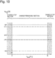
- Fig. 10 is a map illustrating an example of a correlation between a temperature and a charging speed of the power source.
- the first controller 50 may close the second switch 174.
- the second switch 174 When the second switch 174 is closed, the charge of the power source 10 is permitted, whereby the charging speed becomes larger than "0.”
- the first controller 50 may open the second switch 174. When the second switch 174 is opened, the charge of the power source 10 is stopped, whereby the charging speed becomes "0.”
- the first controller 50 may be configured to open the second switch 174 in a case where the output value of the first temperature sensor 160 is equal to or lower than a first predetermined temperature, which causes solidification of the electrolytic solution or the ionic liquid, or in a case where the temperature of the power source 10 is estimated to be equal to or lower than the first predetermined temperature based on the output value of the first temperature sensor 160. In this way, the power source 10 can be protected even in the temperature range which causes solidification of the electrolytic solution or the ionic liquid of the power source 10.
- the first predetermined temperature may be, for example, 0°C as illustrated in Fig. 10 .
- the temperature of the power source 10 becomes equal to or lower than 0°C, moisture in the power source 10, e.g., moisture in the electrolytic solution may be solidified. Under such circumstances, charging the power source 10 easily causes acceleration of the deterioration of the power source 10. Accordingly, in such a temperature range, the charge of the power source 10 is preferably stopped.
- the first controller 50 may be configured to open the second switch 174 in a case where the output value of the first temperature sensor 160 is equal to or lower than a second predetermined temperature at which electrodeposition occurs on the electrode in the power source 10, or in a case where the temperature of the power source 10 is estimated to be equal to or lower than the second predetermined temperature based on the output value of the first temperature sensor 160.
- the power source 10 is a lithium-ion secondary battery
- metallic lithium may be deposited (electrodeposited) on a surface of the negative electrode. Therefore, the charge is preferably stopped.
- the second predetermined temperature may depend on the type of the lithium-ion secondary battery, it is necessary to specify the second predetermined temperature by an experiment in advance.
- the second predetermined temperature may be the same as or different from the first predetermined temperature.
- the first controller 50 may be configured to open the second switch 174 in a case where the output value of the first temperature sensor 160 is equal to or higher than a third predetermined temperature at which a change in structure or composition of the electrode occurs in the power source 10, or in a case where the temperature of the power source 10 is estimated to be equal to or higher than the third predetermined temperature based on the output value of the first temperature sensor 160.
- the first controller 50 preferably stops the charge.
- An example of the change in structure or composition of the electrode is aggregation of an active material, conductive additive, and binder or detachment of an active material, conductive additive, and binder from the electrode.
- the third predetermined temperature may be, for example, 60°C.
- the information about the correlation (first correlation) between the temperature and the charging speed of the power source as illustrated in Fig. 10 may be stored in a memory in the first controller 50.
- the first controller 50 may control the charging speed based on the output value of the sensor that measures or estimates the internal resistance of the power source 10. That is, the sensor capable of outputting the detected value or estimated value of the state of the power source 10 may be a sensor that measures or estimates the internal resistance of the power source 10, e.g., the voltage sensor 150.
- the power source 10 can be protected by controlling the charging speed based on the internal resistance of the power source 10 as described above, for example, by reducing the charging speed when the internal resistance of the power source 10 increases.
- the second controller 250 can control the charging speed by operating the conversion unit 290. It will be apparent to those skilled in the art that the charging speed can be controlled in a case where the conversion unit 290 performs a current control mode that controls CV charging (described later) and an output current, as an example. That is, the second controller 250 can adjust the value of the voltage or current to be output from the conversion unit 290.
- the control of the charging speed includes setting the charging speed to "0.” That is, the control of the charging speed also includes stopping the charge.
- the conversion unit 290 may be configured to be capable of performing a first charging mode and a second charging mode which are different in the charging speed.
- the second charging mode may be a mode in which a value of the electric power or current per unit time that can be output by the conversion unit 290 is greater than that in the first charging mode.
- the second charging mode is also referred to as a "quick charging mode.”
- the first charging mode is also referred to as a "normal charging mode.”
- the second controller 250 may be configured to be capable of performing a third mode in which a value of the electric power or current per unit time that can be output by the conversion unit 290 is smaller than that in the first charging mode.
- the third mode is performed in a state where a remaining amount of the power source 10 is decreased significantly, i.e., in an over-discharge state or a deep discharged state.
- the over-discharge state or the deep discharged state may be a state in which the voltage value of the power source 10 is lower than a discharge termination voltage. In the over-discharge state or the deep discharged state, the power source 10 is easily damaged. Therefore, the second controller 250 needs to charge the power source 10 at a low speed and attempt to recover the power source 10 (return to the state where the voltage value is equal to or higher than the discharge termination voltage).
- the second controller 250 preferably controls the charging speed based on the output value of the second temperature sensor 260. That is, the second controller 250 controls the charging speed as described above, i.e., selects the mode based on the temperature of the charging unit 200.
- Fig. 11 is a map illustrating an example of a correlation between a temperature and a charging speed of the charging unit 200.
- the second controller 250 causes the conversion unit 290 to perform the second charging mode in a case where the output value of the second temperature sensor 260 is equal to or higher than a first threshold.
- the second controller 250 causes the conversion unit 290 to perform the first charging mode in a case where the output value of the second temperature sensor 260 is lower than the above-described first threshold.
- the charging speed is expressed using a C-rate.
- the charging speed at which the power source 10 is charged to a fully charged state from the discharge termination state for one hour can be represented by 1.0C as a reference.
- the charge is performed faster than 1.0C.
- the charge rate lower than 1.0C the charge is performed slower than 1.0C.
- the charging speed of 0.5C is used in the first charging mode
- the charging speed of 2.0C is used in the second charging mode
- the charging speed of 0.05C is used in the third charging mode.
- the first threshold may be, for example, 10°C. Therefore, the second controller 250 does not perform the quick charging mode at low temperature to reduce the load applied to the power source 10, which can prevent a phenomenon such as electrodeposition.
- the second controller 250 may select one of the first charging mode and the second charging mode based on the other conditions, in a case where the output value of the second temperature sensor 260 is equal to or higher than the above-described first threshold.
- the second controller 250 is configured to be capable of adjusting a value of the voltage or current to be output from the conversion unit 290 by operating the conversion unit 290, based on a value related to the remaining amount of the power source 10 and the output value of the second temperature sensor 260.
- the value related to the remaining amount of the power source 10 is not limited to a particular value, but may be, for example, the voltage of the power source 10.
- the voltage of the power source 10 can be acquired by the voltage sensor 240.
- the second controller 250 may be configured to perform only constant current charging (CC charging) of the constant current charging and constant voltage charging (CV charging) in a case where the output value of the temperature sensor 260 is smaller than the first threshold.
- the charging speed of the constant current charging may be any value between 0.5 to 1.0C, and, as an example, may be 1.0C.
- the second controller 250 may perform the constant current charging and the constant voltage charging in a case where the output value of the temperature sensor 260 is equal to or higher than the first threshold.
- the second controller 250 may perform the constant voltage charging.
- the second controller 250 may perform the constant current charging.
- the switching voltage may be, for example, 4.2 V.
- the second controller 250 may control the charging speed based on a correlation illustrated in Fig. 12 .
- both of the constant current charging (CC charging) and the constant voltage charging (CV charging) are performed even when the output value of the temperature sensor 260 is lower than the first threshold.
- the switching voltage in a case where the output value of the temperature sensor 260 is lower than the first threshold is smaller than the switching voltage in a case where the output value of the temperature sensor 260 is equal to or higher than the first threshold.
- the second controller 250 may be configured so that the switching value which is a value related to the remaining amount of the power source when the constant current charging is switched to the constant voltage charging in a case where the output value of the temperature sensor 260 is lower than the first threshold, e.g., a switching value (switching voltage) of the voltage value of the power source 10 is smaller than the switching value in a case where the output value of the temperature sensor 260 is equal to or higher than the first threshold.
- the constant voltage charging can be performed before charge completion, even at low temperature at which the full charge capacity of the power source 10 is decreased.
- the power source 10 can be charged to near full charge while avoiding overcharge.
- the information about the correlation (second correlation) between the temperature and the charging speed of the charging unit 200 as illustrated in Fig. 11 or 12 may be stored in a memory in the second controller 250.
- an object to be operated by the first controller 50 is different from an object to be operated by the second controller 250.
- the first controller 50 and the second controller 250 share the control of the charging speed by operating the respective objects different from each other.
- the charging speed is controlled by both of the first controller 50 and the second controller 250. More specifically, the second controller 250 may adjust (operate) a value of the voltage or current to be output from the conversion unit 290 by operating the conversion unit 290 and the first controller 50 may control (operate) whether to set the charging speed to 0" by operating the second switch 174.
- the number of first options for the determination to be made by the first controller 50 is preferably smaller than the number of second options for the determination to be made by the second controller 250.
- the first controller 50 has two options (first options): to turn on or to turn off the second switch 174 based on the output value of the first temperature sensor 160.
- the second controller 250 has more than two options: to perform the first charging mode, the second charging mode, the third charging mode, the CV charging, or the CC charging based on the output value of the second temperature sensor 260.
- the first controller 50 need not to provide high performance by allowing the external unit other than the power source unit 110, i.e., the charging unit 200 to have many options, whereby a configuration of the power source unit 110 and consequently the flavor generation device 100 can be simplified.
- the above-described effect is particularly preferable.
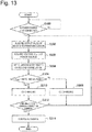
- Fig. 13 is a flowchart illustrating an example of a control flow by the second controller 250 of the charging unit 200. Firstly, the second controller 250 determines whether the charging unit 200 is connected to the power source unit 110 (step S300). The second controller 250 waits until the charging unit 200 is connected to the power source unit 110.
- the connection between the charging unit 200 and the power source unit 110 can be detected by a known method. For example, when a change in voltage between the pair of electric terminals 211t of the charging unit 200 is detected by the voltage sensor 240, the second controller 250 can determine whether the charging unit 200 is connected to the power source unit 110. Instead of the voltage sensor 240, a mechanical switch may be used in which the output is switched between the connected state and the disconnected state between the charging unit 200 and the power source unit 110.
- the second controller 250 acquires an output value of the second temperature sensor 260 and a voltage (V BATT ) of the power source 10 (steps S302 and S303). Either of the output value of the second temperature sensor 260 or the voltage (V BATT ) of the power source 10 may be acquired first, or they may be acquired at the same time.
- the second controller 250 can acquire the voltage (V BATT ) of the power source 10 from the voltage sensor 240. Note that when the voltage of the power source 10 is acquired by the voltage sensor 240, the first controller 50 of the power source unit 110 maintains the second switch 174 in the closed state ("on" state).
- the second controller 250 sets the charging mode based on the output value of the second temperature sensor 160 (step S304). Specifically, the second controller 250 sets the charging speed (charging mode) of the power source 10 based on the correlation (second correlation) for setting the charging conditions of the power source 10 as illustrated in Fig. 11 or 12 . Preferably, the second controller 250 sets the charging speed (charging mode) based on both of the output value of the second temperature sensor 160 and the value related to the remaining amount of the power source 10, e.g., the voltage (V BATT ) of the power source 10.
- V BATT the voltage
- the second controller 250 determines, as necessary, which one of the constant voltage charging and the constant current charging is to be performed (step S306). Specifically, when the voltage (V BATT ) of the power source 10 is lower than the above-described switching voltage, the second controller 250 supplies the current to the power source unit 110 by the constant current charging (step S308).
- the second controller 250 acquires an output value of the second temperature sensor 260 and a voltage (V BATT ) of the power source 10 again (steps S302 and S303). Then, the second controller 250 sets the charging speed (charging mode) again based on both of the output value of the second temperature sensor 160 and the voltage (V BATT ) of the power source 10. Note that the charging speed can be set by adjusting a value of the voltage or current to be output from the conversion unit 290 by operating the conversion unit 290. Thereafter, as described above, the second controller 250 determines, as necessary, which one of the constant voltage charging and the constant current charging is to be performed (step S306).
- the second controller 250 supplies the current to the power source unit 110 by the constant voltage charging (step S310).
- the constant voltage charging as the charge of the power source 10 proceeds, a difference between the charging voltage and the voltage of the power source 10 is reduced, whereby the charging current decreases.
- the second controller 250 acquires an output value of the second temperature sensor 260 and a voltage (V BATT ) of the power source 10 again (steps S302 and S303). Then, the second controller 250 sets the charging speed (charging mode) again based on both of the output value of the second temperature sensor 160 and the voltage (V BATT ) of the power source 10.
- the second controller 250 determines that the charge has been completed, and stops the charge of the power source 10 (step S314).
- the second controller 250 preferably acquires not only the output value of the temperature sensor 260 but also the voltage (V BATT ) of the power source 10, and sets the charging mode also based on the voltage of the power source 10.
- the second controller 250 can use the value related to the remaining amount of the power source instead of the voltage of the power source 10. That is, in step S304, the second controller 250 may adjust a value of the voltage or current to be output from the conversion unit 290 by operating the conversion unit 290, based on the value related to the remaining amount of the power source 10 and the output value of the second temperature sensor 260.
- the second controller 250 periodically acquires the output value of the second temperature sensor 260, and selects the charging mode based on the acquired output value.
- the second controller 250 may select the charging mode using the output value of the second temperature sensor 260 acquired once after the power source unit 110 is connected. That is, the second controller 250 may acquire the output value of the second temperature sensor 260 only once in the determination of the charging speed.
- the second controller 250 determines the charging mode based on the correlation illustrated in Fig. 11 or 12 according to a change in voltage of the power source 10, assuming that the temperature of the charging unit 200 is not changed.
- step S308 the process returns to step S306 rather than to step S302.
- the process returns to S312 rather than to step S302. Accordingly, the control flow can be simplified.
- the second controller 250 sets the charging mode in step S304 before determining, in step S306, which one of the constant voltage charging and the constant current charging is to be performed. Since the second correlation used in step S304 specifies the charging speed in the constant current charging, the charging mode may be instead determined in step S304 after it is determined, in step S306, that the constant current charging is to be performed.
- Fig. 14 is a flowchart illustrating an example of a control flow by the first controller of the power source unit.
- the first controller 50 determines whether the charging unit 200 is connected to the power source unit 110 (step S402).
- the connection of the charging unit 200 to the power source unit 110 can be detected by the above-described method.
- the first controller 50 turns on the second switch 174 (step S403a) to electrically connect the power source unit 110 and the charging unit 200, so that the second controller 250 can acquire the voltage (V BATT ) of the power source 10 in step S303 described above. Then, the first controller 50 turns off the second switch 174 to electrically disconnect the power source unit 110 from the charging unit 200 (step S403b).
- the first controller 50 When the first controller 50 detects the connection of the charging unit 200 to the power source unit 110, the first controller 50 acquires an output value of the first temperature sensor 160 provided in the power source unit (step S404).
- the first controller 50 sets the charging speed based on the first correlation for setting the charging conditions of the power source based on the output value of the first temperature sensor 160 (steps S406, S407, and S408).
- the first correlation is as described with reference to Fig. 10 .
- the first controller 50 preferably controls the charging speed to be set to "0" or not by operating the second switch 174. More specifically, the first controller 50 controls the charging speed to be set to "0" or not by operating the second switch 174, based on the output value of the first temperature sensor 160.
- the first controller 50 opens the second switch 174 (steps S406 and S408) in a case where the temperature of the power source 10 is equal to or lower than the first predetermined temperature or in a case where the temperature of the power source 10 is estimated to be equal to or lower than the first predetermined temperature based on the output value of the first temperature sensor 160.
- the first predetermined temperature may be, for example, 0°C.
- the first controller 50 opens the second switch 174 (steps S406 and S408) in a case where the temperature of the power source 10 is equal to or higher than the third predetermined temperature, or in a case where the temperature of the power source 10 is equal to or higher than the third predetermined temperature based on the output value of the first temperature sensor 160.
- the first controller 50 closes the second switch 174 (step S407) in a case where the output value of the first temperature sensor 160 is within a predetermined temperature range, e.g. within a range of 0 to 60°C. In this manner, the first controller 50 can permit the charge only in a case where the temperature of the power source 10 is in a temperature conditions suitable for the charge.
- the first controller 50 detects whether the charging unit 200 is disconnected. In a state where the charging unit 200 is connected, the first controller 50 maintains the second switch 174 in the closed state except for the case where the voltage of the power source 10 is acquired by the voltage sensor 150. This can maintain a state of being capable of charging the power source 10.
- the first controller 50 of the power source unit 110 and the second controller 250 of the charging unit 200 share the control of the charging speed of the power source 10.
- the first controller 50 and the second controller 250 are configured to control the charging speed based on the output values of the first temperature sensor 160 and the second temperature sensor 260, respectively, i.e., based on values related to the same physical quantity.
- the first controller 50 and the second controller 250 are configured to control the charge of the power source 10 based on the first correlation and the second correlation as illustrated in Figs. 10 to 12 .
- the first controller 50 and the second controller 250 are preferably configured to control the charge of the power source 10 by preferentially using the first correlation out of the first correlation and the second correlation. That is, the first correlation is preferably a correlation for determining whether to set the charging speed to "0", as illustrated in Fig. 10 .
- the second controller 250 adjusts the charging speed to a value larger than "0,” and the first controller 50 determines whether to set the charging rate to "0.”
- the first temperature sensor 160 Since the first temperature sensor 160 is disposed to be closer to the power source 10 than the second temperature sensor 260, the first temperature sensor 160 can acquire more accurately the temperature of the power source 10. On the other hand, increases in weight and size of the power source unit 110 are not preferable in view of article characteristics of the flavor generation device 100 that is carried routinely by the user and that is held by a mouth of the user in use. Then, the second controller 250 makes a primary determination of the charging speed with many options based on the output value of the second temperature sensor 260. The first controller 50 makes a secondary (final) determination of the charging speed with few options based on the output value of the first temperature sensor.
- the objects to be operated for the charge of the power source 10 are properly divided into the power source unit 110 and the charging unit 200, whereby more sophisticated control of the charging speed is made possible according to the state (environment) of the power source, for example.
- the first controller 50 and the second controller 250 may control the charge of the power source 10 without communicating with each other. Therefore, a configuration of the power source unit 110 can be simplified. Even in such a case, the first controller 50 and the second controller 250 share the control of the charging speed of the power source, whereby sophisticated control of the charging speed is made possible.
- the sophisticated control of the charging speed is advantageous in the following other points. Firstly, since the power source 10 can be protected, the lifetime of the power source 10 is increased. Secondly, since the electric power supplied from the charging unit 200 is used for the charge of the power source 10 without being wasted as compared with a case where the temperature of the power source 10 is low or high or a case where the internal resistance of the power source 10 is high, the charging efficiency is improved. That is, a flavor generation system with sophisticated control of the charging speed, a method of controlling the flavor generation system, and a program have an energy-saving effect.
- Fig. 15 is a flowchart illustrating another example of a control flow by the second controller 250 of the charging unit 200.
- the same reference numerals are denoted for steps similar to steps illustrated in Fig. 13 , and the description thereof will be omitted.
- the second controller 250 determines whether the charging unit 200 is connected to the power source unit 110 (step S300). The second controller 250 waits until the charging unit 200 is connected to the power source unit 110.
- the second controller 250 applies a test current toward the power source unit 110, and estimates or measures an internal resistance of the power source 10 (step S301). It will be apparent to those skilled in the art that the internal resistance of the power source 10 can be obtained by dividing a value of the voltage applied to the power source unit 110 when the test current is applied by the value of the test current. In this way, the state of the power source 10 can be estimated.
- the second controller 250 acquires a voltage (V BATT ) of the power source 10 (step S303). Note that, in a period from step S301 to step S303, the first controller 50 of the power source unit 110 performs step S403a and step S403b described above to maintain the second switch 174 in the closed state ("on" state).
- the second controller 250 sets the charging mode based on the internal resistance of the power source 10 (step S304).
- the second controller 250 determines, as necessary, which one of the constant voltage charging and the constant current charging is to be performed (step S306). Specifically, when the voltage (V BATT ) of the power source 10 is lower than the above-described switching voltage, the second controller 250 supplies the current to the power source unit 110 by the constant current charging (step S308). Similarly, when the voltage (V BATT ) of the power source 10 is equal to or higher than the above-described switching voltage, the second controller 250 supplies the current to the power source unit 110 by the constant voltage charging (step S310). Note that the subsequent steps are the same as those in Fig. 13 , and the description thereof will be omitted.
- the control flow by the first controller 50 may be substantially similar to the steps illustrated in Fig. 14 .
- the first controller 50 operates the second switch 174 to maintain it in an "on" state. Accordingly, a period from step S403a to S403b illustrated in Fig. 14 needs to be increased.
- the second controller 250 may set the charging speed based on an output value of a sensor that acquires a value having a physical quantity other than the temperature, instead of the output value of the second temperature sensor 260. Even in such a case, the first controller 50 may set the charging speed based on the output value of the first temperature sensor 160. In this way, the first controller 50 and the second controller 250 can set the charging speed based on the output values of sensors that output values related to physical quantities different from each other, respectively.
- the first controller 50 Since the first controller 50 is disposed to be close to the power source 10, the first controller 50 can acquire more accurately the temperature of the power source 10. On the other hand, increases in weight and size of the power source unit 110 are not preferable in view of article characteristics of the flavor generation device 100 that is carried routinely by the user and that is held by a mouth of the user in use. Then, the second controller 250 makes a primary determination of the charging speed with many options based on the internal resistance of the power source 10 that can be acquired accurately even away from the power source 10. The first controller 50 makes a secondary (final) determination of the charging speed with few options based on the temperature of the power source 10.
- the objects to be operated for the charge of the power source 10 are properly divided into the power source unit 110 and the charging unit 200, whereby more sophisticated control of the charging speed is made possible according to the state (environment) of the power source, for example.
- the sophisticated control of the charging speed is advantageous in the following other points. Firstly, since the power source 10 can be protected, the lifetime of the power source 10 is increased. Secondly, since the electric power supplied from the charging unit 200 is used for the charge of the power source 10 without being wasted as compared with a case where the temperature of the power source 10 is low or high or a case where the internal resistance of the power source 10 is high, the charging efficiency is improved. That is, a flavor generation system with sophisticated control of the charging speed, a method of controlling the flavor generation system, and a program have an energy-saving effect.
- the discharge of electric power from the power source 10 is performed in a case where an external unit other than the charging unit 200, e.g., the atomization unit 120 is connected to the connection terminals 111t of the power source unit 110.
- the external unit such as the atomization unit 120 preferably includes a controller that can control the discharge of electric power from the power source 10 to the external unit, and specifically, that can control the discharging speed.
- An object to be operated by the controller provided in the external unit such as the atomization unit 120 may be different from the object to be operated by the first controller 50 of the power source unit 110.
- the first controller 50 controls the discharging speed of the power source by operating a first object provided in the power source unit 110 including the power source 10, and another controller provided in the external unit further controls the discharging speed by operating a second object.
- the discharging speed can be controlled by the above-described controllers based on similar concepts to the correlations ( Figs. 10 to 12 ) used for the charge control.
- the number of first options for the determination to be made by the first controller 50 is preferably smaller than the number of second options for the determination to be made by the controller in the external unit.
- the first controller 50 determines whether to set the discharging speed to "0" based on the output value of the first temperature sensor 160. In this case, the number of options for the determination to be made by the first controller 50 is "2.”
- the controller in the external unit may perform feedback control of the temperature of the load 121R. Specifically, the controller in the atomization unit acquires the temperature of the load 121R and performs the feedback control so that the temperature of the load 121R is within a desired temperature range.
- the feedback control can be performed by pulse width modulating (PWM) or pulse frequency modulating (PFM) a current pulse or voltage pulse of the discharging current from the power source 10 to the atomization unit 130, for example.
- PWM pulse width modulating
- PFM pulse frequency modulating
- the desired temperature range of the feedback control need not always be fixed, and may change according to the progress of heating of the aerosol source by the load 121R.
- the atomization unit 120 includes a plurality of load 121R, and the loads 121R to which the feedback control is applied may be changed according to the progress of heating of the aerosol source, or the number of the load 121R to which the feedback control is applied may be increased or decreased.
- feed forward control may be used.
- the feedback control such as pulse width modulation (PWM) control or pulse frequency modulation (PFM) control can be performed by so-called PID control, for example.
- PID control a number of determinations are required to calculate proportional control, an integral gain (I gain), and a derivative gain (D gain). Accordingly, the number of first options for the determination to be made by the first controller 50 is smaller than the number of second options for the determination to be made by the controller in the atomization unit.
- a flavor generation system with sophisticated control of the discharging speed, a method of controlling the flavor generation system, and a program have an energy-saving effect.
- the number of first options for the determination to be made by the first controller 50 is smaller than the number of second options for the determination to be made by the controller in the external unit.
- the number of first options for the determination to be made by the first controller 50 may be greater than the number of second options for the determination to be made by the controller in the external unit.
- the external unit is the atomization unit
- the first controller 50 or the second controller 250 can perform any method described above. That is, the first controller 50 or the second controller 250 may include a program that causes the flavor generation system to execute the above-described method, and a storage medium in which such a program is stored.
- the flavor generation device 100 includes both of the aerosol source for generating the aerosol and the flavor source including the tobacco raw material and/or the extracts derived from the tobacco raw material for generating the smoking flavor component.
- the flavor generation device 100 may include only one of the aerosol source and the flavor source.
- flavor may be defined as a broad concept including a smoking flavor component generated from a flavor source or an aerosol source, or a smoking flavor component derived from the flavor source or the aerosol source.
- the electric load 121R is configured to act on the aerosol source to vaporize or atomize the aerosol source.
- the electric load 121R may be configured to heat the flavor source or the flavor unit to release the flavor.
- the power source 10 is configured to be electrically connected to or connectable to the load 121R that heats the flavor source.
- the electric load 121R may be configured to heat both of the aerosol source and the flavor source.
- the first controller 50 determines whether to set the charging speed to "0" (also, see the correlation in Fig. 10 ). Alternatively, the first controller 50 may determine whether the charging speed is increased or decreased. For example, the first controller 50 may set the charging speed in a case where the temperature of the power source 10 is outside the predetermined temperature range slower than that in a case where the temperature of the power source 10 within the predetermined temperature range. That is, the first controller 50 may be configured to control the amount of current or electric power to be reduced or not, the current or electric power to be input to the power source 10 from the external unit such as the charging unit 200.
- the load applied to the power source 10 can be reduced in a case where the environment around the power source 10 is poor.
- the reduction in the amount of current by the first controller 50 can be achieved by controlling the switch so that the current flows through a line having a higher electric resistance.
- the reduction in the amount of electric power by the first controller 50 can be achieved by temporarily opening the second switch 174 during the charge or temporarily opening the first switch 172 during the discharge.
Landscapes
- Engineering & Computer Science (AREA)
- Power Engineering (AREA)
- Manufacturing & Machinery (AREA)
- Chemical & Material Sciences (AREA)
- Chemical Kinetics & Catalysis (AREA)
- Electrochemistry (AREA)
- General Chemical & Material Sciences (AREA)
- Microelectronics & Electronic Packaging (AREA)
- Charge And Discharge Circuits For Batteries Or The Like (AREA)
- Secondary Cells (AREA)
Abstract
Description
- The present invention relates to a flavor generation system, a method of controlling the flavor generation system, and a program.
- In place of cigarettes, aerosol generation devices are known which generate aerosol for tasting by atomizing an aerosol source with an electric load such as a heater (PTL 1). The aerosol generation device includes a heating element that atomizes an aerosol source, a power source that supplies electric power to the heating element, and a controller that controls the load and the power source.
-
PTL 1 also discloses a method of charging a power source provided in the aerosol generation device or discharging the electric power from the power source. The method disclosed inPTL 1 includes a step of determining a rate of a charging current or a discharging current in dependence on an ambient temperature, and a step of charging the power source or discharging the electric power from the power source at the determined rate. - PTL 2 discloses a charging system for charging a secondary battery. The charging system disclosed in PTL 2 includes a temperature detection unit that detects a temperature of the secondary battery. When the temperature of the secondary battery detected by the temperature detection unit is within a range of preferred temperature preset as a temperature suitable for charge of the secondary battery, the charging current to be supplied from a charging unit to the second battery is adjusted so that the temperature of the secondary battery does not exceed an upper temperature of the preferred temperature range.
- PTL 3 discloses a charger for charging a battery in a battery pack. In a charging method disclosed in PTL 3, it is determined whether a charging current is output, based on a detected value of a temperature of the battery and a detected value of a temperature of the charger.
-
- PTL 1: National Publication of International Patent Application No.
2017-518733 - PTL 2:
Japanese Patent Laid-Open No. 2009-183105 - PTL 3:
Japanese Patent Laid-Open No. 2017-005830 - A first feature is a favor generation system including: a power source unit that includes a power source that is electrically connected to or connectable to a load for atomizing an aerosol source or heating a flavor source, and a first controller; and a charging unit that includes a second controller and that is capable of charging the power source. The first controller and the second controller are configured to be capable of controlling a charging speed of the power source. In the control of the charging speed, a first object to be operated by the first controller is different from a second object to be operated by the second controller.
- A second feature is the flavor generation system according to the first feature, including a sensor capable of outputting a detected value or an estimated value of a state of the power source. The first controller is configured to control the charging speed based on an output value of the sensor.
- The sensor capable of outputting the detected value or the estimated value of the state of the power source may be, for example, a temperature sensor that measures or estimates a temperature of the power source or a sensor that measures or estimates an internal resistance of the power source.
- A third feature is the flavor generation system according to the first or second feature, wherein the charging speed includes "0."
- A fourth feature is the flavor generation system according to any one of the first to third features, wherein the power source unit includes a first connection portion capable of being electrically connected to the charging unit, and a switch between the power source and the first connection portion, and the first controller is configured to control the charging speed to be set to "0" or not by operating the switch.
- A fifth feature is the flavor generation system according to the fourth feature, wherein the power source unit includes a first temperature sensor that outputs a detected value or an estimated value of a temperature of the power source, and the first controller is configured to control the charging speed to be set to "0" or not by operating the switch, based on an output value of the first temperature sensor.
- A sixth feature is the flavor generation system according to the fifth feature, wherein the power source includes an electrolytic solution or an ionic liquid. The first controller is configured to open the switch in a case where the output value of the first temperature sensor is equal to or lower than a predetermined temperature, which causes solidification of the electrolytic solution or the ionic liquid, or in a case where the temperature of the power source is estimated to be equal to or lower than the predetermined temperature based on the output value of the first temperature sensor.
- A seventh feature is the flavor generation system according to the fifth feature, wherein the power source is a lithium-ion secondary battery, and the first controller is configured to open the switch in a case where the output value of the first temperature sensor is equal to or lower than a predetermined temperature at which electrodeposition occurs on an electrode in the power source, or in a case where the temperature of the power source is estimated to be equal to or lower than the predetermined temperature based on the output value of the first temperature sensor.
- An eighth feature is the flavor generation system according to the fifth feature, wherein the first controller is configured to open the switch in a case where the output value of the first temperature sensor is equal to or higher than a predetermined temperature at which a change in structure or composition of an electrode occurs in the power source, or in a case where the temperature of the power source is estimated to be equal to or higher than the predetermined temperature based on the output value of the first temperature sensor.
- A ninth feature is the flavor generation system according to any one of the first to eighth features, wherein the charging unit includes a conversion unit that is capable of converting a voltage or a current of input electric power and outputting the converted voltage or current, and the second controller is configured to be capable of adjusting a value of the voltage or the current to be output from the conversion unit by operating the conversion unit.
- A tenth feature is the flavor generation system according to the ninth feature, wherein the charging unit includes a second temperature sensor, and the second controller is configured to be capable of adjusting the value of the voltage or the current to be output from the conversion unit by operating the conversion unit, based on an output value of the second temperature sensor.
- An eleventh feature is the flavor generation system according to the tenth feature, wherein the second controller is capable of acquiring a value related to a remaining amount of the power source, and the second controller is configured to be capable of adjusting the value of the voltage or the current to be output from the conversion unit by operating the conversion unit, based on the value related to the remaining amount of the power source and the output value of the second temperature sensor.
- A twelfth feature is the flavor generation system according to the tenth or eleventh feature, wherein the conversion unit is configured to be capable of performing a first charging mode, and a second charging mode in which a value of electric power or a current per unit time that can be output by the conversion unit is greater than that in the first charging mode, and the second controller is configured to cause the conversion unit to perform the second charging mode in a case where the output value of the second temperature sensor is equal to or higher than a threshold, and cause the conversion unit to perform the first charging mode in a case where the output value of the second temperature sensor is lower than the threshold.
- A thirteenth feature is the flavor generation system according to any one of the tenth to twelfth features, wherein the second controller is configured to perform constant current charging and constant voltage charging in a case where the output value of the temperature sensor is equal to or higher than a threshold, and perform only the constant current charging out of the constant current charging and the constant voltage charging in a case where the output value of the temperature sensor is lower than the threshold.
- A fourteenth feature is the flavor generation system according to any one of the tenth to twelfth features, wherein the second controller is configured so that a switching value which is a value related to the remaining amount of the power source when the constant current charging is switched to the constant voltage charging in a case where the output value of the temperature sensor is lower than a threshold is smaller than the switching value in a case where the output value of the temperature sensor is equal to or higher than the threshold.
- A fifteenth feature is the flavor generation system according to the first feature, wherein the power source unit includes a first sensor, the charging unit includes a second sensor, the first sensor and the second sensor are configured to output values related to the same physical quantity, respectively, the first controller is configured to control the charging speed based on an output value of the first sensor, and the second controller is configured to control the charging speed based on an output value of the second sensor.
- A sixteenth feature is the flavor generation system according to the first feature, wherein the power source unit includes a first sensor, the charging unit includes a second sensor, the first sensor and the second sensor are configured to output values related to physical quantities different from each other, respectively, the first controller is configured to control the charging speed based on an output value of the first sensor, and the second controller is configured to control the charging speed based on an output value of the second sensor.
- A seventeenth feature is the flavor generation system according to the first feature, wherein the power source unit includes a first connection portion capable of being electrically connected to the charging unit, and a switch between the power source and the first connection portion, the charging unit includes a conversion unit that is capable of converting a current or a voltage of input electric power and outputting the converted current or voltage, the second controller is configured to be capable of performing a second control to adjust a value of the voltage or the current to be output from the conversion unit by operating the conversion unit, the first controller is configured to perform a first control to control the charging speed to be set to "0" or not by operating the switch, and the charging speed is controlled by the first control and the second control.
- An eighteenth feature is the flavor generation system according to the seventeenth feature, wherein the power source unit includes a first temperature sensor that outputs a detected value or an estimated value of a temperature of the power source, the charging unit includes a second temperature sensor, the first controller is configured to perform the first control based on an output value of the first temperature sensor, and the second controller is configured to perform the second control based on an output value of the second temperature sensor.
- A nineteenth feature is the flavor generation system according to the first feature, wherein the first controller is configured to control an amount of current or electric power to be reduced or not, the current or electric power to be input to the power source from the charging unit.
- A twentieth feature is the flavor generation system according to any one of the first to nineteenth features, wherein the first controller and the second controller is configured to control a charge of the power source without communicating with each other.
- A twenty-first feature is the flavor generation system according to any one of the first to twentieth features, wherein the power source unit and the charging unit are electrically connected to each other only by a main positive bus and a main negative bus.
- A twenty-second feature is a method of charging a power source that is electrically connected to or connectable to a load for atomizing an aerosol source or heating a flavor source, the method including the steps of: controlling a charging speed of the power source by operating a first object provided in a power source unit including the power source; and controlling the charging speed by operating a second object different from the first object, the second object being provided in the charging unit.
- A twenty-third feature is a flavor generation system including: a power source unit that includes a power source that is electrically connected to or connectable to a load for atomizing an aerosol source or heating a flavor source, and a first controller; and an external unit that includes a second controller and that receives electric power output from the power source. The first controller and the second controller are configured to be capable of controlling a discharging speed from the power source. In the control of the discharging speed, an object to be operated by the first controller is different from an object to be operated by the second controller.
- Here, the external unit may be, for example, an atomization unit or flavor unit that includes an aerosol source or a flavor source, or may be another unit.
- A twenty-fourth feature is a method of discharging electric power to an external unit from a power source that is electrically connected to or connectable to a load for atomizing an aerosol source or heating a flavor source, the method including the steps of: controlling a discharging speed of the power source by operating a first object provided in a power source unit including the power source; and controlling the discharging speed by operating a second object different from the first object, the second object being provided in the external unit.
- Here, the external unit may be, for example, an atomization unit or flavor unit that includes an aerosol source or a flavor source, or may be another unit.
- A twenty-fifth feature is a flavor generation system including: a power source unit that includes a power source that is electrically connected to or connectable to a load for atomizing an aerosol source or heating a flavor source, and a first controller; and an external unit that includes a second controller. The first controller and the second controller are configured to control a charge of the power source by the external unit or a discharge of electric power from the power source to the external unit. Out of determinations to be made in the charge or the discharge, the number of first options for the determination to be made by the first controller is smaller than the number of second options for the determinations to be made by the second controller.
- Here, the external unit may be, for example, an atomization unit or flavor unit that includes an aerosol source or a flavor source, may be a charging unit capable of charging the power source, or may be another unit.
- A twenty-sixth feature is a method of charging, by an external unit, a power source that is electrically connected to or connectable to a load for atomizing an aerosol source or heating a flavor source or discharging electric power from the power source to the external unit, the method including the steps of: selecting one among first options by a first controller provided in a power source unit including the power source; and selecting one among second options by a second controller provided in the external unit. The number of the first options is smaller than the number of the second options.
- Here, the external unit may be, for example, an atomization unit or flavor unit that includes an aerosol source or a flavor source, may be a charging unit capable of charging the power source, or may be another unit.
- A twenty-seventh feature is a flavor generation system including: a power source unit that includes a power source that is electrically connected to or connectable to a load for atomizing an aerosol source or heating a flavor source, a first controller, and a first temperature sensor that outputs a detected value or an estimated value of a temperature of the power source; and a charging unit that includes a second controller and the second temperature sensor, and that is capable of charging the power source. The first controller is configured to provide a first correlation for setting a charging condition of the power source based on an output value of the first temperature sensor. The second controller is configured to provide a second correlation for setting a charging condition of the power source, the second correlation being different from the first correlation, based on an output value of the second temperature sensor. The first controller and the second controller are configured to control a charge of the power source based on the first correlation and the second correlation.
- A twenty-eighth feature is the flavor generation system according to the twenty-seventh feature, wherein the first controller and the second controller are configured to control a charge of the power source by preferentially using the first correlation out of the first correlation and the second correlation.
- A twenty-ninth feature is a method of charging a power source that is electrically connected to or connectable to a load for atomizing an aerosol source or heating a flavor source, the method including the steps of: acquiring an output value from a first temperature sensor provided in a power source unit including the power source; acquiring an output value from a second temperature sensor provided in a charging unit; and controlling a charge of the power source using a first correlation for setting a charging condition of the power source based on the output value of the first temperature sensor, and a second correlation for setting a charging condition of the power source based on the output value of the second temperature sensor.
- A thirtieth feature is a program for causing a flavor generation system to execute the method according to the twenty-second, twenty-fourth, twenty-sixth or twenty-ninth feature.
-
- [
Fig. 1] Fig. 1 is an exploded view illustrating a flavor generation device according to one embodiment. - [
Fig. 2] Fig. 2 is a diagram illustrating an atomization unit according to one embodiment. - [
Fig. 3] Fig. 3 is an enlarged perspective view of a part of a power source unit. - [
Fig. 4] Fig. 4 is an exploded perspective view in which the part of the power source unit is disassembled. - [
Fig. 5] Fig. 5 is a block diagram of the flavor generation device. - [
Fig. 6] Fig. 6 is a diagram illustrating an electric circuit of the power source unit. - [
Fig. 7] Fig. 7 is a diagram illustrating an electric circuit of the atomization unit and the power source unit in a state where a load is connected. - [
Fig. 8] Fig. 8 is a diagram illustrating an electric circuit of a flavor generation system including the power source unit and a charging unit - [
Fig. 9] Fig. 9 is a block diagram of the charging unit. - [
Fig. 10] Fig. 10 is a map illustrating an example of a correlation (first correlation) between a temperature and a charging speed of a power source. - [
Fig. 11] Fig. 11 is a map illustrating an example of a correlation (second correlation) between a temperature and a charging speed of the charging unit. - [
Fig. 12] Fig. 12 is a map illustrating another example of the correlation (second correlation) between a temperature and a charging speed of the charging unit. - [
Fig. 13] Fig. 13 is a flowchart illustrating an example of a control flow by a second controller of the charging unit. - [
Fig. 14] Fig. 14 is a flowchart illustrating an example of a control flow by a first controller of the power source unit. - [
Fig. 15] Fig. 15 is a flowchart illustrating another example of a control flow by the second controller of the charging unit. - Hereinafter, embodiments will be described. Note that the same or similar parts are denoted by the same or similar reference signs in the description of the drawings below. However, it should be noted that the drawings are schematic and each ratio in dimension may be different from an actual ratio.
- Therefore, specific dimensions and the like should be determined with reference to the following description. Needless to say, the drawings may include parts which are different, in terms of the relation or ratio in dimension, from each other.
- According to one aspect, a flavor generation system includes: a power source unit that includes a power source that is electrically connected to or connectable to a load for atomizing an aerosol source or heating a flavor source, and a first controller; and a charging unit that includes a second controller and that is capable of charging the power source. The first controller and the second controller are configured to be capable of controlling a charging speed of the power source. In the control of the charging speed, a first object to be operated by the first controller is different from a second object to be operated by the second controller.
- According to this aspect, the first controller of the power source unit and the second controller of the charging unit share the control of the charging speed of the power source. In particular, the first controller of the power source unit provided with the power source can be in charge of a part of the control of the charging speed. Therefore, more sophisticated and highly accurate control of the charging speed is made possible according to a state (environment) of the power source, for example. In particular, more sophisticated and highly accurate control of the charging speed is made possible without communication between the first controller of the power source unit and the second controller of the charging unit.
- According to another aspect, a flavor generation system includes: a power source unit that includes a power source that is electrically connected to or connectable to a load for atomizing an aerosol source or heating a flavor source, and a first controller; and an external unit that includes a second controller and that receives electric power output from the power source. The first controller and the second controller are configured to be capable of controlling a discharging speed from the power source. In the control of the discharging speed, an object to be operated by the first controller is different from an object to be operated by the second controller.
- According to this aspect, the first controller of the power source unit and the second controller of the external unit share the control of the discharging speed of the power source. In particular, the second controller of the external unit can be in charge of a part of the control of the discharging speed. Therefore, more sophisticated and highly accurate control of the discharging speed is made possible according to a state (environment) of the external unit, for example. In particular, more sophisticated and highly accurate control of the discharging speed is made possible without communication between the first controller of the power source unit and the second controller of the external unit.
- According to still another aspect, a flavor generation system includes: a power source unit that includes a power source that is electrically connected to or connectable to a load for atomizing an aerosol source or heating a flavor source, and a first controller; and an external unit that includes a second controller. The first controller and the second controller are configured to control a charge of the power source by the external unit or a discharge of electric power from the power source to the external unit. Out of determinations to be made in the charge or the discharge, the number of first options for the determination to be made by the first controller is smaller than the number of second options for the determinations to be made by the second controller.
- According to this aspect, the following advantages are provided in addition to the above-described advantages. Since the number of first options for determination to be made by the first controller of the power source unit is smaller than the number of second options for determination to be made by the external unit, the first controller of the power source unit has a simpler configuration than that of the second controller of the external unit. In this way, the sizes and weights of the first controller and the power source unit including the first controller can be reduced, which is, particularly, more suitable for a portable flavor generation system.
- According to yet another aspect, a flavor generation system includes: a power source unit that includes a power source that is electrically connected to or connectable to a load for atomizing an aerosol source or heating a flavor source, a first controller, and a first temperature sensor that outputs a detected value or an estimated value of a temperature of the power source; and a charging unit that includes a second controller and the second temperature sensor, and that is capable of charging the power source. The first controller is configured to provide a first correlation for setting a charging condition of the power source based on an output value of the first temperature sensor. The second controller is configured to provide a second correlation for setting a charging condition of the power source, the second correlation being different from the first correlation, based on an output value of the second temperature sensor. The first controller and the second controller are configured to control a charge of the power source based on the first correlation and the second correlation.
- According to this aspect, the first controller of the power source unit and the second controller of the charging unit share the charge control of the power source. In particular, since the first controller and the second controller control the charge of the power source based on the correlations (first correlation and second correlation) different from each other, the first controller and the second controller can perform more complex control according to various states (environment) of the power source, for example. In particular, sophisticated control of the charge is made possible without communication between the first controller of the power source unit and the second controller of the charging unit.
- Hereinafter, a flavor generation device according to one embodiment will be described.
Fig. 1 is an exploded view illustrating a flavor generation device according to one embodiment.Fig. 2 is a diagram illustrating an atomization unit according to one embodiment.Fig. 3 is an enlarged perspective view of a part of a power source unit.Fig. 4 is an exploded perspective view in which the part of the power source unit is disassembled.Fig. 5 is a block diagram of the flavor generation device.Fig. 6 is a diagram illustrating an electric circuit of the power source unit.Fig. 7 is a diagram illustrating an electric circuit of the atomization unit and the power source unit in a state where a load is connected to the power source. - A
flavor generation device 100 may be a non-combustion-type flavor inhaler for sucking a flavor without combustion. Theflavor generation device 100 may have a shape extending along a predetermined direction A that is a direction toward a suction port end E1 from a non-suction port end E2. In this case, theflavor generation device 100 may include one end E1 having asuction port 141 through which a user sucks a flavor and the other end E2 on a side opposite to thesuction port 141. - The
flavor generation device 100 may include apower source unit 110 and anatomization unit 120. Theatomization unit 120 may include acase 123, and aload 121R disposed inside thecase 123. Thecase 123 may form a part of the outermost outer surface of the flavor generation device. - The
atomization unit 120 may be configured to be attachable to and detachable from thepower source unit 110 viamechanical connection portions atomization unit 120 and thepower source unit 110 are mechanically connected to each other, aload 121R in theatomization unit 120 is electrically connected to apower source 10 provided in thepower source unit 110 via electric connection terminals (first connection portions) lilt and 121t. That is, theelectric connection terminals load 121R and thepower source 10 can be electrically connected to each other. - The
atomization unit 120 includes an aerosol source to be sucked by a user, and theelectric load 121R that atomizes the aerosol source upon receipt of electric power from thepower source 10. - The
load 121R may be an element that can generate aerosol from the aerosol source using electric power from the power source. For example, theload 121R may be a heating element such as a heater or an element such as an ultrasonic generator. Examples of the heating element may include a heating resistor, a ceramic heater, and an induction-heating-type heater. - Hereinafter, a more detailed example of the
atomization unit 120 will be described with reference toFigs. 1 and2 . Theatomization unit 120 may include areservoir 121P, awick 121Q, and aload 121R. Thereservoir 121P may be configured to reserve a liquid aerosol source. Thereservoir 121P may be a porous body made of a material such as a resin web, for example. Thewick 121Q may be a liquid retaining member that draws the aerosol source from thereservoir 121P using a capillary phenomenon. Thewick 121Q can be made of, for example, glass fiber or porous ceramic. - The
load 121R heats the aerosol source retained in thewick 121Q. Theload 121R is formed by, for example, a resistance heating element (for example, a heating wire) wound around thewick 121Q. - Air flowing from an
inlet 125, which takes in outside air into a flow path, passes near theload 121R in theatomization unit 120 through aflow path 122A. The aerosol generated by theload 121R flows toward thesuction port 141 together with the air. Hereinafter, theflow path 122A refers to a path between theinlet 125 and thesuction port 141, among paths through which a fluid can flow. That is, theflow path 122A passes an air flow generated by user's suction. In the present embodiment, theflow path 122A reaches thesuction port 141 through theatomization unit 120 from the connection portion between theatomization unit 120 and thepower source unit 110. - In the present embodiment described above, the
inlet 125 is provided at theconnection portion 121 of theatomization unit 120. Unlike the present embodiment, theinlet 125 may be provided at theconnection portion 111 of thepower source unit 110. Unlike the present embodiment, theinlet 125 may be also provided at theconnection portion 121 of theatomization unit 120 and theconnection portion 111 of thepower source unit 110. In any case, theinlet 125 is provided at the connection portion between theatomization unit 120 and thepower source unit 110. - The aerosol source may be a liquid at normal temperature. Examples of the aerosol source to be used can include polyhydric alcohols. The aerosol source may contain a tobacco raw material or an extract derived from the tobacco raw material, which releases a smoking flavor component when it is heated.
- The liquid aerosol source at normal temperature is described in detail as an example in the embodiment described above, but alternatively a solid aerosol source at normal temperature can be used. In this case, the
load 121R may be in contact with or close to the solid aerosol source to generate the aerosol from the solid aerosol source. - The
atomization unit 120 may include a flavor unit (cartridge) 130 configured to be replaceable. Theflavor unit 130 may include acylindrical body 131 that accommodates the flavor source. Thecylindrical body 131 may include amembrane member 133 and afilter 132 through which air or aerosol can pass. The flavor source may be provided in a space formed by themembrane member 133 and thefilter 132. - According to an example of a preferred embodiment, the flavor source in the
flavor unit 130 adds the smoking flavor component to the aerosol generated by theload 121R of theatomization unit 120. The flavor added to the aerosol by the flavor source is carried to thesuction port 141 of theflavor generation device 100. - The flavor source in the
flavor unit 130 may be solid at normal temperature. As an example, the flavor source includes a raw material piece of a plant material that adds the smoking flavor component to the aerosol. As the raw material piece included in the flavor source, a compact obtained by forming the tobacco material such as shredded tobacco or a tobacco raw material into a granular shape may be used. Alternatively, the flavor source may be a compact obtained by forming the tobacco material into a sheet shape. In addition, the raw material piece included in the flavor source may be formed by plants (for example, mint and herb) other than tobacco. The flavor source may be added with a flavoring agent such as menthol. - The
flavor generation device 100 may include a mouthpiece having the suction port through which a user sucks a suction component. The mouthpiece may be configured to be attachable to and detachable from theatomization unit 120 or theflavor unit 130, or may be configured integrally with them. - Hereinafter, a more detailed example of the
power source unit 110 will be described with reference toFigs. 1 ,3 , and4 . Thepower source unit 110 may include acase 113, thepower source 10, apressure sensor 20, afirst controller 50, and atemperature sensor 160. Thepower source 10, thepressure sensor 20, thefirst controller 50, and thetemperature sensor 160 may be provided in thecase 113. Thecase 113 may form a part of the outermost outer surface of the flavor generation device. - As described above, the
power source 10 is configured to be electrically connected to or connectable to theload 121R that atomizes the aerosol source. Thepower source 10 may be replaceable with respect to thepower source unit 110. Thepower source 10 may be, for example, a rechargeable battery such as a lithium-ion secondary battery. - The secondary battery may include a positive electrode, a negative electrode, a separator that separates the positive electrode and the negative electrode, and an electrolytic solution or an ionic liquid. The electrolytic solution or the ionic liquid may be, for example, a solution containing an electrolyte. In the lithium-ion secondary battery, the positive electrode is formed of, for example, a positive electrode material such as a lithium oxide, and the negative electrode is formed of, for example, a negative electrode material such as graphite. The electrolytic solution may be, for example, a lithium salt organic solvent.
- The
pressure sensor 20 is configured to output a value of a pressure change in theflavor generation device 100 generated by user's suction or blowing through thesuction port 141. Specifically, thepressure sensor 20 may be a sensor that outputs an output value (for example, a voltage value or a current value) according to air pressure that changes depending on a flow rate (that is, a user's puff operation) of air to be sucked toward the suction port side from the non-suction port side. The output value of thepressure sensor 20 may have a pressure dimension, or may have a flow rate or a flow velocity of air to be sucked instead of the pressure dimension. Examples of such a pressure sensor may include a capacitor microphone sensor and a known flow rate sensor. - The
first controller 50 performs various controls of theflavor generation device 100. For example, thefirst controller 50 may control the electric power to be supplied to theload 121R. Theflavor generation device 100 may include afirst switch 172 that can electrically connect and disconnect theload 121R and the power source 10 (seeFig. 6 ). Thefirst switch 172 is opened and closed by thefirst controller 50. Thefirst switch 172 may be formed by a MOSFET, for example. - When the
first switch 172 is turned on, the electric power is supplied from thepower source 10 to theload 121R. On the other hand, when thefirst switch 172 is turned off, the supply of the electric power from thepower source 10 to theload 121R is stopped. Thefirst switch 172 is turned on and off by thefirst controller 50. - The
power source unit 110 may include a request sensor capable of outputting an operation request signal that is a signal for requesting the operation of theload 121R. The request sensor may be, for example, apush button 30 pressed by the user or thepressure sensor 20 described above. Thefirst controller 50 acquires an operation request signal for theload 121R and generates a command for operating theload 121R. In a specific example, thefirst controller 50 outputs a command for operating theload 121R to thefirst switch 172, and thefirst switch 172 is turned on in response to the command. In this way, thefirst controller 50 may be configured to control the electric power to be supplied from thepower source 10 to theload 121R. When the electric power is supplied from thepower source 10 to theload 121R, the aerosol source is vaporized or atomized by theload 121R. - Furthermore, the
power source unit 110 may include avoltage sensor 150 that can acquire or estimate an output voltage of thepower source 10. In this case, thefirst controller 50 can perform a predetermined control according to the output value of thevoltage sensor 150. For example, thefirst controller 50 can detect or estimate a remaining amount of thepower source 10 or abnormality of thepower source 10 based on the output value of thevoltage sensor 150. When detecting a low remaining amount of thepower source 10 or abnormality of thepower source 10, thefirst controller 50 may notify the user of the detected information by controlling anotification unit 40. - The
voltage sensor 150 may be configured to convert an analog voltage value of thepower source 10 into a digital voltage value using a predetermined correlation and to output the digital voltage value. Specifically, thevoltage sensor 150 may include an A/D converter that converts an analog input value into a digital output value. - In the present embodiment, the
power source unit 110 may include afirst resistor 152 and asecond resistor 153 that are electrically connected in series with each other. Thefirst resistor 152 is electrically connected to thepower source 10 and is provided to connect a pair ofelectric terminals 111t to each other. One end of thesecond resistor 153 is connected to thefirst resistor 152, and the other end of thesecond resistor 153 is connected to thevoltage sensor 150. - Electric resistance values of the
first resistor 152 and thesecond resistor 153 are known. The electric resistance values of thefirst resistor 150 and thesecond resistor 152 may be preferably constant regardless of the state of thepower source 10. - The
notification unit 40 issues a notification for notifying the user of various types of information. Thenotification unit 40 may be, for example, a light emitting element such as an LED. Alternatively, thenotification unit 40 may be an acoustic element that generates sound or a vibrator that generates vibration. Furthermore, thenotification unit 40 may be configured by any combination of the light emitting element, the acoustic element, and the vibrator. Thenotification unit 40 may be provided at any location of theflavor generation device 100. In the present embodiment, thenotification unit 40 may be built in thefirst controller 50, or may be disposed at a location different from thefirst controller 50. Thenotification unit 40 may be provided anywhere where the user can recognize the notification by thenotification unit 40. - The
power source unit 110 may include a sensor capable of outputting a detected value or estimated value of the state of thepower source 10. The detected value or estimated value of the sensor is sent to thefirst controller 50. The sensor capable of outputting the detected value or estimated value of the state of thepower source 10 may be afirst temperature sensor 160 that outputs the detected value or estimated value of a temperature of thepower source 10. Thefirst temperature sensor 160 may be provided anywhere where thefirst temperature sensor 160 can output the detected value or estimated value of the temperature of thepower source 10. In the illustrated embodiment, thefirst temperature sensor 160 is built in thefirst controller 50. - The sensor capable of outputting the detected value or estimated value of the state of the
power source 10 may be a sensor that measures or estimates an internal resistance (a DC component of the impedance) of thepower source 10 instead of thefirst temperature sensor 160. As the sensor that measures or estimates the internal resistance of thepower source 10, thevoltage sensor 150 may be used, for example. - In an aspect illustrated in
Figs. 3 and4 , thepower source unit 110 includes afirst member 300 and asecond member 310 that cover thepressure sensor 20, thetemperature sensor 160, and thefirst controller 50. Thefirst member 300 and thesecond member 310 are formed in a cylindrical shape, for example. Thesecond member 310 is fitted to one end of thefirst member 300.Aa cap 330 is provided at the other end of thefirst member 300. Thecap 330 may be formed with anopening 114 that is opened to the atmosphere. Thus, the inside of thefirst member 300 and thesecond member 310 is opened to the atmosphere. - The
power source unit 110 may be configured to be connectable to acharging unit 200 that can charge the power source 10 (seeFig. 8 ). A combination of thepower source unit 110 and thecharging unit 200 forms a flavor generation system of the present invention.Fig. 8 is a diagram illustrating an electric circuit of the flavor generation system including the power source unit and the charging unit.Fig. 9 is a block diagram of the charging unit. - When the charging
unit 200 is connected to thepower source unit 110, the chargingunit 200 is electrically connected to thepower source 10 of thepower source unit 110. The chargingunit 200 may include acurrent sensor 230, avoltage sensor 240, asecond controller 250, and asecond temperature sensor 260. - The charging
unit 200 is electrically connected to thepower source unit 110 by a pair ofconnection terminals 211t. A pair of electric terminals of thepower source unit 110 used to electrically connect thecharging unit 200 may be the same as the pair ofelectric terminals 111t of thepower source unit 110 used to electrically connect theload 121R. Alternatively, the pair of electric terminals of thepower source unit 110 used to electrically connect thecharging unit 200 may be provided separately from the pair ofelectric terminals 111t. - To simplify the structure of the
flavor generation device 100, thesecond controller 250 of the chargingunit 200 may be configured to be incapable of communicating with thefirst controller 50 of thepower source unit 110. That is, a communication terminal for communicating between thesecond controller 250 of the chargingunit 200 and thefirst controller 50 of thepower source unit 110, and a communication system including a receiver and a transmitter are unnecessary. In other words, in a connection interface with the chargingunit 200, thepower source unit 110 has only two electric terminals, one for a main positive bus and the other for a main negative bus. In this case, thepower source unit 110 and thecharging unit 200 are electrically connected to each other only by the main positive bus and the main negative bus. - When an
external power source 210 is an AC power source, the chargingunit 200 may include an inverter (AC/DC converter) that converts AC into DC. Thecurrent sensor 230 is a sensor that acquires a value of a charging current supplied from the chargingunit 200 to thepower source 10. Thevoltage sensor 240 is a sensor that acquires a voltage between the pair of electric terminals of the chargingunit 200. In other words, thevoltage sensor 240 acquires a potential difference applied between the pair ofconnection terminals 111t of the power source unit. - The
second controller 250 is configured to control a charge of thepower source 10. Thesecond controller 250 may control the charge of thepower source 10 using output values from thetemperature sensor 260, thecurrent sensor 230 and/or thevoltage sensor 240. Note that the chargingunit 200 may further include a voltage sensor that acquires DC voltage output from the inverter and a converter that can increase and/or decrease a DC voltage output from the inverter or theexternal power source 210. - The
power source unit 110 may include asecond switch 174 between thepower source 10 and the electric connection terminals (first connection portions) 111t and 121t. Thesecond switch 174 is opened and closed by thefirst controller 50. Thesecond switch 174 may be formed by a MOSFET, for example. Thesecond switch 174 is turned on and off by thefirst controller 50. - When the
second switch 174 is turned on, the charging current can flow to thepower source 10 from the chargingunit 200. When thesecond switch 174 is turned off, the charging current can hardly flow to thepower source 10 from the chargingunit 200. That is, even when the chargingunit 200 is connected to thepower source 110, thefirst controller 50 can temporarily or permanently stop the charge of thepower source 10 with thesecond switch 174. - The charging
unit 200 may include aconversion unit 290 that can convert a voltage or a current of the input electric power and output the converted voltage or current. Thesecond controller 250 is configured to be capable of adjusting the value of the voltage or current to be output from theconversion unit 290 by operating theconversion unit 290. Thus, thesecond controller 250 can adjust the charging current for charging thepower source 10. - The
first controller 50 of thepower source unit 110 may be configured to be capable of determining whether the chargingunit 200 is connected. Thefirst controller 50 can determine, based on the change in a voltage drop amount in thesecond resistor 153 described above, whether the chargingunit 200 is connected. - The voltage drop amount in the
second resistor 153 differs depending on a case where nothing is connected to the pair ofelectric terminals 111t and a case where the external unit such as the chargingunit 200 or theatomization unit 120 is connected to the pair ofelectric terminals 111t. Accordingly, thefirst controller 50 can detect the connection of the external unit such as the chargingunit 200 or theatomization unit 120 by acquiring the voltage drop amount in thesecond resistor 153. - For example, when detecting a high-level voltage value Vwake at the
second resistor 153, thefirst controller 50 can estimate that the chargingunit 200 is not connected to theconnection terminals 111t. In addition, when detecting a low-level voltage value Vwake, thefirst controller 50 can estimate that the chargingunit 200 is connected to theconnection terminals 111t. - More specifically, in a state where the charging
unit 200 is not connected to theconnection terminals 111t, a current flows from thepower source 10 to thefirst controller 50 via thefirst resistor 152 and thesecond resistor 153. Accordingly, since the voltage drop occurs in thesecond resistor 153 due to the current flowing through thesecond resistor 153, thefirst controller 50 detects a high-level voltage value Vwake at thesecond resistor 153. On the other hand, among the pair ofelectric terminals 111t, when the main negative bus of the chargingunit 200 connected between thefirst resistor 152 and thesecond resistor 153 falls to the ground potential due to grounding, a portion between thefirst resistor 152 and thesecond resistor 153 falls to the ground potential due to connection of the chargingunit 200 to theconnection terminals 111t. Therefore, since the current does not flow through thesecond resistor 153 in a state where the chargingunit 200 is connected to theconnection terminals 111t, thefirst controller 50 detects a low-level voltage value Vwake. - Instead of the aspect described above, the
first controller 50 may detect the connection of the chargingunit 200, for example, based on a change in potential difference between the pair ofconnection terminals 111t. - In the present embodiment, both of the
first controller 50 of thepower source unit 110 and thesecond controller 250 of the chargingunit 200 are configured to be capable of controlling the charge of thepower source 10, in particular, the charging speed of thepower source 10. That is, thefirst controller 50 can control the charging speed by operating thesecond switch 174. The charging speed can be expressed using a charge rate (a so-called C-rate) or a value of electric power per unit time for charging thepower source 10. Here, the control of the charging speed includes setting the charging speed to "0." That is, the control of the charging speed includes stopping the charge. - For example, the
first controller 50 can control the charging speed by repeating opening and closing of thesecond switch 174 at the desired time interval. Thefirst controller 50 can stop the charge by maintaining thesecond switch 174 in an open state. In any case, it will be apparent that the charging speed is slower than that in a case where thesecond switch 174 is maintained in a closed state. - The
first controller 50 preferably controls the charging speed based on the output value of the sensor capable of outputting the detected value or estimated value of the state of thepower source 10. Such a sensor may be, for example, thefirst temperature sensor 160 described above. In this case, thefirst controller 50 can control, based on the temperature of thepower source 10, whether to set the charging speed to "0," by operating thesecond switch 174. -
Fig. 10 is a map illustrating an example of a correlation between a temperature and a charging speed of the power source. As illustrated inFig. 10 , in a case where the output value of thefirst temperature sensor 160 is within a predetermined temperature range (belongs to a charge permissible section ofFig. 10 ), thefirst controller 50 may close thesecond switch 174. When thesecond switch 174 is closed, the charge of thepower source 10 is permitted, whereby the charging speed becomes larger than "0." In a case where the output value of thefirst temperature sensor 160 is outside the predetermined temperature range (belongs to a charge stop section ofFig. 10 ), thefirst controller 50 may open thesecond switch 174. When thesecond switch 174 is opened, the charge of thepower source 10 is stopped, whereby the charging speed becomes "0." - Specifically, the
first controller 50 may be configured to open thesecond switch 174 in a case where the output value of thefirst temperature sensor 160 is equal to or lower than a first predetermined temperature, which causes solidification of the electrolytic solution or the ionic liquid, or in a case where the temperature of thepower source 10 is estimated to be equal to or lower than the first predetermined temperature based on the output value of thefirst temperature sensor 160. In this way, thepower source 10 can be protected even in the temperature range which causes solidification of the electrolytic solution or the ionic liquid of thepower source 10. - The first predetermined temperature may be, for example, 0°C as illustrated in
Fig. 10 . When the temperature of thepower source 10 becomes equal to or lower than 0°C, moisture in thepower source 10, e.g., moisture in the electrolytic solution may be solidified. Under such circumstances, charging thepower source 10 easily causes acceleration of the deterioration of thepower source 10. Accordingly, in such a temperature range, the charge of thepower source 10 is preferably stopped. - In addition, the
first controller 50 may be configured to open thesecond switch 174 in a case where the output value of thefirst temperature sensor 160 is equal to or lower than a second predetermined temperature at which electrodeposition occurs on the electrode in thepower source 10, or in a case where the temperature of thepower source 10 is estimated to be equal to or lower than the second predetermined temperature based on the output value of thefirst temperature sensor 160. - In particular, in a case where the
power source 10 is a lithium-ion secondary battery, when a high load is applied to thepower source 10 during charging at low temperature, metallic lithium may be deposited (electrodeposited) on a surface of the negative electrode. Therefore, the charge is preferably stopped. Here, since the second predetermined temperature may depend on the type of the lithium-ion secondary battery, it is necessary to specify the second predetermined temperature by an experiment in advance. The second predetermined temperature may be the same as or different from the first predetermined temperature. - Furthermore, the
first controller 50 may be configured to open thesecond switch 174 in a case where the output value of thefirst temperature sensor 160 is equal to or higher than a third predetermined temperature at which a change in structure or composition of the electrode occurs in thepower source 10, or in a case where the temperature of thepower source 10 is estimated to be equal to or higher than the third predetermined temperature based on the output value of thefirst temperature sensor 160. - When the temperature of the
power source 10 becomes extremely high, a change in structure or composition of the electrode may occur. Therefore, thefirst controller 50 preferably stops the charge. An example of the change in structure or composition of the electrode is aggregation of an active material, conductive additive, and binder or detachment of an active material, conductive additive, and binder from the electrode. The third predetermined temperature may be, for example, 60°C. - The information about the correlation (first correlation) between the temperature and the charging speed of the power source as illustrated in
Fig. 10 may be stored in a memory in thefirst controller 50. - Instead of the above-described aspect, the
first controller 50 may control the charging speed based on the output value of the sensor that measures or estimates the internal resistance of thepower source 10. That is, the sensor capable of outputting the detected value or estimated value of the state of thepower source 10 may be a sensor that measures or estimates the internal resistance of thepower source 10, e.g., thevoltage sensor 150. When the internal resistance of thepower source 10 increases, heat generation of thepower source 10 increases during charging and discharging. Even in that case, thepower source 10 can be protected by controlling the charging speed based on the internal resistance of thepower source 10 as described above, for example, by reducing the charging speed when the internal resistance of thepower source 10 increases. - In addition, the
second controller 250 can control the charging speed by operating theconversion unit 290. It will be apparent to those skilled in the art that the charging speed can be controlled in a case where theconversion unit 290 performs a current control mode that controls CV charging (described later) and an output current, as an example. That is, thesecond controller 250 can adjust the value of the voltage or current to be output from theconversion unit 290. Here, the control of the charging speed includes setting the charging speed to "0." That is, the control of the charging speed also includes stopping the charge. - The
conversion unit 290 may be configured to be capable of performing a first charging mode and a second charging mode which are different in the charging speed. The second charging mode may be a mode in which a value of the electric power or current per unit time that can be output by theconversion unit 290 is greater than that in the first charging mode. In this case, the second charging mode is also referred to as a "quick charging mode." Note that, to distinguish from the second charging mode, the first charging mode is also referred to as a "normal charging mode." - In addition, the
second controller 250 may be configured to be capable of performing a third mode in which a value of the electric power or current per unit time that can be output by theconversion unit 290 is smaller than that in the first charging mode. In an example illustrated inFig. 11 , the third mode is performed in a state where a remaining amount of thepower source 10 is decreased significantly, i.e., in an over-discharge state or a deep discharged state. The over-discharge state or the deep discharged state may be a state in which the voltage value of thepower source 10 is lower than a discharge termination voltage. In the over-discharge state or the deep discharged state, thepower source 10 is easily damaged. Therefore, thesecond controller 250 needs to charge thepower source 10 at a low speed and attempt to recover the power source 10 (return to the state where the voltage value is equal to or higher than the discharge termination voltage). - The
second controller 250 preferably controls the charging speed based on the output value of thesecond temperature sensor 260. That is, thesecond controller 250 controls the charging speed as described above, i.e., selects the mode based on the temperature of the chargingunit 200. -
Fig. 11 is a map illustrating an example of a correlation between a temperature and a charging speed of the chargingunit 200. As illustrated inFig. 11 , thesecond controller 250 causes theconversion unit 290 to perform the second charging mode in a case where the output value of thesecond temperature sensor 260 is equal to or higher than a first threshold. On the other hand, thesecond controller 250 causes theconversion unit 290 to perform the first charging mode in a case where the output value of thesecond temperature sensor 260 is lower than the above-described first threshold. - In
Figs. 11 and12 , the charging speed is expressed using a C-rate. In general, the charging speed at which thepower source 10 is charged to a fully charged state from the discharge termination state for one hour can be represented by 1.0C as a reference. In a case of a charge rate higher than 1.0C, the charge is performed faster than 1.0C. In a case of charge rate lower than 1.0C, the charge is performed slower than 1.0C. As an example, when the charge is performed at a charge rate of 2.0C, the charge is performed at twice the charge rate of 1.0C. When the charge is performed at a charge rate of 0.5C, the charge is performed at half the charge rate of 1.0C. In the present embodiment, as an example, the charging speed of 0.5C is used in the first charging mode, the charging speed of 2.0C is used in the second charging mode, and the charging speed of 0.05C is used in the third charging mode. - The first threshold may be, for example, 10°C. Therefore, the
second controller 250 does not perform the quick charging mode at low temperature to reduce the load applied to thepower source 10, which can prevent a phenomenon such as electrodeposition. - More specifically, the
second controller 250 may select one of the first charging mode and the second charging mode based on the other conditions, in a case where the output value of thesecond temperature sensor 260 is equal to or higher than the above-described first threshold. In the present embodiment, thesecond controller 250 is configured to be capable of adjusting a value of the voltage or current to be output from theconversion unit 290 by operating theconversion unit 290, based on a value related to the remaining amount of thepower source 10 and the output value of thesecond temperature sensor 260. - The value related to the remaining amount of the
power source 10 is not limited to a particular value, but may be, for example, the voltage of thepower source 10. The voltage of thepower source 10 can be acquired by thevoltage sensor 240. - In this case, the
second controller 250 may be configured to perform only constant current charging (CC charging) of the constant current charging and constant voltage charging (CV charging) in a case where the output value of thetemperature sensor 260 is smaller than the first threshold. Note that the charging speed of the constant current charging may be any value between 0.5 to 1.0C, and, as an example, may be 1.0C. Thesecond controller 250 may perform the constant current charging and the constant voltage charging in a case where the output value of thetemperature sensor 260 is equal to or higher than the first threshold. More specifically, in a case where the output value of thetemperature sensor 260 is equal to or higher than the first threshold and in a case where the voltage of thepower source 10 acquired by thevoltage sensor 240 is equal to or higher than a switching voltage, thesecond controller 250 may perform the constant voltage charging. In a case where the output value of thetemperature sensor 260 is equal to or higher than the first threshold and in a case where the voltage of thepower source 10 acquired by thevoltage sensor 240 is lower than a switching voltage, thesecond controller 250 may perform the constant current charging. Here, the switching voltage may be, for example, 4.2 V. - In this way, in the correlation (second correlation) illustrated in
Fig. 11 , at low temperature, a full charge capacity of thepower source 10 is decreased, and therefore thesecond controller 250 performs only the constant current charging without performing the constant voltage charging. In addition, at low temperature, the internal resistance of thepower source 10 increases, and the voltage of thepower source 10 acquired by thevoltage sensor 240 is higher than a true value. Therefore, overcharge of thepower source 10 can be prevented by omitting the CV charging. - Instead of the correlation illustrated in
Fig. 11 , thesecond controller 250 may control the charging speed based on a correlation illustrated inFig. 12 . In the correlation illustrated inFig. 12 , both of the constant current charging (CC charging) and the constant voltage charging (CV charging) are performed even when the output value of thetemperature sensor 260 is lower than the first threshold. Note that the switching voltage in a case where the output value of thetemperature sensor 260 is lower than the first threshold is smaller than the switching voltage in a case where the output value of thetemperature sensor 260 is equal to or higher than the first threshold. That is, thesecond controller 250 may be configured so that the switching value which is a value related to the remaining amount of the power source when the constant current charging is switched to the constant voltage charging in a case where the output value of thetemperature sensor 260 is lower than the first threshold, e.g., a switching value (switching voltage) of the voltage value of thepower source 10 is smaller than the switching value in a case where the output value of thetemperature sensor 260 is equal to or higher than the first threshold. In this way, the constant voltage charging can be performed before charge completion, even at low temperature at which the full charge capacity of thepower source 10 is decreased. Furthermore, thepower source 10 can be charged to near full charge while avoiding overcharge. - The information about the correlation (second correlation) between the temperature and the charging speed of the charging
unit 200 as illustrated inFig. 11 or12 may be stored in a memory in thesecond controller 250. - As described above, in the control of the charging speed, an object to be operated by the
first controller 50 is different from an object to be operated by thesecond controller 250. In this way, thefirst controller 50 and thesecond controller 250 share the control of the charging speed by operating the respective objects different from each other. - That is, the charging speed is controlled by both of the
first controller 50 and thesecond controller 250. More specifically, thesecond controller 250 may adjust (operate) a value of the voltage or current to be output from theconversion unit 290 by operating theconversion unit 290 and thefirst controller 50 may control (operate) whether to set the charging speed to 0" by operating thesecond switch 174. - Out of determinations to be made in the charge of the
power source 10, the number of first options for the determination to be made by thefirst controller 50 is preferably smaller than the number of second options for the determination to be made by thesecond controller 250. For example, as illustrated inFig. 10 , thefirst controller 50 has two options (first options): to turn on or to turn off thesecond switch 174 based on the output value of thefirst temperature sensor 160. On the other hand, as illustrated inFigs. 11 and12 , thesecond controller 250 has more than two options: to perform the first charging mode, the second charging mode, the third charging mode, the CV charging, or the CC charging based on the output value of thesecond temperature sensor 260. Thefirst controller 50 need not to provide high performance by allowing the external unit other than thepower source unit 110, i.e., the chargingunit 200 to have many options, whereby a configuration of thepower source unit 110 and consequently theflavor generation device 100 can be simplified. In theflavor generation device 100 that is carried routinely by the user and that is held by a mouth of the user in use, the above-described effect is particularly preferable. -
Fig. 13 is a flowchart illustrating an example of a control flow by thesecond controller 250 of the chargingunit 200. Firstly, thesecond controller 250 determines whether the chargingunit 200 is connected to the power source unit 110 (step S300). Thesecond controller 250 waits until the chargingunit 200 is connected to thepower source unit 110. - The connection between the charging
unit 200 and thepower source unit 110 can be detected by a known method. For example, when a change in voltage between the pair ofelectric terminals 211t of the chargingunit 200 is detected by thevoltage sensor 240, thesecond controller 250 can determine whether the chargingunit 200 is connected to thepower source unit 110. Instead of thevoltage sensor 240, a mechanical switch may be used in which the output is switched between the connected state and the disconnected state between the chargingunit 200 and thepower source unit 110. - When the charging
unit 200 is connected to thepower source unit 110, thesecond controller 250 acquires an output value of thesecond temperature sensor 260 and a voltage (VBATT) of the power source 10 (steps S302 and S303). Either of the output value of thesecond temperature sensor 260 or the voltage (VBATT) of thepower source 10 may be acquired first, or they may be acquired at the same time. Thesecond controller 250 can acquire the voltage (VBATT) of thepower source 10 from thevoltage sensor 240. Note that when the voltage of thepower source 10 is acquired by thevoltage sensor 240, thefirst controller 50 of thepower source unit 110 maintains thesecond switch 174 in the closed state ("on" state). - Next, the
second controller 250 sets the charging mode based on the output value of the second temperature sensor 160 (step S304). Specifically, thesecond controller 250 sets the charging speed (charging mode) of thepower source 10 based on the correlation (second correlation) for setting the charging conditions of thepower source 10 as illustrated inFig. 11 or12 . Preferably, thesecond controller 250 sets the charging speed (charging mode) based on both of the output value of thesecond temperature sensor 160 and the value related to the remaining amount of thepower source 10, e.g., the voltage (VBATT) of thepower source 10. - Subsequently, the
second controller 250 determines, as necessary, which one of the constant voltage charging and the constant current charging is to be performed (step S306). Specifically, when the voltage (VBATT) of thepower source 10 is lower than the above-described switching voltage, thesecond controller 250 supplies the current to thepower source unit 110 by the constant current charging (step S308). - As the charge of the
power source 10 proceeds, the voltage of thepower source 10 increases. Accordingly, after performing the constant current charging for a certain period, thesecond controller 250 acquires an output value of thesecond temperature sensor 260 and a voltage (VBATT) of thepower source 10 again (steps S302 and S303). Then, thesecond controller 250 sets the charging speed (charging mode) again based on both of the output value of thesecond temperature sensor 160 and the voltage (VBATT) of thepower source 10. Note that the charging speed can be set by adjusting a value of the voltage or current to be output from theconversion unit 290 by operating theconversion unit 290. Thereafter, as described above, thesecond controller 250 determines, as necessary, which one of the constant voltage charging and the constant current charging is to be performed (step S306). - When the voltage (VBATT) of the
power source 10 is equal to or higher than the above-described switching voltage, thesecond controller 250 supplies the current to thepower source unit 110 by the constant voltage charging (step S310). In the constant voltage charging, as the charge of thepower source 10 proceeds, a difference between the charging voltage and the voltage of thepower source 10 is reduced, whereby the charging current decreases. - When the charging current is larger than the charging completion current (step S312), the
second controller 250 acquires an output value of thesecond temperature sensor 260 and a voltage (VBATT) of thepower source 10 again (steps S302 and S303). Then, thesecond controller 250 sets the charging speed (charging mode) again based on both of the output value of thesecond temperature sensor 160 and the voltage (VBATT) of thepower source 10. - When the charging current is equal to or smaller than the charging completion current during the constant voltage charging (step S312), the
second controller 250 determines that the charge has been completed, and stops the charge of the power source 10 (step S314). - As described above, the
second controller 250 preferably acquires not only the output value of thetemperature sensor 260 but also the voltage (VBATT) of thepower source 10, and sets the charging mode also based on the voltage of thepower source 10. Thesecond controller 250 can use the value related to the remaining amount of the power source instead of the voltage of thepower source 10. That is, in step S304, thesecond controller 250 may adjust a value of the voltage or current to be output from theconversion unit 290 by operating theconversion unit 290, based on the value related to the remaining amount of thepower source 10 and the output value of thesecond temperature sensor 260. - In the control flow described above, the
second controller 250 periodically acquires the output value of thesecond temperature sensor 260, and selects the charging mode based on the acquired output value. Alternatively, thesecond controller 250 may select the charging mode using the output value of thesecond temperature sensor 260 acquired once after thepower source unit 110 is connected. That is, thesecond controller 250 may acquire the output value of thesecond temperature sensor 260 only once in the determination of the charging speed. In this case, thesecond controller 250 determines the charging mode based on the correlation illustrated inFig. 11 or12 according to a change in voltage of thepower source 10, assuming that the temperature of the chargingunit 200 is not changed. In this case, after step S308, the process returns to step S306 rather than to step S302. When it is determined as No in step S312, the process returns to S312 rather than to step S302. Accordingly, the control flow can be simplified. - In the control flow illustrated in
Fig. 13 , thesecond controller 250 sets the charging mode in step S304 before determining, in step S306, which one of the constant voltage charging and the constant current charging is to be performed. Since the second correlation used in step S304 specifies the charging speed in the constant current charging, the charging mode may be instead determined in step S304 after it is determined, in step S306, that the constant current charging is to be performed. -
Fig. 14 is a flowchart illustrating an example of a control flow by the first controller of the power source unit. - Firstly, the
first controller 50 determines whether the chargingunit 200 is connected to the power source unit 110 (step S402). The connection of the chargingunit 200 to thepower source unit 110 can be detected by the above-described method. - Subsequently, the
first controller 50 turns on the second switch 174 (step S403a) to electrically connect thepower source unit 110 and thecharging unit 200, so that thesecond controller 250 can acquire the voltage (VBATT) of thepower source 10 in step S303 described above. Then, thefirst controller 50 turns off thesecond switch 174 to electrically disconnect thepower source unit 110 from the charging unit 200 (step S403b). - When the
first controller 50 detects the connection of the chargingunit 200 to thepower source unit 110, thefirst controller 50 acquires an output value of thefirst temperature sensor 160 provided in the power source unit (step S404). - Next, the
first controller 50 sets the charging speed based on the first correlation for setting the charging conditions of the power source based on the output value of the first temperature sensor 160 (steps S406, S407, and S408). The first correlation is as described with reference toFig. 10 . - The
first controller 50 preferably controls the charging speed to be set to "0" or not by operating thesecond switch 174. More specifically, thefirst controller 50 controls the charging speed to be set to "0" or not by operating thesecond switch 174, based on the output value of thefirst temperature sensor 160. - In the flow illustrated in
Fig. 14 , thefirst controller 50 opens the second switch 174 (steps S406 and S408) in a case where the temperature of thepower source 10 is equal to or lower than the first predetermined temperature or in a case where the temperature of thepower source 10 is estimated to be equal to or lower than the first predetermined temperature based on the output value of thefirst temperature sensor 160. Here, the first predetermined temperature may be, for example, 0°C. - In addition, the
first controller 50 opens the second switch 174 (steps S406 and S408) in a case where the temperature of thepower source 10 is equal to or higher than the third predetermined temperature, or in a case where the temperature of thepower source 10 is equal to or higher than the third predetermined temperature based on the output value of thefirst temperature sensor 160. - The
first controller 50 closes the second switch 174 (step S407) in a case where the output value of thefirst temperature sensor 160 is within a predetermined temperature range, e.g. within a range of 0 to 60°C. In this manner, thefirst controller 50 can permit the charge only in a case where the temperature of thepower source 10 is in a temperature conditions suitable for the charge. - During the charge of the
power source 10, thefirst controller 50 detects whether the chargingunit 200 is disconnected. In a state where the chargingunit 200 is connected, thefirst controller 50 maintains thesecond switch 174 in the closed state except for the case where the voltage of thepower source 10 is acquired by thevoltage sensor 150. This can maintain a state of being capable of charging thepower source 10. - In the flows illustrated in
Figs. 13 and14 , thefirst controller 50 of thepower source unit 110 and thesecond controller 250 of the chargingunit 200 share the control of the charging speed of thepower source 10. Thefirst controller 50 and thesecond controller 250 are configured to control the charging speed based on the output values of thefirst temperature sensor 160 and thesecond temperature sensor 260, respectively, i.e., based on values related to the same physical quantity. - Specifically, the
first controller 50 and thesecond controller 250 are configured to control the charge of thepower source 10 based on the first correlation and the second correlation as illustrated inFigs. 10 to 12 . Thefirst controller 50 and thesecond controller 250 are preferably configured to control the charge of thepower source 10 by preferentially using the first correlation out of the first correlation and the second correlation. That is, the first correlation is preferably a correlation for determining whether to set the charging speed to "0", as illustrated inFig. 10 . In this way, thesecond controller 250 adjusts the charging speed to a value larger than "0," and thefirst controller 50 determines whether to set the charging rate to "0." - Since the
first temperature sensor 160 is disposed to be closer to thepower source 10 than thesecond temperature sensor 260, thefirst temperature sensor 160 can acquire more accurately the temperature of thepower source 10. On the other hand, increases in weight and size of thepower source unit 110 are not preferable in view of article characteristics of theflavor generation device 100 that is carried routinely by the user and that is held by a mouth of the user in use. Then, thesecond controller 250 makes a primary determination of the charging speed with many options based on the output value of thesecond temperature sensor 260. Thefirst controller 50 makes a secondary (final) determination of the charging speed with few options based on the output value of the first temperature sensor. - In this way, the objects to be operated for the charge of the
power source 10 are properly divided into thepower source unit 110 and thecharging unit 200, whereby more sophisticated control of the charging speed is made possible according to the state (environment) of the power source, for example. - Furthermore, the
first controller 50 and thesecond controller 250 may control the charge of thepower source 10 without communicating with each other. Therefore, a configuration of thepower source unit 110 can be simplified. Even in such a case, thefirst controller 50 and thesecond controller 250 share the control of the charging speed of the power source, whereby sophisticated control of the charging speed is made possible. - The sophisticated control of the charging speed is advantageous in the following other points. Firstly, since the
power source 10 can be protected, the lifetime of thepower source 10 is increased. Secondly, since the electric power supplied from the chargingunit 200 is used for the charge of thepower source 10 without being wasted as compared with a case where the temperature of thepower source 10 is low or high or a case where the internal resistance of thepower source 10 is high, the charging efficiency is improved. That is, a flavor generation system with sophisticated control of the charging speed, a method of controlling the flavor generation system, and a program have an energy-saving effect. -
Fig. 15 is a flowchart illustrating another example of a control flow by thesecond controller 250 of the chargingunit 200. Hereinafter, the same reference numerals are denoted for steps similar to steps illustrated inFig. 13 , and the description thereof will be omitted. - Firstly, the
second controller 250 determines whether the chargingunit 200 is connected to the power source unit 110 (step S300). Thesecond controller 250 waits until the chargingunit 200 is connected to thepower source unit 110. - When the charging
unit 200 is connected to thepower source unit 110, thesecond controller 250 applies a test current toward thepower source unit 110, and estimates or measures an internal resistance of the power source 10 (step S301). It will be apparent to those skilled in the art that the internal resistance of thepower source 10 can be obtained by dividing a value of the voltage applied to thepower source unit 110 when the test current is applied by the value of the test current. In this way, the state of thepower source 10 can be estimated. Thesecond controller 250 acquires a voltage (VBATT) of the power source 10 (step S303). Note that, in a period from step S301 to step S303, thefirst controller 50 of thepower source unit 110 performs step S403a and step S403b described above to maintain thesecond switch 174 in the closed state ("on" state). - Next, the
second controller 250 sets the charging mode based on the internal resistance of the power source 10 (step S304). - Subsequently, the
second controller 250 determines, as necessary, which one of the constant voltage charging and the constant current charging is to be performed (step S306). Specifically, when the voltage (VBATT) of thepower source 10 is lower than the above-described switching voltage, thesecond controller 250 supplies the current to thepower source unit 110 by the constant current charging (step S308). Similarly, when the voltage (VBATT) of thepower source 10 is equal to or higher than the above-described switching voltage, thesecond controller 250 supplies the current to thepower source unit 110 by the constant voltage charging (step S310). Note that the subsequent steps are the same as those inFig. 13 , and the description thereof will be omitted. - Even in a case where the
second controller 250 of the chargingunit 200 performs the steps illustrated inFig. 15 , the control flow by thefirst controller 50 may be substantially similar to the steps illustrated inFig. 14 . However, in a period from when thesecond controller 250 starts to apply the test current until thesecond controller 250 acquires the voltage of thepower source 10, i.e., in the period from step S301 to step S303, thefirst controller 50 operates thesecond switch 174 to maintain it in an "on" state. Accordingly, a period from step S403a to S403b illustrated inFig. 14 needs to be increased. - As illustrated in
Fig. 15 , thesecond controller 250 may set the charging speed based on an output value of a sensor that acquires a value having a physical quantity other than the temperature, instead of the output value of thesecond temperature sensor 260. Even in such a case, thefirst controller 50 may set the charging speed based on the output value of thefirst temperature sensor 160. In this way, thefirst controller 50 and thesecond controller 250 can set the charging speed based on the output values of sensors that output values related to physical quantities different from each other, respectively. - Since the
first controller 50 is disposed to be close to thepower source 10, thefirst controller 50 can acquire more accurately the temperature of thepower source 10. On the other hand, increases in weight and size of thepower source unit 110 are not preferable in view of article characteristics of theflavor generation device 100 that is carried routinely by the user and that is held by a mouth of the user in use. Then, thesecond controller 250 makes a primary determination of the charging speed with many options based on the internal resistance of thepower source 10 that can be acquired accurately even away from thepower source 10. Thefirst controller 50 makes a secondary (final) determination of the charging speed with few options based on the temperature of thepower source 10. - In this way, the objects to be operated for the charge of the
power source 10 are properly divided into thepower source unit 110 and thecharging unit 200, whereby more sophisticated control of the charging speed is made possible according to the state (environment) of the power source, for example. - The sophisticated control of the charging speed is advantageous in the following other points. Firstly, since the
power source 10 can be protected, the lifetime of thepower source 10 is increased. Secondly, since the electric power supplied from the chargingunit 200 is used for the charge of thepower source 10 without being wasted as compared with a case where the temperature of thepower source 10 is low or high or a case where the internal resistance of thepower source 10 is high, the charging efficiency is improved. That is, a flavor generation system with sophisticated control of the charging speed, a method of controlling the flavor generation system, and a program have an energy-saving effect. - An aspect in which the charge of the
power source 10 is controlled by both of thefirst controller 50 and thesecond controller 250 has been described in detail with reference toFigs. 10 to 15 . Such a concept can be also applied to an aspect in which the discharge of electric power from thepower source 10 is controlled by both of thefirst controller 50 and thesecond controller 250. Here, the discharge of electric power from thepower source 10 is performed in a case where an external unit other than the chargingunit 200, e.g., theatomization unit 120 is connected to theconnection terminals 111t of thepower source unit 110. In this case, the external unit such as theatomization unit 120 preferably includes a controller that can control the discharge of electric power from thepower source 10 to the external unit, and specifically, that can control the discharging speed. - An object to be operated by the controller provided in the external unit such as the
atomization unit 120 may be different from the object to be operated by thefirst controller 50 of thepower source unit 110. In this case, thefirst controller 50 controls the discharging speed of the power source by operating a first object provided in thepower source unit 110 including thepower source 10, and another controller provided in the external unit further controls the discharging speed by operating a second object. The discharging speed can be controlled by the above-described controllers based on similar concepts to the correlations (Figs. 10 to 12 ) used for the charge control. - In addition, in this case, out of determinations to be made in the discharge, the number of first options for the determination to be made by the
first controller 50 is preferably smaller than the number of second options for the determination to be made by the controller in the external unit. For example, as illustrated inFig. 10 , thefirst controller 50 determines whether to set the discharging speed to "0" based on the output value of thefirst temperature sensor 160. In this case, the number of options for the determination to be made by thefirst controller 50 is "2." - In a case where the external unit is the atomization unit, the controller in the external unit may perform feedback control of the temperature of the
load 121R. Specifically, the controller in the atomization unit acquires the temperature of theload 121R and performs the feedback control so that the temperature of theload 121R is within a desired temperature range. The feedback control can be performed by pulse width modulating (PWM) or pulse frequency modulating (PFM) a current pulse or voltage pulse of the discharging current from thepower source 10 to theatomization unit 130, for example. - Note that the desired temperature range of the feedback control need not always be fixed, and may change according to the progress of heating of the aerosol source by the
load 121R. Alternatively, theatomization unit 120 includes a plurality ofload 121R, and theloads 121R to which the feedback control is applied may be changed according to the progress of heating of the aerosol source, or the number of theload 121R to which the feedback control is applied may be increased or decreased. Instead of the feedback control, feed forward control may be used. - Here, the feedback control such as pulse width modulation (PWM) control or pulse frequency modulation (PFM) control can be performed by so-called PID control, for example. In the PID control, a number of determinations are required to calculate proportional control, an integral gain (I gain), and a derivative gain (D gain). Accordingly, the number of first options for the determination to be made by the
first controller 50 is smaller than the number of second options for the determination to be made by the controller in the atomization unit. Similar to the sophisticated control of the charging speed, a flavor generation system with sophisticated control of the discharging speed, a method of controlling the flavor generation system, and a program have an energy-saving effect. - Note that, in the present embodiment, out of determinations to be made in the discharge, the number of first options for the determination to be made by the
first controller 50 is smaller than the number of second options for the determination to be made by the controller in the external unit. Alternatively, out of determinations to be made in the discharge, the number of first options for the determination to be made by thefirst controller 50 may be greater than the number of second options for the determination to be made by the controller in the external unit. For example, in a case where the external unit is the atomization unit, since thefirst controller 50 makes the determination with many options, a configuration of thesecond controller 250 can be simplified. Accordingly, the cost of theatomization unit 130 that requires replacement according to the depletion of the aerosol source can be reduced. - The
first controller 50 or thesecond controller 250 can perform any method described above. That is, thefirst controller 50 or thesecond controller 250 may include a program that causes the flavor generation system to execute the above-described method, and a storage medium in which such a program is stored. - Although the present invention has been described with reference to the above-described embodiments, it should not be understood that the invention is limited to the description and drawings constituting a part of the disclosure. From the disclosure, various alternative embodiments, example, and operational techniques will be apparent to those skilled in the art.
- In the embodiments described above, for example, the
flavor generation device 100 includes both of the aerosol source for generating the aerosol and the flavor source including the tobacco raw material and/or the extracts derived from the tobacco raw material for generating the smoking flavor component. Alternatively, theflavor generation device 100 may include only one of the aerosol source and the flavor source. - Note that in this specification, it should be noted that the term "flavor" may be defined as a broad concept including a smoking flavor component generated from a flavor source or an aerosol source, or a smoking flavor component derived from the flavor source or the aerosol source.
- In the embodiments described above, the
electric load 121R is configured to act on the aerosol source to vaporize or atomize the aerosol source. Alternatively, theelectric load 121R may be configured to heat the flavor source or the flavor unit to release the flavor. In this case, thepower source 10 is configured to be electrically connected to or connectable to theload 121R that heats the flavor source. Furthermore, theelectric load 121R may be configured to heat both of the aerosol source and the flavor source. - Furthermore, in the control flow by the
first controller 50 as described above, thefirst controller 50 determines whether to set the charging speed to "0" (also, see the correlation inFig. 10 ). Alternatively, thefirst controller 50 may determine whether the charging speed is increased or decreased. For example, thefirst controller 50 may set the charging speed in a case where the temperature of thepower source 10 is outside the predetermined temperature range slower than that in a case where the temperature of thepower source 10 within the predetermined temperature range. That is, thefirst controller 50 may be configured to control the amount of current or electric power to be reduced or not, the current or electric power to be input to thepower source 10 from the external unit such as the chargingunit 200. In this way, the load applied to thepower source 10 can be reduced in a case where the environment around thepower source 10 is poor. Note that the reduction in the amount of current by thefirst controller 50 can be achieved by controlling the switch so that the current flows through a line having a higher electric resistance. Besides, the reduction in the amount of electric power by thefirst controller 50 can be achieved by temporarily opening thesecond switch 174 during the charge or temporarily opening thefirst switch 172 during the discharge.
Claims (30)
- A favor generation system, comprising:a power source unit that includes a power source that is electrically connected to or connectable to a load for atomizing an aerosol source or heating a flavor source, and a first controller; anda charging unit that includes a second controller and that is capable of charging the power source,wherein the first controller and the second controller are configured to be capable of controlling a charging speed of the power source, andin the control of the charging speed, a first object to be operated by the first controller is different from a second object to be operated by the second controller.
- The flavor generation system according to claim 1, comprising:a sensor capable of outputting a detected value or an estimated value of a state of the power source,wherein the first controller is configured to control the charging speed based on an output value of the sensor.
- The flavor generation system according to claim 1 or 2, wherein
the charging speed includes "0." - The flavor generation system according to any one of claims 1 to 3, wherein
the power source unit includes a first connection portion capable of being electrically connected to the charging unit, and a switch between the power source and the first connection portion, and
the first controller is configured to control the charging speed to be set to "0" or not by operating the switch. - The flavor generation system according to claim 4, wherein
the power source unit includes a first temperature sensor that outputs a detected value or an estimated value of a temperature of the power source, and
the first controller is configured to control the charging speed to be set to "0" or not by operating the switch, based on an output value of the first temperature sensor. - The flavor generation system according to claim 5, wherein
the power source includes an electrolytic solution or an ionic liquid, and
the first controller is configured to open the switch in a case where the output value of the first temperature sensor is equal to or lower than a predetermined temperature, which causes solidification of the electrolytic solution or the ionic liquid, or in a case where the temperature of the power source is estimated to be equal to or lower than the predetermined temperature based on the output value of the first temperature sensor. - The flavor generation system according to claim 5, wherein
the power source is a lithium-ion secondary battery, and
the first controller is configured to open the switch in a case where the output value of the first temperature sensor is equal to or lower than a predetermined temperature at which electrodeposition occurs on an electrode in the power source, or in a case where the temperature of the power source is estimated to be equal to or lower than the predetermined temperature based on the output value of the first temperature sensor. - The flavor generation system according to claim 5, wherein
the first controller is configured to open the switch in a case where the output value of the first temperature sensor is equal to or higher than a predetermined temperature at which a change in structure or composition of an electrode occurs in the power source, or in a case where the temperature of the power source is estimated to be equal to or higher than the predetermined temperature based on the output value of the first temperature sensor. - The flavor generation system according to any one of claims 1 to 8, wherein
the charging unit includes a conversion unit that is capable of converting a voltage or a current of input electric power and outputting the converted voltage or current, and
the second controller is configured to be capable of adjusting a value of the voltage or the current to be output from the conversion unit by operating the conversion unit. - The flavor generation system according to claim 9, wherein
the charging unit includes a second temperature sensor, and
the second controller is configured to be capable of adjusting the value of the voltage or the current to be output from the conversion unit by operating the conversion unit, based on an output value of the second temperature sensor. - The flavor generation system according to claim 10, wherein
the second controller is capable of acquiring a value related to a remaining amount of the power source, and
the second controller is configured to be capable of adjusting the value of the voltage or the current to be output from the conversion unit by operating the conversion unit, based on the value related to the remaining amount of the power source and the output value of the second temperature sensor. - The flavor generation system according to claim 10 or 11, wherein
the conversion unit is configured to be capable of performing a first charging mode, and a second charging mode in which a value of electric power or a current per unit time that can be output by the conversion unit is greater than that in the first charging mode, and
the second controller is configured to cause the conversion unit to perform the second charging mode in a case where the output value of the second temperature sensor is equal to or higher than a threshold, and cause the conversion unit to perform the first charging mode in a case where the output value of the second temperature sensor is lower than the threshold. - The flavor generation system according to any one of claims 10 to 12, wherein
the second controller is configured to perform constant current charging and constant voltage charging in a case where the output value of the temperature sensor is equal to or higher than a threshold, and perform only the constant current charging out of the constant current charging and the constant voltage charging in a case where the output value of the temperature sensor is lower than the threshold. - The flavor generation system according to any one of claims 10 to 12, wherein
the second controller is configured so that a switching value which is a value related to the remaining amount of the power source when the constant current charging is switched to the constant voltage charging in a case where the output value of the temperature sensor is lower than a threshold is smaller than the switching value in a case where the output value of the temperature sensor is equal to or higher than the threshold. - The flavor generation system according to claim 1, wherein
the power source unit includes a first sensor,
the charging unit includes a second sensor,
the first sensor and the second sensor are configured to output values related to the same physical quantity, respectively, the first controller is configured to control the charging speed based on an output value of the first sensor, and
the second controller is configured to control the charging speed based on an output value of the second sensor. - The flavor generation system according to claim 1, wherein
the power source unit includes a first sensor,
the charging unit includes a second sensor,
the first sensor and the second sensor are configured to output values related to physical quantities different from each other, respectively,
the first controller is configured to control the charging speed based on an output value of the first sensor, and
the second controller is configured to control the charging speed based on an output value of the second sensor. - The flavor generation system according to claim 1, wherein
the power source unit includes a first connection portion capable of being electrically connected to the charging unit, and a switch between the power source and the first connection portion,
the charging unit includes a conversion unit that is capable of converting a current or a voltage of input electric power and outputting the converted current or voltage,
the second controller is configured to be capable of performing a second control to adjust a value of the voltage or the current to be output from the conversion unit by operating the conversion unit,
the first controller is configured to perform a first control to control the charging speed to be set to "0" or not by operating the switch, and
the charging speed is controlled by the first control and the second control. - The flavor generation system according to claim 17, wherein
the power source unit includes a first temperature sensor that outputs a detected value or an estimated value of a temperature of the power source,
the charging unit includes a second temperature sensor,
the first controller is configured to perform the first control based on an output value of the first temperature sensor, and the second controller is configured to perform the second control based on an output value of the second temperature sensor. - The flavor generation system according to claim 1, wherein
the first controller is configured to control an amount of current or electric power to be reduced or not, the current or electric power to be input to the power source from the charging unit. - The flavor generation system according to any one of claims 1 to 19, wherein
the first controller and the second controller is configured to control a charge of the power source without communicating with each other. - The flavor generation system according to any one of claims 1 to 20, wherein
the power source unit and the charging unit are electrically connected to each other only by a main positive bus and a main negative bus. - A method of charging a power source that is electrically connected to or connectable to a load for atomizing an aerosol source or heating a flavor source, the method comprising the steps of:controlling a charging speed of the power source by operating a first object provided in a power source unit including the power source; andcontrolling the charging speed by operating a second object different from the first object, the second object being provided in the charging unit.
- A flavor generation system, comprising:a power source unit that includes a power source that is electrically connected to or connectable to a load for atomizing an aerosol source or heating a flavor source, and a first controller; andan external unit that includes a second controller and that receives electric power output from the power source,wherein the first controller and the second controller are configured to be capable of controlling a discharging speed from the power source, andin the control of the discharging speed, an object to be operated by the first controller is different from an object to be operated by the second controller.
- A method of discharging electric power to an external unit from a power source that is electrically connected to or connectable to a load for atomizing an aerosol source or heating a flavor source, the method comprising the steps of:controlling a discharging speed of the power source by operating a first object provided in a power source unit including the power source; andcontrolling the discharging speed by operating a second object different from the first object, the second object being provided in the external unit.
- A flavor generation system, comprising:a power source unit that includes a power source that is electrically connected to or connectable to a load for atomizing an aerosol source or heating a flavor source, and a first controller; andan external unit that includes a second controller,wherein the first controller and the second controller are configured to control a charge of the power source by the external unit or a discharge of electric power from the power source to the external unit, andout of determinations to be made in the charge or the discharge, the number of first options for the determination to be made by the first controller is smaller than the number of second options for the determinations to be made by the second controller.
- A method of charging, by an external unit, a power source that is electrically connected to or connectable to a load for atomizing an aerosol source or heating a flavor source or discharging electric power from the power source to the external unit, the method comprising the steps of:selecting one among first options by a first controller provided in a power source unit including the power source; andselecting one among second options by a second controller provided in the external unit,wherein the number of the first options is smaller than the number of the second options.
- A flavor generation system, comprising:a power source unit that includes a power source that is electrically connected to or connectable to a load for atomizing an aerosol source or heating a flavor source, a first controller, and a first temperature sensor that outputs a detected value or an estimated value of a temperature of the power source; anda charging unit that includes a second controller and the second temperature sensor, and that is capable of charging the power source,wherein the first controller is configured to provide a first correlation for setting a charging condition of the power source based on an output value of the first temperature sensor,the second controller is configured to provide a second correlation for setting a charging condition of the power source, the second correlation being different from the first correlation, based on an output value of the second temperature sensor, andthe first controller and the second controller are configured to control a charge of the power source based on the first correlation and the second correlation.
- The flavor generation system according to claim 27, wherein
the first controller and the second controller are configured to control a charge of the power source by preferentially using the first correlation out of the first correlation and the second correlation. - A method of charging a power source that is electrically connected to or connectable to a load for atomizing an aerosol source or heating a flavor source, the method comprising the steps of:acquiring an output value from a first temperature sensor provided in a power source unit including the power source;acquiring an output value from a second temperature sensor provided in a charging unit; andcontrolling a charge of the power source using a first correlation for setting a charging condition of the power source based on the output value of the first temperature sensor, and a second correlation for setting a charging condition of the power source based on the output value of the second temperature sensor.
- A program for causing a flavor generation system to execute the method according to claim 22, 24, 26, or 29.
Applications Claiming Priority (1)
| Application Number | Priority Date | Filing Date | Title |
|---|---|---|---|
| PCT/JP2018/030243 WO2020035899A1 (en) | 2018-08-13 | 2018-08-13 | Flavor generation system, method, and program |
Publications (3)
| Publication Number | Publication Date |
|---|---|
| EP3838034A1 true EP3838034A1 (en) | 2021-06-23 |
| EP3838034A4 EP3838034A4 (en) | 2021-07-07 |
| EP3838034B1 EP3838034B1 (en) | 2023-08-09 |
Family
ID=69525315
Family Applications (1)
| Application Number | Title | Priority Date | Filing Date |
|---|---|---|---|
| EP18930183.1A Active EP3838034B1 (en) | 2018-08-13 | 2018-08-13 | Flavor generation system, method, and program |
Country Status (5)
| Country | Link |
|---|---|
| US (1) | US20210161211A1 (en) |
| EP (1) | EP3838034B1 (en) |
| JP (2) | JP6934114B2 (en) |
| TW (1) | TW202008899A (en) |
| WO (1) | WO2020035899A1 (en) |
Cited By (3)
| Publication number | Priority date | Publication date | Assignee | Title |
|---|---|---|---|---|
| WO2021250088A1 (en) * | 2020-06-10 | 2021-12-16 | Esmoking Institute Sp. Z O.O. | Aerosol provision device |
| WO2021250086A1 (en) * | 2020-06-10 | 2021-12-16 | Esmoking Institute Sp. Z O.O. | Aerosol provision device |
| WO2021250084A3 (en) * | 2020-06-10 | 2022-01-27 | Esmoking Institute Sp. Z O.O. | Aerosol provision device |
Families Citing this family (5)
| Publication number | Priority date | Publication date | Assignee | Title |
|---|---|---|---|---|
| GB201614478D0 (en) | 2016-08-25 | 2016-10-12 | Nicoventures Holdings Ltd | Control circuit for a vapour provision system |
| JP6905134B1 (en) | 2020-09-07 | 2021-07-21 | 日本たばこ産業株式会社 | Power supply unit of aerosol generator |
| JP6856811B1 (en) | 2020-09-07 | 2021-04-14 | 日本たばこ産業株式会社 | Power supply unit of aerosol generator |
| JP6856810B1 (en) * | 2020-09-07 | 2021-04-14 | 日本たばこ産業株式会社 | Power supply unit of aerosol generator |
| WO2023068809A1 (en) * | 2021-10-19 | 2023-04-27 | Kt&G Corporation | Aerosol-generating device and operation method thereof |
Family Cites Families (44)
| Publication number | Priority date | Publication date | Assignee | Title |
|---|---|---|---|---|
| KR0173961B1 (en) * | 1996-06-24 | 1999-05-01 | 김광호 | Mode conversion type battery charging apparatus |
| JP5363740B2 (en) | 2008-01-31 | 2013-12-11 | パナソニック株式会社 | Charge control circuit, battery pack, and charging system |
| JP5310487B2 (en) * | 2009-11-03 | 2013-10-09 | トヨタ自動車株式会社 | vehicle |
| US20170368273A1 (en) * | 2010-08-23 | 2017-12-28 | Darren Rubin | Systems and methods of aerosol delivery with airflow regulation |
| JP5810868B2 (en) * | 2011-11-28 | 2015-11-11 | 三菱自動車工業株式会社 | Charge control device |
| US10298043B2 (en) * | 2011-12-23 | 2019-05-21 | Semiconductor Energy Laboratory Co., Ltd. | Method for charging lithium ion secondary battery and battery charger |
| US20160278436A1 (en) * | 2013-11-12 | 2016-09-29 | VMR Products, LLC | Vaporizer |
| TWI681691B (en) * | 2014-04-30 | 2020-01-01 | 瑞士商菲利浦莫里斯製品股份有限公司 | Electrically heated aerosol-generating system, device and method of controlling the same |
| CA2947135C (en) * | 2014-05-02 | 2019-02-26 | Japan Tobacco Inc. | Non-burning-type flavor inhaler and computer-readable medium |
| CN104055224B (en) | 2014-06-09 | 2017-01-11 | 矽力杰半导体技术(杭州)有限公司 | Integrated circuit for electronic cigarette and electronic cigarette |
| GB2528673B (en) * | 2014-07-25 | 2020-07-01 | Nicoventures Holdings Ltd | Aerosol provision system |
| GB2528711B (en) * | 2014-07-29 | 2019-02-20 | Nicoventures Holdings Ltd | E-cigarette and re-charging pack |
| US10765144B2 (en) * | 2014-08-21 | 2020-09-08 | Rai Strategic Holdings, Inc. | Aerosol delivery device including a moveable cartridge and related assembly method |
| WO2016058189A1 (en) | 2014-10-17 | 2016-04-21 | 惠州市吉瑞科技有限公司 | Battery assembly and charging control method thereof, and electronic cigarette |
| JP6330639B2 (en) * | 2014-12-01 | 2018-05-30 | トヨタ自動車株式会社 | Power storage system and control method thereof |
| CN107105766B (en) * | 2014-12-18 | 2020-05-05 | Jt国际公司 | Container for aerosol generating device |
| EP3240445B1 (en) * | 2014-12-31 | 2019-07-03 | UTVG Global IP B.V. | Personal electronic delivery system, atomizer assembly, use thereof and corresponding production method |
| UA122407C2 (en) * | 2015-04-22 | 2020-11-10 | Олтріа Клайєнт Сервісиз Ллк | Pod assembly, dispensing body, and e-vapor apparatus including the same |
| MY190560A (en) * | 2015-05-06 | 2022-04-27 | Altria Client Services Llc | Non-combustible smoking device and elements thereof |
| US20160338407A1 (en) * | 2015-05-18 | 2016-11-24 | Andrew Kerdemelidis | Programmable vaporizer device and method |
| JP6422401B2 (en) | 2015-06-08 | 2018-11-14 | 株式会社マキタ | Charger |
| WO2016210242A1 (en) * | 2015-06-25 | 2016-12-29 | Altria Client Services Llc | Electronic vaping device having pressure sensor |
| US9888724B2 (en) * | 2015-07-22 | 2018-02-13 | Lunatech, Llc | Electronic vapor device with integrated audio |
| US10524505B2 (en) * | 2015-08-06 | 2020-01-07 | Altria Client Services Llc. | Method for measuring a vapor precursor level in a cartomizer of an electronic vaping device and/or an electronic vaping device configured to perform the method |
| US20170119052A1 (en) * | 2015-10-30 | 2017-05-04 | R.J. Reynolds Tobacco Company | Application specific integrated circuit (asic) for an aerosol delivery device |
| US10412995B2 (en) * | 2015-12-01 | 2019-09-17 | Altria Client Services Llc | E-vapor device including puncture device and sealed packet of pre-vapor formulation |
| US11291252B2 (en) * | 2015-12-18 | 2022-04-05 | Rai Strategic Holdings, Inc. | Proximity sensing for an aerosol delivery device |
| US10051891B2 (en) * | 2016-01-05 | 2018-08-21 | Rai Strategic Holdings, Inc. | Capacitive sensing input device for an aerosol delivery device |
| US10258086B2 (en) * | 2016-01-12 | 2019-04-16 | Rai Strategic Holdings, Inc. | Hall effect current sensor for an aerosol delivery device |
| US10015989B2 (en) * | 2016-01-27 | 2018-07-10 | Rai Strategic Holdings, Inc. | One-way valve for refilling an aerosol delivery device |
| MY181704A (en) * | 2016-02-05 | 2021-01-04 | Guangdong Oppo Mobile Telecommunications Corp Ltd | Charge method, adapter and mobile terminal |
| US10433580B2 (en) * | 2016-03-03 | 2019-10-08 | Altria Client Services Llc | Methods to add menthol, botanic materials, and/or non-botanic materials to a cartridge, and/or an electronic vaping device including the cartridge |
| US9936733B2 (en) * | 2016-03-09 | 2018-04-10 | Rai Strategic Holdings, Inc. | Accessory configured to charge an aerosol delivery device and related method |
| US10375993B2 (en) * | 2016-03-21 | 2019-08-13 | Altria Client Services Llc | E-vaping device cartridge with internal infrared sensor |
| US10333339B2 (en) * | 2016-04-12 | 2019-06-25 | Rai Strategic Holdings, Inc. | Charger for an aerosol delivery device |
| US10212971B2 (en) * | 2016-04-25 | 2019-02-26 | Lunatech, Llc | Electronic vaporizing device with power control for provisioning of power to an auxiliary electronic device |
| US10405579B2 (en) * | 2016-04-29 | 2019-09-10 | Rai Strategic Holdings, Inc. | Methods for assembling a cartridge for an aerosol delivery device, and associated systems and apparatuses |
| US20170325502A1 (en) * | 2016-05-13 | 2017-11-16 | Altria Client Services Llc | Connector assembly and method |
| US20170332702A1 (en) * | 2016-05-20 | 2017-11-23 | Lunatech, Llc | Electronic vaporizing device with messaging functionality |
| US10959458B2 (en) * | 2016-06-20 | 2021-03-30 | Rai Strategic Holdings, Inc. | Aerosol delivery device including an electrical generator assembly |
| US10463077B2 (en) * | 2016-06-24 | 2019-11-05 | Altria Client Services Llc | Cartridge for e-vaping device with open-microchannels |
| US10292426B2 (en) * | 2016-06-24 | 2019-05-21 | Altria Client Services, Llc | E-vaping device cartridge with superabsorbent polymer |
| US20170367405A1 (en) * | 2016-06-27 | 2017-12-28 | Xiaochun Zhu | Connector having multiple threads and electronic cigarettes having the connector |
| KR102467946B1 (en) * | 2017-10-18 | 2022-11-17 | 니뽄 다바코 산교 가부시키가이샤 | Suction component generating device, method for controlling suction component generating device, suction component generating system, and program |
-
2018
- 2018-08-13 EP EP18930183.1A patent/EP3838034B1/en active Active
- 2018-08-13 JP JP2020537312A patent/JP6934114B2/en active Active
- 2018-08-13 WO PCT/JP2018/030243 patent/WO2020035899A1/en unknown
- 2018-08-15 TW TW107128453A patent/TW202008899A/en unknown
-
2021
- 2021-02-10 US US17/172,073 patent/US20210161211A1/en active Pending
- 2021-08-20 JP JP2021134554A patent/JP7223816B2/en active Active
Cited By (3)
| Publication number | Priority date | Publication date | Assignee | Title |
|---|---|---|---|---|
| WO2021250088A1 (en) * | 2020-06-10 | 2021-12-16 | Esmoking Institute Sp. Z O.O. | Aerosol provision device |
| WO2021250086A1 (en) * | 2020-06-10 | 2021-12-16 | Esmoking Institute Sp. Z O.O. | Aerosol provision device |
| WO2021250084A3 (en) * | 2020-06-10 | 2022-01-27 | Esmoking Institute Sp. Z O.O. | Aerosol provision device |
Also Published As
| Publication number | Publication date |
|---|---|
| JP2021191285A (en) | 2021-12-16 |
| EP3838034A4 (en) | 2021-07-07 |
| JP6934114B2 (en) | 2021-09-08 |
| EP3838034B1 (en) | 2023-08-09 |
| WO2020035899A1 (en) | 2020-02-20 |
| JP7223816B2 (en) | 2023-02-16 |
| US20210161211A1 (en) | 2021-06-03 |
| TW202008899A (en) | 2020-03-01 |
| JPWO2020035899A1 (en) | 2021-06-03 |
Similar Documents
| Publication | Publication Date | Title |
|---|---|---|
| EP3838034B1 (en) | Flavor generation system, method, and program | |
| EP3964088B1 (en) | Aerosol generation system, controller for inhalation device, and power supply device | |
| EP3632233B1 (en) | Control unit for aerosol generating device | |
| RU2682537C1 (en) | Electronic steam supply system | |
| JP6918193B2 (en) | Method of selecting the electrical resistance value of the known resistance in the power supply unit of the suction component generator and the power supply unit of the suction component generator | |
| US20200352254A1 (en) | External unit for inhalation component generation device, inhalation component generation system, method for controlling external unit for inhalation component generation device, and non-transitory computer readable medium | |
| EP3612044B1 (en) | Aerosol-generating system with overheating prevention | |
| CN112752521A (en) | Double-battery electronic cigarette | |
| EP3967164B1 (en) | Aerosol generation system | |
| JP2023120447A (en) | Control unit for aerosol generation device | |
| JP2020054338A (en) | Power supply unit |
Legal Events
| Date | Code | Title | Description |
|---|---|---|---|
| STAA | Information on the status of an ep patent application or granted ep patent |
Free format text: STATUS: THE INTERNATIONAL PUBLICATION HAS BEEN MADE |
|
| PUAI | Public reference made under article 153(3) epc to a published international application that has entered the european phase |
Free format text: ORIGINAL CODE: 0009012 |
|
| STAA | Information on the status of an ep patent application or granted ep patent |
Free format text: STATUS: REQUEST FOR EXAMINATION WAS MADE |
|
| 17P | Request for examination filed |
Effective date: 20210223 |
|
| AK | Designated contracting states |
Kind code of ref document: A1 Designated state(s): AL AT BE BG CH CY CZ DE DK EE ES FI FR GB GR HR HU IE IS IT LI LT LU LV MC MK MT NL NO PL PT RO RS SE SI SK SM TR |
|
| A4 | Supplementary search report drawn up and despatched |
Effective date: 20210604 |
|
| RIC1 | Information provided on ipc code assigned before grant |
Ipc: H01M 10/44 20060101AFI20210528BHEP Ipc: H02J 7/04 20060101ALI20210528BHEP Ipc: A24F 40/90 20200101ALI20210528BHEP Ipc: A24F 40/10 20200101ALN20210528BHEP |
|
| DAV | Request for validation of the european patent (deleted) | ||
| DAX | Request for extension of the european patent (deleted) | ||
| STAA | Information on the status of an ep patent application or granted ep patent |
Free format text: STATUS: EXAMINATION IS IN PROGRESS |
|
| 17Q | First examination report despatched |
Effective date: 20220223 |
|
| REG | Reference to a national code |
Ref document number: 602018055278 Country of ref document: DE Ref country code: DE Ref legal event code: R079 Free format text: PREVIOUS MAIN CLASS: A24F0047000000 Ipc: A24F0040900000 |
|
| GRAP | Despatch of communication of intention to grant a patent |
Free format text: ORIGINAL CODE: EPIDOSNIGR1 |
|
| STAA | Information on the status of an ep patent application or granted ep patent |
Free format text: STATUS: GRANT OF PATENT IS INTENDED |
|
| RIC1 | Information provided on ipc code assigned before grant |
Ipc: A24F 40/10 20200101ALN20230113BHEP Ipc: H02J 7/00 20060101ALI20230113BHEP Ipc: H01M 10/48 20060101ALI20230113BHEP Ipc: H01M 10/44 20060101ALI20230113BHEP Ipc: H01M 10/42 20060101ALI20230113BHEP Ipc: A24F 40/90 20200101AFI20230113BHEP |
|
| INTG | Intention to grant announced |
Effective date: 20230221 |
|
| GRAS | Grant fee paid |
Free format text: ORIGINAL CODE: EPIDOSNIGR3 |
|
| GRAA | (expected) grant |
Free format text: ORIGINAL CODE: 0009210 |
|
| STAA | Information on the status of an ep patent application or granted ep patent |
Free format text: STATUS: THE PATENT HAS BEEN GRANTED |
|
| P01 | Opt-out of the competence of the unified patent court (upc) registered |
Effective date: 20230529 |
|
| AK | Designated contracting states |
Kind code of ref document: B1 Designated state(s): AL AT BE BG CH CY CZ DE DK EE ES FI FR GB GR HR HU IE IS IT LI LT LU LV MC MK MT NL NO PL PT RO RS SE SI SK SM TR |
|
| REG | Reference to a national code |
Ref country code: GB Ref legal event code: FG4D |
|
| REG | Reference to a national code |
Ref country code: CH Ref legal event code: EP |
|
| REG | Reference to a national code |
Ref country code: DE Ref legal event code: R096 Ref document number: 602018055278 Country of ref document: DE |
|
| REG | Reference to a national code |
Ref country code: IE Ref legal event code: FG4D |
|
| PGFP | Annual fee paid to national office [announced via postgrant information from national office to epo] |
Ref country code: GB Payment date: 20230920 Year of fee payment: 6 |
|
| REG | Reference to a national code |
Ref country code: LT Ref legal event code: MG9D |
|
| PGFP | Annual fee paid to national office [announced via postgrant information from national office to epo] |
Ref country code: DE Payment date: 20230821 Year of fee payment: 6 |
|
| REG | Reference to a national code |
Ref country code: NL Ref legal event code: MP Effective date: 20230809 |
|
| REG | Reference to a national code |
Ref country code: AT Ref legal event code: MK05 Ref document number: 1596433 Country of ref document: AT Kind code of ref document: T Effective date: 20230809 |
|
| PG25 | Lapsed in a contracting state [announced via postgrant information from national office to epo] |
Ref country code: GR Free format text: LAPSE BECAUSE OF FAILURE TO SUBMIT A TRANSLATION OF THE DESCRIPTION OR TO PAY THE FEE WITHIN THE PRESCRIBED TIME-LIMIT Effective date: 20231110 |
|
| PG25 | Lapsed in a contracting state [announced via postgrant information from national office to epo] |
Ref country code: IS Free format text: LAPSE BECAUSE OF FAILURE TO SUBMIT A TRANSLATION OF THE DESCRIPTION OR TO PAY THE FEE WITHIN THE PRESCRIBED TIME-LIMIT Effective date: 20231209 |
|
| PG25 | Lapsed in a contracting state [announced via postgrant information from national office to epo] |
Ref country code: SE Free format text: LAPSE BECAUSE OF FAILURE TO SUBMIT A TRANSLATION OF THE DESCRIPTION OR TO PAY THE FEE WITHIN THE PRESCRIBED TIME-LIMIT Effective date: 20230809 Ref country code: RS Free format text: LAPSE BECAUSE OF FAILURE TO SUBMIT A TRANSLATION OF THE DESCRIPTION OR TO PAY THE FEE WITHIN THE PRESCRIBED TIME-LIMIT Effective date: 20230809 Ref country code: PT Free format text: LAPSE BECAUSE OF FAILURE TO SUBMIT A TRANSLATION OF THE DESCRIPTION OR TO PAY THE FEE WITHIN THE PRESCRIBED TIME-LIMIT Effective date: 20231211 Ref country code: NO Free format text: LAPSE BECAUSE OF FAILURE TO SUBMIT A TRANSLATION OF THE DESCRIPTION OR TO PAY THE FEE WITHIN THE PRESCRIBED TIME-LIMIT Effective date: 20231109 Ref country code: NL Free format text: LAPSE BECAUSE OF FAILURE TO SUBMIT A TRANSLATION OF THE DESCRIPTION OR TO PAY THE FEE WITHIN THE PRESCRIBED TIME-LIMIT Effective date: 20230809 Ref country code: LV Free format text: LAPSE BECAUSE OF FAILURE TO SUBMIT A TRANSLATION OF THE DESCRIPTION OR TO PAY THE FEE WITHIN THE PRESCRIBED TIME-LIMIT Effective date: 20230809 Ref country code: LT Free format text: LAPSE BECAUSE OF FAILURE TO SUBMIT A TRANSLATION OF THE DESCRIPTION OR TO PAY THE FEE WITHIN THE PRESCRIBED TIME-LIMIT Effective date: 20230809 Ref country code: IS Free format text: LAPSE BECAUSE OF FAILURE TO SUBMIT A TRANSLATION OF THE DESCRIPTION OR TO PAY THE FEE WITHIN THE PRESCRIBED TIME-LIMIT Effective date: 20231209 Ref country code: HR Free format text: LAPSE BECAUSE OF FAILURE TO SUBMIT A TRANSLATION OF THE DESCRIPTION OR TO PAY THE FEE WITHIN THE PRESCRIBED TIME-LIMIT Effective date: 20230809 Ref country code: GR Free format text: LAPSE BECAUSE OF FAILURE TO SUBMIT A TRANSLATION OF THE DESCRIPTION OR TO PAY THE FEE WITHIN THE PRESCRIBED TIME-LIMIT Effective date: 20231110 Ref country code: FI Free format text: LAPSE BECAUSE OF FAILURE TO SUBMIT A TRANSLATION OF THE DESCRIPTION OR TO PAY THE FEE WITHIN THE PRESCRIBED TIME-LIMIT Effective date: 20230809 Ref country code: AT Free format text: LAPSE BECAUSE OF FAILURE TO SUBMIT A TRANSLATION OF THE DESCRIPTION OR TO PAY THE FEE WITHIN THE PRESCRIBED TIME-LIMIT Effective date: 20230809 |
|
| PGFP | Annual fee paid to national office [announced via postgrant information from national office to epo] |
Ref country code: FR Payment date: 20231003 Year of fee payment: 6 |
|
| PG25 | Lapsed in a contracting state [announced via postgrant information from national office to epo] |
Ref country code: PL Free format text: LAPSE BECAUSE OF FAILURE TO SUBMIT A TRANSLATION OF THE DESCRIPTION OR TO PAY THE FEE WITHIN THE PRESCRIBED TIME-LIMIT Effective date: 20230809 |
|
| REG | Reference to a national code |
Ref country code: CH Ref legal event code: PL |
|
| PG25 | Lapsed in a contracting state [announced via postgrant information from national office to epo] |
Ref country code: LU Free format text: LAPSE BECAUSE OF NON-PAYMENT OF DUE FEES Effective date: 20230813 |