EP3838003A1 - Cutting device of the tobacco industry - Google Patents
Cutting device of the tobacco industry Download PDFInfo
- Publication number
- EP3838003A1 EP3838003A1 EP20207783.0A EP20207783A EP3838003A1 EP 3838003 A1 EP3838003 A1 EP 3838003A1 EP 20207783 A EP20207783 A EP 20207783A EP 3838003 A1 EP3838003 A1 EP 3838003A1
- Authority
- EP
- European Patent Office
- Prior art keywords
- cutting member
- rotary cutting
- abrasive element
- motor means
- rotation
- Prior art date
- Legal status (The legal status is an assumption and is not a legal conclusion. Google has not performed a legal analysis and makes no representation as to the accuracy of the status listed.)
- Granted
Links
Images

Classifications
-
- B—PERFORMING OPERATIONS; TRANSPORTING
- B26—HAND CUTTING TOOLS; CUTTING; SEVERING
- B26D—CUTTING; DETAILS COMMON TO MACHINES FOR PERFORATING, PUNCHING, CUTTING-OUT, STAMPING-OUT OR SEVERING
- B26D5/00—Arrangements for operating and controlling machines or devices for cutting, cutting-out, stamping-out, punching, perforating, or severing by means other than cutting
-
- A—HUMAN NECESSITIES
- A24—TOBACCO; CIGARS; CIGARETTES; SIMULATED SMOKING DEVICES; SMOKERS' REQUISITES
- A24C—MACHINES FOR MAKING CIGARS OR CIGARETTES
- A24C5/00—Making cigarettes; Making tipping materials for, or attaching filters or mouthpieces to, cigars or cigarettes
- A24C5/14—Machines of the continuous-rod type
- A24C5/28—Cutting-off the tobacco rod
- A24C5/30—Machines combined with devices for grinding the knives
-
- A—HUMAN NECESSITIES
- A24—TOBACCO; CIGARS; CIGARETTES; SIMULATED SMOKING DEVICES; SMOKERS' REQUISITES
- A24D—CIGARS; CIGARETTES; TOBACCO SMOKE FILTERS; MOUTHPIECES OF CIGARS OR CIGARETTES; MANUFACTURE OF TOBACCO SMOKE FILTERS OR MOUTHPIECES
- A24D3/00—Tobacco smoke filters, e.g. filter tips or filtering inserts; Filters specially adapted for simulated smoking devices; Mouthpieces of cigars or cigarettes
- A24D3/02—Manufacture of tobacco smoke filters
- A24D3/025—Final operations, i.e. after the filter rod forming process
- A24D3/0254—Cutting means
-
- B—PERFORMING OPERATIONS; TRANSPORTING
- B26—HAND CUTTING TOOLS; CUTTING; SEVERING
- B26D—CUTTING; DETAILS COMMON TO MACHINES FOR PERFORATING, PUNCHING, CUTTING-OUT, STAMPING-OUT OR SEVERING
- B26D7/00—Details of apparatus for cutting, cutting-out, stamping-out, punching, perforating, or severing by means other than cutting
- B26D7/08—Means for treating work or cutting member to facilitate cutting
- B26D7/12—Means for treating work or cutting member to facilitate cutting by sharpening the cutting member
-
- B—PERFORMING OPERATIONS; TRANSPORTING
- B26—HAND CUTTING TOOLS; CUTTING; SEVERING
- B26D—CUTTING; DETAILS COMMON TO MACHINES FOR PERFORATING, PUNCHING, CUTTING-OUT, STAMPING-OUT OR SEVERING
- B26D1/00—Cutting through work characterised by the nature or movement of the cutting member or particular materials not otherwise provided for; Apparatus or machines therefor; Cutting members therefor
- B26D1/01—Cutting through work characterised by the nature or movement of the cutting member or particular materials not otherwise provided for; Apparatus or machines therefor; Cutting members therefor involving a cutting member which does not travel with the work
- B26D1/12—Cutting through work characterised by the nature or movement of the cutting member or particular materials not otherwise provided for; Apparatus or machines therefor; Cutting members therefor involving a cutting member which does not travel with the work having a cutting member moving about an axis
- B26D1/14—Cutting through work characterised by the nature or movement of the cutting member or particular materials not otherwise provided for; Apparatus or machines therefor; Cutting members therefor involving a cutting member which does not travel with the work having a cutting member moving about an axis with a circular cutting member, e.g. disc cutter
Definitions
- the prior art devices involve implementing a rotary grinding disc placed in contact with a peripheral portion of the cutting disc; thus, while the cutting disc is being used, it is sharpened continuously so it is kept in an optimal working state.
- Document EP2524608 discloses a similar arrangement, in particular it describes a cutting apparatus wherein the sharpening tools are kept in contact with the knives during operation of the device.
- the technical purpose which forms the basis of the present invention is to propose a cutting device which overcomes at least some of the above mentioned disadvantages of the prior art.
- the aim of this invention is to provide a cutting device capable of ensuring both safety and high performance.
- This invention discloses a cutting device of the tobacco industry, comprising a rotary cutting member, at least one abrasive element adapted to engage and sharpen a peripheral cutting portion of the rotary cutting member, first motor means associated with the rotary cutting member to set the rotary cutting member in rotation about its axis of rotation, second motor means, associated with the abrasive element to set the abrasive element in rotation about its axis of rotation and actuating means associated with the abrasive element and/or with the rotary cutting member to keep them in contact with each other.
- the actuating means operate on the rotary cutting member to move it towards the abrasive element.
- This movement towards may be in a direction parallel to the axis of rotation of the rotary cutting member or, more preferably, transversely or perpendicularly thereto.
- the rotary cutting member is in the form of a rotary blade holder on which one or more blades are mounted radially, each blade being capable of radial feed motion to compensate for blade wear.
- the actuating means may be coupled to, or may themselves define, specific means for radially feeding the blade.
- the cutting device is disposed to face a conveyor drum so as to cut rod sections into segments while the rod sections are being fed transversely on the conveyor drum.
- the conveyor drum is, for example, connected to a hopper or line for feeding multiple-length rod sections and is associated with one or more cutting devices facing the drum so as to cut each rod section into segments of shorter length, specifically of unit length.
- This invention also relates to a machine for making rod-shaped semi-products of the tobacco industry and comprising the cutting device.
- the cutting device is located downstream of a beam for forming a continuous strand or rod of filter or tobacco to cut it continuously into sections of predetermined length.
- the machines described here ensure that the semi-products are processed in optimum manner and reduce the risk of producing defective articles because they comprise a cutting device capable of operating in conditions of high efficiency and safety at all times, ensuring that the cutting disc is correctly sharpened and thus capable of correctly cutting the semi-products they are responsible for processing, while at the same time eliminating the risks of fires breaking out on account of accidental sparking.
- the proposed method allows optimizing the control of the movement between the abrasive element and the rotary cutting member, thus ensuring that they are correctly positioned relative to each other at all times.
- the reference numeral 1 in the accompanying drawing generically denotes a cutting device of the tobacco industry, hereinafter in this description simply referred to as "device 1".
- the device 1 is applied on a drum for transversely feeding a succession of rod-shaped semi-products (rod sections) and forming part of a filter tip attachment machine.
- the rotary cutting member 2 is driven by first motor means associated therewith to drive it in rotation about its axis of rotation X.
- the peripheral portion 2a of the rotary cutting member 2 is kept sharp by the at least one abrasive element 3 which is adapted to engage the peripheral portion 2a while the rotary cutting member 2 is being used.
- the abrasive element 3 is driven (by actuating means of known type, hence not illustrated) according to a sharpening motion by which it is made to slide against the peripheral portion 2a of the rotary cutting member 2 in such a way that the pressure between the two promotes the sharpening process.
- the actuating means are configured to keep the abrasive element 3 and the rotary cutting member 2 in contact with each other.
- the grinding disc is movable towards and away from the rotary cutting member 2, preferably in a direction at right angles to the axis of rotation of the rotary cutting member, under the action of the actuating means to produce a feed movement intended to compensate for the wear on the grinding disc itself and/or on the rotary cutting member 2.
- the actuating means are configured to move the grinding disc towards and away from the rotary cutting member 2 in a transverse direction, preferably at right angles to the axis of rotation X of the rotary cutting member 2 ( Figures 2A and 2B ).
- the device 1 comprises two abrasive elements 3 acting on respective opposite surfaces of the V-shaped cutting edge and each driven in rotation by respective second motor means, preferably controllable independently of each other.
- the actuating means are associated with each of the abrasive elements 3 and are configured to move them simultaneously or independently according to a feed movement towards the peripheral portion 2a of the rotary cutting member 2.
- the actuating means operate independently in the case where the two abrasive elements 3 are mounted on respective, distinct slides or simultaneously on both the abrasive elements 3 in the case where they are mounted on a single slide.
- FIG. 2B there is a single abrasive element 3 to operate on a single lateral surface of the rotary cutting member 2.
- the single abrasive element 3 may be mounted on a single slide and driven by corresponding actuating means not illustrated.
- the adjustment unit 5 is connected to the first motor means and/or the second motor means 4 and is configured to detect directly or indirectly the electric power absorbed by the first motor means and/or by the second motor means 4 and to drive the actuating means as a function of the absorbed electric power detected in order to keep the abrasive element 3 and the rotary cutting member 2 in contact with each other at a contact pressure whose value is within a predetermined interval.
- the pressure generated between the rotary cutting member 2 and the abrasive element 3 during the sharpening process produces an increase in the power required to keep the abrasive element moving.
- the adjustment unit 5 is configured to activate the actuating means selectively as a function of the power absorbed by the second actuating means 4 associated with the same abrasive element 3, so as to move, when necessary, only the specific abrasive elements 3 which are no longer in the optimum sharpening position relative to the rotary cutting member 2 on account of progressive wear.
- an object of this invention is a machine for making or processing bar- or rod-shaped semi-products of the tobacco industry, comprising a cutting device according to this invention.
Landscapes
- Life Sciences & Earth Sciences (AREA)
- Forests & Forestry (AREA)
- Engineering & Computer Science (AREA)
- Mechanical Engineering (AREA)
- Manufacture Of Tobacco Products (AREA)
- Finish Polishing, Edge Sharpening, And Grinding By Specific Grinding Devices (AREA)
Abstract
Description
- This invention relates to a cutting device.
- More specifically, the invention addresses the sector of the processing of bar- or rod-shaped semi-products of the tobacco industry used for making smoking articles.
- Typically, in machines of the tobacco sector, semi-products - specifically, bar- or rod-shaped semi-products - are fed to machines designed to process them to make smoking articles.
- These processes may, for example, involve cutting the semi-products into sections or segments used to make up the smoking article.
- In particular, to be able to cope with the high production volumes required in this sector, the cutting means used consist of cutting discs having a sharp peripheral portion configured to engage and cut the semi-products.
- In order to sharpen the blade of the cutting disc to keep it in an optimal working state, automatic sharpening devices are used which comprise abrasive elements configured to engage the cutting disc while the disc is in operation so as to keep it at a predetermined level of sharpening.
- In particular, the prior art devices involve implementing a rotary grinding disc placed in contact with a peripheral portion of the cutting disc; thus, while the cutting disc is being used, it is sharpened continuously so it is kept in an optimal working state.
- The action of the abrasive element, however, inevitably causes the peripheral portion of the cutting disc to wear down, reducing the pressure between the two and eventually cancelling the sharpening action altogether.
- It is therefore necessary to periodically move the abrasive element to keep it in optimal contact with the cutting disc during its entire working life, in particular by applying pressure sufficient to achieve the desired sharpening action.
- Document
EP2524608 discloses a similar arrangement, in particular it describes a cutting apparatus wherein the sharpening tools are kept in contact with the knives during operation of the device. - This operation is extremely complex, however, and requires the utmost care: if the abrasive element does not apply sufficient pressure on the cutting disc, it will not be able to keep the cutting disc correctly sharpened, thus reducing cutting performance and quality; if the abrasive element applies too much pressure, on the other hand, there will be excessive wear on the cutting disc and its working life will consequently be shorter.
- Moreover, excessive pressure between the abrasive element and the cutting disc can lead to sparking, which is extremely dangerous because the sparks are generated near highly inflammable materials (dust and scraps of paper or fibre).
- In this context, the technical purpose which forms the basis of the present invention is to propose a cutting device which overcomes at least some of the above mentioned disadvantages of the prior art.
- More specifically, the aim of this invention is to provide a cutting device capable of ensuring both safety and high performance.
- The technical purpose indicated and the aims specified are substantially achieved by a cutting device, comprising the technical features described in one or more of the appended claims.
- This invention discloses a cutting device of the tobacco industry, comprising a rotary cutting member, at least one abrasive element adapted to engage and sharpen a peripheral cutting portion of the rotary cutting member, first motor means associated with the rotary cutting member to set the rotary cutting member in rotation about its axis of rotation, second motor means, associated with the abrasive element to set the abrasive element in rotation about its axis of rotation and actuating means associated with the abrasive element and/or with the rotary cutting member to keep them in contact with each other. The cutting device also comprises, or is operatively associated with, an adjustment unit connected to the first and/or the second motor means and configured to detect directly or indirectly the electric power absorbed by the first and/or the second motor means and to drive the actuating means as a function of the electric power detected in order to keep the abrasive element and the rotary cutting member in contact with each other at a contact pressure whose value is within a predetermined interval.
- In a first embodiment, usable particularly (but not only) for cutting a continuous cigarette or filter rod or, more generally speaking, for cutting a continuous (bar-shaped) semi-product of the tobacco industry, fed longitudinally, the actuating means operate on the rotary cutting member to move it towards the abrasive element. This movement towards may be in a direction parallel to the axis of rotation of the rotary cutting member or, more preferably, transversely or perpendicularly thereto. More specifically, the rotary cutting member is in the form of a rotary blade holder on which one or more blades are mounted radially, each blade being capable of radial feed motion to compensate for blade wear. In this situation, the actuating means may be coupled to, or may themselves define, specific means for radially feeding the blade.
- In a second embodiment, usable particularly (but not only) for cutting a continuous cigarette or filter rod or, more generally speaking, for cutting a succession of rod-shaped semi-products of the tobacco industry, fed transversely, specifically on drums, the actuating means operate on the at least one abrasive element to move it towards the cutting member. This movement towards may be in a direction parallel to the axis of rotation of the abrasive element or, alternatively, transversely or perpendicularly thereto. More specifically, the rotary cutting member is in the form of a cutting disc whose axis is parallel to the axis of rotation of the drum that carries the articles to be cut. In this situation, the feed motion of the abrasive element towards the cutting disc is defined by the actuating means.
- Advantageously, therefore, the proposed cutting device comprises a system for controlling the relative position between the abrasive element and the rotary cutting member to ensure that they are correctly positioned relative to each other at all times and to eliminate the risk of their being positioned too far from each other or pressed too hard against each other. In other words, the control system determines the desired value of the feed step and/or the frequency of the feed steps such as to obtain optimum sharpening.
- Another object of this invention is a filter tip attachment machine of the tobacco industry comprising the cutting device disclosed herein.
- In particular, the cutting device is disposed to face a conveyor drum so as to cut rod sections into segments while the rod sections are being fed transversely on the conveyor drum. The conveyor drum is, for example, connected to a hopper or line for feeding multiple-length rod sections and is associated with one or more cutting devices facing the drum so as to cut each rod section into segments of shorter length, specifically of unit length.
- This invention also relates to a machine for making rod-shaped semi-products of the tobacco industry and comprising the cutting device.
- More specifically, the cutting device is located downstream of a beam for forming a continuous strand or rod of filter or tobacco to cut it continuously into sections of predetermined length.
- In other variant embodiments, the cutting device may be disposed in association with other components for cutting segments of a different type: for example, sections of a continuous tube or other semi-product.
- Advantageously, the machines described here ensure that the semi-products are processed in optimum manner and reduce the risk of producing defective articles because they comprise a cutting device capable of operating in conditions of high efficiency and safety at all times, ensuring that the cutting disc is correctly sharpened and thus capable of correctly cutting the semi-products they are responsible for processing, while at the same time eliminating the risks of fires breaking out on account of accidental sparking.
- Another object of this invention is a method, according to claim 7, for sharpening at least one cutting edge of a rotary cutting member in a cutting device of the tobacco industry.
- More specifically, the method of this invention comprises the following steps:
- detecting directly or indirectly the electric power absorbed by the first motor means and/or by the second motor means;
- driving the actuating means as a function of the absorbed electric power detected to move the abrasive element and the rotary cutting member relative to each other in order to keep them in contact with each other at a contact pressure whose value is within a predetermined interval.
- Advantageously, the proposed method allows optimizing the control of the movement between the abrasive element and the rotary cutting member, thus ensuring that they are correctly positioned relative to each other at all times.
- The dependent claims, which are incorporated herein by reference, correspond to different embodiments of the invention.
- Further features and advantages of the invention are more apparent in the non-limiting description which follows of a preferred but non-exclusive embodiment of a cutting device as illustrated in the accompanying drawings, in which:
-
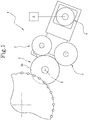
Figure 1 schematically represents the cutting device according to this invention; -
Figures 2A-2B are detail views showing two possible embodiments of an adjustment operation performed by the device according to this invention. - The
reference numeral 1 in the accompanying drawing generically denotes a cutting device of the tobacco industry, hereinafter in this description simply referred to as "device 1". In the embodiment illustrated, thedevice 1 is applied on a drum for transversely feeding a succession of rod-shaped semi-products (rod sections) and forming part of a filter tip attachment machine. - More specifically, the
device 1 comprises a rotary cutting member 2 (for example, a cutting disc 2), at least oneabrasive element 3, first motor means, second motor means 4 and anadjustment unit 5. - The
rotary cutting member 2 is configured to make a transverse cut on a bar- or rod-shaped semi-product of the tobacco industry. More in detail, therotary cutting member 2 has a circularperipheral portion 2a with a sharp cutting edge and configured to engage and cut the semi-products. - The
rotary cutting member 2 is driven by first motor means associated therewith to drive it in rotation about its axis of rotation X. - The
peripheral portion 2a of therotary cutting member 2 is kept sharp by the at least oneabrasive element 3 which is adapted to engage theperipheral portion 2a while therotary cutting member 2 is being used. - More specifically, the
abrasive element 3 is driven (by actuating means of known type, hence not illustrated) according to a sharpening motion by which it is made to slide against theperipheral portion 2a of therotary cutting member 2 in such a way that the pressure between the two promotes the sharpening process. - In other words, the actuating means are configured to keep the
abrasive element 3 and therotary cutting member 2 in contact with each other. - Preferably, the
abrasive element 3 comprises a grinding disc configured to be driven in rotation about its central axis to sharpen therotary cutting member 2. - Advantageously, the use of a grinding disc allows optimizing the sharpening process in that the disc wears down uniformly and has a constant behaviour for its entire working life.
- According to this aspect, the sharpening motion is a rotational motion of the grinding disc about its axis, driven by the aforementioned second motor means 4.
- The use of a grinding disc driven in rotation also allows reducing the total thermal stress the
abrasive element 3 is subjected to. - According to a particular aspect of this invention, the grinding disc is movable towards and away from the
rotary cutting member 2, preferably in a direction at right angles to the axis of rotation of the rotary cutting member, under the action of the actuating means to produce a feed movement intended to compensate for the wear on the grinding disc itself and/or on therotary cutting member 2. - More specifically, the actuating means are configured to move the grinding disc towards and away from the
rotary cutting member 2 in a transverse direction, preferably at right angles to the axis of rotation X of the rotary cutting member 2 (Figures 2A and 2B ). - In an embodiment in which the
rotary cutting member 2 has a V-shaped cutting edge, as shown schematically inFigure 2A , thedevice 1 comprises twoabrasive elements 3 acting on respective opposite surfaces of the V-shaped cutting edge and each driven in rotation by respective second motor means, preferably controllable independently of each other. - In this context, the actuating means are associated with each of the
abrasive elements 3 and are configured to move them simultaneously or independently according to a feed movement towards theperipheral portion 2a of therotary cutting member 2. In particular, the actuating means operate independently in the case where the twoabrasive elements 3 are mounted on respective, distinct slides or simultaneously on both theabrasive elements 3 in the case where they are mounted on a single slide. - In the different configuration shown in
Figure 2B , on the other hand, there is a singleabrasive element 3 to operate on a single lateral surface of therotary cutting member 2. The singleabrasive element 3 may be mounted on a single slide and driven by corresponding actuating means not illustrated. - According to the invention, the
adjustment unit 5 is connected to the first motor means and/or the second motor means 4 and is configured to detect directly or indirectly the electric power absorbed by the first motor means and/or by the second motor means 4 and to drive the actuating means as a function of the absorbed electric power detected in order to keep theabrasive element 3 and therotary cutting member 2 in contact with each other at a contact pressure whose value is within a predetermined interval. In other words, the adjustment unit continuously measures the power that is used to drive theabrasive element 3 in rotation about its axis, hence to overcome the resistance created by the contact between the grinding disc and therotary cutting member 2 and uses this information to determine whether or not it is necessary to activate the actuating means to move theabrasive element 3 closer to therotary cutting member 2 and, if it is, to determine the extent and/or the frequency of the steps by which to feed theabrasive element 3, in particular along the axis of the grinding disc. - Operatively, the pressure generated between the
rotary cutting member 2 and theabrasive element 3 during the sharpening process produces an increase in the power required to keep the abrasive element moving. - Therefore, if the power delivered by the motor means 4 drops below a certain threshold, it means the pressure between the
rotary cutting member 2 and theabrasive element 3 has fallen on account of progressive wear on the former and/or the latter, which in turn means that the sharpening process is becoming less effective. - On detecting this drop, the
adjustment unit 5 accordingly activates the actuating means to move theabrasive element 3 towards therotary cutting member 2 until the pressure between them returns to the right level to ensure optimum sharpening performance. - If there is more than one
abrasive element 3, theadjustment unit 5 is configured to activate the actuating means selectively as a function of the power absorbed by the second actuating means 4 associated with the sameabrasive element 3, so as to move, when necessary, only the specificabrasive elements 3 which are no longer in the optimum sharpening position relative to therotary cutting member 2 on account of progressive wear. - Preferably, the adjustment unit is configured to move the at least one
abrasive element 3 discretely: that is to say, in steps of suitably predetermined length. - In other words, each time the
adjustment unit 5 detects that the value of the power delivered by the motor means 4 indicates that therotary cutting member 2 and theabrasive element 3 are not close enough together, it activates the actuating means associated with theabrasive element 3 to move theabrasive element 3 by a specific distance towards therotary cutting member 2. - More specifically, this distance and/or a respective feed frequency is determined (preferably continuously or at specific time intervals) as a function of the instantaneous value of the absorbed power measured by the
adjustment unit 5. - In a first possible embodiment, the
adjustment unit 5 is configured to measure the instantaneous power of the second motor means 4 based on the electric power they absorb. - Alternatively, in a different embodiment, the
adjustment unit 5 is configured to measure the instantaneous power of the second motor means 4 based on their values of resistant torque and angular speed. - In a different embodiment, not illustrated, the drive power from the actuating means may be applied on the cutting member and not on the abrasive element. This is the case, preferably, where the cutting device is used for cutting a continuous strand or rod in a machine for making rod-shaped semi-products. In effect, under these circumstances, the cutting member comprises a rotary blade holder on which there are mounted two or more radial blades which may be fed in a radial direction in a controlled manner defining a radial feed system to all intents and purposes.
- In yet another embodiment, not illustrated, the drive power from the actuating means may be applied on both the cutting member and on the abrasive element, simultaneously for example.
- Advantageously, this invention achieves the aim of overcoming the abovementioned drawbacks of the prior art by providing a
cutting device 1 which operates efficiently and in optimum manner at all times because therotary cutting member 2 is always properly sharpened. - In effect, the
abrasive element 3 is driven by the motor means 4, under the control of theadjustment unit 5, so that it is always correctly positioned to perform the sharpening operation in the best possible manner. This control is based on the instantaneous power requirement of the abrasive element, which is substantially equal to the power absorbed by the contact between therotary cutting member 2 and the abrasive element and thus optimally approximates this value. In effect, the abrasive element (with the exception of its rotary supporting means) is not subject to other power losses that would alter the estimate of the power it absorbs when it comes into contact with therotary cutting member 2, since the abrasive element comes into contact only with therotary cutting member 2. - Also an object of this invention is a machine for making or processing bar- or rod-shaped semi-products of the tobacco industry, comprising a cutting device according to this invention.
- Another object of this invention is a method for sharpening a
rotary cutting member 2 of a cutting device of the tobacco industry. - More specifically, the method described herein may be used to sharpen a cutting device having one or more of the features described in the foregoing. The method comprises detecting directly or indirectly the electric power absorbed by the first motor means and/or by the second motor means 4.
- As a function of the absorbed electric power detected, the actuating means are driven to move the
abrasive element 3 and therotary cutting member 2 relative to each other in order to keep theabrasive element 3 and therotary cutting member 2 in contact with each other at a contact pressure whose value is within a predetermined interval. - The adjusting action is thus very precise because it can be set as a function of the power actually absorbed by the sharpening action, measurable independently of the braking action applied by cutting.
Claims (9)
- A cutting device of the tobacco industry, comprising:- a rotary cutting member (2) configured to make a transverse cut on a bar- or rod-shaped semi-product of the tobacco industry;- at least one abrasive element (3) adapted to engage and sharpen a peripheral cutting portion (2a) of the rotary cutting member (2);- first motor means, associated with the rotary cutting member (2) to set the rotary cutting member (2) in rotation about its axis of rotation (X);- second motor means (4), associated with the abrasive element (3) to set the abrasive element (3) in rotation about its axis of rotation;- actuating means associated with the abrasive element (3) and/or with the rotary cutting member (2) to keep the abrasive element (3) and the rotary cutting member (2) in contact with each other;characterized in that it comprises an adjustment unit (5) connected to the first motor means and/or the second motor means (4) and configured to detect directly or indirectly the electric power absorbed by the first motor means and/or by the second motor means (4) and to drive the actuating means as a function of the absorbed electric power detected in order to keep the abrasive element (3) and the rotary cutting member (2) in contact with each other at a contact pressure whose value is within a predetermined interval.
- The device according to claim 1, comprising two abrasive elements (3) configured to engage respective, axially opposed peripheral cutting portions of the rotary cutting member (2).
- The device according to claim 2, wherein the actuating means are associated with the two abrasive elements (3) and are configured to independently adjust the contact pressure between each abrasive element (3) and the rotary cutting member (2).
- The device according to one or more of the preceding claims, wherein the abrasive element (3) comprises a grinding disc.
- The device according to claim 4, wherein the actuating means are configured to move the grinding disc towards and away from the rotary cutting member (2) in a direction at right angles to the axis of rotation (X) of the rotary cutting member (2).
- A machine for making or processing bar- or rod-shaped semi-products of the tobacco industry, comprising a cutting device (1) according to one or more of the preceding claims.
- A method for sharpening a rotary cutting member (2) of a cutting device of the tobacco industry according to one or more of the preceding claims, comprising the following steps:- detecting directly or indirectly the electric power absorbed by the first motor means and/or by the second motor means (4);- driving the actuating means as a function of the absorbed electric power detected to move the abrasive element (3) and the rotary cutting member (2) relative to each other in order to keep the abrasive element (3) and the rotary cutting member (2) in contact with each other at a contact pressure whose value is within a predetermined interval.
- The method according to claim 7, wherein the step of detecting directly or indirectly the electric power absorbed by the first motor means and/or by the second motor means (4) is accomplished by detecting the instantaneous power absorbed by the second motor means (4) associated with the abrasive element (3).
- The method according to claim 8, wherein the step of detecting the instantaneous power absorbed by the second motor means (4) is carried out by measuring the instantaneous electric current absorbed by the second motor means (4).
Applications Claiming Priority (1)
| Application Number | Priority Date | Filing Date | Title |
|---|---|---|---|
| IT102019000024220A IT201900024220A1 (en) | 2019-12-17 | 2019-12-17 | Tobacco industry cutting device |
Publications (2)
| Publication Number | Publication Date |
|---|---|
| EP3838003A1 true EP3838003A1 (en) | 2021-06-23 |
| EP3838003B1 EP3838003B1 (en) | 2022-09-07 |
Family
ID=70155088
Family Applications (1)
| Application Number | Title | Priority Date | Filing Date |
|---|---|---|---|
| EP20207783.0A Active EP3838003B1 (en) | 2019-12-17 | 2020-11-16 | Cutting device of the tobacco industry |
Country Status (3)
| Country | Link |
|---|---|
| EP (1) | EP3838003B1 (en) |
| IT (1) | IT201900024220A1 (en) |
| PL (1) | PL3838003T3 (en) |
Cited By (1)
| Publication number | Priority date | Publication date | Assignee | Title |
|---|---|---|---|---|
| IT202200026361A1 (en) * | 2022-12-21 | 2024-06-21 | Gd Spa | MACHINE FOR PROCESSING BARS |
Citations (4)
| Publication number | Priority date | Publication date | Assignee | Title |
|---|---|---|---|---|
| GB2123324A (en) * | 1982-07-14 | 1984-02-01 | Gd Spa | A device for sharpening rotating blades |
| EP2030515A2 (en) * | 2007-08-31 | 2009-03-04 | Hauni Maschinenbau AG | Method and device for grinding cutting blades |
| EP2524608A2 (en) | 2011-05-20 | 2012-11-21 | Hauni Maschinenbau AG | Cutting device for a rod-making machine for the tobacco processing industry and method for adjusting the position of the or each grinding wheel of a device for grinding in a cutting device for a rod-making machine for the tobacco processing industry |
| EP3366439A1 (en) * | 2017-02-27 | 2018-08-29 | Bizerba SE & Co. KG | Slicer with a device for supervising the condition of the knife |
-
2019
- 2019-12-17 IT IT102019000024220A patent/IT201900024220A1/en unknown
-
2020
- 2020-11-16 PL PL20207783.0T patent/PL3838003T3/en unknown
- 2020-11-16 EP EP20207783.0A patent/EP3838003B1/en active Active
Patent Citations (4)
| Publication number | Priority date | Publication date | Assignee | Title |
|---|---|---|---|---|
| GB2123324A (en) * | 1982-07-14 | 1984-02-01 | Gd Spa | A device for sharpening rotating blades |
| EP2030515A2 (en) * | 2007-08-31 | 2009-03-04 | Hauni Maschinenbau AG | Method and device for grinding cutting blades |
| EP2524608A2 (en) | 2011-05-20 | 2012-11-21 | Hauni Maschinenbau AG | Cutting device for a rod-making machine for the tobacco processing industry and method for adjusting the position of the or each grinding wheel of a device for grinding in a cutting device for a rod-making machine for the tobacco processing industry |
| EP3366439A1 (en) * | 2017-02-27 | 2018-08-29 | Bizerba SE & Co. KG | Slicer with a device for supervising the condition of the knife |
Cited By (2)
| Publication number | Priority date | Publication date | Assignee | Title |
|---|---|---|---|---|
| IT202200026361A1 (en) * | 2022-12-21 | 2024-06-21 | Gd Spa | MACHINE FOR PROCESSING BARS |
| EP4393324A1 (en) * | 2022-12-21 | 2024-07-03 | G.D S.p.A. | Machine for manufacturing rods |
Also Published As
| Publication number | Publication date |
|---|---|
| EP3838003B1 (en) | 2022-09-07 |
| PL3838003T3 (en) | 2022-12-27 |
| IT201900024220A1 (en) | 2021-06-17 |
Similar Documents
| Publication | Publication Date | Title |
|---|---|---|
| US9308663B2 (en) | Method for cutting blade control system, particularly for cutting-off machines for cutting logs of web material | |
| EP1110683B1 (en) | Method and apparatus for resurfacing anvil blanket of a rotary diecutter for box making machine | |
| JPH03221361A (en) | Device for polishing rotary knife | |
| CN102783709A (en) | Cutting device for a rod-making machine and method for adjusting the position of the or each grinding wheel of a device for grinding in a cutting device for a rod-making machine | |
| EP3838003B1 (en) | Cutting device of the tobacco industry | |
| CN101376224B (en) | Method and device for grinding cutting blades | |
| US9474302B2 (en) | Cutting and grinding apparatus, method of manufacture of cut lengths of tobacco, and method for controlling the operation of a cutting apparatus | |
| EP2957184B1 (en) | Adjustment apparatus | |
| CN102196735B (en) | cutting device | |
| EP2965638A1 (en) | Knife positioning apparatus | |
| US6638142B2 (en) | Apparatus for sharpening blades | |
| CN109259301B (en) | Device for cutting rod-shaped articles and machine having such a device | |
| CN114343225B (en) | Method for automatically adjusting knife gate gap of tobacco cutting machine on tobacco cutting line | |
| WO2022002763A1 (en) | Control method for controlling the process of sharpening of a cutting blade in a cutting machine | |
| US20220362959A1 (en) | Cutting machine for transversely cutting logs of paper material | |
| US20240109218A1 (en) | Cutting-off machine for the transversal cutting of logs of paper material | |
| JP2011130769A (en) | Cutting device, and cutting knife for cutting rod-like product in tobacco processing industry | |
| EP4393324A1 (en) | Machine for manufacturing rods | |
| EP1681135A1 (en) | Blade sharpening machines | |
| GB2425979A (en) | Dressing the blades of a tobacco cutting apparatus | |
| CN118927313A (en) | Axial cutting machine | |
| CA2268921A1 (en) | Device for rotational cutting of band-shaped material |
Legal Events
| Date | Code | Title | Description |
|---|---|---|---|
| PUAI | Public reference made under article 153(3) epc to a published international application that has entered the european phase |
Free format text: ORIGINAL CODE: 0009012 |
|
| STAA | Information on the status of an ep patent application or granted ep patent |
Free format text: STATUS: THE APPLICATION HAS BEEN PUBLISHED |
|
| AK | Designated contracting states |
Kind code of ref document: A1 Designated state(s): AL AT BE BG CH CY CZ DE DK EE ES FI FR GB GR HR HU IE IS IT LI LT LU LV MC MK MT NL NO PL PT RO RS SE SI SK SM TR |
|
| STAA | Information on the status of an ep patent application or granted ep patent |
Free format text: STATUS: REQUEST FOR EXAMINATION WAS MADE |
|
| 17P | Request for examination filed |
Effective date: 20211207 |
|
| RBV | Designated contracting states (corrected) |
Designated state(s): AL AT BE BG CH CY CZ DE DK EE ES FI FR GB GR HR HU IE IS IT LI LT LU LV MC MK MT NL NO PL PT RO RS SE SI SK SM TR |
|
| GRAP | Despatch of communication of intention to grant a patent |
Free format text: ORIGINAL CODE: EPIDOSNIGR1 |
|
| STAA | Information on the status of an ep patent application or granted ep patent |
Free format text: STATUS: GRANT OF PATENT IS INTENDED |
|
| INTG | Intention to grant announced |
Effective date: 20220329 |
|
| GRAS | Grant fee paid |
Free format text: ORIGINAL CODE: EPIDOSNIGR3 |
|
| GRAA | (expected) grant |
Free format text: ORIGINAL CODE: 0009210 |
|
| STAA | Information on the status of an ep patent application or granted ep patent |
Free format text: STATUS: THE PATENT HAS BEEN GRANTED |
|
| AK | Designated contracting states |
Kind code of ref document: B1 Designated state(s): AL AT BE BG CH CY CZ DE DK EE ES FI FR GB GR HR HU IE IS IT LI LT LU LV MC MK MT NL NO PL PT RO RS SE SI SK SM TR |
|
| REG | Reference to a national code |
Ref country code: GB Ref legal event code: FG4D |
|
| REG | Reference to a national code |
Ref country code: CH Ref legal event code: EP Ref country code: AT Ref legal event code: REF Ref document number: 1516317 Country of ref document: AT Kind code of ref document: T Effective date: 20220915 |
|
| REG | Reference to a national code |
Ref country code: DE Ref legal event code: R096 Ref document number: 602020004983 Country of ref document: DE |
|
| REG | Reference to a national code |
Ref country code: IE Ref legal event code: FG4D |
|
| REG | Reference to a national code |
Ref country code: NL Ref legal event code: FP |
|
| REG | Reference to a national code |
Ref country code: LT Ref legal event code: MG9D |
|
| PG25 | Lapsed in a contracting state [announced via postgrant information from national office to epo] |
Ref country code: SE Free format text: LAPSE BECAUSE OF FAILURE TO SUBMIT A TRANSLATION OF THE DESCRIPTION OR TO PAY THE FEE WITHIN THE PRESCRIBED TIME-LIMIT Effective date: 20220907 Ref country code: RS Free format text: LAPSE BECAUSE OF FAILURE TO SUBMIT A TRANSLATION OF THE DESCRIPTION OR TO PAY THE FEE WITHIN THE PRESCRIBED TIME-LIMIT Effective date: 20220907 Ref country code: NO Free format text: LAPSE BECAUSE OF FAILURE TO SUBMIT A TRANSLATION OF THE DESCRIPTION OR TO PAY THE FEE WITHIN THE PRESCRIBED TIME-LIMIT Effective date: 20221207 Ref country code: LV Free format text: LAPSE BECAUSE OF FAILURE TO SUBMIT A TRANSLATION OF THE DESCRIPTION OR TO PAY THE FEE WITHIN THE PRESCRIBED TIME-LIMIT Effective date: 20220907 Ref country code: LT Free format text: LAPSE BECAUSE OF FAILURE TO SUBMIT A TRANSLATION OF THE DESCRIPTION OR TO PAY THE FEE WITHIN THE PRESCRIBED TIME-LIMIT Effective date: 20220907 Ref country code: FI Free format text: LAPSE BECAUSE OF FAILURE TO SUBMIT A TRANSLATION OF THE DESCRIPTION OR TO PAY THE FEE WITHIN THE PRESCRIBED TIME-LIMIT Effective date: 20220907 |
|
| REG | Reference to a national code |
Ref country code: AT Ref legal event code: MK05 Ref document number: 1516317 Country of ref document: AT Kind code of ref document: T Effective date: 20220907 |
|
| PG25 | Lapsed in a contracting state [announced via postgrant information from national office to epo] |
Ref country code: HR Free format text: LAPSE BECAUSE OF FAILURE TO SUBMIT A TRANSLATION OF THE DESCRIPTION OR TO PAY THE FEE WITHIN THE PRESCRIBED TIME-LIMIT Effective date: 20220907 Ref country code: GR Free format text: LAPSE BECAUSE OF FAILURE TO SUBMIT A TRANSLATION OF THE DESCRIPTION OR TO PAY THE FEE WITHIN THE PRESCRIBED TIME-LIMIT Effective date: 20221208 |
|
| PG25 | Lapsed in a contracting state [announced via postgrant information from national office to epo] |
Ref country code: SM Free format text: LAPSE BECAUSE OF FAILURE TO SUBMIT A TRANSLATION OF THE DESCRIPTION OR TO PAY THE FEE WITHIN THE PRESCRIBED TIME-LIMIT Effective date: 20220907 Ref country code: RO Free format text: LAPSE BECAUSE OF FAILURE TO SUBMIT A TRANSLATION OF THE DESCRIPTION OR TO PAY THE FEE WITHIN THE PRESCRIBED TIME-LIMIT Effective date: 20220907 Ref country code: PT Free format text: LAPSE BECAUSE OF FAILURE TO SUBMIT A TRANSLATION OF THE DESCRIPTION OR TO PAY THE FEE WITHIN THE PRESCRIBED TIME-LIMIT Effective date: 20230109 Ref country code: ES Free format text: LAPSE BECAUSE OF FAILURE TO SUBMIT A TRANSLATION OF THE DESCRIPTION OR TO PAY THE FEE WITHIN THE PRESCRIBED TIME-LIMIT Effective date: 20220907 Ref country code: CZ Free format text: LAPSE BECAUSE OF FAILURE TO SUBMIT A TRANSLATION OF THE DESCRIPTION OR TO PAY THE FEE WITHIN THE PRESCRIBED TIME-LIMIT Effective date: 20220907 Ref country code: AT Free format text: LAPSE BECAUSE OF FAILURE TO SUBMIT A TRANSLATION OF THE DESCRIPTION OR TO PAY THE FEE WITHIN THE PRESCRIBED TIME-LIMIT Effective date: 20220907 |
|
| PG25 | Lapsed in a contracting state [announced via postgrant information from national office to epo] |
Ref country code: SK Free format text: LAPSE BECAUSE OF FAILURE TO SUBMIT A TRANSLATION OF THE DESCRIPTION OR TO PAY THE FEE WITHIN THE PRESCRIBED TIME-LIMIT Effective date: 20220907 Ref country code: IS Free format text: LAPSE BECAUSE OF FAILURE TO SUBMIT A TRANSLATION OF THE DESCRIPTION OR TO PAY THE FEE WITHIN THE PRESCRIBED TIME-LIMIT Effective date: 20230107 Ref country code: EE Free format text: LAPSE BECAUSE OF FAILURE TO SUBMIT A TRANSLATION OF THE DESCRIPTION OR TO PAY THE FEE WITHIN THE PRESCRIBED TIME-LIMIT Effective date: 20220907 |
|
| REG | Reference to a national code |
Ref country code: DE Ref legal event code: R097 Ref document number: 602020004983 Country of ref document: DE |
|
| PG25 | Lapsed in a contracting state [announced via postgrant information from national office to epo] |
Ref country code: MC Free format text: LAPSE BECAUSE OF FAILURE TO SUBMIT A TRANSLATION OF THE DESCRIPTION OR TO PAY THE FEE WITHIN THE PRESCRIBED TIME-LIMIT Effective date: 20220907 Ref country code: AL Free format text: LAPSE BECAUSE OF FAILURE TO SUBMIT A TRANSLATION OF THE DESCRIPTION OR TO PAY THE FEE WITHIN THE PRESCRIBED TIME-LIMIT Effective date: 20220907 |
|
| P01 | Opt-out of the competence of the unified patent court (upc) registered |
Effective date: 20230528 |
|
| PLBE | No opposition filed within time limit |
Free format text: ORIGINAL CODE: 0009261 |
|
| STAA | Information on the status of an ep patent application or granted ep patent |
Free format text: STATUS: NO OPPOSITION FILED WITHIN TIME LIMIT |
|
| REG | Reference to a national code |
Ref country code: BE Ref legal event code: MM Effective date: 20221130 |
|
| PG25 | Lapsed in a contracting state [announced via postgrant information from national office to epo] |
Ref country code: DK Free format text: LAPSE BECAUSE OF FAILURE TO SUBMIT A TRANSLATION OF THE DESCRIPTION OR TO PAY THE FEE WITHIN THE PRESCRIBED TIME-LIMIT Effective date: 20220907 |
|
| 26N | No opposition filed |
Effective date: 20230608 |
|
| PG25 | Lapsed in a contracting state [announced via postgrant information from national office to epo] |
Ref country code: SI Free format text: LAPSE BECAUSE OF FAILURE TO SUBMIT A TRANSLATION OF THE DESCRIPTION OR TO PAY THE FEE WITHIN THE PRESCRIBED TIME-LIMIT Effective date: 20220907 Ref country code: LU Free format text: LAPSE BECAUSE OF NON-PAYMENT OF DUE FEES Effective date: 20221116 |
|
| PG25 | Lapsed in a contracting state [announced via postgrant information from national office to epo] |
Ref country code: IE Free format text: LAPSE BECAUSE OF NON-PAYMENT OF DUE FEES Effective date: 20221116 |
|
| PG25 | Lapsed in a contracting state [announced via postgrant information from national office to epo] |
Ref country code: FR Free format text: LAPSE BECAUSE OF NON-PAYMENT OF DUE FEES Effective date: 20221130 Ref country code: BE Free format text: LAPSE BECAUSE OF NON-PAYMENT OF DUE FEES Effective date: 20221130 |
|
| PG25 | Lapsed in a contracting state [announced via postgrant information from national office to epo] |
Ref country code: CY Free format text: LAPSE BECAUSE OF FAILURE TO SUBMIT A TRANSLATION OF THE DESCRIPTION OR TO PAY THE FEE WITHIN THE PRESCRIBED TIME-LIMIT Effective date: 20220907 |
|
| PG25 | Lapsed in a contracting state [announced via postgrant information from national office to epo] |
Ref country code: MK Free format text: LAPSE BECAUSE OF FAILURE TO SUBMIT A TRANSLATION OF THE DESCRIPTION OR TO PAY THE FEE WITHIN THE PRESCRIBED TIME-LIMIT Effective date: 20220907 Ref country code: IT Free format text: LAPSE BECAUSE OF FAILURE TO SUBMIT A TRANSLATION OF THE DESCRIPTION OR TO PAY THE FEE WITHIN THE PRESCRIBED TIME-LIMIT Effective date: 20220907 |
|
| PG25 | Lapsed in a contracting state [announced via postgrant information from national office to epo] |
Ref country code: TR Free format text: LAPSE BECAUSE OF FAILURE TO SUBMIT A TRANSLATION OF THE DESCRIPTION OR TO PAY THE FEE WITHIN THE PRESCRIBED TIME-LIMIT Effective date: 20220907 |
|
| REG | Reference to a national code |
Ref country code: CH Ref legal event code: PL |
|
| PG25 | Lapsed in a contracting state [announced via postgrant information from national office to epo] |
Ref country code: CH Free format text: LAPSE BECAUSE OF NON-PAYMENT OF DUE FEES Effective date: 20231130 |
|
| PG25 | Lapsed in a contracting state [announced via postgrant information from national office to epo] |
Ref country code: HU Free format text: LAPSE BECAUSE OF FAILURE TO SUBMIT A TRANSLATION OF THE DESCRIPTION OR TO PAY THE FEE WITHIN THE PRESCRIBED TIME-LIMIT; INVALID AB INITIO Effective date: 20201116 Ref country code: CH Free format text: LAPSE BECAUSE OF NON-PAYMENT OF DUE FEES Effective date: 20231130 Ref country code: BG Free format text: LAPSE BECAUSE OF FAILURE TO SUBMIT A TRANSLATION OF THE DESCRIPTION OR TO PAY THE FEE WITHIN THE PRESCRIBED TIME-LIMIT Effective date: 20220907 |
|
| PG25 | Lapsed in a contracting state [announced via postgrant information from national office to epo] |
Ref country code: MT Free format text: LAPSE BECAUSE OF FAILURE TO SUBMIT A TRANSLATION OF THE DESCRIPTION OR TO PAY THE FEE WITHIN THE PRESCRIBED TIME-LIMIT Effective date: 20220907 |
|
| GBPC | Gb: european patent ceased through non-payment of renewal fee |
Effective date: 20241116 |
|
| PG25 | Lapsed in a contracting state [announced via postgrant information from national office to epo] |
Ref country code: GB Free format text: LAPSE BECAUSE OF NON-PAYMENT OF DUE FEES Effective date: 20241116 |
|
| PGFP | Annual fee paid to national office [announced via postgrant information from national office to epo] |
Ref country code: NL Payment date: 20251126 Year of fee payment: 6 |
|
| PGFP | Annual fee paid to national office [announced via postgrant information from national office to epo] |
Ref country code: DE Payment date: 20251128 Year of fee payment: 6 |
|
| PGFP | Annual fee paid to national office [announced via postgrant information from national office to epo] |
Ref country code: PL Payment date: 20251106 Year of fee payment: 6 |
|
| PG25 | Lapsed in a contracting state [announced via postgrant information from national office to epo] |
Ref country code: CH Free format text: THE PATENT HAS BEEN ANNULLED BY A DECISION OF A NATIONAL AUTHORITY Effective date: 20231130 |