EP3837958A1 - Verfahren zum antreiben einer landwirtschaftlichen arbeitsmaschine - Google Patents
Verfahren zum antreiben einer landwirtschaftlichen arbeitsmaschine Download PDFInfo
- Publication number
- EP3837958A1 EP3837958A1 EP20200683.9A EP20200683A EP3837958A1 EP 3837958 A1 EP3837958 A1 EP 3837958A1 EP 20200683 A EP20200683 A EP 20200683A EP 3837958 A1 EP3837958 A1 EP 3837958A1
- Authority
- EP
- European Patent Office
- Prior art keywords
- engine
- units
- load
- driven
- full load
- Prior art date
- Legal status (The legal status is an assumption and is not a legal conclusion. Google has not performed a legal analysis and makes no representation as to the accuracy of the status listed.)
- Pending
Links
- 238000000034 method Methods 0.000 title claims abstract description 22
- 238000002485 combustion reaction Methods 0.000 claims description 5
- 238000004140 cleaning Methods 0.000 claims description 4
- 230000002706 hydrostatic effect Effects 0.000 claims description 4
- 238000000926 separation method Methods 0.000 description 5
- 238000003306 harvesting Methods 0.000 description 4
- 239000000446 fuel Substances 0.000 description 3
- 241001124569 Lycaenidae Species 0.000 description 2
- 230000000712 assembly Effects 0.000 description 1
- 238000000429 assembly Methods 0.000 description 1
- 230000005540 biological transmission Effects 0.000 description 1
- 239000002826 coolant Substances 0.000 description 1
- 230000007423 decrease Effects 0.000 description 1
- 238000006073 displacement reaction Methods 0.000 description 1
- 239000003344 environmental pollutant Substances 0.000 description 1
- 239000003337 fertilizer Substances 0.000 description 1
- 239000004459 forage Substances 0.000 description 1
- 238000002347 injection Methods 0.000 description 1
- 239000007924 injection Substances 0.000 description 1
- 239000000203 mixture Substances 0.000 description 1
- 231100000719 pollutant Toxicity 0.000 description 1
- 230000008092 positive effect Effects 0.000 description 1
- 239000000243 solution Substances 0.000 description 1
- 239000010902 straw Substances 0.000 description 1
Images


Classifications
-
- A—HUMAN NECESSITIES
- A01—AGRICULTURE; FORESTRY; ANIMAL HUSBANDRY; HUNTING; TRAPPING; FISHING
- A01D—HARVESTING; MOWING
- A01D41/00—Combines, i.e. harvesters or mowers combined with threshing devices
- A01D41/12—Details of combines
- A01D41/127—Control or measuring arrangements specially adapted for combines
- A01D41/1274—Control or measuring arrangements specially adapted for combines for drives
-
- A—HUMAN NECESSITIES
- A01—AGRICULTURE; FORESTRY; ANIMAL HUSBANDRY; HUNTING; TRAPPING; FISHING
- A01D—HARVESTING; MOWING
- A01D43/00—Mowers combined with apparatus performing additional operations while mowing
- A01D43/08—Mowers combined with apparatus performing additional operations while mowing with means for cutting up the mown crop, e.g. forage harvesters
- A01D43/085—Control or measuring arrangements specially adapted therefor
-
- F—MECHANICAL ENGINEERING; LIGHTING; HEATING; WEAPONS; BLASTING
- F02—COMBUSTION ENGINES; HOT-GAS OR COMBUSTION-PRODUCT ENGINE PLANTS
- F02D—CONTROLLING COMBUSTION ENGINES
- F02D29/00—Controlling engines, such controlling being peculiar to the devices driven thereby, the devices being other than parts or accessories essential to engine operation, e.g. controlling of engines by signals external thereto
- F02D29/02—Controlling engines, such controlling being peculiar to the devices driven thereby, the devices being other than parts or accessories essential to engine operation, e.g. controlling of engines by signals external thereto peculiar to engines driving vehicles; peculiar to engines driving variable pitch propellers
-
- F—MECHANICAL ENGINEERING; LIGHTING; HEATING; WEAPONS; BLASTING
- F02—COMBUSTION ENGINES; HOT-GAS OR COMBUSTION-PRODUCT ENGINE PLANTS
- F02D—CONTROLLING COMBUSTION ENGINES
- F02D41/00—Electrical control of supply of combustible mixture or its constituents
- F02D41/02—Circuit arrangements for generating control signals
- F02D41/021—Introducing corrections for particular conditions exterior to the engine
-
- F—MECHANICAL ENGINEERING; LIGHTING; HEATING; WEAPONS; BLASTING
- F02—COMBUSTION ENGINES; HOT-GAS OR COMBUSTION-PRODUCT ENGINE PLANTS
- F02D—CONTROLLING COMBUSTION ENGINES
- F02D41/00—Electrical control of supply of combustible mixture or its constituents
- F02D41/02—Circuit arrangements for generating control signals
- F02D41/04—Introducing corrections for particular operating conditions
-
- F—MECHANICAL ENGINEERING; LIGHTING; HEATING; WEAPONS; BLASTING
- F02—COMBUSTION ENGINES; HOT-GAS OR COMBUSTION-PRODUCT ENGINE PLANTS
- F02D—CONTROLLING COMBUSTION ENGINES
- F02D2250/00—Engine control related to specific problems or objectives
- F02D2250/18—Control of the engine output torque
- F02D2250/22—Control of the engine output torque by keeping a torque reserve, i.e. with temporarily reduced drive train or engine efficiency
Definitions
- the invention relates to a method for driving an agricultural work machine with a traction drive and units by means of a prime mover, wherein in different operating modes of the work machine the traction drive and the units are each driven or non-drive in different combinations, the units are driven in a limited speed range of the prime mover, and depending on the load, the engine is switched between a full-load stage with maximum power and a plurality of part-load stages with an output that is gradually reduced compared to the full-load stage.
- Agricultural machines are, for example, combine harvesters, forage harvesters or tractors with attachments such as fertilizer spreaders, seed drills, sprayers, tedders or rakes.
- attachments such as fertilizer spreaders, seed drills, sprayers, tedders or rakes.
- many work processes run completely or partially automatically, including the operation and control of a large part of the units of the work machine.
- Units are components of the work machine that support or perform agricultural work and thus consume power, for example a harvesting header such as a reel or cutting unit or the front lifting gear for raising and lowering such attachments, a separating unit, a threshing drum, a cleaning fan, a swath, a chopper or a grain tank emptying unit .
- the engine of such a work machine is in particular a diesel engine as a common drive for the units and the drive.
- the power output by the engine is therefore partly supplied to the traction drive and partly to the units driven in the current operating mode. Since the power requirement of a unit varies, for example during the harvest, the power output by the engine is automatically adapted. The difference available up to the maximum power of the engine is available for the travel drive.
- the units of such a work machine are typically driven directly by the engine and thus limit its speed range.
- the engine can be operated in different load levels, in each of which it has a different performance curve.
- the load levels which can be infinitesimally small, differ in the course of the power depending on the speed of the output shaft of the prime mover and, in particular, in the maximum power that can be output by the prime mover.
- the full load level is the load level that can be selected by the user during operation, in which the motor delivers the highest output.
- the engine power in the full load stage does not necessarily correspond to the technically possible maximum power of the engine, but can be selected to be lower ("throttled").
- Generally known are working machines with engine power that is mechanically or by the control software throttled in the full load stage in order to optimize consumption and / or wear. It is also known to temporarily or permanently change the performance in the full load stage by intervening in the control software.
- the engine is switched between the load levels by means of a control device, for example by means of a transmission, or also by changing the injection quantity or changing the fuel mixture, in particular the combustion air ratio. Switching to a higher or lower load level takes place automatically if the required change in performance within the selected load level would exceed or fall below the permissible speed range.
- EP 3 259 975 A1 proposes, as part of a method for driving such a work machine, to group the load levels and to allow switching between load levels only within one group in order to reduce the fuel consumption and the pollutant emissions of the work machine.
- the invention is based on the object of protecting the units from overload.
- the engine can only be switched to the full load level in a full load mode and only to partial load levels in any other of the operating modes.
- the maximum motor power is limited depending on the working units so that the drives are not overloaded.
- In the full load mode at least one of the units is driven.
- these are aggregates that have a high Have power requirements, for example separation unit, swath deposit, chopper or grain tank emptying.
- the driving speed does not have to be reduced when units are switched on, as is necessary when overloading.
- the control of the engine along a narrow speed range is particularly advantageous in the combine, since the threshing and cleaning units are directly coupled to the engine speed and a constant speed has a positive effect on the work result.
- two of the units are preferably driven in full load mode.
- the full load mode is characterized by the simultaneous operation of two units, for example a chopper and grain tank emptying.
- the engine can preferably only be switched over to a high-load stage from the partial-load stages in full load mode and in at least one high load mode.
- a high-load level below full load also allows the associated units to be switched on while the driving speed is undiminished, but maintains the power reserve for full-load mode.
- the working machine is preferably a combine harvester and the units include a harvesting header, a threshing drum, a separating unit, a cleaning fan, a swath, a chopper and / or a grain tank emptying unit.
- the separation unit can be designed as a shaker or as a rotor separation unit. In particular, the rotor separation has a high power requirement.
- a travel speed of the travel drive is preferably controlled as a function of a crop harvested with the work machine (1).
- the parameters of the crop that influence the choice of driving speed are, in particular, the type, moisture, structure and density of the crop, as well as the quantity and throughput of the crop, but also the contour and cross-sectional area of the swath.
- the travel speed is preferably controlled as a function of the engine, the travel drive and / or at least one of the driven assemblies.
- the parameters of the engine, the drive system and the units that influence the choice of the driving speed are, in particular, the maximum torque and maximum power of the engine, the torque and speed of the units, in particular the chopping drum, displacement and pressure of a hydraulic converter, the fuel throughput and the coolant temperature one Internal combustion engine.
- the limited maximum engine power is communicated to the priority controller so that it regulates the driving speed to a value at which the limited maximum engine power is used.
- the engine preferably has an internal combustion engine and more preferably a hydrostatic converter.
- Work machines with internal combustion engines and in particular with hydrostatic converters are generally known.
- FIG. 1 shows an agricultural work machine 1 according to the invention in the form of a combine harvester (after Hans Wastlhuber, Wikimedia Commons).
- the work machine 1 is driven in a direction of travel 3 by means of a travel drive 2.
- a crop flow, not shown, of parts of plants is drawn into a harvesting attachment 4 and guided via a threshing drum 5a into a separating unit 5b - here: a tray shaker.
- the grain is deposited in a grain tank 6 and the threshed straw is removed by a chopper 7.
- An engine 8, not shown in detail, in the form of a diesel unit with a downstream hydrostatic converter drives the units and the travel drive 2.
- the engine 8 can be switched into different load levels, which differ in the amount of power that the engine 8 delivers as a function of the speed.
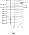
- the ones in the Figures 2 and 3 The performance curves shown describe the course of the performance relative to the speed for the respective load levels.
- the other figures each show a family of essentially parallel performance characteristics 9 of an engine 8, which the working machine according to a known from the prior art ( Figure 2 ) and according to a method according to the invention ( Figure 3 ) drives.
- the figures each show a full load characteristic curve 10 of the full load stage, in which the engine 8 delivers the maximum power of up to 581 kW , and several part load characteristics 11 of the part load stages, in which the engine 8 delivers a lower power in stages.
- the engine 8 In a limited speed range 12 between a minimum speed 13 of 1700 and a maximum speed 14 of 1879 rpm , the engine 8 is switched between the load levels depending on the actual power requirement of the travel drive 2 and the units.
- a control device not shown, ensures that the driving speed of the drive 2 remains constant: If the power requirement of the units increases and therefore the speed of the engine 8 falls below the minimum speed 13, then the control device automatically switches to the next higher load level, the power requirement decreases and increases the speed above the maximum speed 14, it switches to the next lower load level.
- the speed of the engine 8 is continuously determined by a speed sensor and displayed to a driver (not shown) of the work machine 1 in the driver's cab 15.
- a first high-load stage with a high-load characteristic curve 16 based on a minimum power 17 of 475 kW can only be switched in operating modes in which a swath (not shown) is driven.
- a second high-load stage with a high-load characteristic curve 18 based on a minimum power 19 of 505 kW can only be switched in operating modes in which either the chopper 7 or a grain tank emptying device 20 are driven.
- the full load level with the full load characteristic curve 10 based on a minimum power 21 of 530 kW can only be switched in an operating mode in which the chopper 7 and the grain tank emptying device 20 are driven at the same time.
Landscapes
- Engineering & Computer Science (AREA)
- Chemical & Material Sciences (AREA)
- Combustion & Propulsion (AREA)
- Mechanical Engineering (AREA)
- General Engineering & Computer Science (AREA)
- Life Sciences & Earth Sciences (AREA)
- Environmental Sciences (AREA)
- Combines (AREA)
- Control Of Vehicle Engines Or Engines For Specific Uses (AREA)
Abstract
Description
- Die Erfindung betrifft ein Verfahren zum Antreiben einer landwirtschaftlichen Arbeitsmaschine mit einem Fahrantrieb und Aggregaten mittels einer Kraftmaschine, wobei in unterschiedlichen Betriebsmodi der Arbeitsmaschine der Fahrantrieb und die Aggregate in unterschiedlichen Kombinationen jeweils angetrieben oder antriebslos sind, die Aggregate in einem begrenzten Drehzahlbereich der Kraftmaschine angetrieben werden, und die Kraftmaschine lastabhängig zwischen einer Volllaststufe mit maximaler Leistung und einer Mehrzahl von Teillaststufen mit gegenüber der Volllaststufe stufenweise reduzierter Leistung umgeschaltet wird.
- Landwirtschaftliche Arbeitsmaschinen sind beispielsweise Mähdrescher, Feldhäcksler oder Schlepper mit Anbauten wie Düngerstreuer, Sämaschinen, Spritzeinrichtungen, Wender oder Schwader. In solchen Arbeitsmaschinen laufen viele Arbeitsabläufe ganz oder teilweise automatisiert ab, unter anderem der Betrieb und die Steuerung eines Großteils der Aggregate der Arbeitsmaschine. Aggregate sind die landwirtschaftliche Arbeit unterstützende oder verrichtende und dadurch Leistung verbrauchende Komponenten der Arbeitsmaschine, beispielsweise ein Erntevorsatz wie Haspel oder Schneidwerk oder das Fronthubwerk zum Anheben und Absenken solcher Vorsatzgeräte, ein Abscheideaggregat, eine Dreschtrommel, ein Reinigungsgebläse, eine Schwadablage, ein Häcksler oder eine Korntankentleerung.
- Die Kraftmaschine einer solchen Arbeitsmaschine ist insbesondere ein Dieselmotor als gemeinsamer Antrieb für die Aggregate und den Fahrantrieb. Die von der Kraftmaschine abgegebene Leistung wird also zu einem Teil dem Fahrantrieb und zu einem anderen Teil den im jeweils aktuellen Betriebsmodus angetriebenen Aggregaten zugeführt. Da der Leistungsbedarf eines Aggregats beispielsweise während der Ernte variiert, wird die von der Kraftmaschine abgegebene Leistung automatisch angepasst. Die jeweils bis zu der maximalen Leistung der Kraftmaschine verfügbare Differenz steht für den Fahrantrieb zur Verfügung.
- Die Aggregate einer solchen Arbeitsmaschine werden typischer Weise unmittelbar über die Kraftmaschine angetrieben und beschränken damit deren Drehzahlbereich. Die Kraftmaschine ist in verschiedenen Laststufen betreibbar ist, in denen sie jeweils eine andere Leistungskennlinie hat. Die Laststufen, die infinitesimal klein sein können, unterscheiden sich jeweils im Verlauf der Leistung abhängig von der Drehzahl der Abtriebswelle der Kraftmaschine und insbesondere in der von der Kraftmaschine abgebbaren Maximalleistung.
- Die Volllaststufe ist die im Betrieb vom Anwender wählbare Laststufe, in der der Motor die höchste Leistung abgibt. Die Motorleistung in der Volllaststufe entspricht dabei nicht zwingend der technisch möglichen Maximalleistung des Motors, sondern kann gezielt niedriger gewählt ("gedrosselt") werden. Allgemein bekannt sind Arbeitsmaschinen mit in der Volllaststufe mechanisch oder durch die Steuerungssoftware gedrosselter Motorleistung, um Verbrauch und/oder Verschleiß zu optimieren. Weiterhin ist es bekannt, die Leistung in der Volllaststufe durch Eingriff in die Steuerungssoftware vorübergehend oder dauerhaft zu verändern.
- Die Kraftmaschine wird mittels einer Regeleinrichtung zwischen den Laststufen beispielsweise mittels eines Getriebes umgeschaltet, oder auch durch Änderung der Einspritzmenge oder Veränderung des Kraftstoffgemisches, insbesondere des Verbrennungsluftverhältnisses. Das Umschalten in eine höhere oder niedrigere Laststufe erfolgt automatisch, wenn die geforderte Leistungsänderung innerhalb der gewählten Laststufe den zulässigen Drehzahlbereich über- oder unterschreiten würde.
-
EP 3 259 975 A1 schlägt im Rahmen eines Verfahrens zum Antreiben einer solchen Arbeitsmaschine vor, die Laststufen zu gruppieren und das Umschalten zwischen Laststufen nur innerhalb einer Gruppe zuzulassen, um den Kraftstoffverbrauch und die Schadstoffemissionen der Arbeitsmaschine zu senken. - In den bekannten Arbeitsmaschinen kann die volle Motorleistung nicht in den Aggregaten genutzt werden. Einige Antriebe können nicht permanent die volle Motorleistung übertragen. Das Antriebskonzept muss daher mit hohem Aufwand auf die hohe Motorleistung angepasst werden. Eine erhöhte Motorleistung kann vielfach nicht genutzt werden.
- Der Erfindung liegt die Aufgabe zugrunde, die Aggregate vor Überlast zu schützen.
- Ausgehend von dem bekannten Verfahren wird nach der Erfindung vorgeschlagen, dass die Kraftmaschine nur in einem Volllastmodus auf die Volllaststufe und in jedem anderen der Betriebsmodi nur auf Teillaststufen umschaltbar ist. Dabei wird die maximale Motorleistung in Abhängigkeit der arbeitenden Aggregate so begrenzt, dass die Antriebe nicht überlastet werden. In dem Volllastmodus wird mindestens eines der Aggregate angetrieben. Typischer Weise handelt es sich hierbei um Aggregate, die einen hohen Leistungsbedarf aufweisen, beispielsweise Abscheideaggregat, Schwadablage, Häcksler oder Korntankentleerung. Die Fahrgeschwindigkeit muss dann nicht reduziert werden, wenn Aggregate zugeschaltet werden, wie es beim Überladen notwendig ist.
- Die Regelung der Kraftmaschine entlang eines engen Drehzahlbandes ist beim Mähdrescher besonders vorteilhaft, da die Dresch- und Reinigungsaggregate direkt an die Motordrehzahl gekoppelt sind und sich eine konstante Drehzahl positiv auf das Arbeitsergebnis auswirkt.
- Vorzugsweise werden in einem erfindungsgemäßen Verfahren im Volllastmodus zwei der Aggregate angetrieben. Der Volllastmodus zeichnet sich dann durch den gleichzeitigen Betrieb von zwei Aggregaten, beispielsweise Häcksler und Korntankentleerung aus.
- Vorzugsweise ist in einem erfindungsgemäßen Verfahren die Kraftmaschine nur im Volllastmodus und in mindestens einem Hochlastmodus in eine Hochlaststufe aus den Teillaststufen umschaltbar. Eine solche Hochlaststufe unterhalb der Volllast erlaubt gleichfalls das Zuschalten der zuordneten Aggregate bei unverminderter Fahrgeschwindigkeit, behält aber die Leistungsreserve für den Volllastmodus bei.
- Vorzugsweise ist in einem erfindungsgemäßen Verfahren die Arbeitsmaschine ein Mähdrescher und umfassen die Aggregate einen Erntevorsatz, eine Dreschtrommel, ein Abscheideaggregat, ein Reinigungsgebläse, eine Schwadablage, einen Häcksler und/oder eine Korntankentleerung. Solche Arbeitsmaschinen und Aggregate für dieselben sind allgemein bekannt. Das Abscheideaggregat kann als Schüttler oder als Rotorabscheidung ausgeführt sein. Insbesondere die Rotorabscheidung weist einen hohen Leistungsbedarf auf.
- Vorzugsweise wird in einem erfindungsgemäßen Verfahren eine Fahrgeschwindigkeit des Fahrantriebs abhängig von einem mit Arbeitsmaschine (1) geernteten Erntegut gesteuert. Parameter des Ernteguts, die die Wahl der Fahrgeschwindigkeit beeinflussen, sind insbesondere Erntegutart, -feuchte,-struktur und -dichte sowie Erntegutmenge und -durchsatz, aber auch die Kontur und Querschnittsfläche des Schwades.
- Vorzugsweise wird in einem erfindungsgemäßen Verfahren die Fahrgeschwindigkeit abhängig von der Kraftmaschine, vom Fahrantrieb und/oder von mindestens einem der angetriebenen Aggregate gesteuert. Parameter der Kraftmaschine, des Fahrantriebs und der Aggregate, die die Wahl der Fahrgeschwindigkeit beeinflussen, sind insbesondere das maximale Drehmoment und maximale Leistung der Kraftmaschine, Drehmoment und Drehzahl der Aggregate, insbesondere der Häckseltrommel, Schluckvolumen und Druck eines hydraulischen Wandlers, der Kraftstoffdurchsatz und die Kühlmitteltemperatur eines Verbrennungsmotors. Die begrenzte maximale Motorleistung wird dem Vorfahrtregler mitgeteilt, sodass dieser die Fahrgeschwindigkeit auf einen Wert regelt, an dem die begrenzte maximale Motorleistung genutzt wird.
- Vorzugsweise weist in einem erfindungsgemäßen Verfahren die Kraftmaschine einen Verbrennungsmotor und weiter vorzugsweise einen hydrostatischen Wandler auf. Arbeitsmaschinen mit Verbrennungsmotoren und insbesondere mit hydrostatischem Wandler sind allgemein bekannt.
- Die Erfindung wird nachstehend anhand eines Ausführungsbeispiels näher erläutert. Die Figuren zeigen in
- Fig. 1:
- eine erfindungsgemäße Arbeitsmaschine,
- Fig. 2:
- einen Schnitt durch den Rahmen.
-
Figur 1 zeigt eine erfindungsgemäße landwirtschaftliche Arbeitsmaschine 1 in Form eines Mähdreschers (nach Hans Wastlhuber, Wikimedia Commons). Die Arbeitsmaschine 1 wird mittels eines Fahrantriebs 2 in einer Fahrtrichtung 3 angetrieben. Ein nicht dargestellter Gutfluss aus Pflanzenteilen wird dabei in einem Erntevorsatz 4 eingezogen und über eine Dreschtrommel 5a in ein Abscheideaggregat 5b - hier: einen Hordenschüttler - geführt. Das Korn wird in einen Korntank 6 abgelagert und das ausgedroschene Stroh durch einen Häcksler 7 abgeführt. Eine nicht im Detail dargestellte Kraftmaschine 8 in Form eines Dieselaggregats mit einem nachgeschalteten hydrostatischen Wandler treibt die Aggregate und den Fahrantrieb 2 an. - Die Kraftmaschine 8 ist in verschiedene Laststufen schaltbar, die sich durch die Höhe der Leistung unterscheiden, die die Kraftmaschine 8 abhängig von der Drehzahl abgibt. Die in den
Figuren 2 und3 dargestellten Leistungskennlinien beschreiben den Verlauf der Leistung relativ zur Drehzahl für die jeweiligen Laststufen. - Die weiteren Figuren zeigen jeweils eine Schar von im Wesentlichen parallel verlaufenden Leistungskennlinien 9 einer Kraftmaschine 8, die die Arbeitsmaschine gemäß einem aus dem Stand der Technik bekannten (
Figur 2 ) und gemäß einem erfindungsgemäßen Verfahren (Figur 3 ) antreibt. Die Figuren zeigen jeweils eine Volllastkennlinie 10 der Volllaststufe, in der die Kraftmaschine 8 die maximale Leistung von bis zu 581 kW abgibt und mehrere Teillastkennlinien 11 der Teillaststufen, in denen die Kraftmaschine 8 abgestuft jeweils eine geringere Leistung abgibt. - In einem begrenzten Drehzahlbereich 12 zwischen einer Mindestdrehzahl 13 von 1700 und einer Höchstdrehzahl 14 von 1879 rpm wird die Kraftmaschine 8 jeweils abhängig vom tatsächlichen Leistungsbedarf des Fahrantriebs 2 und der Aggregate zwischen den Laststufen umgeschaltet. Eine nicht dargestellte Regeleinrichtung stellt sicher, dass die Fahrgeschwindigkeit des Fahrantriebs 2 konstant bleibt: Steigt der Leistungsbedarf der Aggregate und sinkt daher die Drehzahl der Kraftmaschine 8 unter die Mindestdrehzahl 13, dann schaltet die Regeleinrichtung automatisch in die nächst höhere Laststufe, sinkt der Leistungsbedarf und steigt die Drehzahl über die Höchstdrehzahl 14, schaltet sie in die nächst niedrigere Laststufe umgeschaltet. Die Drehzahl der Kraftmaschine 8 wird kontinuierlich von einem Drehzahlsensor ermittelt und einem nicht dargestellten Fahrer der Arbeitsmaschine 1 in der Fahrerkabine 15 angezeigt.
- Nach dem erfindungsgemäßen Verfahren stehen neun der Teillaststufen in allen Betriebsmodi der Arbeitsmaschine zur Verfügung. Eine erste Hochlaststufe mit einer Hochlastkennlinie 16 ausgehend von einer Mindestleistung 17 von 475 kW ist nur in Betriebsmodi schaltbar, in denen eine (nicht dargestellte) Schwadablage angetrieben wird. Eine zweite Hochlaststufe mit einer Hochlastkennlinie 18 ausgehend von einer Mindestleistung 19 von 505 kW ist nur in Betriebsmodi schaltbar, in denen entweder der Häcksler 7 oder eine Korntankentleerung 20 angetrieben werden. Die Volllaststufe mit der Volllastkennlinie 10 ausgehend von einer Mindestleistung 21 von 530 kW ist nur in einem Betriebsmodus schaltbar, in dem der Häcksler 7 und die Korntankentleerung 20 zugleich angetrieben werden.
-
- 1
- Arbeitsmaschine
- 2
- Fahrantrieb
- 3
- Fahrtrichtung
- 4
- Erntevorsatz
- 5a
- Dreschtrommel
- 5b
- Abscheideaggregat
- 6
- Korntank
- 7
- Häcksler
- 8
- Kraftmaschine
- 9
- Leistungskennlinie
- 10
- Volllastkennlinie
- 11
- Teillastkennlinie
- 12
- Drehzahlbereich
- 13
- Mindestdrehzahl
- 14
- Höchstdrehzahl
- 15
- Fahrerkabine
- 16
- Hochlastkennlinie
- 17
- Mindestleistung
- 18
- Hochlastkennlinie
- 19
- Mindestleistung
- 20
- Korntankentleerung
- 21
- Mindestleistung
Claims (8)
- Verfahren zum Antreiben einer landwirtschaftlichen Arbeitsmaschine (1) mit einem Fahrantrieb (2) und Aggregaten mittels einer Kraftmaschine (8), wobei in unterschiedlichen Betriebsmodi der Arbeitsmaschine der Fahrantrieb (2) und die Aggregate in unterschiedlichen Kombinationen jeweils angetrieben oder antriebslos sind, die Aggregate in einem begrenzten Drehzahlbereich (12) der Kraftmaschine (8) angetrieben werden, und die Kraftmaschine (8) lastabhängig zwischen einer Volllaststufe mit maximaler Leistung und einer Mehrzahl von Teillaststufen mit gegenüber der Volllaststufe stufenweise reduzierter Leistung umgeschaltet wird, dadurch gekennzeichnet, dass die Kraftmaschine (8) nur in einem Volllastmodus auf die Volllaststufe und in jedem anderen der Betriebsmodi nur auf Teillaststufen umschaltbar ist.
- Verfahren nach dem vorgenannten Anspruch, dadurch gekennzeichnet, dass im Volllastmodus zwei der Aggregate angetrieben werden.
- Verfahren nach einem der vorgenannten Ansprüche, dadurch gekennzeichnet, dass die Kraftmaschine (8) nur im Volllastmodus und in mindestens einem Hochlastmodus in eine Hochlaststufe aus den Teillaststufen umschaltbar ist.
- Verfahren nach einem der vorgenannten Ansprüche, dadurch gekennzeichnet, dass die Arbeitsmaschine ein Mähdrescher ist und die Aggregate einen Erntevorsatz (4), eine Dreschtrommel (5a), ein Abscheideaggregat (5b), ein Reinigungsgebläse, eine Schwadablage, einen Häcksler (7) und/oder eine Korntankentleerung (20) umfassen.
- Verfahren nach einem der vorgenannten Ansprüche, dadurch gekennzeichnet, dass eine Fahrgeschwindigkeit des Fahrantriebs (2) abhängig von einem mit Arbeitsmaschine (1) geernteten Erntegut gesteuert wird.
- Verfahren nach dem vorgenannten Anspruch, dadurch gekennzeichnet, dass die Fahrgeschwindigkeit abhängig von der Kraftmaschine (8), vom Fahrantrieb (2) und/oder von mindestens einem der angetriebenen Aggregate gesteuert wird.
- Verfahren nach einem der vorgenannten Ansprüche, dadurch gekennzeichnet, dass die Kraftmaschine (8) einen Verbrennungsmotor aufweist.
- Verfahren nach dem vorgenannten Anspruch, dadurch gekennzeichnet, dass die Kraftmaschine (8) einen hydrostatischen Wandler aufweist.
Applications Claiming Priority (1)
| Application Number | Priority Date | Filing Date | Title |
|---|---|---|---|
| DE102019135214.2A DE102019135214A1 (de) | 2019-12-19 | 2019-12-19 | Verfahren zum Antreiben |
Publications (1)
| Publication Number | Publication Date |
|---|---|
| EP3837958A1 true EP3837958A1 (de) | 2021-06-23 |
Family
ID=72811633
Family Applications (1)
| Application Number | Title | Priority Date | Filing Date |
|---|---|---|---|
| EP20200683.9A Pending EP3837958A1 (de) | 2019-12-19 | 2020-10-08 | Verfahren zum antreiben einer landwirtschaftlichen arbeitsmaschine |
Country Status (2)
| Country | Link |
|---|---|
| EP (1) | EP3837958A1 (de) |
| DE (1) | DE102019135214A1 (de) |
Citations (6)
| Publication number | Priority date | Publication date | Assignee | Title |
|---|---|---|---|---|
| EP1658765A1 (de) * | 2004-11-22 | 2006-05-24 | CLAAS Selbstfahrende Erntemaschinen GmbH | Landwirtschaftliche Arbeitsmaschine mit einem Antriebsmotor |
| EP2112357A2 (de) * | 2008-04-23 | 2009-10-28 | CLAAS Selbstfahrende Erntemaschinen GmbH | Betriebsverfahren für einen Verbrennungsmotor |
| DE102008036378A1 (de) * | 2008-08-05 | 2010-02-11 | Claas Selbstfahrende Erntemaschinen Gmbh | Landwirtschaftliche Erntemaschine |
| DE102009029559A1 (de) * | 2008-09-22 | 2010-04-01 | Deere & Company, Moline | Verfahren zur Auswahl von Leistungskurven eines Motors |
| EP3259975A1 (de) | 2016-06-24 | 2017-12-27 | CLAAS Selbstfahrende Erntemaschinen GmbH | Landwirtschaftliche arbeitsmaschine und verfahren zum betrieb einer landwirtschaftlichen arbeitsmaschine |
| DE102016111665A1 (de) * | 2016-06-24 | 2017-12-28 | Claas Selbstfahrende Erntemaschinen Gmbh | Landwirtschaftliche Arbeitsmaschine und Verfahren zum Betrieb einer landwirtschaftlichen Arbeitsmaschine |
-
2019
- 2019-12-19 DE DE102019135214.2A patent/DE102019135214A1/de not_active Withdrawn
-
2020
- 2020-10-08 EP EP20200683.9A patent/EP3837958A1/de active Pending
Patent Citations (6)
| Publication number | Priority date | Publication date | Assignee | Title |
|---|---|---|---|---|
| EP1658765A1 (de) * | 2004-11-22 | 2006-05-24 | CLAAS Selbstfahrende Erntemaschinen GmbH | Landwirtschaftliche Arbeitsmaschine mit einem Antriebsmotor |
| EP2112357A2 (de) * | 2008-04-23 | 2009-10-28 | CLAAS Selbstfahrende Erntemaschinen GmbH | Betriebsverfahren für einen Verbrennungsmotor |
| DE102008036378A1 (de) * | 2008-08-05 | 2010-02-11 | Claas Selbstfahrende Erntemaschinen Gmbh | Landwirtschaftliche Erntemaschine |
| DE102009029559A1 (de) * | 2008-09-22 | 2010-04-01 | Deere & Company, Moline | Verfahren zur Auswahl von Leistungskurven eines Motors |
| EP3259975A1 (de) | 2016-06-24 | 2017-12-27 | CLAAS Selbstfahrende Erntemaschinen GmbH | Landwirtschaftliche arbeitsmaschine und verfahren zum betrieb einer landwirtschaftlichen arbeitsmaschine |
| DE102016111665A1 (de) * | 2016-06-24 | 2017-12-28 | Claas Selbstfahrende Erntemaschinen Gmbh | Landwirtschaftliche Arbeitsmaschine und Verfahren zum Betrieb einer landwirtschaftlichen Arbeitsmaschine |
Also Published As
| Publication number | Publication date |
|---|---|
| DE102019135214A1 (de) | 2021-06-24 |
Similar Documents
| Publication | Publication Date | Title |
|---|---|---|
| EP2112357B1 (de) | Betriebsverfahren für einen Verbrennungsmotor | |
| EP3259976B1 (de) | Landwirtschaftliche arbeitsmaschine und verfahren zum betrieb einer landwirtschaftlichen arbeitsmaschine | |
| EP2952087B1 (de) | Antriebssystem für eine selbstfahrende Erntemaschine | |
| EP1243173B1 (de) | Schrägfördererkraftsensor zur Erfassung des Gutdurchsatzes eines Mähdreschers | |
| EP3259975B1 (de) | Landwirtschaftliche arbeitsmaschine und verfahren zum betrieb einer landwirtschaftlichen arbeitsmaschine | |
| DE19740346A1 (de) | Selbstfahrende Arbeitsmaschine | |
| EP1640201B2 (de) | Selbstfahrende Erntemaschine | |
| EP1275290A1 (de) | Selbstfahrende landwirtschaftliche Erntemaschine | |
| DE102012106603A1 (de) | Reihenunabhängig arbeitendes Vorsatzgerät zum Ernten von stängeligem Erntegut | |
| EP2329981B1 (de) | Antriebsanordnung und Verfahren für eine Arbeitsmaschine mit zwei Verbrennungsmotoren | |
| EP4151078A1 (de) | Quaderballenpresse | |
| EP3760027B1 (de) | Antriebssystem für eine erntemaschine | |
| EP3326446A1 (de) | Geschwindigkeitskontrolle einer erntemaschine | |
| DE102009003242A1 (de) | Antriebssystem für eine Erntemaschine | |
| EP2857246A2 (de) | Landwirtschaftliche Arbeitsmaschine | |
| DE102009027455A1 (de) | Leistungsüberwachung für einen Dreschrotor | |
| DE102016103204A1 (de) | Antriebsanordnung für einen Mähdrescher | |
| DE102019132547A1 (de) | Zugmaschine | |
| DE102019135214A1 (de) | Verfahren zum Antreiben | |
| EP3754172B1 (de) | Verfahren zur ansteuerung eines verbrennungsmotors | |
| DE3023606A1 (de) | Verfahren und vorrichtung zur regulierung der belastung von kombinen | |
| EP4331342B1 (de) | Landwirtschaftliche arbeitsmaschine mit fahrerassistenzsystem | |
| DE19705841A1 (de) | Regelung der Gebläsedrehzahl der Reinigungsvorrichtung eines Mähdreschers | |
| DE10316003A1 (de) | Pflückvorsatzgerät zum Ernten von Fruchtständen | |
| DE102022130291A1 (de) | Selbstfahrende Erntemaschine |
Legal Events
| Date | Code | Title | Description |
|---|---|---|---|
| PUAI | Public reference made under article 153(3) epc to a published international application that has entered the european phase |
Free format text: ORIGINAL CODE: 0009012 |
|
| STAA | Information on the status of an ep patent application or granted ep patent |
Free format text: STATUS: THE APPLICATION HAS BEEN PUBLISHED |
|
| AK | Designated contracting states |
Kind code of ref document: A1 Designated state(s): AL AT BE BG CH CY CZ DE DK EE ES FI FR GB GR HR HU IE IS IT LI LT LU LV MC MK MT NL NO PL PT RO RS SE SI SK SM TR |
|
| STAA | Information on the status of an ep patent application or granted ep patent |
Free format text: STATUS: REQUEST FOR EXAMINATION WAS MADE |
|
| 17P | Request for examination filed |
Effective date: 20211223 |
|
| RBV | Designated contracting states (corrected) |
Designated state(s): AL AT BE BG CH CY CZ DE DK EE ES FI FR GB GR HR HU IE IS IT LI LT LU LV MC MK MT NL NO PL PT RO RS SE SI SK SM TR |
|
| P01 | Opt-out of the competence of the unified patent court (upc) registered |
Effective date: 20230516 |
|
| STAA | Information on the status of an ep patent application or granted ep patent |
Free format text: STATUS: EXAMINATION IS IN PROGRESS |
|
| 17Q | First examination report despatched |
Effective date: 20231204 |