EP3837554B1 - Apparatus and method for indicating reagent status and tissue processor - Google Patents
Apparatus and method for indicating reagent status and tissue processor Download PDFInfo
- Publication number
- EP3837554B1 EP3837554B1 EP19801773.3A EP19801773A EP3837554B1 EP 3837554 B1 EP3837554 B1 EP 3837554B1 EP 19801773 A EP19801773 A EP 19801773A EP 3837554 B1 EP3837554 B1 EP 3837554B1
- Authority
- EP
- European Patent Office
- Prior art keywords
- reagent
- signal
- control signal
- status
- light
- Prior art date
- Legal status (The legal status is an assumption and is not a legal conclusion. Google has not performed a legal analysis and makes no representation as to the accuracy of the status listed.)
- Active
Links
Images


Classifications
-
- G—PHYSICS
- G01—MEASURING; TESTING
- G01N—INVESTIGATING OR ANALYSING MATERIALS BY DETERMINING THEIR CHEMICAL OR PHYSICAL PROPERTIES
- G01N1/00—Sampling; Preparing specimens for investigation
- G01N1/28—Preparing specimens for investigation including physical details of (bio-)chemical methods covered elsewhere, e.g. G01N33/50, C12Q
-
- G—PHYSICS
- G01—MEASURING; TESTING
- G01N—INVESTIGATING OR ANALYSING MATERIALS BY DETERMINING THEIR CHEMICAL OR PHYSICAL PROPERTIES
- G01N35/00—Automatic analysis not limited to methods or materials provided for in any single one of groups G01N1/00 - G01N33/00; Handling materials therefor
- G01N35/00584—Control arrangements for automatic analysers
- G01N35/00722—Communications; Identification
-
- G—PHYSICS
- G01—MEASURING; TESTING
- G01N—INVESTIGATING OR ANALYSING MATERIALS BY DETERMINING THEIR CHEMICAL OR PHYSICAL PROPERTIES
- G01N35/00—Automatic analysis not limited to methods or materials provided for in any single one of groups G01N1/00 - G01N33/00; Handling materials therefor
- G01N35/00584—Control arrangements for automatic analysers
- G01N35/00722—Communications; Identification
- G01N35/00732—Identification of carriers, materials or components in automatic analysers
-
- G—PHYSICS
- G01—MEASURING; TESTING
- G01N—INVESTIGATING OR ANALYSING MATERIALS BY DETERMINING THEIR CHEMICAL OR PHYSICAL PROPERTIES
- G01N1/00—Sampling; Preparing specimens for investigation
- G01N1/28—Preparing specimens for investigation including physical details of (bio-)chemical methods covered elsewhere, e.g. G01N33/50, C12Q
- G01N1/30—Staining; Impregnating ; Fixation; Dehydration; Multistep processes for preparing samples of tissue, cell or nucleic acid material and the like for analysis
- G01N1/31—Apparatus therefor
-
- G—PHYSICS
- G01—MEASURING; TESTING
- G01N—INVESTIGATING OR ANALYSING MATERIALS BY DETERMINING THEIR CHEMICAL OR PHYSICAL PROPERTIES
- G01N35/00—Automatic analysis not limited to methods or materials provided for in any single one of groups G01N1/00 - G01N33/00; Handling materials therefor
- G01N35/00584—Control arrangements for automatic analysers
- G01N35/00594—Quality control, including calibration or testing of components of the analyser
- G01N35/00613—Quality control
- G01N35/00663—Quality control of consumables
-
- G—PHYSICS
- G01—MEASURING; TESTING
- G01N—INVESTIGATING OR ANALYSING MATERIALS BY DETERMINING THEIR CHEMICAL OR PHYSICAL PROPERTIES
- G01N9/00—Investigating density or specific gravity of materials; Analysing materials by determining density or specific gravity
-
- G—PHYSICS
- G01—MEASURING; TESTING
- G01N—INVESTIGATING OR ANALYSING MATERIALS BY DETERMINING THEIR CHEMICAL OR PHYSICAL PROPERTIES
- G01N35/00—Automatic analysis not limited to methods or materials provided for in any single one of groups G01N1/00 - G01N33/00; Handling materials therefor
- G01N35/00584—Control arrangements for automatic analysers
- G01N35/00594—Quality control, including calibration or testing of components of the analyser
- G01N35/00613—Quality control
- G01N35/00663—Quality control of consumables
- G01N2035/00673—Quality control of consumables of reagents
-
- G—PHYSICS
- G01—MEASURING; TESTING
- G01N—INVESTIGATING OR ANALYSING MATERIALS BY DETERMINING THEIR CHEMICAL OR PHYSICAL PROPERTIES
- G01N35/00—Automatic analysis not limited to methods or materials provided for in any single one of groups G01N1/00 - G01N33/00; Handling materials therefor
- G01N35/00584—Control arrangements for automatic analysers
- G01N35/00722—Communications; Identification
- G01N35/00732—Identification of carriers, materials or components in automatic analysers
- G01N2035/00792—Type of components bearing the codes, other than sample carriers
- G01N2035/00811—Type of components bearing the codes, other than sample carriers consumable or exchangeable components other than sample carriers, e.g. detectors, flow cells
-
- G—PHYSICS
- G01—MEASURING; TESTING
- G01N—INVESTIGATING OR ANALYSING MATERIALS BY DETERMINING THEIR CHEMICAL OR PHYSICAL PROPERTIES
- G01N35/00—Automatic analysis not limited to methods or materials provided for in any single one of groups G01N1/00 - G01N33/00; Handling materials therefor
- G01N35/00584—Control arrangements for automatic analysers
- G01N35/00722—Communications; Identification
- G01N2035/00891—Displaying information to the operator
- G01N2035/009—Displaying information to the operator alarms, e.g. audible
-
- G—PHYSICS
- G01—MEASURING; TESTING
- G01N—INVESTIGATING OR ANALYSING MATERIALS BY DETERMINING THEIR CHEMICAL OR PHYSICAL PROPERTIES
- G01N35/00—Automatic analysis not limited to methods or materials provided for in any single one of groups G01N1/00 - G01N33/00; Handling materials therefor
- G01N35/00584—Control arrangements for automatic analysers
- G01N35/00722—Communications; Identification
- G01N2035/00891—Displaying information to the operator
- G01N2035/0091—GUI [graphical user interfaces]
Definitions
- the present disclosure relates to a technical field of tissue processors, and more particularly to a tissue processor comprising an apparatus for indicating a reagent status in a reagent bottle in the tissue processor, and a method for indicating a reagent status in a reagent bottle in the tissue processor.
- a tissue processor is a device for processing (e.g. fixing, dehydration, clearing, embedding, etc.) specimens by automatically exposing the specimens to a sequence of reagents in its processing retort. However, the reagents are consumed in a procedure of processing the specimens.
- US 5,389,339 A shows an integral biomolecule preparation device comprising a reagent add assembly and a status display and alarm signal assembly controlled by a computer.
- Reagent add assembly comprises reagent storage containers having reagent level sensors.
- An alarm signal assembly comprises CRT or LCD read-out and status or alarm signals or lights for signaling conditions such as reagent levels.
- the present disclosure aims to solve at least one of the problems in the related art to at least some extent.
- a first objective of the present disclosure is to provide an apparatus for indicating a reagent status in a reagent bottle in a tissue processor.
- the apparatus may intuitively indicate the reagent status for an operator, such that the operator may replace the reagent timely and accurately, avoiding reagent replacement error.
- a second objective of the present disclosure is to provide a method for indicating a reagent status in a reagent bottle in a tissue processor.
- a third objective of the present disclosure is to provide a tissue processor.
- the present invention provides a tissue processor comprising an apparatus for indicating a reagent status in a reagent bottle in a tissue processor.
- the apparatus includes: a detector, a controller, and an indicator.
- the detector is configured to detect the reagent status.
- the controller is configured to generate a control signal based on the reagent status.
- the indicator is configured to generate a signal for indicating the reagent status based on the control signal.
- the indicator includes a plurality of display modules.
- the plurality of display modules is in one-to-one correspondence with a plurality of reagent bottles in the tissue processor.
- each of the plurality of display modules includes at least one signal lamp.
- the at least one signal lamp is configured to emit predetermined light based on the control signal.
- the predetermined light includes one of light with a first predetermined color, light with a second predetermined color, and light that flashes at a predetermined flashing frequency.
- the controller when the reagent status is within a threshold range, the controller is configured to generate a first control signal, and the at least signal lamp is configured to emit the light with the first predetermined color based on the first control signal; when the reagent status is within a forewarning threshold range, the controller is configured to generate a second control signal, and the at least signal lamp is configured to emit the light with the second predetermined color based on the second control signal; and when the reagent status is within an alarm threshold range, the controller is configured to generate a third control signal, and the at least signal lamp is configured to emit the light that flashes at the predetermined flashing frequency based on the third control signal.
- the plurality of display modules serves as backlight modules of the plurality of reagent bottles, respectively.
- the indicator includes a plurality of buzzers.
- the plurality of buzzers is in one-to-one correspondence with a plurality of reagent bottles in the tissue processer.
- the plurality of buzzers is configured to emit a sound signal with a predetermined frequency based on the control signal.
- the detector is further configured to detect whether the reagent bottle is placed in the tissue processor; the controller is further configured to generate a turn-off signal when detecting that the reagent bottle is not placed in the tissue processor; the indicator is further configured to turn off the signal for indicating the reagent status based on the turn-off signal.
- the apparatus further includes: a touch control screen, configured to synchronously display the signal for indicating the reagent status.
- the present invention provides a method for indicating a reagent status in a reagent bottle in the tissue processor according to the invention.
- the method includes: detecting the reagent status; generating a control signal based on the reagent status; and generating a signal for indicating the reagent status based on the control signal.
- generating the signal for indicating the reagent status based on the control signal includes: emitting predetermined light based on the control signal.
- the predetermined light includes one of light with a first predetermined color, light with a second predetermined color, and light that flashes at a predetermined flashing frequency.
- emitting the predetermined light based on the control signal includes: when the reagent status is within a threshold range, emitting the light with the first predetermined color; when the reagent status is within a forewarning threshold range, emitting the light with the second predetermined color; and when the reagent status is within an alarm threshold range, emitting the light that flashes at the flashing predetermined frequency.
- generating the signal for indicating the reagent status based on the control signal includes: emitting a sound signal with a preset frequency based on the control signal.
- the method further includes: detecting whether the reagent bottle is placed in the tissue processor; generating a turn-off signal when detecting that the reagent bottle is not placed in the tissue processor; turning off the signal for indicating the reagent status based on the turn-off signal.
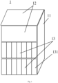
- Fig. 1 is a schematic diagram of a tissue processor according to an embodiment of the present invention.
- the tissue processor 1 may include a body 11, a processing retort 12 and a reagent management device 13.
- the reagent management device 13 may accommodate a plurality of reagent bottles 131.
- the plurality of reagent bottles 131 are filled with different reagents, for example, 100% ethanol, 90% ethanol, 80% ethanol, 75% ethanol, xylene, paraffin, and the like.
- At least one dispensing valve and a plurality of dispensing conduits are also provided in the tissue processor 1.
- the reagent in the reagent bottle 131 flows into the processing retort 12 through the corresponding dispensing valve and dispensing conduit.
- the specimen may be automatically exposed in a sequence of reagents in the processing retort 12 to realize such as fixing, dehydration, clearing, embedding, and the like.
- the sequence of reagents in the processing retort 12 may be eliminated from the tissue processor 1 through the corresponding dispensing conduit or returned to the reagent bottles 131 through the corresponding dispensing conduits in sequence.
- tissue processor 1 Other devices may also be provided in the tissue processor 1, for example, a cassette basket, a protective device, and the like. Since there devices of the tissue processor 1 do not have a substantial impact on understanding the embodiments of the present invention, they are omitted herein and will not be described in detail.
- the reagents dispensed into the processing retort 12 are consumed.
- water molecules in the specimen are replaced by molecules of the reagent, such as the water molecules in the specimen are replaced by ethanol molecules, such that the water molecules in the specimen may flow into the reagent, and the molecules of the reagent may flow into the specimen.
- a concentration of the reagent decreases.
- the reagent may stick to the specimen, causing a drop in the concentration of the reagent. If the concentration of the reagent drops to a certain threshold, it will affect the process effect.
- the operator needs to replace the expired or deteriorated reagent in the reagent bottle.
- the operator takes out the reagent bottle 131 containing the reagent from the reagent management device 13, dumps the expired or deteriorated reagent in the reagent bottle 131, washes the reagent bottle 131, fills the reagent bottle 131 with the fresh reagent, and places the reagent bottle 131 with the fresh reagent back in the reagent management device 13.
- the embodiments of the present invention provide a tissue processor comprising an apparatus for indicating a reagent status in a reagent bottle in the tissue processor.
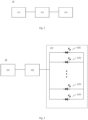
- Fig. 2 is a block diagram illustrating an apparatus for indicating a reagent status in a reagent bottle in a tissue processor according to an embodiment of the present invention.
- the apparatus 10 includes a detector 101, a controller 102, and an indicator 103.
- the detector 101 is configured to detect the reagent status.
- the controller 102 is configured to generate a control signal based on the reagent status.
- the indicator 103 is configured to generate a signal for indicating the reagent status based on the control signal.
- the reagent status may include a normal status, a status requiring an operator's attention, or an expired or deteriorated status.
- the detector 101 may represent different statuses as different digital information, such as different logical codes, and send the digital information to the controller 102.
- the controller 102 may recognize the digital information, generate the corresponding control signal and send the control signal to the indicator 103.
- the indicator 103 may generate a signal for indicating the reagent status based on the control signal.
- the apparatus may intuitively indicate the reagent status for the operator based on the signal generated by the indicator for indicating the reagent status, such that the operator may replace the reagent timely and accurately, avoiding reagent replacement error.
- the detector 101 may detect a density value of the reagent using a densitometer.
- the controller 102 may determine the reagent status based on the detected density value.
- the detector 101 may further calculate the first number of specimens that the reagent has processed and acquire the second number of specimens that the reagent can handle, and determine the reagent status based on the first number and the second number. For example, for a certain reagent, the number of specimens that this reagent can handle is 3000. When the detector 101 calculates 0 to 1500 specimens, the reagent status may be determined as the normal status; when the detector 101 calculates 1501 ⁇ 2500 specimens, the reagent status may be determined as the status requiring the operator's attention; and when the detector 101 calculates 2501 specimens, the reagent status may be determined as the expired or deteriorated status. It should be understood that the above examples are only intended to enable those skilled in the art to understand the embodiments of the present invention, and are not intended to limit the scope of the present invention.
- the controller 102 may be arranged to a central controller of the tissue processor 1, or independently at a proper position of the tissue processor 1, for example an inner wall of the body 11.
- the indicator 103 is disposed to be corresponding to the reagent bottle 131.
- the arrangement of the detector 101, controller 102 and indicator 103 relates to their corresponding implementation.
- the signal for indicating the reagent status is a visual signal.
- the indicator 103 includes a plurality of display modules 1031.
- Each display module 1031 includes at least one signal lamp.
- each display module 1031 includes one signal lamp.
- the signal lamp may be a Light Emitting Diode (LED). It should be understood by those skilled in the art that, based on an implementation scenario, each display module 1031 also may include two signal lamps, three signal lamps, or the like, which is not limited by the embodiments of the present invention.
- the reagent status may be visually and intuitively indicated for the operator, such that the operator may replace the reagent timely and accurately, and the reagent replacement error is avoided.
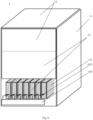
- the plurality of display modules 1031 are in one-to-one correspondence with the plurality of reagent bottles 131. As illustrated in Fig. 4 , one display module 1031 corresponds to one reagent bottle 131. The plurality of display modules 1031 serves as backlight modules of the plurality of reagent bottles 131, respectively. The signal lamp in each display module 1031 may emit different light based on the control signal to illuminate the corresponding reagent bottle 131.
- At least one signal lamp is configured to emit predetermined light in accordance with the control signal.
- the predetermined light includes one of light with a first predetermined color, light with a second predetermined color, and light that flashes at a predetermined flashing frequency.
- the control signal may be a current signal or a voltage signal.
- the signal lamp emits light with different colors based on different current signals or different voltage signals.
- the control signal also may be a pulse current signal or a pulse voltage signal. The signal lamp emits light that flashes at the predetermined flashing frequency based on the pulse current signal or the pulse voltage signal.
- the controller 102 is configured to generate a first control signal when the reagent status is within a threshold range.
- the at least signal lamp is configured to emit the light with the first predetermined color based on the first control signal. For example, a difference of decreasing in the concentration of ethanol is within (0.1% to 1%], the reagent statues may be determined as the normal statues.
- the controller 102 generates the first control signal.
- the at least one signal lamp emits green or blue light based on the first control signal.
- the controller 102 is configured to generate a second control signal when the reagent status is within a forewarning threshold range.
- the at least signal lamp is configured to emit the light with the second predetermined color based on the second control signal. For example, the difference of decreasing in the concentration of ethanol is within (1% ⁇ 5%], the reagent statues may be determined as the statues requiring the operator's attention.
- the controller 102 generates the second control signal.
- the at least one signal lamp emits orange or red light based on the second control signal.
- the controller 102 is configured to generate a third control signal when the reagent status is within an alarm threshold range.
- the at least signal lamp is configured to emit the light that flashes at the predetermined flashing frequency based on the third control signal. For example, the difference of decreasing in the concentration of ethanol is 5% or less, the reagent statues may be determined as the expired or deteriorated statues.
- the controller 102 generates the third control signal.
- the at least one signal lamp emits the light that flashes at the predetermined flashing frequency based on the third control signal.
- the apparatus 10 may also include a touch control screen 104.
- the touch control screen 104 is configured to synchronously display the signal for indicating the reagent status.
- the touch control screen 104 may be placed over the processing retort 12 to facilitate the operator.
- the signal 2 generated by the indicator 103 is synchronized as the signal 2' displayed on the touch control panel 104.
- the touch control screen 104 may also display other operations of the tissue processor 1 and corresponding statuses, etc., which are not described in detail herein.
- the signal for indicating the reagent status may be an audible signal.
- the indicator 103 includes a plurality of buzzers 1032.
- the plurality of buzzers 1032 are in one-to-one correspondence with a plurality of reagent bottles 131.
- the plurality of buzzers 1032 are respectively disposed in front of the plurality of reagent bottles 131.
- Each buzzer 1302 are configured to emit a sound signal with a preset frequency based on the control signal.
- the reagent status may be acoustically and intuitively indicated for the operator, such that the operator may replace the reagent timely and accurately, and the reagent replacement error is avoided.
- the controller 102 is configured to generate a first control signal when the reagent status is within a threshold range.
- the buzzer 1302 is configured to emit a sound signal with a first preset frequency based on the first control signal. For example, a difference of decreasing in the concentration of ethanol is within (0.1% to 1%], the reagent statues may be determined as the normal statues.
- the controller 102 generates the first control signal.
- the buzzer 1302 emits a normal "drip" sound based on the first control signal.
- the controller 102 is configured to generate a second control signal when the reagent status is within a forewarning threshold range.
- the buzzer 1302 is configured to emit a sound signal with a second preset frequency based on the second control signal.
- the second preset frequency is greater than the first preset frequency. For example, the difference of decreasing in the concentration of ethanol is within (1% ⁇ 5%], the reagent statues may be determined as the statues requiring the operator's attention, and the controller 102 generates the second control signal.
- the buzzer 1302 emits a slightly higher frequency "drip" sound based on the second control signal.
- the controller 102 is configured to generate a third control signal when the reagent status is within an alarm threshold range.
- the buzzer 1302 is configured to emit a sound signal with a third preset frequency based on the third control signal.
- the third preset frequency is greater than the second preset frequency. For example, the difference of decreasing in the concentration of ethanol is 5% or less, the reagent statues may be determined as the expired or deteriorated statues.
- the controller 102 generates the third control signal.
- the buzzer 1302 emits a higher frequency "drip" sound based on the third control signal.
- embodiments of the present invention provide a method for indicating a reagent status in a reagent bottle in a tissue processor.
- Fig. 8 is a flow chart showing a method for indicating a reagent status in a reagent bottle in a tissue processor according to an embodiment of the present invention. As illustrated in Fig. 8 , the method includes following operations.
- the reagent status is detected.
- a control signal is generated based on the reagent status.
- a signal for indicating the reagent status is generated based on the control signal.
- the signal for indicating the reagent status is generated based on the control signal as follows. Predetermined light is emitted based on the control signal.
- the predetermined light includes one of light with a first predetermined color, light with a second predetermined color, and light that flashes at a predetermined flashing frequency.
- the predetermined light is emitted based on the control signal as follows.
- the reagent status is within a threshold range
- the light with the first predetermined color is emitted.
- the reagent status is within a forewarning threshold range
- the light with the second predetermined color is emitted.
- the reagent status is within an alarm threshold range
- the light that flashes at the predetermined flashing frequency is emitted.
- the signal for indicating the reagent status is generated based on the control signal as follows.
- a sound signal with a preset frequency is emitted based on the control signal.
- the method further includes following operations. It is detected whether the reagent bottle is placed in the tissue processor. A turn-off signal is generated when detecting that the reagent bottle is not placed in the tissue processor. The signal for indicating the reagent status is turned off based on the turn-off signal.
- embodiments of the present invention also provide a tissue processor including the above apparatus 10 for indicating a reagent status in a reagent bottle in a tissue processor.
- tissue processor it may intuitively indicate the reagent status for the operator based on the signal generated by the indicator for indicating the reagent status, such that the operator may replace the reagent timely and accurately, avoiding reagent replacement error.
- the terms “mounted,” “connected,” “coupled,” “fixed” and the like are used broadly, and may be, for example, fixed connections, detachable connections, or integral connections; may also be mechanical or electrical connections; may also be direct connections or indirect connections via intervening structures; may also be inner communications of two elements, which can be understood by those skilled in the art according to specific situations.
- the first characteristic is “on” or “under” the second characteristic refers to the first characteristic and the second characteristic can be direct or via media indirect mountings, connections, and couplings.
- the first characteristic is "on”, “above”, “over” the second characteristic may refer to the first characteristic is right over the second characteristic or is diagonal above the second characteristic, or just refer to the horizontal height of the first characteristic is higher than the horizontal height of the second characteristic.
- the first characteristic is “below” or “under” the second characteristic may refer to the first characteristic is right over the second characteristic or is diagonal under the second characteristic, or just refer to the horizontal height of the first characteristic is lower than the horizontal height of the second characteristic.
Landscapes
- Life Sciences & Earth Sciences (AREA)
- Health & Medical Sciences (AREA)
- Immunology (AREA)
- Chemical & Material Sciences (AREA)
- Analytical Chemistry (AREA)
- Biochemistry (AREA)
- General Health & Medical Sciences (AREA)
- General Physics & Mathematics (AREA)
- Physics & Mathematics (AREA)
- Pathology (AREA)
- Engineering & Computer Science (AREA)
- Quality & Reliability (AREA)
- Biomedical Technology (AREA)
- Molecular Biology (AREA)
- Automatic Analysis And Handling Materials Therefor (AREA)
- User Interface Of Digital Computer (AREA)
Description
- The present disclosure relates to a technical field of tissue processors, and more particularly to a tissue processor comprising an apparatus for indicating a reagent status in a reagent bottle in the tissue processor, and a method for indicating a reagent status in a reagent bottle in the tissue processor.
- A tissue processor is a device for processing (e.g. fixing, dehydration, clearing, embedding, etc.) specimens by automatically exposing the specimens to a sequence of reagents in its processing retort. However, the reagents are consumed in a procedure of processing the specimens.
-
US 5,389,339 A shows an integral biomolecule preparation device comprising a reagent add assembly and a status display and alarm signal assembly controlled by a computer. Reagent add assembly comprises reagent storage containers having reagent level sensors. An alarm signal assembly comprises CRT or LCD read-out and status or alarm signals or lights for signaling conditions such as reagent levels. - The present disclosure aims to solve at least one of the problems in the related art to at least some extent.
- Accordingly, a first objective of the present disclosure is to provide an apparatus for indicating a reagent status in a reagent bottle in a tissue processor. The apparatus may intuitively indicate the reagent status for an operator, such that the operator may replace the reagent timely and accurately, avoiding reagent replacement error.
- A second objective of the present disclosure is to provide a method for indicating a reagent status in a reagent bottle in a tissue processor.
- A third objective of the present disclosure is to provide a tissue processor.
- In order to realize the above objectives, the present invention provides a tissue processor comprising an apparatus for indicating a reagent status in a reagent bottle in a tissue processor. The apparatus includes: a detector, a controller, and an indicator. The detector is configured to detect the reagent status. The controller is configured to generate a control signal based on the reagent status. The indicator is configured to generate a signal for indicating the reagent status based on the control signal.
- According to the invention, the indicator includes a plurality of display modules. The plurality of display modules is in one-to-one correspondence with a plurality of reagent bottles in the tissue processor.
- In at least one embodiment, each of the plurality of display modules includes at least one signal lamp. The at least one signal lamp is configured to emit predetermined light based on the control signal.
- In at least one embodiment, the predetermined light includes one of light with a first predetermined color, light with a second predetermined color, and light that flashes at a predetermined flashing frequency.
- In at least one embodiment, when the reagent status is within a threshold range, the controller is configured to generate a first control signal, and the at least signal lamp is configured to emit the light with the first predetermined color based on the first control signal; when the reagent status is within a forewarning threshold range, the controller is configured to generate a second control signal, and the at least signal lamp is configured to emit the light with the second predetermined color based on the second control signal; and when the reagent status is within an alarm threshold range, the controller is configured to generate a third control signal, and the at least signal lamp is configured to emit the light that flashes at the predetermined flashing frequency based on the third control signal.
- According to the invention, the plurality of display modules serves as backlight modules of the plurality of reagent bottles, respectively.
- In at least one embodiment, the indicator includes a plurality of buzzers. The plurality of buzzers is in one-to-one correspondence with a plurality of reagent bottles in the tissue processer. The plurality of buzzers is configured to emit a sound signal with a predetermined frequency based on the control signal.
- In at least one embodiment, the detector is further configured to detect whether the reagent bottle is placed in the tissue processor; the controller is further configured to generate a turn-off signal when detecting that the reagent bottle is not placed in the tissue processor; the indicator is further configured to turn off the signal for indicating the reagent status based on the turn-off signal.
- In at least one embodiment, the apparatus further includes: a touch control screen, configured to synchronously display the signal for indicating the reagent status.
- In order to realize the above objectives, the present invention provides a method for indicating a reagent status in a reagent bottle in the tissue processor according to the invention. The method includes: detecting the reagent status; generating a control signal based on the reagent status; and generating a signal for indicating the reagent status based on the control signal.
- In at least one embodiment, generating the signal for indicating the reagent status based on the control signal, includes: emitting predetermined light based on the control signal.
- In at least one embodiment, the predetermined light includes one of light with a first predetermined color, light with a second predetermined color, and light that flashes at a predetermined flashing frequency.
- In at least one embodiment, emitting the predetermined light based on the control signal, includes: when the reagent status is within a threshold range, emitting the light with the first predetermined color; when the reagent status is within a forewarning threshold range, emitting the light with the second predetermined color; and when the reagent status is within an alarm threshold range, emitting the light that flashes at the flashing predetermined frequency.
- In at least one embodiment, generating the signal for indicating the reagent status based on the control signal, includes: emitting a sound signal with a preset frequency based on the control signal.
- In at least one embodiment, the method further includes: detecting whether the reagent bottle is placed in the tissue processor; generating a turn-off signal when detecting that the reagent bottle is not placed in the tissue processor; turning off the signal for indicating the reagent status based on the turn-off signal.
-
-
Fig. 1 is a front view of a tissue processor according to an embodiment of the present invention. -
Fig. 2 is a block diagram illustrating an apparatus for indicating a reagent status in a reagent bottle in a tissue processor according to an embodiment of the present invention. -
Fig. 3 is a block diagram illustrating an apparatus for indicating a reagent status in a reagent bottle in a tissue processor according to another embodiment of the present invention. -
Fig. 4 is a back view of a tissue processor according to an embodiment of the present invention. -
Fig. 5 is a block diagram illustrating an apparatus for indicating a reagent status in a reagent bottle in a tissue processor according to still another embodiment of the present invention. -
Fig. 6 is a front view of a tissue processor according to another embodiment of the present invention. -
Fig. 7 is a block diagram illustrating an apparatus for indicating a reagent status in a reagent bottle in a tissue processor according to yet still another embodiment of the present invention. -
Fig. 8 is a flow chart showing a method for indicating a reagent status in a reagent bottle in a tissue processor according to an embodiment of the present invention. -
Fig. 9 is a block diagram illustrating a tissue processor according to an embodiment of the present invention. - Reference will be made in detail to embodiments of the present invention. Embodiments of the present invention will be illustrated in drawings, in which the same or similar elements and the elements having same or similar functions are denoted by like reference numerals throughout the descriptions. The embodiments described herein according to drawings are explanatory and illustrative, not construed to limit the present invention.
-
Fig. 1 is a schematic diagram of a tissue processor according to an embodiment of the present invention. As illustrated inFig. 1 , thetissue processor 1 may include abody 11, aprocessing retort 12 and areagent management device 13. Thereagent management device 13 may accommodate a plurality ofreagent bottles 131. The plurality ofreagent bottles 131 are filled with different reagents, for example, 100% ethanol, 90% ethanol, 80% ethanol, 75% ethanol, xylene, paraffin, and the like. At least one dispensing valve and a plurality of dispensing conduits (not illustrated) are also provided in thetissue processor 1. The reagent in thereagent bottle 131 flows into theprocessing retort 12 through the corresponding dispensing valve and dispensing conduit. The specimen may be automatically exposed in a sequence of reagents in theprocessing retort 12 to realize such as fixing, dehydration, clearing, embedding, and the like. The sequence of reagents in theprocessing retort 12 may be eliminated from thetissue processor 1 through the corresponding dispensing conduit or returned to thereagent bottles 131 through the corresponding dispensing conduits in sequence. - Other devices may also be provided in the
tissue processor 1, for example, a cassette basket, a protective device, and the like. Since there devices of thetissue processor 1 do not have a substantial impact on understanding the embodiments of the present invention, they are omitted herein and will not be described in detail. - When the specimen is automatically exposed in the sequence of reagents in the
processing retort 12, the reagents dispensed into theprocessing retort 12 are consumed. For example, in the dehydration, water molecules in the specimen are replaced by molecules of the reagent, such as the water molecules in the specimen are replaced by ethanol molecules, such that the water molecules in the specimen may flow into the reagent, and the molecules of the reagent may flow into the specimen. As a result, a concentration of the reagent decreases. For another example, the reagent may stick to the specimen, causing a drop in the concentration of the reagent. If the concentration of the reagent drops to a certain threshold, it will affect the process effect. Therefore, the operator needs to replace the expired or deteriorated reagent in the reagent bottle. The operator takes out thereagent bottle 131 containing the reagent from thereagent management device 13, dumps the expired or deteriorated reagent in thereagent bottle 131, washes thereagent bottle 131, fills thereagent bottle 131 with the fresh reagent, and places thereagent bottle 131 with the fresh reagent back in thereagent management device 13. - In the above process of replacing the reagent, it is easy to cause an operation error. For example, the operator fails to replace the expired or deteriorated reagent in time, or the operator replace the wrong reagent into the reagent bottle. In order to intuitively indicate the operator to enable the operator to be aware of the reagent status in time, the embodiments of the present invention provide a tissue processor comprising an apparatus for indicating a reagent status in a reagent bottle in the tissue processor.
-
Fig. 2 is a block diagram illustrating an apparatus for indicating a reagent status in a reagent bottle in a tissue processor according to an embodiment of the present invention. As illustrated inFig. 2 , theapparatus 10 includes adetector 101, acontroller 102, and anindicator 103. Thedetector 101 is configured to detect the reagent status. Thecontroller 102 is configured to generate a control signal based on the reagent status. Theindicator 103 is configured to generate a signal for indicating the reagent status based on the control signal. - In an embodiment of the present invention, the reagent status may include a normal status, a status requiring an operator's attention, or an expired or deteriorated status. The
detector 101 may represent different statuses as different digital information, such as different logical codes, and send the digital information to thecontroller 102. Thecontroller 102 may recognize the digital information, generate the corresponding control signal and send the control signal to theindicator 103. Theindicator 103 may generate a signal for indicating the reagent status based on the control signal. - With the apparatus according to the embodiments of the present invention, it may intuitively indicate the reagent status for the operator based on the signal generated by the indicator for indicating the reagent status, such that the operator may replace the reagent timely and accurately, avoiding reagent replacement error.
- In an embodiment of the present invention, the
detector 101 may detect a density value of the reagent using a densitometer. Thecontroller 102 may determine the reagent status based on the detected density value. - In an embodiment of the present invention, the
detector 101 may further calculate the first number of specimens that the reagent has processed and acquire the second number of specimens that the reagent can handle, and determine the reagent status based on the first number and the second number. For example, for a certain reagent, the number of specimens that this reagent can handle is 3000. When thedetector 101 calculates 0 to 1500 specimens, the reagent status may be determined as the normal status; when thedetector 101 calculates 1501~2500 specimens, the reagent status may be determined as the status requiring the operator's attention; and when thedetector 101 calculates 2501 specimens, the reagent status may be determined as the expired or deteriorated status. It should be understood that the above examples are only intended to enable those skilled in the art to understand the embodiments of the present invention, and are not intended to limit the scope of the present invention. - In an embodiment of the present invention, the
controller 102 may be arranged to a central controller of thetissue processor 1, or independently at a proper position of thetissue processor 1, for example an inner wall of thebody 11. - In an embodiment of the present invention, the
indicator 103 is disposed to be corresponding to thereagent bottle 131. - The arrangement of the
detector 101,controller 102 andindicator 103 relates to their corresponding implementation. - The signal for indicating the reagent status is a visual signal. As illustrated in
Fig. 3 , theindicator 103 includes a plurality ofdisplay modules 1031. Eachdisplay module 1031 includes at least one signal lamp. For example, in the embodiment ofFig. 3 , eachdisplay module 1031 includes one signal lamp. The signal lamp may be a Light Emitting Diode (LED). It should be understood by those skilled in the art that, based on an implementation scenario, eachdisplay module 1031 also may include two signal lamps, three signal lamps, or the like, which is not limited by the embodiments of the present invention. - With the above embodiments, the reagent status may be visually and intuitively indicated for the operator, such that the operator may replace the reagent timely and accurately, and the reagent replacement error is avoided.
- The plurality of
display modules 1031 are in one-to-one correspondence with the plurality ofreagent bottles 131. As illustrated inFig. 4 , onedisplay module 1031 corresponds to onereagent bottle 131. The plurality ofdisplay modules 1031 serves as backlight modules of the plurality ofreagent bottles 131, respectively. The signal lamp in eachdisplay module 1031 may emit different light based on the control signal to illuminate thecorresponding reagent bottle 131. - In an embodiment of the present invention, at least one signal lamp is configured to emit predetermined light in accordance with the control signal. The predetermined light includes one of light with a first predetermined color, light with a second predetermined color, and light that flashes at a predetermined flashing frequency. The control signal may be a current signal or a voltage signal. The signal lamp emits light with different colors based on different current signals or different voltage signals. The control signal also may be a pulse current signal or a pulse voltage signal. The signal lamp emits light that flashes at the predetermined flashing frequency based on the pulse current signal or the pulse voltage signal.
- In an embodiment of the present invention, the
controller 102 is configured to generate a first control signal when the reagent status is within a threshold range. The at least signal lamp is configured to emit the light with the first predetermined color based on the first control signal. For example, a difference of decreasing in the concentration of ethanol is within (0.1% to 1%], the reagent statues may be determined as the normal statues. Thecontroller 102 generates the first control signal. The at least one signal lamp emits green or blue light based on the first control signal. - In an embodiment of the present invention, the
controller 102 is configured to generate a second control signal when the reagent status is within a forewarning threshold range. The at least signal lamp is configured to emit the light with the second predetermined color based on the second control signal. For example, the difference of decreasing in the concentration of ethanol is within (1%~5%], the reagent statues may be determined as the statues requiring the operator's attention. Thecontroller 102 generates the second control signal. The at least one signal lamp emits orange or red light based on the second control signal. - In an embodiment of the present invention, the
controller 102 is configured to generate a third control signal when the reagent status is within an alarm threshold range. The at least signal lamp is configured to emit the light that flashes at the predetermined flashing frequency based on the third control signal. For example, the difference of decreasing in the concentration of ethanol is 5% or less, the reagent statues may be determined as the expired or deteriorated statues. Thecontroller 102 generates the third control signal. The at least one signal lamp emits the light that flashes at the predetermined flashing frequency based on the third control signal. - It should be understood that the above numerical examples are only intended to enable those skilled in the art to understand the embodiments of the present invention, and are not intended to limit the scope of the present invention.
- In an embodiment of the present invention, as illustrated in
Fig. 5 , theapparatus 10 may also include atouch control screen 104. Thetouch control screen 104 is configured to synchronously display the signal for indicating the reagent status. As illustrated inFig. 6 , thetouch control screen 104 may be placed over theprocessing retort 12 to facilitate the operator. As illustrated inFig. 6 , thesignal 2 generated by theindicator 103 is synchronized as the signal 2' displayed on thetouch control panel 104. It should also be understood that thetouch control screen 104 may also display other operations of thetissue processor 1 and corresponding statuses, etc., which are not described in detail herein. - In an embodiment of the present invention, the signal for indicating the reagent status may be an audible signal. For example, as illustrated in
Fig. 7 , theindicator 103 includes a plurality ofbuzzers 1032. The plurality ofbuzzers 1032 are in one-to-one correspondence with a plurality ofreagent bottles 131. The plurality ofbuzzers 1032 are respectively disposed in front of the plurality ofreagent bottles 131. Each buzzer 1302 are configured to emit a sound signal with a preset frequency based on the control signal. - With the above embodiments, the reagent status may be acoustically and intuitively indicated for the operator, such that the operator may replace the reagent timely and accurately, and the reagent replacement error is avoided.
- In an embodiment of the present invention, the
controller 102 is configured to generate a first control signal when the reagent status is within a threshold range. The buzzer 1302 is configured to emit a sound signal with a first preset frequency based on the first control signal. For example, a difference of decreasing in the concentration of ethanol is within (0.1% to 1%], the reagent statues may be determined as the normal statues. Thecontroller 102 generates the first control signal. The buzzer 1302 emits a normal "drip" sound based on the first control signal. - In an embodiment of the present invention, the
controller 102 is configured to generate a second control signal when the reagent status is within a forewarning threshold range. The buzzer 1302 is configured to emit a sound signal with a second preset frequency based on the second control signal. The second preset frequency is greater than the first preset frequency. For example, the difference of decreasing in the concentration of ethanol is within (1%~5%], the reagent statues may be determined as the statues requiring the operator's attention, and thecontroller 102 generates the second control signal. The buzzer 1302 emits a slightly higher frequency "drip" sound based on the second control signal. - In an embodiment of the present invention, the
controller 102 is configured to generate a third control signal when the reagent status is within an alarm threshold range. The buzzer 1302 is configured to emit a sound signal with a third preset frequency based on the third control signal. The third preset frequency is greater than the second preset frequency. For example, the difference of decreasing in the concentration of ethanol is 5% or less, the reagent statues may be determined as the expired or deteriorated statues. Thecontroller 102 generates the third control signal. The buzzer 1302 emits a higher frequency "drip" sound based on the third control signal. - In order to realize the above embodiments, embodiments of the present invention provide a method for indicating a reagent status in a reagent bottle in a tissue processor.
-
Fig. 8 is a flow chart showing a method for indicating a reagent status in a reagent bottle in a tissue processor according to an embodiment of the present invention. As illustrated inFig. 8 , the method includes following operations. - At block 801, the reagent status is detected.
- At
block 802, a control signal is generated based on the reagent status. - At
block 803, a signal for indicating the reagent status is generated based on the control signal. - With the method according to the embodiments of the present invention, it may intuitively indicate the reagent status for the operator based on the signal for indicating the reagent status, such that the operator may replace the reagent timely and accurately, avoiding reagent replacement error.
- In an embodiment of the present invention, the signal for indicating the reagent status is generated based on the control signal as follows. Predetermined light is emitted based on the control signal.
- In an embodiment of the present invention, the predetermined light includes one of light with a first predetermined color, light with a second predetermined color, and light that flashes at a predetermined flashing frequency.
- In an embodiment of the present invention, the predetermined light is emitted based on the control signal as follows. When the reagent status is within a threshold range, the light with the first predetermined color is emitted. When the reagent status is within a forewarning threshold range, the light with the second predetermined color is emitted. When the reagent status is within an alarm threshold range, the light that flashes at the predetermined flashing frequency is emitted.
- In an embodiment of the present invention, the signal for indicating the reagent status is generated based on the control signal as follows. A sound signal with a preset frequency is emitted based on the control signal.
- In an embodiment of the present invention, the method further includes following operations. It is detected whether the reagent bottle is placed in the tissue processor. A turn-off signal is generated when detecting that the reagent bottle is not placed in the tissue processor. The signal for indicating the reagent status is turned off based on the turn-off signal.
- With respect to specific implementation of the above method, reference can be made to the above-described embodiment of the apparatus, which will not be elaborated herein.
- In addition, as illustrated in
Fig. 9 , embodiments of the present invention also provide a tissue processor including theabove apparatus 10 for indicating a reagent status in a reagent bottle in a tissue processor. - With the tissue processor according to the embodiments of the present invention, it may intuitively indicate the reagent status for the operator based on the signal generated by the indicator for indicating the reagent status, such that the operator may replace the reagent timely and accurately, avoiding reagent replacement error.
- It is to be understood that, in the description, terms such as "first" and "second" are used herein for purposes of description and are not intended to indicate or imply relative importance or significance. Thus, the feature defined with "first" and "second" may comprise one or more this feature. In the description of the present invention, "a plurality of" means two or more than two, unless specified otherwise.
- In the present utility model, unless specified or limited otherwise, the terms "mounted," "connected," "coupled," "fixed" and the like are used broadly, and may be, for example, fixed connections, detachable connections, or integral connections; may also be mechanical or electrical connections; may also be direct connections or indirect connections via intervening structures; may also be inner communications of two elements, which can be understood by those skilled in the art according to specific situations.
- In the present invention, unless specified or limited otherwise, the first characteristic is "on" or "under" the second characteristic refers to the first characteristic and the second characteristic can be direct or via media indirect mountings, connections, and couplings. And, the first characteristic is "on", "above", "over" the second characteristic may refer to the first characteristic is right over the second characteristic or is diagonal above the second characteristic, or just refer to the horizontal height of the first characteristic is higher than the horizontal height of the second characteristic. The first characteristic is "below" or "under" the second characteristic may refer to the first characteristic is right over the second characteristic or is diagonal under the second characteristic, or just refer to the horizontal height of the first characteristic is lower than the horizontal height of the second characteristic.
- Reference throughout this specification to "an embodiment," "some embodiments," "one embodiment", "another example," "an example," "a specific example," or "some examples," means that a particular feature, structure, material, or characteristic described in connection with the embodiment or example is included in at least one embodiment or example of the present utility model. Thus, the appearances of the phrases such as "in some embodiments," "in one embodiment", "in an embodiment", "in another example," "in an example," "in a specific example," or "in some examples," in various places throughout this specification are not necessarily referring to the same embodiment or example of the present utility model. Furthermore, the particular features, structures, materials, or characteristics may be combined in any suitable manner in one or more embodiments or examples.
Claims (13)
- A tissue processor (1), comprising an apparatus for indicating a reagent status in a reagent bottle (131) in the tissue processor (1), comprising:a detector (101), configured to detect the reagent status;a controller (102), configured to generate a control signal based on the reagent status; andan indicator (103), configured to generate a signal for indicating the reagent status based on the control signal,characterised in thatthe indicator (103) comprises a plurality of display modules (1031), the plurality of display modules (1031) being in one-to-one correspondence with a plurality of reagent bottles (131) in the tissue processor (1),wherein the plurality of display modules (1031) serves as backlight modules of the plurality of reagent bottles (131), respectively.
- The tissue processor (1) of claim 1, wherein each of the plurality of display modules (1031) comprises at least one signal lamp, and the at least one signal lamp is configured to emit predetermined light based on the control signal.
- The tissue processor (1) of claim 2, wherein the predetermined light comprises one of light with a first predetermined color, light with a second predetermined color, and light that flashes at a predetermined flashing frequency.
- The tissue processor (1) of claim 3,when the reagent status is within a threshold range, the controller (102) is configured to generate a first control signal, and the at least signal lamp is configured to emit the light with the first predetermined color based on the first control signal;when the reagent status is within a forewarning threshold range, the controller (102) is configured to generate a second control signal, and the at least signal lamp is configured to emit the light with the second predetermined color based on the second control signal; andwhen the reagent status is within an alarm threshold range, the controller (102) is configured to generate a third control signal, and the at least signal lamp is configured to emit the light that flashes at the predetermined flashing frequency based on the third control signal.
- The tissue processor (1) of any one of the preceding claims, wherein the indicator (103) comprises a plurality of buzzers, the plurality of buzzers being in one-to-one correspondence with a plurality of reagent bottles (131) in the tissue processor, and the plurality of buzzers being configured to emit a sound signal with a preset frequency based on the control signal.
- The tissue processor (1) of any one of the preceding claims, whereinthe detector (101) is further configured to detect whether the reagent bottle (131) is placed in the tissue processor (1);the controller (102) is further configured to generate a turn-off signal when detecting that the reagent bottle (131) is not placed in the tissue processor (1);the indicator (103) is further configured to turn off the signal for indicating the reagent status based on the turn-off signal.
- The tissue processor (1) of any one of the preceding claims, further comprising:
a touch control screen (104), configured to synchronously display the signal for indicating the reagent status. - A method for indicating a reagent status in a reagent bottle (131) in a tissue processor (1) of any one of the preceding claims, comprising:detecting the reagent status;generating a control signal based on the reagent status; andgenerating a signal for indicating the reagent status based on the control signal.
- The method of claim 8, wherein, generating the signal for indicating the reagent status based on the control signal, comprising:
emitting predetermined light based on the control signal. - The method of claim 9, wherein the predetermined light comprises one of light with a first predetermined color, light with a second predetermined color, and light that flashes at a predetermined flashing frequency.
- The method of claim 10, wherein, emitting the predetermined light based on the control signal, comprises:when the reagent status is within a threshold range, emitting the light with the first predetermined color;when the reagent status is within a forewarning threshold range, emitting the light with the second predetermined color; andwhen the reagent status is within an alarm threshold range, emitting the light that flashes at the predetermined flashing frequency.
- The method of any one of claims 8 to 11, wherein, generating the signal for indicating the reagent status based on the control signal, comprises:
emitting a sound signal with a preset frequency based on the control signal. - The method of any one of claims 8 to 12, further comprising:detecting whether the reagent bottle (131) is placed in the tissue processor (1);generating a turn-off signal when detecting that the reagent bottle (131) is not placed in the tissue processor (1);turning off the signal for indicating the reagent status based on the turn-off signal.
Applications Claiming Priority (2)
| Application Number | Priority Date | Filing Date | Title |
|---|---|---|---|
| CN201811300958.7A CN111141564A (en) | 2018-11-02 | 2018-11-02 | Device, method and tissue processor for indicating the state of a solvent |
| PCT/EP2019/079937 WO2020089441A1 (en) | 2018-11-02 | 2019-10-31 | Apparatus and method for indicating reagent status and tissue processor |
Publications (2)
| Publication Number | Publication Date |
|---|---|
| EP3837554A1 EP3837554A1 (en) | 2021-06-23 |
| EP3837554B1 true EP3837554B1 (en) | 2023-05-10 |
Family
ID=68536799
Family Applications (1)
| Application Number | Title | Priority Date | Filing Date |
|---|---|---|---|
| EP19801773.3A Active EP3837554B1 (en) | 2018-11-02 | 2019-10-31 | Apparatus and method for indicating reagent status and tissue processor |
Country Status (5)
| Country | Link |
|---|---|
| US (1) | US12360129B2 (en) |
| EP (1) | EP3837554B1 (en) |
| JP (1) | JP7434297B2 (en) |
| CN (1) | CN111141564A (en) |
| WO (1) | WO2020089441A1 (en) |
Families Citing this family (2)
| Publication number | Priority date | Publication date | Assignee | Title |
|---|---|---|---|---|
| CN116134302B (en) * | 2020-07-31 | 2025-09-12 | 莱卡生物系统努斯洛赫有限责任公司 | Method and apparatus for monitoring concentration of reagent, electronic device, and computer-readable storage medium |
| CN114264537A (en) * | 2021-12-21 | 2022-04-01 | 达科为(深圳)医疗设备有限公司 | Dehydrator, control method and system thereof, electronic device, and readable storage medium |
Citations (1)
| Publication number | Priority date | Publication date | Assignee | Title |
|---|---|---|---|---|
| EP3153865A1 (en) * | 2014-06-03 | 2017-04-12 | Hitachi High-Technologies Corporation | Automatic analyzer |
Family Cites Families (14)
| Publication number | Priority date | Publication date | Assignee | Title |
|---|---|---|---|---|
| AU639575B2 (en) * | 1990-05-01 | 1993-07-29 | Enprotech Corporation | Integral biomolecule preparation device |
| JP2003028769A (en) | 2001-07-12 | 2003-01-29 | Chiyoda Manufacturing Co Ltd | Tissue processing equipment |
| JP2008070259A (en) * | 2006-09-14 | 2008-03-27 | Olympus Corp | Observation device |
| JP5203141B2 (en) * | 2008-10-31 | 2013-06-05 | シスメックス株式会社 | Sample analyzer, method for displaying reagent information in sample analyzer, and computer program |
| DE102008054071B4 (en) * | 2008-10-31 | 2014-02-20 | Leica Biosystems Nussloch Gmbh | Method of operating a tissue processor and tissue processor |
| JP6031229B2 (en) | 2011-12-28 | 2016-11-24 | シスメックス株式会社 | Sample measuring apparatus and sample measuring method |
| JP6434407B2 (en) | 2013-07-09 | 2018-12-05 | 株式会社日立ハイテクノロジーズ | Automatic analyzer |
| DE102016111991A1 (en) * | 2016-06-30 | 2018-01-04 | Leica Biosystems Nussloch Gmbh | Treatment device for treating histological or cytological specimens |
| WO2018051672A1 (en) * | 2016-09-16 | 2018-03-22 | 株式会社 日立ハイテクノロジーズ | Automated analyzer, automated analysis system, and method for displaying reagent list |
| CN206114669U (en) * | 2016-09-29 | 2017-04-19 | 吉林工程技术师范学院 | Immune colloidal gold reagent plate for detecting tripolycyanamide |
| JP6937116B2 (en) | 2016-12-15 | 2021-09-22 | シスメックス株式会社 | Pretreatment device and pretreatment method |
| US11428700B2 (en) * | 2017-08-22 | 2022-08-30 | Leica Biosystems Melbourne Pty Ltd | Histological tissue specimen processing |
| CN207163796U (en) * | 2017-09-04 | 2018-03-30 | 合肥普立通科技有限公司 | A kind of fluid level condition suggestion device |
| EP3626652B1 (en) * | 2018-09-20 | 2025-09-17 | F. Hoffmann-La Roche AG | Consumable management system for laboratories |
-
2018
- 2018-11-02 CN CN201811300958.7A patent/CN111141564A/en active Pending
-
2019
- 2019-10-31 EP EP19801773.3A patent/EP3837554B1/en active Active
- 2019-10-31 WO PCT/EP2019/079937 patent/WO2020089441A1/en not_active Ceased
- 2019-10-31 US US17/279,223 patent/US12360129B2/en active Active
- 2019-10-31 JP JP2021516691A patent/JP7434297B2/en active Active
Patent Citations (1)
| Publication number | Priority date | Publication date | Assignee | Title |
|---|---|---|---|---|
| EP3153865A1 (en) * | 2014-06-03 | 2017-04-12 | Hitachi High-Technologies Corporation | Automatic analyzer |
Also Published As
| Publication number | Publication date |
|---|---|
| JP2022503802A (en) | 2022-01-12 |
| CN111141564A (en) | 2020-05-12 |
| JP7434297B2 (en) | 2024-02-20 |
| EP3837554A1 (en) | 2021-06-23 |
| US12360129B2 (en) | 2025-07-15 |
| US20220034924A1 (en) | 2022-02-03 |
| WO2020089441A1 (en) | 2020-05-07 |
Similar Documents
| Publication | Publication Date | Title |
|---|---|---|
| CN103743343B (en) | Data center IT (information technology) machine cabinet volume detection method and system | |
| US12360129B2 (en) | Apparatus and method for indicating reagent status and tissue processor | |
| JP3220452U (en) | Intelligent indicator lamp device | |
| CN207181428U (en) | A kind of sample analyser | |
| JP5690543B2 (en) | Specimen automation equipment, automatic analysis equipment and system | |
| CN106068454B (en) | Systems and methods for component end-of-life detection and signaling in dissolved oxygen sensors | |
| JP2022503802A5 (en) | ||
| CN206114064U (en) | Water level flow rate measuring device | |
| US20200182797A1 (en) | Method for notifying sample analyzer status and sample analysis system | |
| CN118270356A (en) | Medicine bottle infrared detection method, medicine storage device and storage medium | |
| CN201020754Y (en) | Chain saw | |
| CN110594594A (en) | Intelligent pipeline blockage tester | |
| CN102928759A (en) | LED (Light-Emitting Diode) projector light source detection method and LED projector | |
| CN210180617U (en) | A valve leak detection device | |
| CN101738539A (en) | Electronic electric energy meter and detection method of signal indicator lights thereof | |
| JP2020044577A (en) | Container with indicator | |
| CN215417487U (en) | Automatic screen touch device | |
| CN219545698U (en) | A storage tank for glycerol | |
| CN214202609U (en) | A laboratory waste liquid storage safety monitoring device | |
| CN214017290U (en) | Intelligent discharging machine for kitchen seasoning liquid | |
| JP2663738B2 (en) | Level meter | |
| CN224094403U (en) | An LED navigation light status monitoring system | |
| JPS6334407B2 (en) | ||
| CN221854553U (en) | A 96-well plate with sample loading indicator | |
| CN219827179U (en) | Flow testing device special for centrifugal pump of in-vitro diagnostic device |
Legal Events
| Date | Code | Title | Description |
|---|---|---|---|
| STAA | Information on the status of an ep patent application or granted ep patent |
Free format text: STATUS: UNKNOWN |
|
| STAA | Information on the status of an ep patent application or granted ep patent |
Free format text: STATUS: THE INTERNATIONAL PUBLICATION HAS BEEN MADE |
|
| PUAI | Public reference made under article 153(3) epc to a published international application that has entered the european phase |
Free format text: ORIGINAL CODE: 0009012 |
|
| STAA | Information on the status of an ep patent application or granted ep patent |
Free format text: STATUS: REQUEST FOR EXAMINATION WAS MADE |
|
| 17P | Request for examination filed |
Effective date: 20210318 |
|
| AK | Designated contracting states |
Kind code of ref document: A1 Designated state(s): AL AT BE BG CH CY CZ DE DK EE ES FI FR GB GR HR HU IE IS IT LI LT LU LV MC MK MT NL NO PL PT RO RS SE SI SK SM TR |
|
| DAV | Request for validation of the european patent (deleted) | ||
| DAX | Request for extension of the european patent (deleted) | ||
| STAA | Information on the status of an ep patent application or granted ep patent |
Free format text: STATUS: EXAMINATION IS IN PROGRESS |
|
| 17Q | First examination report despatched |
Effective date: 20221017 |
|
| REG | Reference to a national code |
Ref country code: DE Ref legal event code: R079 Ipc: G01N0001310000 Ref country code: DE Ref legal event code: R079 Ref document number: 602019028846 Country of ref document: DE Free format text: PREVIOUS MAIN CLASS: G01N0035000000 Ipc: G01N0001310000 |
|
| GRAP | Despatch of communication of intention to grant a patent |
Free format text: ORIGINAL CODE: EPIDOSNIGR1 |
|
| STAA | Information on the status of an ep patent application or granted ep patent |
Free format text: STATUS: GRANT OF PATENT IS INTENDED |
|
| RIC1 | Information provided on ipc code assigned before grant |
Ipc: G01N 35/00 20060101ALI20230113BHEP Ipc: G01N 1/31 20060101AFI20230113BHEP |
|
| INTG | Intention to grant announced |
Effective date: 20230201 |
|
| GRAS | Grant fee paid |
Free format text: ORIGINAL CODE: EPIDOSNIGR3 |
|
| GRAA | (expected) grant |
Free format text: ORIGINAL CODE: 0009210 |
|
| STAA | Information on the status of an ep patent application or granted ep patent |
Free format text: STATUS: THE PATENT HAS BEEN GRANTED |
|
| AK | Designated contracting states |
Kind code of ref document: B1 Designated state(s): AL AT BE BG CH CY CZ DE DK EE ES FI FR GB GR HR HU IE IS IT LI LT LU LV MC MK MT NL NO PL PT RO RS SE SI SK SM TR |
|
| REG | Reference to a national code |
Ref country code: GB Ref legal event code: FG4D |
|
| REG | Reference to a national code |
Ref country code: AT Ref legal event code: REF Ref document number: 1567138 Country of ref document: AT Kind code of ref document: T Effective date: 20230515 Ref country code: CH Ref legal event code: EP |
|
| REG | Reference to a national code |
Ref country code: DE Ref legal event code: R096 Ref document number: 602019028846 Country of ref document: DE |
|
| REG | Reference to a national code |
Ref country code: IE Ref legal event code: FG4D |
|
| P01 | Opt-out of the competence of the unified patent court (upc) registered |
Effective date: 20230525 |
|
| REG | Reference to a national code |
Ref country code: LT Ref legal event code: MG9D |
|
| REG | Reference to a national code |
Ref country code: NL Ref legal event code: MP Effective date: 20230510 |
|
| REG | Reference to a national code |
Ref country code: AT Ref legal event code: MK05 Ref document number: 1567138 Country of ref document: AT Kind code of ref document: T Effective date: 20230510 |
|
| PG25 | Lapsed in a contracting state [announced via postgrant information from national office to epo] |
Ref country code: SE Free format text: LAPSE BECAUSE OF FAILURE TO SUBMIT A TRANSLATION OF THE DESCRIPTION OR TO PAY THE FEE WITHIN THE PRESCRIBED TIME-LIMIT Effective date: 20230510 Ref country code: PT Free format text: LAPSE BECAUSE OF FAILURE TO SUBMIT A TRANSLATION OF THE DESCRIPTION OR TO PAY THE FEE WITHIN THE PRESCRIBED TIME-LIMIT Effective date: 20230911 Ref country code: NO Free format text: LAPSE BECAUSE OF FAILURE TO SUBMIT A TRANSLATION OF THE DESCRIPTION OR TO PAY THE FEE WITHIN THE PRESCRIBED TIME-LIMIT Effective date: 20230810 Ref country code: NL Free format text: LAPSE BECAUSE OF FAILURE TO SUBMIT A TRANSLATION OF THE DESCRIPTION OR TO PAY THE FEE WITHIN THE PRESCRIBED TIME-LIMIT Effective date: 20230510 Ref country code: ES Free format text: LAPSE BECAUSE OF FAILURE TO SUBMIT A TRANSLATION OF THE DESCRIPTION OR TO PAY THE FEE WITHIN THE PRESCRIBED TIME-LIMIT Effective date: 20230510 Ref country code: AT Free format text: LAPSE BECAUSE OF FAILURE TO SUBMIT A TRANSLATION OF THE DESCRIPTION OR TO PAY THE FEE WITHIN THE PRESCRIBED TIME-LIMIT Effective date: 20230510 |
|
| PG25 | Lapsed in a contracting state [announced via postgrant information from national office to epo] |
Ref country code: RS Free format text: LAPSE BECAUSE OF FAILURE TO SUBMIT A TRANSLATION OF THE DESCRIPTION OR TO PAY THE FEE WITHIN THE PRESCRIBED TIME-LIMIT Effective date: 20230510 Ref country code: PL Free format text: LAPSE BECAUSE OF FAILURE TO SUBMIT A TRANSLATION OF THE DESCRIPTION OR TO PAY THE FEE WITHIN THE PRESCRIBED TIME-LIMIT Effective date: 20230510 Ref country code: LV Free format text: LAPSE BECAUSE OF FAILURE TO SUBMIT A TRANSLATION OF THE DESCRIPTION OR TO PAY THE FEE WITHIN THE PRESCRIBED TIME-LIMIT Effective date: 20230510 Ref country code: LT Free format text: LAPSE BECAUSE OF FAILURE TO SUBMIT A TRANSLATION OF THE DESCRIPTION OR TO PAY THE FEE WITHIN THE PRESCRIBED TIME-LIMIT Effective date: 20230510 Ref country code: IS Free format text: LAPSE BECAUSE OF FAILURE TO SUBMIT A TRANSLATION OF THE DESCRIPTION OR TO PAY THE FEE WITHIN THE PRESCRIBED TIME-LIMIT Effective date: 20230910 Ref country code: HR Free format text: LAPSE BECAUSE OF FAILURE TO SUBMIT A TRANSLATION OF THE DESCRIPTION OR TO PAY THE FEE WITHIN THE PRESCRIBED TIME-LIMIT Effective date: 20230510 Ref country code: GR Free format text: LAPSE BECAUSE OF FAILURE TO SUBMIT A TRANSLATION OF THE DESCRIPTION OR TO PAY THE FEE WITHIN THE PRESCRIBED TIME-LIMIT Effective date: 20230811 |
|
| PG25 | Lapsed in a contracting state [announced via postgrant information from national office to epo] |
Ref country code: FI Free format text: LAPSE BECAUSE OF FAILURE TO SUBMIT A TRANSLATION OF THE DESCRIPTION OR TO PAY THE FEE WITHIN THE PRESCRIBED TIME-LIMIT Effective date: 20230510 |
|
| PG25 | Lapsed in a contracting state [announced via postgrant information from national office to epo] |
Ref country code: SK Free format text: LAPSE BECAUSE OF FAILURE TO SUBMIT A TRANSLATION OF THE DESCRIPTION OR TO PAY THE FEE WITHIN THE PRESCRIBED TIME-LIMIT Effective date: 20230510 |
|
| PG25 | Lapsed in a contracting state [announced via postgrant information from national office to epo] |
Ref country code: SM Free format text: LAPSE BECAUSE OF FAILURE TO SUBMIT A TRANSLATION OF THE DESCRIPTION OR TO PAY THE FEE WITHIN THE PRESCRIBED TIME-LIMIT Effective date: 20230510 Ref country code: SK Free format text: LAPSE BECAUSE OF FAILURE TO SUBMIT A TRANSLATION OF THE DESCRIPTION OR TO PAY THE FEE WITHIN THE PRESCRIBED TIME-LIMIT Effective date: 20230510 Ref country code: RO Free format text: LAPSE BECAUSE OF FAILURE TO SUBMIT A TRANSLATION OF THE DESCRIPTION OR TO PAY THE FEE WITHIN THE PRESCRIBED TIME-LIMIT Effective date: 20230510 Ref country code: EE Free format text: LAPSE BECAUSE OF FAILURE TO SUBMIT A TRANSLATION OF THE DESCRIPTION OR TO PAY THE FEE WITHIN THE PRESCRIBED TIME-LIMIT Effective date: 20230510 Ref country code: DK Free format text: LAPSE BECAUSE OF FAILURE TO SUBMIT A TRANSLATION OF THE DESCRIPTION OR TO PAY THE FEE WITHIN THE PRESCRIBED TIME-LIMIT Effective date: 20230510 Ref country code: CZ Free format text: LAPSE BECAUSE OF FAILURE TO SUBMIT A TRANSLATION OF THE DESCRIPTION OR TO PAY THE FEE WITHIN THE PRESCRIBED TIME-LIMIT Effective date: 20230510 |
|
| REG | Reference to a national code |
Ref country code: DE Ref legal event code: R097 Ref document number: 602019028846 Country of ref document: DE |
|
| PLBE | No opposition filed within time limit |
Free format text: ORIGINAL CODE: 0009261 |
|
| STAA | Information on the status of an ep patent application or granted ep patent |
Free format text: STATUS: NO OPPOSITION FILED WITHIN TIME LIMIT |
|
| 26N | No opposition filed |
Effective date: 20240213 |
|
| PG25 | Lapsed in a contracting state [announced via postgrant information from national office to epo] |
Ref country code: SI Free format text: LAPSE BECAUSE OF FAILURE TO SUBMIT A TRANSLATION OF THE DESCRIPTION OR TO PAY THE FEE WITHIN THE PRESCRIBED TIME-LIMIT Effective date: 20230510 |
|
| PG25 | Lapsed in a contracting state [announced via postgrant information from national office to epo] |
Ref country code: SI Free format text: LAPSE BECAUSE OF FAILURE TO SUBMIT A TRANSLATION OF THE DESCRIPTION OR TO PAY THE FEE WITHIN THE PRESCRIBED TIME-LIMIT Effective date: 20230510 Ref country code: IT Free format text: LAPSE BECAUSE OF FAILURE TO SUBMIT A TRANSLATION OF THE DESCRIPTION OR TO PAY THE FEE WITHIN THE PRESCRIBED TIME-LIMIT Effective date: 20230510 Ref country code: MC Free format text: LAPSE BECAUSE OF FAILURE TO SUBMIT A TRANSLATION OF THE DESCRIPTION OR TO PAY THE FEE WITHIN THE PRESCRIBED TIME-LIMIT Effective date: 20230510 |
|
| REG | Reference to a national code |
Ref country code: CH Ref legal event code: PL |
|
| REG | Reference to a national code |
Ref country code: BE Ref legal event code: MM Effective date: 20231031 |
|
| PG25 | Lapsed in a contracting state [announced via postgrant information from national office to epo] |
Ref country code: LU Free format text: LAPSE BECAUSE OF NON-PAYMENT OF DUE FEES Effective date: 20231031 |
|
| PG25 | Lapsed in a contracting state [announced via postgrant information from national office to epo] |
Ref country code: LU Free format text: LAPSE BECAUSE OF NON-PAYMENT OF DUE FEES Effective date: 20231031 |
|
| PG25 | Lapsed in a contracting state [announced via postgrant information from national office to epo] |
Ref country code: CH Free format text: LAPSE BECAUSE OF NON-PAYMENT OF DUE FEES Effective date: 20231031 |
|
| PG25 | Lapsed in a contracting state [announced via postgrant information from national office to epo] |
Ref country code: CH Free format text: LAPSE BECAUSE OF NON-PAYMENT OF DUE FEES Effective date: 20231031 |
|
| PG25 | Lapsed in a contracting state [announced via postgrant information from national office to epo] |
Ref country code: BE Free format text: LAPSE BECAUSE OF NON-PAYMENT OF DUE FEES Effective date: 20231031 |
|
| PG25 | Lapsed in a contracting state [announced via postgrant information from national office to epo] |
Ref country code: IE Free format text: LAPSE BECAUSE OF NON-PAYMENT OF DUE FEES Effective date: 20231031 |
|
| PG25 | Lapsed in a contracting state [announced via postgrant information from national office to epo] |
Ref country code: IE Free format text: LAPSE BECAUSE OF NON-PAYMENT OF DUE FEES Effective date: 20231031 |
|
| PG25 | Lapsed in a contracting state [announced via postgrant information from national office to epo] |
Ref country code: BG Free format text: LAPSE BECAUSE OF FAILURE TO SUBMIT A TRANSLATION OF THE DESCRIPTION OR TO PAY THE FEE WITHIN THE PRESCRIBED TIME-LIMIT Effective date: 20230510 |
|
| PG25 | Lapsed in a contracting state [announced via postgrant information from national office to epo] |
Ref country code: BG Free format text: LAPSE BECAUSE OF FAILURE TO SUBMIT A TRANSLATION OF THE DESCRIPTION OR TO PAY THE FEE WITHIN THE PRESCRIBED TIME-LIMIT Effective date: 20230510 |
|
| PG25 | Lapsed in a contracting state [announced via postgrant information from national office to epo] |
Ref country code: CY Free format text: LAPSE BECAUSE OF FAILURE TO SUBMIT A TRANSLATION OF THE DESCRIPTION OR TO PAY THE FEE WITHIN THE PRESCRIBED TIME-LIMIT; INVALID AB INITIO Effective date: 20191031 |
|
| PG25 | Lapsed in a contracting state [announced via postgrant information from national office to epo] |
Ref country code: HU Free format text: LAPSE BECAUSE OF FAILURE TO SUBMIT A TRANSLATION OF THE DESCRIPTION OR TO PAY THE FEE WITHIN THE PRESCRIBED TIME-LIMIT; INVALID AB INITIO Effective date: 20191031 |
|
| PG25 | Lapsed in a contracting state [announced via postgrant information from national office to epo] |
Ref country code: TR Free format text: LAPSE BECAUSE OF FAILURE TO SUBMIT A TRANSLATION OF THE DESCRIPTION OR TO PAY THE FEE WITHIN THE PRESCRIBED TIME-LIMIT Effective date: 20230510 |
|
| PGFP | Annual fee paid to national office [announced via postgrant information from national office to epo] |
Ref country code: DE Payment date: 20251028 Year of fee payment: 7 |
|
| PGFP | Annual fee paid to national office [announced via postgrant information from national office to epo] |
Ref country code: GB Payment date: 20251023 Year of fee payment: 7 |
|
| PGFP | Annual fee paid to national office [announced via postgrant information from national office to epo] |
Ref country code: FR Payment date: 20251027 Year of fee payment: 7 |