EP3837542B1 - Verfahren und vorrichtung zur inspektion eines zustands einer auf einer spritze aufgesetzten kanüle - Google Patents
Verfahren und vorrichtung zur inspektion eines zustands einer auf einer spritze aufgesetzten kanüle Download PDFInfo
- Publication number
- EP3837542B1 EP3837542B1 EP19753301.1A EP19753301A EP3837542B1 EP 3837542 B1 EP3837542 B1 EP 3837542B1 EP 19753301 A EP19753301 A EP 19753301A EP 3837542 B1 EP3837542 B1 EP 3837542B1
- Authority
- EP
- European Patent Office
- Prior art keywords
- magnetic field
- cannula
- syringe
- measured
- longitudinal axis
- Prior art date
- Legal status (The legal status is an assumption and is not a legal conclusion. Google has not performed a legal analysis and makes no representation as to the accuracy of the status listed.)
- Active
Links
Images

Classifications
-
- G—PHYSICS
- G01—MEASURING; TESTING
- G01N—INVESTIGATING OR ANALYSING MATERIALS BY DETERMINING THEIR CHEMICAL OR PHYSICAL PROPERTIES
- G01N27/00—Investigating or analysing materials by the use of electric, electrochemical, or magnetic means
- G01N27/72—Investigating or analysing materials by the use of electric, electrochemical, or magnetic means by investigating magnetic variables
- G01N27/82—Investigating or analysing materials by the use of electric, electrochemical, or magnetic means by investigating magnetic variables for investigating the presence of flaws
- G01N27/83—Investigating or analysing materials by the use of electric, electrochemical, or magnetic means by investigating magnetic variables for investigating the presence of flaws by investigating stray magnetic fields
- G01N27/85—Investigating or analysing materials by the use of electric, electrochemical, or magnetic means by investigating magnetic variables for investigating the presence of flaws by investigating stray magnetic fields using magnetographic methods
-
- G—PHYSICS
- G01—MEASURING; TESTING
- G01R—MEASURING ELECTRIC VARIABLES; MEASURING MAGNETIC VARIABLES
- G01R33/00—Arrangements or instruments for measuring magnetic variables
- G01R33/02—Measuring direction or magnitude of magnetic fields or magnetic flux
- G01R33/10—Plotting field distribution ; Measuring field distribution
-
- A—HUMAN NECESSITIES
- A61—MEDICAL OR VETERINARY SCIENCE; HYGIENE
- A61M—DEVICES FOR INTRODUCING MEDIA INTO, OR ONTO, THE BODY; DEVICES FOR TRANSDUCING BODY MEDIA OR FOR TAKING MEDIA FROM THE BODY; DEVICES FOR PRODUCING OR ENDING SLEEP OR STUPOR
- A61M5/00—Devices for bringing media into the body in a subcutaneous, intra-vascular or intramuscular way; Accessories therefor, e.g. filling or cleaning devices, arm-rests
- A61M5/50—Devices for bringing media into the body in a subcutaneous, intra-vascular or intramuscular way; Accessories therefor, e.g. filling or cleaning devices, arm-rests having means for preventing re-use, or for indicating if defective, used, tampered with or unsterile
- A61M5/5086—Devices for bringing media into the body in a subcutaneous, intra-vascular or intramuscular way; Accessories therefor, e.g. filling or cleaning devices, arm-rests having means for preventing re-use, or for indicating if defective, used, tampered with or unsterile for indicating if defective, used, tampered with or unsterile
-
- G—PHYSICS
- G01—MEASURING; TESTING
- G01N—INVESTIGATING OR ANALYSING MATERIALS BY DETERMINING THEIR CHEMICAL OR PHYSICAL PROPERTIES
- G01N27/00—Investigating or analysing materials by the use of electric, electrochemical, or magnetic means
- G01N27/72—Investigating or analysing materials by the use of electric, electrochemical, or magnetic means by investigating magnetic variables
- G01N27/82—Investigating or analysing materials by the use of electric, electrochemical, or magnetic means by investigating magnetic variables for investigating the presence of flaws
- G01N27/83—Investigating or analysing materials by the use of electric, electrochemical, or magnetic means by investigating magnetic variables for investigating the presence of flaws by investigating stray magnetic fields
- G01N27/87—Investigating or analysing materials by the use of electric, electrochemical, or magnetic means by investigating magnetic variables for investigating the presence of flaws by investigating stray magnetic fields using probes
-
- A—HUMAN NECESSITIES
- A61—MEDICAL OR VETERINARY SCIENCE; HYGIENE
- A61M—DEVICES FOR INTRODUCING MEDIA INTO, OR ONTO, THE BODY; DEVICES FOR TRANSDUCING BODY MEDIA OR FOR TAKING MEDIA FROM THE BODY; DEVICES FOR PRODUCING OR ENDING SLEEP OR STUPOR
- A61M5/00—Devices for bringing media into the body in a subcutaneous, intra-vascular or intramuscular way; Accessories therefor, e.g. filling or cleaning devices, arm-rests
- A61M5/178—Syringes
- A61M5/31—Details
- A61M5/32—Needles; Details of needles pertaining to their connection with syringe or hub; Accessories for bringing the needle into, or holding the needle on, the body; Devices for protection of needles
-
- G—PHYSICS
- G01—MEASURING; TESTING
- G01N—INVESTIGATING OR ANALYSING MATERIALS BY DETERMINING THEIR CHEMICAL OR PHYSICAL PROPERTIES
- G01N27/00—Investigating or analysing materials by the use of electric, electrochemical, or magnetic means
- G01N27/72—Investigating or analysing materials by the use of electric, electrochemical, or magnetic means by investigating magnetic variables
- G01N27/82—Investigating or analysing materials by the use of electric, electrochemical, or magnetic means by investigating magnetic variables for investigating the presence of flaws
-
- G—PHYSICS
- G01—MEASURING; TESTING
- G01R—MEASURING ELECTRIC VARIABLES; MEASURING MAGNETIC VARIABLES
- G01R33/00—Arrangements or instruments for measuring magnetic variables
- G01R33/02—Measuring direction or magnitude of magnetic fields or magnetic flux
-
- A—HUMAN NECESSITIES
- A61—MEDICAL OR VETERINARY SCIENCE; HYGIENE
- A61M—DEVICES FOR INTRODUCING MEDIA INTO, OR ONTO, THE BODY; DEVICES FOR TRANSDUCING BODY MEDIA OR FOR TAKING MEDIA FROM THE BODY; DEVICES FOR PRODUCING OR ENDING SLEEP OR STUPOR
- A61M5/00—Devices for bringing media into the body in a subcutaneous, intra-vascular or intramuscular way; Accessories therefor, e.g. filling or cleaning devices, arm-rests
- A61M5/14—Infusion devices, e.g. infusing by gravity; Blood infusion; Accessories therefor
- A61M5/158—Needles for infusions; Accessories therefor, e.g. for inserting infusion needles, or for holding them on the body
- A61M2005/1588—Needles for infusions; Accessories therefor, e.g. for inserting infusion needles, or for holding them on the body having means for monitoring, controlling or visual inspection, e.g. for patency check, avoiding extravasation
-
- A—HUMAN NECESSITIES
- A61—MEDICAL OR VETERINARY SCIENCE; HYGIENE
- A61M—DEVICES FOR INTRODUCING MEDIA INTO, OR ONTO, THE BODY; DEVICES FOR TRANSDUCING BODY MEDIA OR FOR TAKING MEDIA FROM THE BODY; DEVICES FOR PRODUCING OR ENDING SLEEP OR STUPOR
- A61M2205/00—General characteristics of the apparatus
- A61M2205/02—General characteristics of the apparatus characterised by a particular materials
- A61M2205/0272—Electro-active or magneto-active materials
-
- A—HUMAN NECESSITIES
- A61—MEDICAL OR VETERINARY SCIENCE; HYGIENE
- A61M—DEVICES FOR INTRODUCING MEDIA INTO, OR ONTO, THE BODY; DEVICES FOR TRANSDUCING BODY MEDIA OR FOR TAKING MEDIA FROM THE BODY; DEVICES FOR PRODUCING OR ENDING SLEEP OR STUPOR
- A61M2205/00—General characteristics of the apparatus
- A61M2205/33—Controlling, regulating or measuring
- A61M2205/3317—Electromagnetic, inductive or dielectric measuring means
-
- A—HUMAN NECESSITIES
- A61—MEDICAL OR VETERINARY SCIENCE; HYGIENE
- A61M—DEVICES FOR INTRODUCING MEDIA INTO, OR ONTO, THE BODY; DEVICES FOR TRANSDUCING BODY MEDIA OR FOR TAKING MEDIA FROM THE BODY; DEVICES FOR PRODUCING OR ENDING SLEEP OR STUPOR
- A61M2205/00—General characteristics of the apparatus
- A61M2205/60—General characteristics of the apparatus with identification means
- A61M2205/6054—Magnetic identification systems
-
- A—HUMAN NECESSITIES
- A61—MEDICAL OR VETERINARY SCIENCE; HYGIENE
- A61M—DEVICES FOR INTRODUCING MEDIA INTO, OR ONTO, THE BODY; DEVICES FOR TRANSDUCING BODY MEDIA OR FOR TAKING MEDIA FROM THE BODY; DEVICES FOR PRODUCING OR ENDING SLEEP OR STUPOR
- A61M2205/00—General characteristics of the apparatus
- A61M2205/70—General characteristics of the apparatus with testing or calibration facilities
-
- A—HUMAN NECESSITIES
- A61—MEDICAL OR VETERINARY SCIENCE; HYGIENE
- A61M—DEVICES FOR INTRODUCING MEDIA INTO, OR ONTO, THE BODY; DEVICES FOR TRANSDUCING BODY MEDIA OR FOR TAKING MEDIA FROM THE BODY; DEVICES FOR PRODUCING OR ENDING SLEEP OR STUPOR
- A61M2209/00—Ancillary equipment
- A61M2209/02—Equipment for testing the apparatus
-
- A—HUMAN NECESSITIES
- A61—MEDICAL OR VETERINARY SCIENCE; HYGIENE
- A61M—DEVICES FOR INTRODUCING MEDIA INTO, OR ONTO, THE BODY; DEVICES FOR TRANSDUCING BODY MEDIA OR FOR TAKING MEDIA FROM THE BODY; DEVICES FOR PRODUCING OR ENDING SLEEP OR STUPOR
- A61M5/00—Devices for bringing media into the body in a subcutaneous, intra-vascular or intramuscular way; Accessories therefor, e.g. filling or cleaning devices, arm-rests
- A61M5/178—Syringes
- A61M5/31—Details
- A61M5/32—Needles; Details of needles pertaining to their connection with syringe or hub; Accessories for bringing the needle into, or holding the needle on, the body; Devices for protection of needles
- A61M5/3202—Devices for protection of the needle before use, e.g. caps
Definitions
- the present invention relates to methods for inspecting a condition, in particular for detecting defects, of a cannula (or syringe needle) placed on a syringe and devices for carrying out such methods.
- the cannula or needle underneath can bend or be compressed, pierce through the protective cap or even break. This means that the cannula not only poses a danger to the user, but can also lose its sterility.
- different methods are used to detect such damage. For example, classic image processing is used to detect the position of the protective cap. However, this process sorts out a relatively high proportion of good syringes (high “false rejection rate”). The currently most reliable method is based on X-rays every syringe and on the automatic analysis of the X-ray images taken.
- EP 2 763 722 A2 relates to a system for determining the position of an element, the system comprising a sensor arrangement and a movable element with a built-in magnet which is movable relative to the sensor arrangement to generate a spatial magnetic field.
- the sensor arrangement has one or more sensors, each of which can measure a magnetic field along three axes.
- a processor determines a position of the movable element relative to a given position based on the magnetic field measured by the sensor arrangement.
- US 2012/0307972 A1 describes an inspection device and a method for electromagnetically checking the cannula alignment in a cannula protective cap attached to a syringe.
- the inspection device includes an electromagnetic imager with an emitter and a detector and an image analyzer.
- US 2013/0242082 A1 discloses a system for attaching a needle guard to a syringe, the system comprising an inspection camera positioned near the syringe axis and configured to visually capture information related to the positioning of the needle guard relative to the syringe.
- DE 198 06 971 C1 describes a method for non-contact monitoring at the prescribed location needle protection cap placed on the cannula of a medical syringe and a device for carrying out the procedure.
- a high voltage is applied to the cannula on the one hand and to a counter electrode surrounding the needle protective cap on the other hand, and the current flowing in one of the electrical supply lines to the cannula or to the counter electrode is monitored, whereby if a predetermined current value is exceeded, the syringe subjected to the test is marked as faulty.
- DE 10 2007 040 488 A1 relates to an X-ray device for examining syringe caps having a cannula, with an X-ray source, an X-ray detector and a holder that holds the syringe cap in the beam path at an examination site.
- This object is achieved according to the invention by the testing device specified in claim 9.
- a method for inspecting a condition, in particular for detecting certain defects, of a cannula placed on a syringe, which is located in a cannula protective cap includes measuring a magnetic field, in particular a magnetic field distribution, in an area surrounding the cannula, and determining a deformation of the magnetic field, in particular a field line course, compared to the case of a straight cannula.
- one or more magnetic field sensors in particular an induction sensor, a fluxgate magnetometer, a Hall sensor, a magnetoresistive sensor, such as an AMR (anisotropic sensor), are used to measure the magnetic field, in particular the magnetic field distribution magnetoresistive), CMR (colossal magnetoresistance), GMR (giant magnetoresistance) or TMR (tunnel magnetoresistance) sensor.
- AMR anisotropic sensor
- the one or more magnetic field sensors are designed as one-, two- or three-axis magnetic field sensors in order to measure the magnetic field, in particular the magnetic field distribution, in one, two or three dimensions.
- the cannula in order to measure the magnetic field, in particular the magnetic field distribution, is moved relative to the one or more magnetic field sensors, the syringe in particular being rotated about its longitudinal axis and/or being moved along its longitudinal axis, or the one or more magnetic field sensors are moved parallel to the longitudinal axis of the syringe.
- one or more motors such as servo or stepper motors, are used to rotate and/or move the syringe longitudinally, with a gear being used so that the rotational frequency of the one or more motors is a multiple or a fraction is the rotation frequency of the syringe. This prevents magnetic fields generated by the one or more motors from disturbing the magnetic field to be measured in the area around the cannula or the magnetic field distribution to be measured.
- the magnetic field is generated, at least in part, by the earth's magnetic field, by a magnetic field formed by an arrangement with one or more permanent magnets, or by a magnetic field formed by an arrangement with one or more electromagnets, such as a Helmholtz coil , wherein the arrangement in particular also has one or more iron cores.
- magnetic shielding is used to suppress magnetic interference fields.
- the method includes comparing the measured magnetic field, in particular the measured magnetic field distribution, for the cannula with the measured magnetic field, in particular the measured magnetic field distribution, for a reference syringe with an attached reference cannula, which is located in a cannula protective cap, which has a target state, and determining the state of the cannula placed on the syringe based on the comparison.
- determining the state of the cannula placed on the syringe is based on comparing an amplitude and/or phase position of the measured magnetic field for the reference cannula with an amplitude and/or phase position of the measured magnetic field for the cannula.
- determining the state of the cannula placed on the syringe is based on comparing an amplitude and/or phase position of the measured magnetic field at two different locations, which is measured, for example, with two magnetic field sensors arranged offset from one another.
- the method includes transforming a measured time course of the magnetic field, in particular the magnetic field distribution, from the time domain to the frequency domain.
- the method includes determining a frequency component of the magnetic field, in particular the magnetic field distribution, at a rotation frequency of the syringe, in particular also at twice the rotation frequency of the syringe, for example by means of a discrete Fourier transformation (DFT).
- DFT discrete Fourier transformation
- the state of the cannula is at least one of straight, bent, bent, compressed, chipped/broken, coaxial to the longitudinal axis of the syringe, oblique to the longitudinal axis of the syringe, eccentric to the longitudinal axis of the syringe.
- a device for inspecting a condition of a cannula placed on a syringe, which is located in a cannula protective cap comprises one or more magnetic field sensors, in particular an induction sensor, a fluxgate magnetometer, a Hall sensor, a magnetoresistive sensor , such as an AMR (anisotropic magnetoresistive), CMR (colossal magnetoresistance), GMR (giant magnetoresistance) or TMR (tunnel magnetoresistance) sensor, for example Measuring a magnetic field, in particular a magnetic field distribution, in an area around the cannula.
- AMR anisotropic magnetoresistive
- CMR colossal magnetoresistance
- GMR giant magnetoresistance
- TMR tunnel magnetoresistance
- the device further comprises a comparator unit, the comparator unit for comparing the measured magnetic field, in particular the measured magnetic field distribution, for the cannula with the measured magnetic field, in particular the measured magnetic field distribution, for a reference syringe with an attached reference cannula, which is located in a Cannula protective cap is located, which has a target state, and wherein the comparator unit is designed to determine the state of the cannula placed on the syringe based on the comparison.
- the one or more magnetic field sensors are designed as one-, two- or three-axis magnetic field sensors in order to measure the magnetic field, in particular the magnetic field distribution, in one, two or three dimensions.
- the device further comprises a device for moving the cannula relative to the one or more magnetic field sensors, in particular for rotating the syringe about its longitudinal axis and/or for moving the syringe along its longitudinal axis, or for moving the one or more Magnetic field sensors parallel to the longitudinal axis of the syringe.
- the device further comprises one or more motors, such as servo or stepper motors, for rotating and/or for longitudinally moving the syringe, with a gear being used so that the rotational frequency of the one or more motors is a multiple or a fraction is the rotation frequency of the syringe.
- one or more motors such as servo or stepper motors, for rotating and/or for longitudinally moving the syringe, with a gear being used so that the rotational frequency of the one or more motors is a multiple or a fraction is the rotation frequency of the syringe.
- the device further comprises an arrangement with one or more permanent magnets and/or an arrangement with one or more electromagnets, such as a Helmholtz coil, for generating a magnetic field, the arrangement in particular also having one or more iron cores.
- the device further comprises a magnetic shield for suppressing magnetic interference fields.
- the comparator unit is designed to carry out a comparison of an amplitude and/or phase position of the measured magnetic field for the reference cannula with an amplitude and/or phase position of the measured magnetic field for the cannula, and from this the state of the on the to determine the cannula attached to the syringe.
- the device further comprises a unit for carrying out a transformation of a measured time course of the magnetic field, in particular the magnetic field distribution, from the time domain to the frequency domain.
- the device further comprises an output, in particular for providing an output signal, which is designed to indicate the state of the cannula as at least one of straight, bent, kinked, compressed, chipped/broken, coaxial to the longitudinal axis of the syringe, oblique to The longitudinal axis of the syringe must be specified eccentrically to the longitudinal axis of the syringe.
- a plurality of magnetic field sensors are arranged vertically one above the other along an axis, in particular equidistantly spaced, the axis being arranged laterally parallel to the longitudinal axis of the syringe to be inspected.
- the device comprises a Helmholtz coil consisting of two coaxially arranged coils, the coil axis of which is arranged horizontally in order to generate the magnetic field in the horizontal direction, with the syringe being arranged between the two coils for the inspection.
- the cannula or syringe needle is placed on the syringe or attached to it, e.g. glued, and then a protective cap is attached to the cannula.
- the cannula must penetrate the material of the protective cap. Accordingly, this process takes place with a certain amount of force, so that the cannula can, for example, be bent, kinked, compressed or (break) off.
- Fig. 1 shows an X-ray image of a syringe 1 with an optically non-transparent protective cap 3 attached, under which there is a bent cannula 2, as recorded in a method according to the prior art.
- the present invention utilizes the effect that ferromagnetic materials influence an external magnetic field in their surroundings. Ferromagnetic materials tend to attract magnetic fields into themselves.
- the field lines of an external magnetic field ends on the surface of the ferromagnetic body and runs inside it.
- the presence of a steel syringe needle causes a local change in the course of the magnetic field lines. An intact, ie straight, needle will cause a different change in the magnetic field lines than a needle that has a bend, for example.
- Fig. 2 schematically illustrates an example of the field line F of the earth's magnetic field in the vicinity of a bent syringe needle or cannula 2.
- the earth's magnetic field tilts towards the earth to different degrees. That's how it points Fig. 2
- the earth's magnetic field shown has an inclination of 64° downwards corresponding to the 47th parallel.
- the magnetic field lines F are bundled by the steel syringe needle 2 and the field lines further out are deflected towards the syringe needle 2.
- This deformation of the field line profile, compared to the case where the syringe needle 2 is straight, can be determined by measuring the magnetic field, in particular the magnetic field distribution, in the area surrounding the cannula 2. Based on the measurement of the magnetic field at one or more points, for example on or along the measuring section S, conclusions can then be drawn about the condition of the cannula 2, ie whether it has a specific defect such as a kink.
- one or more magnetic field sensors such as an induction sensor, a fluxgate magnetometer, a Hall sensor, a magnetoresistive sensor, such as an AMR (anisotropic magnetoresistive), CMR, can be used.
- AMR anisotropic magnetoresistive
- CMR CMR
- These magnetic field sensors can be designed as one-, two- or three-axis magnetic field sensors in order to measure the magnetic field or the magnetic field distribution in one, two or three dimensions.
- the cannula 2 can be moved relative to one or more magnetic field sensors, or conversely one or more magnetic field sensors can be moved relative to the cannula 2, for example vertically along the measuring section S, so that the magnetic field or the magnetic field distribution over the entire length of the cannula 2 can be determined.
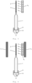
- FIG. 3 A side view of an embodiment variant of a device according to the invention for inspecting syringe needles is shown schematically.
- the syringe 1 is clamped in a syringe holder 5, which is arranged on a rotation/rotation device 6, by means of which the syringe 1 can be rotated about its longitudinal axis a. Due to the rotation, the cannula 2 periodically changes the earth's magnetic field in the area around the cannula 2.
- the earth's magnetic field is determined with the help of the magnetic field sensor arrangement 4 A , which consists of five Magnetic field sensors 4 1 , ..., 4 5 , which are arranged vertically one above the other parallel to the longitudinal axis of the syringe a, are measured.
- the magnetic field sensor arrangement 4 A which consists of five Magnetic field sensors 4 1 , ..., 4 5 , which are arranged vertically one above the other parallel to the longitudinal axis of the syringe a, are measured.
- a single magnetic field sensor could also be used, which is moved up or down along the measuring section S.
- the time course of the measured magnetic field is then transformed into the frequency range. This can be done for individual frequencies, for example using discrete Fourier transformation.
- the distribution of the magnetic field along the cannula 2 will therefore have a greater maximum at the rotation frequency with the bent tip than with a straight cannula 2.
- the bend will also result in a different phase position of the magnetic field compared to the situation with a straight one Cannula 2.
- phase position can also be: Difference in the phase of the magnetic field at two spaced magnetic field sensors 4 1...5 (eg two adjacent magnetic field sensors 4 i & 4 i-1 of the magnetic field sensor arrangement 4 A ) can be used.
- a gear can be used, for example, so that the syringe 1 rotates many times faster or slower than the servo motor. For example, if the speed of the servo motor is three times as high as the rotation speed of the syringe (i.e. gear ratio 3:1), the magnetic field to be measured at the rotation frequency of the syringe 1 is hardly disturbed by the interference field, which is caused by the servo motor at three times the rotation frequency of the syringe Syringe 1 is created.
- magnetic shielding can also be used to suppress magnetic interference fields.
- a magnetic field formed by an arrangement with one or more permanent magnets, or by an arrangement with one or more electromagnets, such as a Helmholtz coil, can also be used, the arrangement in particular also one or can have several iron cores. This can, for example, generate a strong, homogeneous magnetic field.
- FIG. 4 A side view of such an embodiment variant with a Helmholtz coil is shown schematically.
- One coil of the Helmholtz coil pair 7 1 , 7_ is arranged on the left and right of the cannula 2 to be inspected.
- a homogeneous, horizontally oriented magnetic field is formed between the two coils 7 1 , 7 2 , which (as in Fig. 3 ) can be measured with the magnetic field sensor arrangement 4 A.
Landscapes
- Health & Medical Sciences (AREA)
- Physics & Mathematics (AREA)
- General Health & Medical Sciences (AREA)
- Life Sciences & Earth Sciences (AREA)
- Chemical & Material Sciences (AREA)
- General Physics & Mathematics (AREA)
- Hematology (AREA)
- Animal Behavior & Ethology (AREA)
- Veterinary Medicine (AREA)
- Public Health (AREA)
- Heart & Thoracic Surgery (AREA)
- Biomedical Technology (AREA)
- Anesthesiology (AREA)
- Vascular Medicine (AREA)
- Engineering & Computer Science (AREA)
- Pathology (AREA)
- Immunology (AREA)
- Chemical Kinetics & Catalysis (AREA)
- Electrochemistry (AREA)
- Biochemistry (AREA)
- Analytical Chemistry (AREA)
- Condensed Matter Physics & Semiconductors (AREA)
- Infusion, Injection, And Reservoir Apparatuses (AREA)
- Investigating Or Analyzing Materials By The Use Of Magnetic Means (AREA)
Description
- Die vorliegende Erfindung betrifft Verfahren zur Inspektion eines Zustands, insbesondere zur Erkennung von Defekten, einer auf einer Spritze aufgesetzten Kanüle (bzw. Spritzennadel) und Vorrichtungen zur Ausführung solcher Verfahren.
- Bei der Herstellung von medizinischen Spritzen kann es beim Aufsetzten der nicht durchsichtigen Schutzkappe (engl. Needle Shield) dazu kommen, dass sich die darunterliegende Kanüle bzw. Nadel verbiegt oder gestaucht wird, diese durch die Schutzkappe sticht oder sogar bricht. So wird die Kanüle nicht nur eine Gefahr für den Benutzer, sondern kann auch ihre Sterilität verlieren. Heute werden unterschiedliche Methoden zum Erkennen solcher Schäden eingesetzt. So wird etwa die klassische Bildverarbeitung verwendet, um die Stellung der Schutzkappe zu erkennen. Dieses Verfahren sortiert jedoch einen relativ hohen Anteil an guten Spritzen aus (hohe "False Rejection Rate"). Die derzeit wohl zuverlässigste Methode beruht auf dem Röntgen jeder Spritze und auf der automatischen Analyse der aufgenommenen Röntgenbilder. Diese Technologie ist aber ziemlich aufwändig, so muss z.B. der Röntgenbereich gegen aussen abgeschirmt sein, was sehr kostenintensiv ist. Zudem kann das Produkt durch die Röntgenstrahlung belastet werden. Alternativ gibt es die Hochspannungsprüfung. Dabei wird eine unter Hochspannung stehende Elektrode an das Ende mit der Schutzkappe gehalten. Wenn die Kanüle durch die Schutzkappe sticht, ist dies mit der Hochspannungsprüfung erkennbar. Verbogene, gestauchte oder gebrochenen Kanülen, die sich unter einer intakten Schutzkappe befinden, sind jedoch nicht zuverlässig zu erkennen.
- Es besteht daher der Bedarf nach Mitteln, welche eine einfache (und folglich kostengünstige) sowie zuverlässige Erkennung von Defekten an einer auf einer Spritze aufgesetzten Kanüle ermöglichen. Um in Inspektionsmaschinen mit einem hohen Durchsatz von Prüflingen, wie z.B. um 600 Spritzen pro Minute, eingesetzt werden zu können, müssen die Mittel zudem in der Lage sein, die einzelnen Prüflinge sehr rasch mit hoher Zuverlässigkeit prüfen zu können.
-
EP 2 763 722 A2 betrifft ein System zur Bestimmung der Position eines Elements, wobei das System eine Sensoranordnung und ein bewegliches Element mit einem eingebauten Magnet, das relativ zur Sensoranordnung bewegbar ist, um ein räumliches Magnetfeld zu erzeugen, umfasst. Die Sensoranordnung weist einen oder mehrere Sensoren auf, von denen jeder ein Magnetfeld entlang von drei Achsen messen kann. Ein Prozessor bestimmt anhand des von der Sensoranordnung gemessenen Magnetfelds eine Position des beweglichen Elements relativ zu einer gegebenen Position. -
US 2012/0307972 A1 beschreibt eine Inspektionsvorrichtung sowie ein Verfahren zur elektromagnetischen Überprüfung der Kanülenausrichtung in einem an einer Spritze befestigten Kanülenschutzkappe. Die Inspektionsvorrichtung umfasst einen elektromagnetischen Bildgeber mit einem Emitter und einem Detektor sowie einen Bildanalysator. -
US 2013/0242082 A1 offenbart ein System zum Anbringen eines Nadelschutzes an einer Spritze, wobei das System eine Inspektionskamera umfasst, die in der Nähe der Spritzenachse positioniert und dazu konfiguriert ist, visuell Informationen in Bezug auf die Positionierung des Nadelschutzes relativ zu der Spritze zu erfassen. -
DE 198 06 971 C1 beschreibt ein Verfahren zur berührungslosen Überwachung auf vorgeschriebenen Sitz einer auf die Kanüle einer medizinischen Spritze aufgesetzten Nadelschutzkappe sowie eine Vorrichtung zur Durchführung des Verfahrens. Dazu wird an die Kanüle einerseits und an eine die Nadelschutzkappe umgebende Gegenelektrode andererseits eine Hochspannung angelegt und der in einer der elektrischen Zuleitungen zur Kanüle bzw. zur Gegenelektrode fliessende Strom überwacht, wobei bei Überschreitung eines vorgegebenen Stromwertes die der Prüfung unterzogene Spritze als fehlerhaft gekennzeichnet wird. -
DE 10 2007 040 488 A1 betrifft eine Röntgeneinrichtung zur Untersuchung von eine Kanüle aufweisenden Spritzenkappen, mit einer Röntgenstrahlungsquelle, einem Röntgendetektor und einer die Spritzenkappe im Strahlengang an einem Untersuchungsort haltenden Halterung. - Es ist eine Aufgabe der vorliegenden Erfindung ein Verfahren zur raschen, zuverlässigen und kostengünstigen Inspektion eines Zustands, insbesondere zur Erkennung von Defekten, einer auf einer Spritze aufgesetzten Kanüle bereitzustellen. Diese Aufgabe wird erfindungsgemäss durch das in Anspruch 1 festgelegte Prüfverfahren erfüllt.
- Es ist zudem eine Aufgabe der vorliegenden Erfindung eine entsprechende Vorrichtung zur raschen, zuverlässigen und kostengünstigen Inspektion eines Zustands, insbesondere zur Erkennung von Defekten, einer auf einer Spritze aufgesetzten Kanüle vorzuschlagen. Diese Aufgabe wird erfindungsgemäss durch die in Anspruch 9 festgelegte Prüfvorrichtung gelöst.
- Spezifische erfindungsgemässe Ausführungsvarianten werden in den abhängigen Ansprüchen angegeben.
- Ein erfindungsgemässes Verfahren zur Inspektion eines Zustands, insbesondere zum Erkennen von bestimmten Defekten, einer auf einer Spritze aufgesetzten Kanüle, welche sich in einer Kanülenschutzkappe befindet, umfasst ein Messen eines magnetischen Feldes, insbesondere einer magnetischen Feldverteilung, in einer Umgebung der Kanüle, und ein Bestimmen einer Verformung des magnetischen Feldes, insbesondere eines Feldlinienverlaufs, im Vergleich zum Fall einer geraden Kanüle.
- In einer Ausführungsvariante des Verfahrens werden zum Messen des magnetischen Feldes, insbesondere der magnetischen Feldverteilung, ein oder mehrere Magnetfeldsensoren, insbesondere ein Induktionssensor, ein Fluxgate-Magnetometer, ein Hall-Sensor, ein magnetoresistiver Sensor, wie z.B. ein AMR- (engl. "anisotrope magnetoresistive"), CMR- (engl. "colossal magnetoresistance "), GMR- (engl. "giant magnetoresistance") oder TMR- (engl. "tunnel magnetoresistance") Sensor, eingesetzt.
- In einer weiteren Ausführungsvariante des Verfahrens sind der eine oder die mehreren Magnetfeldsensoren als ein-, zwei- oder drei-achsige Magnetfeldsensoren ausgeführt, um das magnetische Feld, insbesondere die magnetische Feldverteilung, ein-, zwei- oder drei-dimensional auszumessen.
- In einer weiteren Ausführungsvariante des Verfahrens wird zum Messen des magnetischen Feldes, insbesondere der magnetischen Feldverteilung, die Kanüle relativ zu dem einen oder den mehreren Magnetfeldsensoren bewegt, wobei die Spritze insbesondere um ihre Längsachse rotiert und/oder entlang ihrer Längsachse bewegt wird, oder der eine oder die mehreren Magnetfeldsensoren parallel zur Längsachse der Spritze bewegt werden.
- In einer weiteren Ausführungsvariante des Verfahrens werden ein oder mehrere Motoren, wie z.B. Servo- oder Schrittmotoren, zum Rotieren und/oder zum Längsbewegen der Spritze eingesetzt, wobei ein Getriebe eingesetzt wird, sodass die Drehfrequenz des einen oder der mehreren Motoren ein Vielfaches oder ein Bruchteil der Rotationsfrequenz der Spritze ist. Dadurch wird verhindert, dass Magnetfelder, welche von dem einen oder den mehreren Motoren erzeugt werden, das in der Umgebung der Kanüle zu messende magnetische Feld, bzw. die zu messende magnetische Feldverteilung, stören.
- In einer weiteren Ausführungsvariante des Verfahrens wird das magnetische Feld, mindestens zum Teil durch das Erdmagnetfeld, durch eine Anordnung mit einem oder mehreren Permanentmagneten gebildetes Magnetfeld, oder durch eine Anordnung mit einem oder mehreren Elektromagneten, wie z.B. einer Helmholtz-Spule, gebildetes Magnetfeld, erzeugt, wobei die Anordnung insbesondere auch einen oder mehrere Eisenkerne aufweist.
- In einer weiteren Ausführungsvariante des Verfahrens wird eine magnetische Abschirmung zur Unterdrückung von magnetischen Störfeldern eingesetzt.
- In einer weiteren Ausführungsvariante umfasst das Verfahren ein Vergleichen des gemessenen magnetischen Feldes, insbesondere der gemessenen magnetischen Feldverteilung, für die Kanüle mit dem gemessenen magnetischen Feld, insbesondere der gemessenen magnetischen Feldverteilung, für eine Referenzspritze mit einer aufgesetzten Referenzkanüle, welche sich in einer Kanülenschutzkappe befindet, welche einen Sollzustand aufweist, und ein Bestimmen des Zustands der auf der Spritze aufgesetzten Kanüle basierend auf dem Vergleichen.
- In einer weiteren Ausführungsvariante des Verfahrens basiert das Bestimmen des Zustands der auf der Spritze aufgesetzten Kanüle auf einem Vergleichen einer Amplitude und/oder Phasenlage des gemessenen magnetischen Feldes für die Referenzkanüle mit einer Amplitude und/oder Phasenlage des gemessenen magnetischen Feldes für die Kanüle.
- In einer weiteren Ausführungsvariante des Verfahrens basiert das Bestimmen des Zustands der auf der Spritze aufgesetzten Kanüle auf einem Vergleichen einer Amplitude und/oder Phasenlage des gemessenen magnetischen Feldes an zwei unterschiedlichen Orten, welches z.B. mit zwei zueinander versetzt angeordneten Magnetfeldsensoren gemessen wird.
- In einer weiteren Ausführungsvariante umfasst das Verfahren ein Transformieren eines gemessenen zeitlichen Verlaufs des magnetischen Feldes, insbesondere der magnetischen Feldverteilung, vom Zeitbereich in den Frequenzbereich.
- In einer weiteren Ausführungsvariante umfasst das Verfahren ein Bestimmen einer Frequenzkomponente des magnetischen Feldes, insbesondere der magnetischen Feldverteilung, bei einer Rotationsfrequenz der Spritze, insbesondere auch bei der doppelten Rotationsfrequenz der Spritze, z.B. mittels einer diskreten Fouriertransformation (DFT).
- In einer weiteren Ausführungsvariante des Verfahrens ist der Zustand der Kanüle mindestens eines von gerade, verbogen, geknickt, gestaucht, ab-/gebrochen, koaxial zur Spritzenlängsachse, schräg zur Spritzenlängsachse, exzentrisch zur Spritzenlängsachse.
- Gemäss einem weiteren Aspekt der vorliegenden Erfindung umfasst eine Vorrichtung zur Inspektion eines Zustands einer auf einer Spritze aufgesetzten Kanüle, welche sich in einer Kanülenschutzkappe befindet, ein oder mehrere Magnetfeldsensoren, insbesondere ein Induktionssensor, ein Fluxgate-Magnetometer, ein Hall-Sensor, ein magnetoresistiver Sensor, wie z.B. ein AMR- (engl. "anisotrope magnetoresistive"), CMR- (engl. "colossal magnetoresistance "), GMR- (engl. "giant magnetoresistance") oder TMR- (engl. "tunnel magnetoresistance") Sensor, zum Messen eines magnetischen Feldes, insbesondere einer magnetischen Feldverteilung, in einer Umgebung der Kanüle. Die Vorrichtung umfasst weiter eine Vergleichereinheit, wobei die Vergleichereinheit zum Vergleichen des gemessenen magnetischen Feldes, insbesondere der gemessenen magnetischen Feldverteilung, für die Kanüle mit dem gemessenen magnetischen Feld, insbesondere der gemessenen magnetischen Feldverteilung, für eine Referenzspritze mit einer aufgesetzten Referenzkanüle, welche sich in einer Kanülenschutzkappe befindet, welche einen Sollzustand aufweist, ausgebildet ist, und wobei die Vergleichereinheit ausgebildet ist, den Zustand der auf der Spritze aufgesetzten Kanüle basierend auf dem Vergleich zu bestimmen.
- In einer weiteren Ausführungsvariante der Vorrichtung sind der eine oder die mehreren Magnetfeldsensoren als ein-, zwei- oder drei-achsige Magnetfeldsensoren ausgeführt, um das magnetische Feld, insbesondere die magnetische Feldverteilung, ein-, zwei- oder drei-dimensional auszumessen.
- In einer weiteren Ausführungsvariante umfasst die Vorrichtung weiter eine Einrichtung zum Bewegen der Kanüle relativ zu dem einen oder den mehreren Magnetfeldsensoren, insbesondere zum Rotieren die Spritze um ihre Längsachse und/oder zum Fahren der Spritze entlang ihrer Längsachse, oder zum Fahren des einen oder der mehreren Magnetfeldsensoren parallel zur Längsachse der Spritze.
- In einer weiteren Ausführungsvariante umfasst die Vorrichtung weiter ein oder mehrere Motoren, wie z.B. Servo- oder Schrittmotoren, zum Rotieren und/oder zum Längsbewegen der Spritze, wobei ein Getriebe eingesetzt wird, sodass die Drehfrequenz des einen oder der mehreren Motoren ein Vielfaches oder ein Bruchteil der Rotationsfrequenz der Spritze ist.
- In einer weiteren Ausführungsvariante umfasst die Vorrichtung weiter eine Anordnung mit einem oder mehreren Permanentmagneten und/oder eine Anordnung mit einem oder mehreren Elektromagneten, wie z.B. einer Helmholtz-Spule, zum Erzeugen eines Magnetfeldes, wobei die Anordnung insbesondere auch einen oder mehrere Eisenkerne aufweist.
- In einer weiteren Ausführungsvariante umfasst die Vorrichtung weiter eine magnetische Abschirmung zur Unterdrückung von magnetischen Störfeldern.
- In einer weiteren Ausführungsvariante der Vorrichtung ist die Vergleichereinheit ausgebildet, um einen Vergleich einer Amplitude und/oder Phasenlage des gemessenen magnetischen Feldes für die Referenzkanüle mit einer Amplitude und/oder Phasenlage des gemessenen magnetischen Feldes für die Kanüle auszuführen, und daraus den Zustand der auf der Spritze aufgesetzten Kanüle zu bestimmen.
- In einer weiteren Ausführungsvariante umfasst die Vorrichtung weiter eine Einheit zur Ausführung einer Transformation eines gemessenen zeitlichen Verlaufs des magnetischen Feldes, insbesondere der magnetischen Feldverteilung, vom Zeitbereich in den Frequenzbereich.
- In einer weiteren Ausführungsvariante umfasst die Vorrichtung weiter einen Ausgang, insbesondere zum Bereitstellen eines Ausgangssignals, welcher dazu ausgebildet ist, um den Zustand der Kanüle als mindestens eines von gerade, verbogen, geknickt, gestaucht, ab-/ gebrochen, koaxial zur Spritzenlängsachse, schräg zur Spritzenlängsachse, exzentrisch zur Spritzenlängsachse anzugeben.
- In einer weiteren Ausführungsvariante der Vorrichtung sind mehrere Magnetfeldsensoren vertikal übereinander entlang einer Achse, insbesondere äquidistant beabstandet, angeordnet, wobei die Achse seitlich parallel zur Längsachse der zu inspizierenden Spritze angeordnet ist.
- In einer weiteren Ausführungsvariante umfasst die Vorrichtung eine Helmholtz-Spule bestehend aus zwei koaxial angeordneten Spulen, deren Spulenachse horizontal angeordnet ist, um das magnetische Feld in horizontaler Richtung zu erzeugen, wobei die Spritze für die Inspektion zwischen die beiden Spulen angeordnet wird.
- Es sei angemerkt, dass Kombinationen der oben genannten Ausführungsvarianten möglich sind, die wiederum zu spezifischeren Ausführungsvarianten der vorliegenden Erfindung führen.
- Nichtlimitierende Ausführungsbeispiele der vorliegenden Erfindung werden nachstehend anhand von Figuren noch näher erläutert. Es zeigen:
- Fig. 1
- ein Röntgenbild (gemäss Stand der Technik) einer Spritze mit aufgesetzter Schutzkappe, unter welcher sich eine verbogene Kanüle befindet;
- Fig. 2
- ein Beispiel des Feldlinienverlaufs des Erdmagnetfeldes (mit einer Inklination von 64°) in der Umgebung einer gebogenen Spritzennadel aus Stahl;
- Fig. 3
- schematisch eine seitliche Ansicht einer Ausführungsvariante einer erfindungsgemässen Vorrichtung; und
- Fig. 4
- schematisch eine seitliche Ansicht einer weiteren Ausführungsvariante einer erfindungsgemässen Vorrichtung mit einer Helmholtz-Spule.
- In den Figuren stehen gleiche Bezugszeichen für gleiche Elemente.
- Beim Montageprozess von medizinischen Spritzen, wie z.B. von Insulinspritzen für den einmaligen Gebrauch, wird die Kanüle bzw. Spritzennadel auf die Spritze aufgesetzt bzw. auf dieser befestigt, z.B. eingeklebt, und danach wird auf die Kanüle eine Schutzkappe angebracht. Dabei muss die Kanüle in das Material der Schutzkappe eindringen. Entsprechend läuft dieser Vorgang mit einer gewissen Kraft ab, sodass die Kanüle dabei z.B. verbogen, geknickt, gestaucht, (ab-)brechen kann. Diese Defekte stellen ein mehrfaches Risiko dar, so besteht Verletzungsgefahr bei der Benutzung und/oder die Sterilität ist nicht mehr gegeben.
-
Fig. 1 zeigt ein Röntgenbild einer Spritze 1 mit aufgesetzter optisch intransparenten Schutzkappe 3, unter welcher sich eine verbogene Kanüle 2 befindet, wie es bei einem Verfahren gemäss dem Stand der Technik aufgenommen wird. - Bei der vorliegenden Erfindung wird der Effekt genutzt, dass ferromagnetische Materialen ein externes magnetisches Feld in ihrer Umgebung beeinflussen. So neigen ferromagnetische Materialien dazu magnetische Felder in sich hinein zu ziehen. Die Feldlinien eines externen magnetischen Feldes enden auf der Oberfläche des ferromagnetischen Körpers und verlaufen in dessen Innerem. Damit verursacht das Vorhandensein einer Spritzennadel aus Stahl eine lokale Veränderung des Verlaufs der magnetischen Feldlinien. Eine intakte, d.h. gerade Nadel wird eine andere Veränderung der magnetischen Feldlinien hervorrufen als eine Nadel, die z.B. einen Knick aufweist.
-
Fig. 2 illustriert schematisch ein Beispiel des Feldlinienverlaufs F des Erdmagnetfeldes in der Umgebung einer geknickten Spritzennadel bzw. Kanüle 2. Je nach Breitengrad neigt sich das Erdmagnetfeld unterschiedlich stark in Richtung der Erde. So weist das inFig. 2 dargestellte Erdmagnetfeld entsprechend dem 47. Breitengrad eine Inklination von 64° nach unten auf. Die magnetischen Feldlinien F werden durch die Spritzennadel 2 aus Stahl gebündelt und die weiter aussenliegenden Feldlinien werden zur Spritzennadel 2 hin abgelenkt. Diese Verformung des Feldlinienverlaufs im Vergleich zum Fall, wo die Spritzennadel 2 gerade ist, kann mittels Messung des magnetischen Feldes, insbesondere der magnetischen Feldverteilung, in einer Umgebung der Kanüle 2 festgestellt werden. Basierend auf der Messung des magnetischen Feldes an einem oder mehreren Punkten, z.B. auf oder entlang der Messstrecke S, kann dann auf den Zustand der Kanüle 2 zurückgeschlossen werden, d.h. ob sie einen bestimmten Defekt wie z.B. einen Knick aufweist. - Zum Messen des magnetischen Feldes bzw. der magnetischen Feldverteilung können ein oder mehrere Magnetfeldsensoren, wie z.B. Induktionssensor, ein Fluxgate-Magnetometer, ein Hall-Sensor, ein magnetoresistiver Sensor, wie z.B. ein AMR- (engl. "anisotrope magnetoresistive"), CMR- (engl. "colossal magnetoresistance "), GMR- (engl. "giant magnetoresistance") oder TMR- (engl. "tunnel magnetoresistance") Sensor, eingesetzt werden. Diese Magnetfeldsensoren können als ein-, zwei- oder drei-achsige Magnetfeldsensoren ausgeführt sein, um das magnetische Feld bzw. die magnetische Feldverteilung ein-, zwei- oder drei-dimensional auszumessen. Dabei kann die Kanüle 2 relativ zu einem oder mehreren Magnetfeldsensoren bewegt werden, oder umgekehrt ein oder mehrere Magnetfeldsensoren können relativ zur Kanüle 2 bewegt werden, z.B. vertikal entlang der Messstrecke S, sodass das magnetische Feld bzw. die magnetische Feldverteilung über die ganze Länge der Kanüle 2 bestimmt werden kann.
- In
Fig. 3 ist schematisch eine seitliche Ansicht einer Ausführungsvariante einer erfindungsgemässen Vorrichtung zur Inspektion von Spritzennadeln dargestellt. Die Spritze 1 ist dabei in einer Spritzenhalterung 5 eingespannt, die auf einer Dreh-/Rotationsvorrichtung 6 angeordnet ist, mittels deren die Spritze 1 um ihre Längsachse a rotiert werden kann. Durch die Rotation verändert die Kanüle 2 periodisch das Erdmagnetfeld in der Umgebung der Kanüle 2. Das Erdmagnetfeld wird mit Hilfe der Magnetfeldsensoranordnung 4A, welche aus fünf Magnetfeldsensoren 41, ..., 45, besteht, die vertikal übereinander parallel zur Spritzenlängsachse a angeordnet sind, ausgemessen. Alternativ könnte auch ein einzelner Magnetfeldsensor eingesetzt werden, der entlang der Messstrecke S hoch oder runter bewegt wird. - Der zeitliche Verlauf des gemessenen magnetischen Feldes wird anschliessend in den Frequenzbereich transformiert. Dies kann für einzelne Frequenzen z.B. mittels diskreter Fouriertransformation erfolgen. Besonders relevant sind dabei die Rotationsfrequenz der Spritze 1 sowie deren zweite Harmonische (= doppelte Rotationsfrequenz). Wenn die Kanüle 2 einen Knick aufweist, so wird das magnetische Feld durch diesen einmal pro Umdrehung in Richtung der Magnetfeldsensoranordnung 4A, d.h. näher an diese heran, gelenkt, sodass die magnetische Feldstärke bei der Rotationsfrequenz periodisch zu- und abnimmt. Die Verteilung des magnetischen Feldes entlang der Kanüle 2 wird daher bei der abgeknickten Spitze bei der Rotationsfrequenz ein grösseres Maximum aufweisen als bei einer geraden Kanüle 2. Auch wird sich aufgrund des Knicks eine andere Phasenlage des magnetischen Felds ergeben im Vergleich zu der Situation mit einer geraden Kanüle 2. Basierend auf der Amplitude und/oder Phasenlage des gemessenen magnetischen Feldes kann daher auf den Zustand der Kanüle 2 zurückgeschlossen werden, insbesondere wenn diese mit dem zuvor gemessenen magnetischen Feld in der Umgebung einer intakten, d.h. geraden Referenzkanüle 2 verglichen werden. Als Phasenlage kann dabei auch die Differenz der Phase des magnetischen Feldes an zwei beabstandeten Magnetfeldsensoren 41...5 (z.B. zwei benachbarten Magnetfeldsensoren 4i & 4i-1 der Magnetfeldsensoranordnung 4A) verwendet werden.
- Bei den Messungen sollte darauf geachtet werden, dass magnetische Störfelder vermieden werden. So erzeugen z.B. elektrische Servomotoren solche Störfelder, welche mit der Drehzahl des Servomotors moduliert sind. Um deren Einfluss auf die Messungen zu minimieren, kann z.B. ein Getriebe eingesetzt werden, sodass die Spritze 1 um ein Vielfaches schneller oder langsamer dreht als der Servomotor. Ist die Drehzahl des Servomotors z.B. dreimal so hoch wie die Rotationsgeschwindigkeit der Spritze (d.h. Übersetzungsverhältnis 3:1), so wird das zu messende magnetische Feld bei der Rotationsfrequenz der Spritze 1 kaum gestört durch das Störfeld, welche durch den Servomotor bei der dreifachen Rotationsfrequenz der Spritze 1 erzeugt wird. Alternativ kann auch eine magnetische Abschirmung zur Unterdrückung von magnetischen Störfeldern eingesetzt wird.
- Anstatt das Erdmagnetfeld für die Messungen zu verwenden, kann auch ein durch eine Anordnung mit einem oder mehreren Permanentmagneten gebildetes Magnetfeld, oder durch eine Anordnung mit einem oder mehreren Elektromagneten, wie z.B. einer Helmholtz-Spule, gebildetes Magnetfeld, benutzt werden, wobei die Anordnung insbesondere auch einen oder mehrere Eisenkerne aufweisen kann. Dadurch kann z.B. ein starkes homogenes Magnetfeld generiert werden.
- In
Fig. 4 . ist schematisch eine seitliche Ansicht einer solchen Ausführungsvariante mit einer Helmholtz-Spule dargestellt. Dabei wird je eine Spule des Helmholtz-Spulenpaares 71, 7_ links und rechts der zu inspizierenden Kanüle 2 angeordnet. Zwischen den beiden Spulen 71, 72 bildet sich ein homogenes horizontal ausgerichtetes Magnetfeld, welches (wie inFig. 3 ) mit der Magnetfeldsensoranordnung 4A ausgemessen werden kann. -
- 1
- Spritze
- 2
- Kanüle, Nadel
- 3
- Kanülenschutzkappe
- 41...5
- Magnetfeldsensor
- 4A
- Magnetfeldsensoranordnung mit mehreren Magnetfeldsensoren
- 5
- Spritzenhalterung
- 6
- Dreh-/Rotationsvorrichtung (ev. mit Hebevorrichtung)
- 71,2
- Helmholtz-Spule
- a
- Spritzenlängsachse
- F
- magnetische Feldlinie
- S
- Sensorlinie, Messstrecke
Claims (15)
- Verfahren zur Inspektion eines Zustands einer auf einer Spritze (1) aufgesetzten Kanüle (2), welche sich in einer Kanülenschutzkappe (3) befindet, wobei das Verfahren folgende Schritte umfasst:- Messen eines magnetischen Feldes, insbesondere einer magnetischen Feldverteilung, in einer Umgebung der Kanüle (2), und- Bestimmen einer Verformung des magnetischen Feldes, insbesondere eines Feldlinienverlaufs, im Vergleich zum Fall einer geraden Kanüle.
- Verfahren nach Anspruch 1, wobei zum Messen des magnetischen Feldes, insbesondere der magnetischen Feldverteilung, ein oder mehrere Magnetfeldsensoren (41...5, 4A), insbesondere ein Induktionssensor, ein Fluxgate-Magnetometer, ein Hall-Sensor, ein magnetoresistiver Sensor, wie z.B. ein AMR-, CMR-, GMR- oder TMR-Sensor, eingesetzt werden.
- Verfahren nach Anspruch 2, wobei der eine oder die mehreren Magnetfeldsensoren (41...5, 4A) als ein-, zwei- oder drei-achsige Magnetfeldsensoren (41...5, 4A) ausgeführt sind, um das magnetische Feld, insbesondere die magnetische Feldverteilung, ein-, zwei- oder drei-dimensional auszumessen.
- Verfahren nach Anspruch 2 oder 3, wobei zum Messen des magnetischen Feldes, insbesondere der magnetischen Feldverteilung, die Kanüle (2) relativ zu dem einen oder den mehreren Magnetfeldsensoren (41...5, 4A) bewegt wird, wobei die Spritze (1) insbesondere um ihre Längsachse (a) rotiert und/oder entlang ihrer Längsachse (a) bewegt wird, oder der eine oder die mehreren Magnetfeldsensoren (41...5, 4A) parallel zur Längsachse (a) der Spritze (1) bewegt werden.
- Verfahren nach einem der Ansprüche 1 bis 4, wobei das magnetische Feld, mindestens zum Teil durch das Erdmagnetfeld, durch eine Anordnung mit einem oder mehreren Permanentmagneten gebildetes Magnetfeld, oder durch eine Anordnung mit einem oder mehreren Elektromagneten, wie z.B. einer Helmholtz-Spule (71, 72), gebildetes Magnetfeld, erzeugt wird, wobei die Anordnung insbesondere auch einen oder mehrere Eisenkerne aufweist.
- Verfahren nach einem der Ansprüche 1 bis 5, umfassend ein Vergleichen des gemessenen magnetischen Feldes, insbesondere der gemessenen magnetischen Feldverteilung, für die Kanüle (2) mit dem gemessenen magnetischen Feld, insbesondere der gemessenen magnetischen Feldverteilung, für eine Referenzspritze mit einer aufgesetzten Referenzkanüle, welche sich in einer Kanülenschutzkappe befindet, welche einen Sollzustand aufweist, und ein Bestimmen des Zustands der auf der Spritze (1) aufgesetzten Kanüle (2) basierend auf dem Vergleichen.
- Verfahren nach Anspruch 6, wobei das Bestimmen des Zustands der auf der Spritze (1) aufgesetzten Kanüle (2) auf einem Vergleichen einer Amplitude und/oder Phasenlage des gemessenen magnetischen Feldes für die Referenzkanüle mit einer Amplitude und/oder Phasenlage des gemessenen magnetischen Feldes für die Kanüle (2) basiert.
- Verfahren nach einem der Ansprüche 1 bis 7, umfassend ein Transformieren eines gemessenen zeitlichen Verlaufs des magnetischen Feldes, insbesondere der magnetischen Feldverteilung, vom Zeitbereich in den Frequenzbereich.
- Vorrichtung zur Inspektion eines Zustands einer auf einer Spritze (1) aufgesetzten Kanüle (2), welche sich in einer Kanülenschutzkappe (3) befindet, wobei die Vorrichtung folgendes umfasst:- ein oder mehrere Magnetfeldsensoren (41...5, 4A), insbesondere ein Induktionssensor, ein Fluxgate-Magnetometer, ein Hall-Sensor, ein magnetoresistiver Sensor, wie z.B. ein AMR-, CMR-, GMR- oder TMR-Sensor, zum Messen eines magnetischen Feldes, insbesondere einer magnetischen Feldverteilung, in einer Umgebung der Kanüle (2); und- eine Vergleichereinheit, wobei die Vergleichereinheit zum Vergleichen des gemessenen magnetischen Feldes, insbesondere der gemessenen magnetischen Feldverteilung, für die Kanüle (2) mit dem gemessenen magnetischen Feld, insbesondere der gemessenen magnetischen Feldverteilung, für eine Referenzspritze mit einer aufgesetzten Referenzkanüle, welche sich in einer Kanülenschutzkappe befindet, welche einen Sollzustand aufweist, ausgebildet ist, und wobei die Vergleichereinheit ausgebildet ist, den Zustand der auf der Spritze (1) aufgesetzten Kanüle (2) basierend auf dem Vergleich zu bestimmen.
- Vorrichtung nach Anspruch 9, wobei der eine oder die mehreren Magnetfeldsensoren (41...5, 4A) als ein-, zwei- oder drei-achsige Magnetfeldsensoren (41...5, 4A) ausgeführt sind, um das magnetische Feld, insbesondere die magnetische Feldverteilung, ein-, zwei- oder drei-dimensional auszumessen.
- Vorrichtung nach Anspruch 9 oder 10, weiter umfassend eine Einrichtung (6) zum Bewegen der Kanüle (2) relativ zu dem einen oder den mehreren Magnetfeldsensoren (41...5, 4A), insbesondere zum Rotieren die Spritze (1) um ihre Längsachse (a) und/oder zum Fahren der Spritze (1) entlang ihrer Längsachse (a), oder zum Fahren des einen oder der mehreren Magnetfeldsensoren (41...5, 4A) parallel zur Längsachse (a) der Spritze (1).
- Vorrichtung nach einen der Ansprüche 9 bis 11, weiter umfassend eine Anordnung mit einem oder mehreren Permanentmagneten und/oder eine Anordnung mit einem oder mehreren Elektromagneten, wie z.B. einer Helmholtz-Spule (71, 72), zum Erzeugen eines Magnetfeldes, wobei die Anordnung insbesondere auch einen oder mehrere Eisenkerne aufweist.
- Vorrichtung nach Anspruch 9, wobei die Vergleichereinheit ausgebildet ist, um einen Vergleich einer Amplitude und/oder Phasenlage des gemessenen magnetischen Feldes für die Referenzkanüle mit einer Amplitude und/oder Phasenlage des gemessenen magnetischen Feldes für die Kanüle auszuführen, und daraus den Zustand der auf der Spritze (1) aufgesetzten Kanüle (2) zu bestimmen.
- Vorrichtung nach einem der Ansprüche 9 bis 13, weiter umfassend eine Einheit zur Ausführung einer Transformation eines gemessenen zeitlichen Verlaufs des magnetischen Feldes, insbesondere der magnetischen Feldverteilung, vom Zeitbereich in den Frequenzbereich.
- Vorrichtung nach einen der Ansprüche 9 bis 14, weiter umfassend einen Ausgang, insbesondere zum Bereitstellen eines Ausgangssignals, welcher dazu ausgebildet ist, um den Zustand der Kanüle (2) als mindestens eines von gerade, verbogen, geknickt, gestaucht, ab-/gebrochen, koaxial zur Spritzenlängsachse (a), schräg zur Spritzenlängsachse (a), exzentrisch zur Spritzenlängsachse (a) anzugeben.
Applications Claiming Priority (2)
| Application Number | Priority Date | Filing Date | Title |
|---|---|---|---|
| CH00995/18A CH715259A1 (de) | 2018-08-16 | 2018-08-16 | Verfahren und Vorrichtung zur Inspektion eines Zustands einer auf einer Spritze aufgesetzten Kanüle. |
| PCT/EP2019/071144 WO2020035355A1 (de) | 2018-08-16 | 2019-08-06 | Verfahren und vorrichtung zur inspektion eines zustands einer auf einer spritze aufgesetzten kanüle |
Publications (2)
| Publication Number | Publication Date |
|---|---|
| EP3837542A1 EP3837542A1 (de) | 2021-06-23 |
| EP3837542B1 true EP3837542B1 (de) | 2024-03-06 |
Family
ID=67659831
Family Applications (1)
| Application Number | Title | Priority Date | Filing Date |
|---|---|---|---|
| EP19753301.1A Active EP3837542B1 (de) | 2018-08-16 | 2019-08-06 | Verfahren und vorrichtung zur inspektion eines zustands einer auf einer spritze aufgesetzten kanüle |
Country Status (9)
| Country | Link |
|---|---|
| US (1) | US20210228821A1 (de) |
| EP (1) | EP3837542B1 (de) |
| JP (1) | JP7410124B2 (de) |
| KR (1) | KR20210041573A (de) |
| CN (1) | CN112513627B (de) |
| CA (1) | CA3109162A1 (de) |
| CH (1) | CH715259A1 (de) |
| DK (1) | DK3837542T3 (de) |
| WO (1) | WO2020035355A1 (de) |
Family Cites Families (27)
| Publication number | Priority date | Publication date | Assignee | Title |
|---|---|---|---|---|
| US4063561A (en) * | 1975-08-25 | 1977-12-20 | The Signal Companies, Inc. | Direction control device for endotracheal tube |
| DE3443001A1 (de) * | 1984-11-26 | 1986-05-28 | Vdo Adolf Schindling Ag, 6000 Frankfurt | Elektromagnetisch betaetigbares kraftstoffeinspritzventil |
| JPH0255942U (de) * | 1988-10-17 | 1990-04-23 | ||
| US5323113A (en) * | 1993-03-12 | 1994-06-21 | Bruker Instruments, Inc. | NMR probe which includes B1, gradient coils |
| JPH10155906A (ja) * | 1996-12-03 | 1998-06-16 | Terumo Corp | 注射針 |
| JPH11216187A (ja) * | 1998-02-03 | 1999-08-10 | Techno Sophia:Kk | 磁場誘導カニューレーション装置 |
| DE19806971C1 (de) * | 1998-02-19 | 1999-06-17 | Vetter & Co Apotheker | Verfahren zur berührungslosen Überwachung auf vorgeschriebenen Sitz einer auf die Kanüle einer medizinischen Spritze aufgesetzten Nadelschutzkappe und Vorrichtung zur Durchführung des Verfahrens |
| CN1245049A (zh) * | 1999-04-22 | 2000-02-23 | 赵善兰 | 走针治疗器 |
| JP2001108756A (ja) * | 1999-10-13 | 2001-04-20 | Tetsuzo Agishi | 注射針検知装置 |
| JP2005098804A (ja) | 2003-09-24 | 2005-04-14 | Japan Science & Technology Agency | 磁気力顕微鏡用の磁性探針およびその製造方法 |
| JP2005152361A (ja) * | 2003-11-26 | 2005-06-16 | Frontier:Kk | 注射針用キャップ |
| KR100461240B1 (ko) * | 2004-08-25 | 2004-12-16 | 설재원 | 보호캡 공급장치 |
| KR20070048039A (ko) * | 2005-11-03 | 2007-05-08 | 엘지전자 주식회사 | 근거리 전자기장 측정 스캐너용 프로브어레이 |
| CN2868288Y (zh) * | 2006-01-08 | 2007-02-14 | 王建友 | 磁性银针 |
| DE102007040488A1 (de) | 2007-08-28 | 2009-03-05 | Arzneimittel Gmbh Apotheker Vetter & Co. Ravensburg | Röntgeneinrichtung |
| JP5463825B2 (ja) | 2009-09-28 | 2014-04-09 | 凸版印刷株式会社 | 中綴じにおける針金良否判別装置 |
| US8861677B2 (en) * | 2011-06-03 | 2014-10-14 | West Pharmaceutical Services, Inc. | Apparatus and method for electromagnetic inspection of cannula alignment |
| CN109276249B (zh) * | 2011-09-06 | 2021-08-13 | 伊卓诺股份有限公司 | 医疗装置、获得位置和/或方向信息的方法及磁化设备 |
| JP6109834B2 (ja) | 2011-10-07 | 2017-04-05 | ノボ・ノルデイスク・エー/エス | 3軸磁気センサに基づいて要素の位置を決定するシステム |
| US8913123B2 (en) * | 2012-03-19 | 2014-12-16 | West Pharmaceutical Services, Inc. | Needle shield positioning system and method |
| EP2730306A1 (de) * | 2012-11-08 | 2014-05-14 | Sanofi-Aventis Deutschland GmbH | Nadelmagnetisierungsanordnung |
| TWI487916B (zh) * | 2013-03-06 | 2015-06-11 | Univ Nat Taiwan | 磁場探針及其探針頭 |
| JP6257383B2 (ja) * | 2014-02-28 | 2018-01-10 | エスアイアイ・セミコンダクタ株式会社 | 磁気特性測定装置 |
| JP6083613B2 (ja) * | 2014-12-01 | 2017-02-22 | 国立大学法人 岡山大学 | 磁気的非破壊検査装置 |
| CN105352690B (zh) * | 2015-11-26 | 2018-01-23 | 清华大学 | 医疗器械在磁场中的振动测量方法 |
| EP4361580A3 (de) * | 2016-07-15 | 2024-09-25 | Bigfoot Biomedical, Inc. | Dosismesssysteme und -verfahren |
| US10032552B2 (en) * | 2016-08-30 | 2018-07-24 | Becton, Dickinson And Company | Cover for tissue penetrating device with integrated magnets and magnetic shielding |
-
2018
- 2018-08-16 CH CH00995/18A patent/CH715259A1/de not_active Application Discontinuation
-
2019
- 2019-08-06 WO PCT/EP2019/071144 patent/WO2020035355A1/de not_active Ceased
- 2019-08-06 CN CN201980053316.8A patent/CN112513627B/zh active Active
- 2019-08-06 EP EP19753301.1A patent/EP3837542B1/de active Active
- 2019-08-06 JP JP2021507750A patent/JP7410124B2/ja active Active
- 2019-08-06 CA CA3109162A patent/CA3109162A1/en active Pending
- 2019-08-06 US US17/268,700 patent/US20210228821A1/en active Pending
- 2019-08-06 KR KR1020217004583A patent/KR20210041573A/ko not_active Ceased
- 2019-08-06 DK DK19753301.1T patent/DK3837542T3/da active
Also Published As
| Publication number | Publication date |
|---|---|
| CH715259A1 (de) | 2020-02-28 |
| KR20210041573A (ko) | 2021-04-15 |
| CN112513627B (zh) | 2024-02-20 |
| JP2021534397A (ja) | 2021-12-09 |
| JP7410124B2 (ja) | 2024-01-09 |
| WO2020035355A1 (de) | 2020-02-20 |
| DK3837542T3 (da) | 2024-06-10 |
| EP3837542A1 (de) | 2021-06-23 |
| CN112513627A (zh) | 2021-03-16 |
| CA3109162A1 (en) | 2020-02-20 |
| US20210228821A1 (en) | 2021-07-29 |
Similar Documents
| Publication | Publication Date | Title |
|---|---|---|
| EP3120765B1 (de) | Mpi-verfahren | |
| DE102018113821A1 (de) | Winkelsensorbrücken einschließlich sternförmig verbundener magnetoresistiver Elemente | |
| DE112016000875T5 (de) | Hall-Messsystem mit rotierendem Magnetfeld | |
| WO2012010483A1 (de) | Ermittlung der ankopplung von teilen an einer maschine | |
| DE112014002603T5 (de) | Oberflächeneigenschaftenprüfeinrichtung, Oberflächeneigenschaftenprüfsystem und Oberflächeneigenschaftenprüfverfahren | |
| DE102009000501A1 (de) | Degradations- und Integritätsmessgerät für absorbierbare Metallimplantate | |
| DE2338628C2 (de) | Anordnung zum Steuern einer Alarmauslösung | |
| DE102010048574A1 (de) | Verfahren und System zur Ermittlung der Position einer Vorrichtung | |
| DE102013209774B4 (de) | Prüfverfahren und Prüfvorrichtung zur Wirbelstromprüfung mit Vormagnetisierung | |
| EP3102958A1 (de) | Verfahren und vorrichtung zum detektieren von windungsschlüssen sowie elektrische maschine | |
| EP2023131B1 (de) | Verfahren und Vorrichtung zur zerstörungsfreien Prüfung eines Objektes, das Materialanteile enthält, die magnetisch und elektrisch leitend sind | |
| DE102017130033B4 (de) | Detektionsvorrichtung und Verfahren zur Detektion von magnetischen Partikeln in Schmierstoffen | |
| DE1573837C3 (de) | Prüfvorrichtung zur zerstörungsfreien Werkstoffprüfung magnetisierbarer Materialien | |
| EP2051090B1 (de) | Sonde für ein Magnet-Remanenz-Messverfahren und Verfahren zur Detektion von Fremdmaterialablagerungen und Einschlüssen in Hohlräumen | |
| EP3062113A1 (de) | Rotationsüberwachung | |
| WO2019016035A1 (de) | Transporteinrichtung für einen nmr mas rotor in einen probenkopf ("mas shuttle") | |
| EP3837542A1 (de) | Verfahren und vorrichtung zur inspektion eines zustands einer auf einer spritze aufgesetzten kanüle | |
| EP3146324A1 (de) | Sensoranordnung zur wirbelstromprüfung von elektrisch leitfähigen messobjekten | |
| DE202013103151U1 (de) | Vorrichtung zur zerstörungsfreien Wirbelstromprüfung eines Bauteils | |
| DE3723360C2 (de) | ||
| EP3607314A1 (de) | Vorrichtung und verfahren zur zerstörungsfreien prüfung eines bauteils | |
| EP2812656B1 (de) | Visualisierung von hinweisen bei der induktionsthermografie | |
| DE102020216284A1 (de) | Prüfvorrichtung, Prüfverfahren und Prüfprogramm zur zerstörungsfreien Bauteil- und/oder Werkstückprüfung und phasenabhängiger Kantenauswertung | |
| DE102016221517A1 (de) | Sensoranordnung mit einem AMR-Sensor sowie Rotationslager mit einer solchen Sensoranordnung | |
| DE102014008217B4 (de) | Verfahren zum Überwachen der Intaktheit eines Wirbelstromprüfkanals |
Legal Events
| Date | Code | Title | Description |
|---|---|---|---|
| STAA | Information on the status of an ep patent application or granted ep patent |
Free format text: STATUS: UNKNOWN |
|
| STAA | Information on the status of an ep patent application or granted ep patent |
Free format text: STATUS: THE INTERNATIONAL PUBLICATION HAS BEEN MADE |
|
| PUAI | Public reference made under article 153(3) epc to a published international application that has entered the european phase |
Free format text: ORIGINAL CODE: 0009012 |
|
| STAA | Information on the status of an ep patent application or granted ep patent |
Free format text: STATUS: REQUEST FOR EXAMINATION WAS MADE |
|
| 17P | Request for examination filed |
Effective date: 20210208 |
|
| AK | Designated contracting states |
Kind code of ref document: A1 Designated state(s): AL AT BE BG CH CY CZ DE DK EE ES FI FR GB GR HR HU IE IS IT LI LT LU LV MC MK MT NL NO PL PT RO RS SE SI SK SM TR |
|
| DAV | Request for validation of the european patent (deleted) | ||
| DAX | Request for extension of the european patent (deleted) | ||
| GRAP | Despatch of communication of intention to grant a patent |
Free format text: ORIGINAL CODE: EPIDOSNIGR1 |
|
| STAA | Information on the status of an ep patent application or granted ep patent |
Free format text: STATUS: GRANT OF PATENT IS INTENDED |
|
| INTG | Intention to grant announced |
Effective date: 20230717 |
|
| GRAJ | Information related to disapproval of communication of intention to grant by the applicant or resumption of examination proceedings by the epo deleted |
Free format text: ORIGINAL CODE: EPIDOSDIGR1 |
|
| STAA | Information on the status of an ep patent application or granted ep patent |
Free format text: STATUS: REQUEST FOR EXAMINATION WAS MADE |
|
| INTC | Intention to grant announced (deleted) | ||
| GRAP | Despatch of communication of intention to grant a patent |
Free format text: ORIGINAL CODE: EPIDOSNIGR1 |
|
| STAA | Information on the status of an ep patent application or granted ep patent |
Free format text: STATUS: GRANT OF PATENT IS INTENDED |
|
| INTG | Intention to grant announced |
Effective date: 20231024 |
|
| GRAS | Grant fee paid |
Free format text: ORIGINAL CODE: EPIDOSNIGR3 |
|
| GRAA | (expected) grant |
Free format text: ORIGINAL CODE: 0009210 |
|
| STAA | Information on the status of an ep patent application or granted ep patent |
Free format text: STATUS: THE PATENT HAS BEEN GRANTED |
|
| AK | Designated contracting states |
Kind code of ref document: B1 Designated state(s): AL AT BE BG CH CY CZ DE DK EE ES FI FR GB GR HR HU IE IS IT LI LT LU LV MC MK MT NL NO PL PT RO RS SE SI SK SM TR |
|
| REG | Reference to a national code |
Ref country code: CH Ref legal event code: EP |
|
| REG | Reference to a national code |
Ref country code: IE Ref legal event code: FG4D Free format text: LANGUAGE OF EP DOCUMENT: GERMAN |
|
| REG | Reference to a national code |
Ref country code: DE Ref legal event code: R096 Ref document number: 502019010748 Country of ref document: DE |
|
| REG | Reference to a national code |
Ref country code: DK Ref legal event code: T3 Effective date: 20240604 |
|
| REG | Reference to a national code |
Ref country code: LT Ref legal event code: MG9D |
|
| REG | Reference to a national code |
Ref country code: NL Ref legal event code: FP |
|
| PG25 | Lapsed in a contracting state [announced via postgrant information from national office to epo] |
Ref country code: LT Free format text: LAPSE BECAUSE OF FAILURE TO SUBMIT A TRANSLATION OF THE DESCRIPTION OR TO PAY THE FEE WITHIN THE PRESCRIBED TIME-LIMIT Effective date: 20240306 |
|
| PG25 | Lapsed in a contracting state [announced via postgrant information from national office to epo] |
Ref country code: GR Free format text: LAPSE BECAUSE OF FAILURE TO SUBMIT A TRANSLATION OF THE DESCRIPTION OR TO PAY THE FEE WITHIN THE PRESCRIBED TIME-LIMIT Effective date: 20240607 |
|
| PG25 | Lapsed in a contracting state [announced via postgrant information from national office to epo] |
Ref country code: RS Free format text: LAPSE BECAUSE OF FAILURE TO SUBMIT A TRANSLATION OF THE DESCRIPTION OR TO PAY THE FEE WITHIN THE PRESCRIBED TIME-LIMIT Effective date: 20240606 Ref country code: HR Free format text: LAPSE BECAUSE OF FAILURE TO SUBMIT A TRANSLATION OF THE DESCRIPTION OR TO PAY THE FEE WITHIN THE PRESCRIBED TIME-LIMIT Effective date: 20240306 |
|
| PG25 | Lapsed in a contracting state [announced via postgrant information from national office to epo] |
Ref country code: ES Free format text: LAPSE BECAUSE OF FAILURE TO SUBMIT A TRANSLATION OF THE DESCRIPTION OR TO PAY THE FEE WITHIN THE PRESCRIBED TIME-LIMIT Effective date: 20240306 |
|
| PG25 | Lapsed in a contracting state [announced via postgrant information from national office to epo] |
Ref country code: RS Free format text: LAPSE BECAUSE OF FAILURE TO SUBMIT A TRANSLATION OF THE DESCRIPTION OR TO PAY THE FEE WITHIN THE PRESCRIBED TIME-LIMIT Effective date: 20240606 Ref country code: NO Free format text: LAPSE BECAUSE OF FAILURE TO SUBMIT A TRANSLATION OF THE DESCRIPTION OR TO PAY THE FEE WITHIN THE PRESCRIBED TIME-LIMIT Effective date: 20240606 Ref country code: LT Free format text: LAPSE BECAUSE OF FAILURE TO SUBMIT A TRANSLATION OF THE DESCRIPTION OR TO PAY THE FEE WITHIN THE PRESCRIBED TIME-LIMIT Effective date: 20240306 Ref country code: HR Free format text: LAPSE BECAUSE OF FAILURE TO SUBMIT A TRANSLATION OF THE DESCRIPTION OR TO PAY THE FEE WITHIN THE PRESCRIBED TIME-LIMIT Effective date: 20240306 Ref country code: GR Free format text: LAPSE BECAUSE OF FAILURE TO SUBMIT A TRANSLATION OF THE DESCRIPTION OR TO PAY THE FEE WITHIN THE PRESCRIBED TIME-LIMIT Effective date: 20240607 Ref country code: FI Free format text: LAPSE BECAUSE OF FAILURE TO SUBMIT A TRANSLATION OF THE DESCRIPTION OR TO PAY THE FEE WITHIN THE PRESCRIBED TIME-LIMIT Effective date: 20240306 Ref country code: ES Free format text: LAPSE BECAUSE OF FAILURE TO SUBMIT A TRANSLATION OF THE DESCRIPTION OR TO PAY THE FEE WITHIN THE PRESCRIBED TIME-LIMIT Effective date: 20240306 Ref country code: BG Free format text: LAPSE BECAUSE OF FAILURE TO SUBMIT A TRANSLATION OF THE DESCRIPTION OR TO PAY THE FEE WITHIN THE PRESCRIBED TIME-LIMIT Effective date: 20240306 |
|
| PG25 | Lapsed in a contracting state [announced via postgrant information from national office to epo] |
Ref country code: SE Free format text: LAPSE BECAUSE OF FAILURE TO SUBMIT A TRANSLATION OF THE DESCRIPTION OR TO PAY THE FEE WITHIN THE PRESCRIBED TIME-LIMIT Effective date: 20240306 Ref country code: LV Free format text: LAPSE BECAUSE OF FAILURE TO SUBMIT A TRANSLATION OF THE DESCRIPTION OR TO PAY THE FEE WITHIN THE PRESCRIBED TIME-LIMIT Effective date: 20240306 |
|
| PGFP | Annual fee paid to national office [announced via postgrant information from national office to epo] |
Ref country code: NL Payment date: 20240705 Year of fee payment: 6 |
|
| PG25 | Lapsed in a contracting state [announced via postgrant information from national office to epo] |
Ref country code: IS Free format text: LAPSE BECAUSE OF FAILURE TO SUBMIT A TRANSLATION OF THE DESCRIPTION OR TO PAY THE FEE WITHIN THE PRESCRIBED TIME-LIMIT Effective date: 20240706 |
|
| PGFP | Annual fee paid to national office [announced via postgrant information from national office to epo] |
Ref country code: IE Payment date: 20240702 Year of fee payment: 6 |
|
| PG25 | Lapsed in a contracting state [announced via postgrant information from national office to epo] |
Ref country code: SM Free format text: LAPSE BECAUSE OF FAILURE TO SUBMIT A TRANSLATION OF THE DESCRIPTION OR TO PAY THE FEE WITHIN THE PRESCRIBED TIME-LIMIT Effective date: 20240306 Ref country code: PT Free format text: LAPSE BECAUSE OF FAILURE TO SUBMIT A TRANSLATION OF THE DESCRIPTION OR TO PAY THE FEE WITHIN THE PRESCRIBED TIME-LIMIT Effective date: 20240708 |
|
| PGFP | Annual fee paid to national office [announced via postgrant information from national office to epo] |
Ref country code: GB Payment date: 20240701 Year of fee payment: 6 |
|
| PGFP | Annual fee paid to national office [announced via postgrant information from national office to epo] |
Ref country code: BE Payment date: 20240703 Year of fee payment: 6 |
|
| PG25 | Lapsed in a contracting state [announced via postgrant information from national office to epo] |
Ref country code: CZ Free format text: LAPSE BECAUSE OF FAILURE TO SUBMIT A TRANSLATION OF THE DESCRIPTION OR TO PAY THE FEE WITHIN THE PRESCRIBED TIME-LIMIT Effective date: 20240306 Ref country code: EE Free format text: LAPSE BECAUSE OF FAILURE TO SUBMIT A TRANSLATION OF THE DESCRIPTION OR TO PAY THE FEE WITHIN THE PRESCRIBED TIME-LIMIT Effective date: 20240306 |
|
| PG25 | Lapsed in a contracting state [announced via postgrant information from national office to epo] |
Ref country code: PL Free format text: LAPSE BECAUSE OF FAILURE TO SUBMIT A TRANSLATION OF THE DESCRIPTION OR TO PAY THE FEE WITHIN THE PRESCRIBED TIME-LIMIT Effective date: 20240306 |
|
| PG25 | Lapsed in a contracting state [announced via postgrant information from national office to epo] |
Ref country code: SK Free format text: LAPSE BECAUSE OF FAILURE TO SUBMIT A TRANSLATION OF THE DESCRIPTION OR TO PAY THE FEE WITHIN THE PRESCRIBED TIME-LIMIT Effective date: 20240306 |
|
| PG25 | Lapsed in a contracting state [announced via postgrant information from national office to epo] |
Ref country code: SM Free format text: LAPSE BECAUSE OF FAILURE TO SUBMIT A TRANSLATION OF THE DESCRIPTION OR TO PAY THE FEE WITHIN THE PRESCRIBED TIME-LIMIT Effective date: 20240306 Ref country code: SK Free format text: LAPSE BECAUSE OF FAILURE TO SUBMIT A TRANSLATION OF THE DESCRIPTION OR TO PAY THE FEE WITHIN THE PRESCRIBED TIME-LIMIT Effective date: 20240306 Ref country code: RO Free format text: LAPSE BECAUSE OF FAILURE TO SUBMIT A TRANSLATION OF THE DESCRIPTION OR TO PAY THE FEE WITHIN THE PRESCRIBED TIME-LIMIT Effective date: 20240306 Ref country code: PT Free format text: LAPSE BECAUSE OF FAILURE TO SUBMIT A TRANSLATION OF THE DESCRIPTION OR TO PAY THE FEE WITHIN THE PRESCRIBED TIME-LIMIT Effective date: 20240708 Ref country code: PL Free format text: LAPSE BECAUSE OF FAILURE TO SUBMIT A TRANSLATION OF THE DESCRIPTION OR TO PAY THE FEE WITHIN THE PRESCRIBED TIME-LIMIT Effective date: 20240306 Ref country code: IS Free format text: LAPSE BECAUSE OF FAILURE TO SUBMIT A TRANSLATION OF THE DESCRIPTION OR TO PAY THE FEE WITHIN THE PRESCRIBED TIME-LIMIT Effective date: 20240706 Ref country code: EE Free format text: LAPSE BECAUSE OF FAILURE TO SUBMIT A TRANSLATION OF THE DESCRIPTION OR TO PAY THE FEE WITHIN THE PRESCRIBED TIME-LIMIT Effective date: 20240306 Ref country code: CZ Free format text: LAPSE BECAUSE OF FAILURE TO SUBMIT A TRANSLATION OF THE DESCRIPTION OR TO PAY THE FEE WITHIN THE PRESCRIBED TIME-LIMIT Effective date: 20240306 |
|
| REG | Reference to a national code |
Ref country code: DE Ref legal event code: R097 Ref document number: 502019010748 Country of ref document: DE |
|
| PLBE | No opposition filed within time limit |
Free format text: ORIGINAL CODE: 0009261 |
|
| STAA | Information on the status of an ep patent application or granted ep patent |
Free format text: STATUS: NO OPPOSITION FILED WITHIN TIME LIMIT |
|
| 26N | No opposition filed |
Effective date: 20241209 |
|
| PG25 | Lapsed in a contracting state [announced via postgrant information from national office to epo] |
Ref country code: LU Free format text: LAPSE BECAUSE OF NON-PAYMENT OF DUE FEES Effective date: 20240806 |
|
| PG25 | Lapsed in a contracting state [announced via postgrant information from national office to epo] |
Ref country code: MC Free format text: LAPSE BECAUSE OF FAILURE TO SUBMIT A TRANSLATION OF THE DESCRIPTION OR TO PAY THE FEE WITHIN THE PRESCRIBED TIME-LIMIT Effective date: 20240306 Ref country code: SI Free format text: LAPSE BECAUSE OF FAILURE TO SUBMIT A TRANSLATION OF THE DESCRIPTION OR TO PAY THE FEE WITHIN THE PRESCRIBED TIME-LIMIT Effective date: 20240306 |
|
| PGFP | Annual fee paid to national office [announced via postgrant information from national office to epo] |
Ref country code: DE Payment date: 20250702 Year of fee payment: 7 Ref country code: DK Payment date: 20250814 Year of fee payment: 7 |
|
| PGFP | Annual fee paid to national office [announced via postgrant information from national office to epo] |
Ref country code: IT Payment date: 20250722 Year of fee payment: 7 |
|
| REG | Reference to a national code |
Ref country code: AT Ref legal event code: MM01 Ref document number: 1663987 Country of ref document: AT Kind code of ref document: T Effective date: 20240806 |
|
| PG25 | Lapsed in a contracting state [announced via postgrant information from national office to epo] |
Ref country code: AT Free format text: LAPSE BECAUSE OF NON-PAYMENT OF DUE FEES Effective date: 20240806 |
|
| PGFP | Annual fee paid to national office [announced via postgrant information from national office to epo] |
Ref country code: FR Payment date: 20250703 Year of fee payment: 7 |
|
| PGFP | Annual fee paid to national office [announced via postgrant information from national office to epo] |
Ref country code: CH Payment date: 20250901 Year of fee payment: 7 |
|
| PG25 | Lapsed in a contracting state [announced via postgrant information from national office to epo] |
Ref country code: CY Free format text: LAPSE BECAUSE OF FAILURE TO SUBMIT A TRANSLATION OF THE DESCRIPTION OR TO PAY THE FEE WITHIN THE PRESCRIBED TIME-LIMIT; INVALID AB INITIO Effective date: 20190806 |
|
| PG25 | Lapsed in a contracting state [announced via postgrant information from national office to epo] |
Ref country code: HU Free format text: LAPSE BECAUSE OF FAILURE TO SUBMIT A TRANSLATION OF THE DESCRIPTION OR TO PAY THE FEE WITHIN THE PRESCRIBED TIME-LIMIT; INVALID AB INITIO Effective date: 20190806 |
|
| REG | Reference to a national code |
Ref country code: NL Ref legal event code: MM Effective date: 20250901 |
|
| GBPC | Gb: european patent ceased through non-payment of renewal fee |
Effective date: 20250806 |