EP3837134B1 - Energy storage system comprising series-parallel switching circuit - Google Patents
Energy storage system comprising series-parallel switching circuit Download PDFInfo
- Publication number
- EP3837134B1 EP3837134B1 EP19868765.9A EP19868765A EP3837134B1 EP 3837134 B1 EP3837134 B1 EP 3837134B1 EP 19868765 A EP19868765 A EP 19868765A EP 3837134 B1 EP3837134 B1 EP 3837134B1
- Authority
- EP
- European Patent Office
- Prior art keywords
- energy storage
- storage unit
- phase
- during
- switches
- Prior art date
- Legal status (The legal status is an assumption and is not a legal conclusion. Google has not performed a legal analysis and makes no representation as to the accuracy of the status listed.)
- Active
Links
Images

Classifications
-
- H—ELECTRICITY
- H02—GENERATION; CONVERSION OR DISTRIBUTION OF ELECTRIC POWER
- H02J—ELECTRIC POWER NETWORKS; CIRCUIT ARRANGEMENTS OR SYSTEMS FOR SUPPLYING OR DISTRIBUTING ELECTRIC POWER; SYSTEMS FOR STORING ELECTRIC ENERGY
- H02J7/00—Circuit arrangements for charging or discharging batteries or for supplying loads from batteries
- H02J7/50—Circuit arrangements for charging or discharging batteries or for supplying loads from batteries acting upon multiple batteries simultaneously or sequentially
- H02J7/575—Parallel/serial switching of connection of batteries to charge or load circuit
-
- H—ELECTRICITY
- H02—GENERATION; CONVERSION OR DISTRIBUTION OF ELECTRIC POWER
- H02J—ELECTRIC POWER NETWORKS; CIRCUIT ARRANGEMENTS OR SYSTEMS FOR SUPPLYING OR DISTRIBUTING ELECTRIC POWER; SYSTEMS FOR STORING ELECTRIC ENERGY
- H02J7/00—Circuit arrangements for charging or discharging batteries or for supplying loads from batteries
- H02J7/36—Arrangements using end-cell switching
-
- H—ELECTRICITY
- H02—GENERATION; CONVERSION OR DISTRIBUTION OF ELECTRIC POWER
- H02J—ELECTRIC POWER NETWORKS; CIRCUIT ARRANGEMENTS OR SYSTEMS FOR SUPPLYING OR DISTRIBUTING ELECTRIC POWER; SYSTEMS FOR STORING ELECTRIC ENERGY
- H02J7/00—Circuit arrangements for charging or discharging batteries or for supplying loads from batteries
- H02J7/50—Circuit arrangements for charging or discharging batteries or for supplying loads from batteries acting upon multiple batteries simultaneously or sequentially
- H02J7/52—Circuit arrangements for charging or discharging batteries or for supplying loads from batteries acting upon multiple batteries simultaneously or sequentially for charge balancing, e.g. equalisation of charge between batteries
- H02J7/56—Active balancing, e.g. using capacitor-based, inductor-based or DC-DC converters
-
- H—ELECTRICITY
- H02—GENERATION; CONVERSION OR DISTRIBUTION OF ELECTRIC POWER
- H02J—ELECTRIC POWER NETWORKS; CIRCUIT ARRANGEMENTS OR SYSTEMS FOR SUPPLYING OR DISTRIBUTING ELECTRIC POWER; SYSTEMS FOR STORING ELECTRIC ENERGY
- H02J7/00—Circuit arrangements for charging or discharging batteries or for supplying loads from batteries
- H02J7/855—Circuit arrangements for charging or discharging batteries or for supplying loads from batteries with circuits adapted for supplying loads from the battery
-
- H—ELECTRICITY
- H02—GENERATION; CONVERSION OR DISTRIBUTION OF ELECTRIC POWER
- H02J—ELECTRIC POWER NETWORKS; CIRCUIT ARRANGEMENTS OR SYSTEMS FOR SUPPLYING OR DISTRIBUTING ELECTRIC POWER; SYSTEMS FOR STORING ELECTRIC ENERGY
- H02J2207/00—Details of circuit arrangements for charging or discharging batteries or supplying loads from batteries
- H02J2207/20—Charging or discharging characterised by the power electronics converter
-
- H—ELECTRICITY
- H02—GENERATION; CONVERSION OR DISTRIBUTION OF ELECTRIC POWER
- H02J—ELECTRIC POWER NETWORKS; CIRCUIT ARRANGEMENTS OR SYSTEMS FOR SUPPLYING OR DISTRIBUTING ELECTRIC POWER; SYSTEMS FOR STORING ELECTRIC ENERGY
- H02J2207/00—Details of circuit arrangements for charging or discharging batteries or supplying loads from batteries
- H02J2207/50—Charging of capacitors, supercapacitors, ultra-capacitors or double layer capacitors
-
- Y—GENERAL TAGGING OF NEW TECHNOLOGICAL DEVELOPMENTS; GENERAL TAGGING OF CROSS-SECTIONAL TECHNOLOGIES SPANNING OVER SEVERAL SECTIONS OF THE IPC; TECHNICAL SUBJECTS COVERED BY FORMER USPC CROSS-REFERENCE ART COLLECTIONS [XRACs] AND DIGESTS
- Y02—TECHNOLOGIES OR APPLICATIONS FOR MITIGATION OR ADAPTATION AGAINST CLIMATE CHANGE
- Y02E—REDUCTION OF GREENHOUSE GAS [GHG] EMISSIONS, RELATED TO ENERGY GENERATION, TRANSMISSION OR DISTRIBUTION
- Y02E60/00—Enabling technologies; Technologies with a potential or indirect contribution to GHG emissions mitigation
- Y02E60/10—Energy storage using batteries
-
- Y—GENERAL TAGGING OF NEW TECHNOLOGICAL DEVELOPMENTS; GENERAL TAGGING OF CROSS-SECTIONAL TECHNOLOGIES SPANNING OVER SEVERAL SECTIONS OF THE IPC; TECHNICAL SUBJECTS COVERED BY FORMER USPC CROSS-REFERENCE ART COLLECTIONS [XRACs] AND DIGESTS
- Y02—TECHNOLOGIES OR APPLICATIONS FOR MITIGATION OR ADAPTATION AGAINST CLIMATE CHANGE
- Y02T—CLIMATE CHANGE MITIGATION TECHNOLOGIES RELATED TO TRANSPORTATION
- Y02T10/00—Road transport of goods or passengers
- Y02T10/60—Other road transportation technologies with climate change mitigation effect
- Y02T10/7072—Electromobility specific charging systems or methods for batteries, ultracapacitors, supercapacitors or double-layer capacitors
-
- Y—GENERAL TAGGING OF NEW TECHNOLOGICAL DEVELOPMENTS; GENERAL TAGGING OF CROSS-SECTIONAL TECHNOLOGIES SPANNING OVER SEVERAL SECTIONS OF THE IPC; TECHNICAL SUBJECTS COVERED BY FORMER USPC CROSS-REFERENCE ART COLLECTIONS [XRACs] AND DIGESTS
- Y02—TECHNOLOGIES OR APPLICATIONS FOR MITIGATION OR ADAPTATION AGAINST CLIMATE CHANGE
- Y02T—CLIMATE CHANGE MITIGATION TECHNOLOGIES RELATED TO TRANSPORTATION
- Y02T90/00—Enabling technologies or technologies with a potential or indirect contribution to GHG emissions mitigation
- Y02T90/10—Technologies relating to charging of electric vehicles
- Y02T90/14—Plug-in electric vehicles
Definitions
- the present application relates to a battery system having improved performance.
- Series and parallel connections are commonly known in the field of electronics. Each type of connection has its own types of advantages and disadvantages and are utilized for various purposes. Multiple power supplies arranged in series may have a larger voltage, whereas multiple power sources in parallel may increase the amperage but not the voltage.
- two 12V and 100Ah batteries connected in series may have an output of 24V and 100Ah.
- the same two batteries connected in parallel may have an output of 12V and 200Ah.
- the device can be powered with double the voltage (24V compared to 12V) in series, or, alternatively, the device may be powered at the same 12V voltage but for twice as long in parallel (200Ah instead of 100Ah).
- typical batteries or energy storage systems may not be charged and discharged simultaneously. Thus, they may not be able to drive a load while also receiving charge. This can be problematic when an energy storage system is used with a renewable source. These systems often require a central controller to control the charging and discharging of the system.
- the document US-A-3459957 discloses a battery comprising several batteries that are reconfigurable in series or in parallel connection to thereby regulate a DC output voltage.
- the control on the system and therefore on the output of the system is completely lost.
- a system according to the independent claim 1 is provided.
- the batteries are controlled by a control unit to operate in two phases.
- the two or more batteries may be connected in series.
- the negative terminal of the first energy storage unit may be connected to the positive terminal of the second energy storage unit, and the positive terminal of the first energy storage unit may be connected to the negative terminal of the second energy storage unit as well as the output device.
- the two or more batteries may be connected in parallel.
- the positive terminals of all the batteries may be connected to one another, and the negative terminals may be connected to one another.
- the positive and negative terminals in a parallel connection may then connect to the output source in the same parallel manner.
- control unit may switch between the two phases at any desirable frequency to produce a desired output voltage and amperage.
- the switching speed between the two phases may be any number of rotations per second.
- the word “exemplary” means “serving as an example, instance or illustration.”
- the embodiments described herein are not limiting, but rather are exemplary only. It should be understood that the described embodiments are not necessarily to be construed as preferred or advantageous over other embodiments. Moreover, the terms “embodiments of the invention”, “embodiments” or “invention” do not require that all embodiments of the invention include the discussed feature, advantage or mode of operation.
- the circuit may output an average of the series and parallel outputs.
- the output of the switching circuit may be adjusted by adjusting the phase frequency, or amount of time between switches.
- a higher voltage may be achieved by increasing the amount of time the circuit is in the first phase, when the circuit is in a series configuration.
- a higher amperage may be achieved by increasing the amount of time the circuit is in the second phase, when the circuit is in a parallel configuration.
- a higher voltage may be desirable for circuits powering larger loads, or a higher amperage may be desirable in order to increase the amount of time a load is powered from a battery. Since a circuit could be supplying electricity to any one of multiple types of loads, it may be desirable to alter the voltage or amperage, depending on the load.
- a switching circuit may be shown in a parallel configuration.
- Two energy storage units in this exemplary embodiment a first battery 102 and a second battery 104, may be connected by a set of switches.
- these batteries may be wet-cell lead acid batteries of 12 volts and 100-amp hours each.
- the positive and negative terminals of each battery may be connected to switches.
- Switch 106 may permanently connect to the positive terminal of battery 104 and may connect to the positive terminal of battery 102 in the parallel phase. Thus, there may be a node at switch 106 connecting the positive terminals of battery 102, battery 104, and the positive terminal of the output.
- an additional switch 108 may connect to the negative terminal of battery 104.
- switch 108 may be configured to connect to the negative terminal of battery 102.
- the output may be connected to switches 110 and 112.
- switch 110 may be configured to connect the output 120 to the node created by the positive terminals of battery 102 and battery 104.
- switch 112 may be configured to connect the negative terminal of output 120 to the node created by the negative terminals of battery 102 and battery 104.
- the positive terminals of the batteries and the positive terminal of the output are all connected, and the negative terminals of the batteries and the negative terminal of the output are also connected, and a parallel circuit may be formed.
- the circuit may be shown in a series configuration.
- the series configuration may take place in a different phase than the parallel configuration.
- the switches 106, 108, 110, and 112 may all be switched in the opposite direction of the previous phase.
- the switches may be connected such that they may switch simultaneously.
- switch 106 and switch 110 may connect the positive terminal of battery 104 directly to the output 120.
- the negative terminal of battery 104 may be connected to the positive terminal of battery 102, via switch 108.
- the negative terminal of battery 102 may be connected to the output 120 via switch 112.
- the switches may be any one of many types of switches or interrupters.
- the switches may be flipped, or commuted, at the same time.
- the output signals (current and voltage) may depend on the commuting or switching time between the two phases.
- an electrical assembly may be shown with an output 122 which may be configured to connect to the circuit only during the series phase, and another output 124 which may be configured to connect to the circuit only during the parallel phase. This may be accomplished using the switches 114 and 116, which may be configured to switch at the same time as the other switches.
- the secondary output 124 may be disconnected from the circuit during the parallel phase. If, for example, the output 124 is an energy storage system that is charging from the switching circuit 100, it may continue to operate normally during the parallel phase and may be charged only in the series phase.
- An exemplary embodiment for the purposes of analysis may include a battery or batteries with a nominal voltage value of V n and nominal current value of I n .
- t 1 may be the time spent in a first, parallel phase and t 2 may be the time spent during the second, series phase.
- This formula may produce an exemplary output signal as shown in exemplary Fig. 3 .
- the output signal as illustrated in Fig. 3 , may be a square signal.
- Fig. 3A may be the output of an exemplary current signal.
- Fig. 3B may be the output of an exemplary voltage signal.
- the width of the horizontal line 302 may correspond to the time t 1 .
- the width of horizontal line 304 may correspond to the time t 2 .
- the integral of the voltage signal may be: 1 T ⁇ 0 t 1 V 1 ⁇ dt + 1 T ⁇ t 1 t 1 + t 2 V 2 ⁇ dt
- t 1 t 2 .
- the mean value of the current may be found by the following equation: (I 1 + I 2 ) / 2
- the mean value of the voltage may be found by: (V 1 + V 2 ) / 2.
- each battery may have a nominal current of 100A and a nominal voltage of 12V.
- the combined voltage when the circuit is in series may be 24V and the combined current when the circuit is in parallel may be 200A.
- the current mean value may be 150A and the voltage mean value may be 18V when the circuit is switching between the first phase and the second phase at an equal rate, i.e. the first phase and the second phase are of equal lengths of time.
- the time spent in the parallel phase (ti) and the time spent in the series phase (t 2 ) may be altered such that they are unequal.
- the current mean value may be 166.666 A and the voltage mean value may be 16V.
- the current mean value may be 133.3333A and the current mean voltage may be 20V. Any ratio of t 1 to t 2 may be used to achieve a desired result.
- the circuit may be adjusted by a control unit capable of altering the frequency of the phases.
- the control unit may be able to set the switching speed or the switching time between the two phases.
- the switching time may be the amount of time spent in each phase.
- the control unit may select a switching time based on rotations per second, or any other measurement of time. There may be any number of switches or rotations per second, from 1 to infinity.
- the control unit may configure the circuit to be in one phase much longer than the other phase.
- the phases may not be in equal lengths. By changing the relative proportion of time spent in the phases, the output signal may be altered.
- the control unit may be set to initially keep the circuit in a specific state. For example, the control unit may be configured to start in the parallel phase until the energy storage units become fully charged. The control unit may then begin the cycle of switching.
- the batteries may be connected to an energy source.
- the circuit may be configured such that the batteries are connected in series during a first phase, during which they may be connected to a load and may be discharging. Then, during a second phase, the batteries may be connected in parallel as well as to the energy source which may charge the batteries during this phase. Thus, the batteries may discharge during the first series phase and charge during the second parallel phase. During the first cycle, the battery may discharge a small amount of energy. Further, during the second cycle a similarly small amount of energy may be charged to compensate for the energy lost during the first cycle. This may improve battery performance.
- the energy source may be chosen to have a larger current output so that a larger amount of energy is charged to the battery during the parallel phase.
- the amount of charge from the energy source during the parallel phase may exceed the amount of charge discharged by the load during the series phase, so the batteries may gain charge over time. It may be contemplated that when the battery reaches a certain level, the excess charge is prevented from reaching the battery in order to reduce the risk of overcharging.
- an energy source may be chosen which charges an amount of energy equal to the amount discharged during the series phase. In this alternate exemplary embodiment, the energy storage units may constantly hold the same amount of charge.
- the circuit may have the effect of charging and discharging the batteries or energy storage systems at the same time.
- Typical batteries or circuits cannot charge and discharge simultaneously and instead may utilize a central controller to manage the charge and discharge cycles.
- Typical energy sources may be connected directly to the load or connected to an energy storage system but may not be connected to both. As a result, the energy source may be configured to either charge a battery or to drive a load, but not both.
- An exemplary embodiment of a simultaneous series and parallel circuit as described here may be configured such that an energy source is connected to an energy storage system which then may drive a load at the same time. The load may draw power from the battery during a first phase and the energy storage system may charge during the second phase.
- the energy source may be any type or combination of energy sources.
- a renewable energy source may be used, although it is envisioned that other energy sources may be utilized, as desired.
- the first phase may begin 400.
- the control unit may begin the first phase by sending a signal to the switches.
- the switches may be flipped 402 such that the circuit is switched to a series configuration.
- the control unit may flip the switches simultaneously.
- the switches may be connected to one another such that they are flipped at the same time.
- the energy storage units ESUs
- the load may be a rechargeable power source.
- the second phase may begin 406.
- the control unit may be configured to start the second phase after a certain amount of time, depending on how long the first phase is.
- the first phase and second phase may be of different durations.
- the switches may be flipped 408.
- the switches may be flipped to the opposite position that they were flipped to in step 402.
- the switches may be flipped such that the ESUs and the load are connected in a parallel configuration.
- the energy source may charge the ESUs 410.
- the ESUs may continue discharging during the 2 nd cycle, in the parallel phase.
- the control unit may configure the ESUs to continue discharging so that they are connected to the load during both phases.
- the energy source may be connected to a switch which connects the energy source to the circuit during the second phase and connects the load to the circuit during the first phase.
- This switch may also be controlled by the control unit and may be flipped at the same time as the other switches. After a predetermined period of time, the first phase may once again begin 400 and a new cycle may start.
- the batteries may instead be any component that a user desires to be switched between series and parallel. Further, two batteries were used in the previous examples for the sake of clarity, but any number of batteries may be interconnected in a similar manner.
- the additional batteries may be configured to operate in additional (more than two) phases.
- the output may be any desirable output, such as another battery, an energy storage system, or any other electrically connected component capable of receiving an input.
- the switching circuit may be implemented in an electric vehicle.
- the switching circuit may be configured such that the electric vehicle is powered during one phase and disconnected and charging during the other phase.
- the same amount of energy discharged during the first phase may be charged during the second phase.
- the battery may expend additional energy to compensate for the energy lost during the unpowered phase.
- efficiency may be increased.
- the switching circuit may allow for multiple sources of energy to be used simultaneously.
- an electric vehicle powered by photovoltaic cells may be charged using an alternate source of energy (such as wind, gas, etc.) during solar intermittencies.
Landscapes
- Engineering & Computer Science (AREA)
- Power Engineering (AREA)
- Charge And Discharge Circuits For Batteries Or The Like (AREA)
- Secondary Cells (AREA)
- Battery Mounting, Suspending (AREA)
Description
- The present application relates to a battery system having improved performance.
- Series and parallel connections are commonly known in the field of electronics. Each type of connection has its own types of advantages and disadvantages and are utilized for various purposes. Multiple power supplies arranged in series may have a larger voltage, whereas multiple power sources in parallel may increase the amperage but not the voltage.
- For example, two 12V and 100Ah batteries connected in series may have an output of 24V and 100Ah. Comparatively, the same two batteries connected in parallel may have an output of 12V and 200Ah. Thus, if these batteries were powering a device, the device can be powered with double the voltage (24V compared to 12V) in series, or, alternatively, the device may be powered at the same 12V voltage but for twice as long in parallel (200Ah instead of 100Ah).
- Further, typical batteries or energy storage systems may not be charged and discharged simultaneously. Thus, they may not be able to drive a load while also receiving charge. This can be problematic when an energy storage system is used with a renewable source. These systems often require a central controller to control the charging and discharging of the system.
- The document
US-A-3459957 discloses a battery comprising several batteries that are reconfigurable in series or in parallel connection to thereby regulate a DC output voltage. However, in case of a failure in one of the switching devices, the control on the system and therefore on the output of the system is completely lost. In order to overcome this drawback, a system according to the independent claim 1 is provided. In detail, the batteries are controlled by a control unit to operate in two phases. - In the first phase, the two or more batteries may be connected in series. The negative terminal of the first energy storage unit may be connected to the positive terminal of the second energy storage unit, and the positive terminal of the first energy storage unit may be connected to the negative terminal of the second energy storage unit as well as the output device.
- In the second phase, the two or more batteries may be connected in parallel. The positive terminals of all the batteries may be connected to one another, and the negative terminals may be connected to one another. The positive and negative terminals in a parallel connection may then connect to the output source in the same parallel manner.
- Then, the control unit may switch between the two phases at any desirable frequency to produce a desired output voltage and amperage. The switching speed between the two phases may be any number of rotations per second.
- Advantages of embodiments of the present invention will be apparent from the following detailed description of the exemplary embodiments thereof, which description should be considered in conjunction with the accompanying drawings in which like numerals indicate like elements, in which:
-
Fig. 1A is an exemplary embodiment of an energy storage system. -
Fig. 1B is an exemplary embodiment of an energy storage system. -
Fig. 2 is an exemplary embodiment of an energy storage system. -
Fig. 3A is an exemplary embodiment of an output current signal waveform. -
Fig. 3B is an exemplary embodiment of an output voltage signal waveform. -
Fig. 4 is an exemplary embodiment of a method of implementing a switching circuit. - Aspects of the invention are disclosed in the following description and related drawings directed to specific embodiments of the invention. Alternate embodiments may be devised without departing from the spirit or the scope of the invention. Additionally, well-known elements of exemplary embodiments of the invention will not be described in detail or will be omitted so as not to obscure the relevant details of the invention. Further, to facilitate an understanding of the description discussion of several terms used herein follows.
- As used herein, the word "exemplary" means "serving as an example, instance or illustration." The embodiments described herein are not limiting, but rather are exemplary only. It should be understood that the described embodiments are not necessarily to be construed as preferred or advantageous over other embodiments. Moreover, the terms "embodiments of the invention", "embodiments" or "invention" do not require that all embodiments of the invention include the discussed feature, advantage or mode of operation.
- An electric circuit with the advantages of both series and parallel circuits may be shown and described in exemplary embodiments described herein. By quickly switching between a series and parallel configuration, the circuit may output an average of the series and parallel outputs. The output of the switching circuit may be adjusted by adjusting the phase frequency, or amount of time between switches. A higher voltage may be achieved by increasing the amount of time the circuit is in the first phase, when the circuit is in a series configuration. Alternatively, a higher amperage may be achieved by increasing the amount of time the circuit is in the second phase, when the circuit is in a parallel configuration. A higher voltage may be desirable for circuits powering larger loads, or a higher amperage may be desirable in order to increase the amount of time a load is powered from a battery. Since a circuit could be supplying electricity to any one of multiple types of loads, it may be desirable to alter the voltage or amperage, depending on the load.
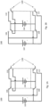
- Referring now to exemplary
Fig. 1A , a switching circuit may be shown in a parallel configuration. Two energy storage units, in this exemplary embodiment afirst battery 102 and asecond battery 104, may be connected by a set of switches. In this exemplary embodiment, these batteries may be wet-cell lead acid batteries of 12 volts and 100-amp hours each. The positive and negative terminals of each battery may be connected to switches.Switch 106 may permanently connect to the positive terminal ofbattery 104 and may connect to the positive terminal ofbattery 102 in the parallel phase. Thus, there may be a node atswitch 106 connecting the positive terminals ofbattery 102,battery 104, and the positive terminal of the output. - Still referring to the parallel phase in exemplary
Fig. 1A , anadditional switch 108 may connect to the negative terminal ofbattery 104. During the parallel phase,switch 108 may be configured to connect to the negative terminal ofbattery 102. Thus, there may be a node atswitch 108 connecting the negative terminals of thebatteries switches switch 110 may be configured to connect theoutput 120 to the node created by the positive terminals ofbattery 102 andbattery 104. At the same time,switch 112 may be configured to connect the negative terminal ofoutput 120 to the node created by the negative terminals ofbattery 102 andbattery 104. Thus, the positive terminals of the batteries and the positive terminal of the output are all connected, and the negative terminals of the batteries and the negative terminal of the output are also connected, and a parallel circuit may be formed. - Now referring to exemplary
Fig. 1B , the circuit may be shown in a series configuration. The series configuration may take place in a different phase than the parallel configuration. In the series configuration, theswitches switch 106 and switch 110 may connect the positive terminal ofbattery 104 directly to theoutput 120. The negative terminal ofbattery 104 may be connected to the positive terminal ofbattery 102, viaswitch 108. The negative terminal ofbattery 102 may be connected to theoutput 120 viaswitch 112. The switches may be any one of many types of switches or interrupters. The switches may be flipped, or commuted, at the same time. The output signals (current and voltage) may depend on the commuting or switching time between the two phases. - Referring now to exemplary
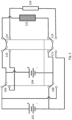
FIG. 2 , an electrical assembly may be shown with anoutput 122 which may be configured to connect to the circuit only during the series phase, and anotheroutput 124 which may be configured to connect to the circuit only during the parallel phase. This may be accomplished using theswitches - Still referring to the exemplary embodiment in
Fig. 2 , thesecondary output 124 may be disconnected from the circuit during the parallel phase. If, for example, theoutput 124 is an energy storage system that is charging from the switchingcircuit 100, it may continue to operate normally during the parallel phase and may be charged only in the series phase. - An exemplary embodiment for the purposes of analysis, such as the embodiment in
Figure 2 , may include a battery or batteries with a nominal voltage value of Vn and nominal current value of In. The load ofoutput 122 during the parallel phase may be Zparallel = (2 * Vn) / In. - In an exemplary embodiment, t1 may be the time spent in a first, parallel phase and t2 may be the time spent during the second, series phase. Further, the time T may represent the period corresponding to the fundamental frequency, so T = 1/fundamental frequency = t1 + t2. If f(t) may represent the input signal, the mean value of a signal may then be calculated using the formula:

- This formula may produce an exemplary output signal as shown in exemplary
Fig. 3 . The output signal, as illustrated inFig. 3 , may be a square signal.Fig. 3A may be the output of an exemplary current signal.Fig. 3B may be the output of an exemplary voltage signal. The width of thehorizontal line 302 may correspond to the time t1. The width ofhorizontal line 304 may correspond to the time t2. Further, the integral of the current (I) of the exemplary signal may produce the following equations:

- The integral of the voltage signal may be:

- Additionally, there may be a case where t1 = t2. In this exemplary case, the mean value of the current may be found by the following equation: (I1 + I2) / 2, and the mean value of the voltage may be found by: (V1 + V2) / 2.
- In the previously described exemplary embodiment, each battery may have a nominal current of 100A and a nominal voltage of 12V. The combined voltage when the circuit is in series may be 24V and the combined current when the circuit is in parallel may be 200A. As a result, the current mean value may be 150A and the voltage mean value may be 18V when the circuit is switching between the first phase and the second phase at an equal rate, i.e. the first phase and the second phase are of equal lengths of time. In another exemplary embodiment, the time spent in the parallel phase (ti) and the time spent in the series phase (t2) may be altered such that they are unequal. For example, if t1 is two-thirds (2/3) of the cycle, and the same nominal voltage and current is used, the current mean value may be 166.666 A and the voltage mean value may be 16V. Alternatively, if t1 is one-third (1/3) of the cycle, the current mean value may be 133.3333A and the current mean voltage may be 20V. Any ratio of t1 to t2 may be used to achieve a desired result.
- In a further exemplary embodiment, the circuit may be adjusted by a control unit capable of altering the frequency of the phases. The control unit may be able to set the switching speed or the switching time between the two phases. The switching time may be the amount of time spent in each phase. The control unit may select a switching time based on rotations per second, or any other measurement of time. There may be any number of switches or rotations per second, from 1 to infinity. The control unit may configure the circuit to be in one phase much longer than the other phase. The phases may not be in equal lengths. By changing the relative proportion of time spent in the phases, the output signal may be altered. Additionally, the control unit may be set to initially keep the circuit in a specific state. For example, the control unit may be configured to start in the parallel phase until the energy storage units become fully charged. The control unit may then begin the cycle of switching.
- The batteries may be connected to an energy source. The circuit may be configured such that the batteries are connected in series during a first phase, during which they may be connected to a load and may be discharging. Then, during a second phase, the batteries may be connected in parallel as well as to the energy source which may charge the batteries during this phase. Thus, the batteries may discharge during the first series phase and charge during the second parallel phase. During the first cycle, the battery may discharge a small amount of energy. Further, during the second cycle a similarly small amount of energy may be charged to compensate for the energy lost during the first cycle. This may improve battery performance.
- The energy source may be chosen to have a larger current output so that a larger amount of energy is charged to the battery during the parallel phase. In an exemplary embodiment, the amount of charge from the energy source during the parallel phase may exceed the amount of charge discharged by the load during the series phase, so the batteries may gain charge over time. It may be contemplated that when the battery reaches a certain level, the excess charge is prevented from reaching the battery in order to reduce the risk of overcharging. In an alternate embodiment, an energy source may be chosen which charges an amount of energy equal to the amount discharged during the series phase. In this alternate exemplary embodiment, the energy storage units may constantly hold the same amount of charge.
- Additionally, by charging and discharging the batteries during these short cycles, the circuit may have the effect of charging and discharging the batteries or energy storage systems at the same time. Typical batteries or circuits cannot charge and discharge simultaneously and instead may utilize a central controller to manage the charge and discharge cycles. Typical energy sources may be connected directly to the load or connected to an energy storage system but may not be connected to both. As a result, the energy source may be configured to either charge a battery or to drive a load, but not both. An exemplary embodiment of a simultaneous series and parallel circuit as described here may be configured such that an energy source is connected to an energy storage system which then may drive a load at the same time. The load may draw power from the battery during a first phase and the energy storage system may charge during the second phase.
- The energy source may be any type or combination of energy sources. In an exemplary embodiment, a renewable energy source may be used, although it is envisioned that other energy sources may be utilized, as desired.
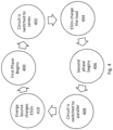
- Now referring to exemplary
Fig. 4 , a method for implementing a switching circuit, such as the circuit inFig. 2 , may be shown. In a first step, the first phase may begin 400. The control unit may begin the first phase by sending a signal to the switches. In the next step, the switches may be flipped 402 such that the circuit is switched to a series configuration. The control unit may flip the switches simultaneously. The switches may be connected to one another such that they are flipped at the same time. In a third step, the energy storage units (ESUs) may charge theload 404. The load may be a rechargeable power source. - In a fourth step, the second phase may begin 406. The control unit may be configured to start the second phase after a certain amount of time, depending on how long the first phase is. The first phase and second phase may be of different durations. In a next step, the switches may be flipped 408. During this step, the switches may be flipped to the opposite position that they were flipped to in
step 402. The switches may be flipped such that the ESUs and the load are connected in a parallel configuration. In a final step, the energy source may charge theESUs 410. In an alternate embodiment, the ESUs may continue discharging during the 2nd cycle, in the parallel phase. In this exemplary embodiment, the control unit may configure the ESUs to continue discharging so that they are connected to the load during both phases. The energy source may be connected to a switch which connects the energy source to the circuit during the second phase and connects the load to the circuit during the first phase. This switch may also be controlled by the control unit and may be flipped at the same time as the other switches. After a predetermined period of time, the first phase may once again begin 400 and a new cycle may start. - Although the previous examples may implement a switching circuit involving two batteries, it may be contemplated that the batteries may instead be any component that a user desires to be switched between series and parallel. Further, two batteries were used in the previous examples for the sake of clarity, but any number of batteries may be interconnected in a similar manner. The additional batteries may be configured to operate in additional (more than two) phases. The output may be any desirable output, such as another battery, an energy storage system, or any other electrically connected component capable of receiving an input.
- In an exemplary embodiment, the switching circuit may be implemented in an electric vehicle. The switching circuit may be configured such that the electric vehicle is powered during one phase and disconnected and charging during the other phase. In an exemplary embodiment, the same amount of energy discharged during the first phase may be charged during the second phase. During the powered phase, the battery may expend additional energy to compensate for the energy lost during the unpowered phase. However, since the battery may be activated for half the time (one out of two phases as opposed to a constant output), efficiency may be increased.
- Further, the switching circuit may allow for multiple sources of energy to be used simultaneously. For example, an electric vehicle powered by photovoltaic cells may be charged using an alternate source of energy (such as wind, gas, etc.) during solar intermittencies.
- The foregoing description and accompanying figures illustrate the principles, preferred embodiments and modes of operation of the invention. However, the invention should not be construed as being limited to the particular embodiments discussed above. Additional variations of the embodiments discussed above will be appreciated by those skilled in the art.
- Therefore, the above-described embodiments should be regarded as illustrative rather than restrictive. Accordingly, it should be appreciated that variations to those embodiments can be made by those skilled in the art without departing from the scope of the invention as defined by the following claims.
Claims (18)
- A system (100) for connecting batteries in an electrical circuit, comprising:a first energy storage unit (102) with a positive terminal and a negative terminal,a second energy storage unit (104) with a positive terminal and a negative terminal,an output device (120, 122, 124), anda control unit configured to regulate a cycle comprising a first phase and a second phase,wherein during the first phase, the negative terminal of the first energy storage unit (102) is connected to the positive terminal of the second energy storage unit (104), while the positive terminal of the first energy storage unit (102) and the negative terminal of the second energy storage unit (104) are connected to the output device (120, 122, 124), such that the first energy storage unit (102), second energy storage unit (104), and output device (120, 122) are connected in a series connection; andwherein during the second phase, the positive terminal of the first energy storage unit (102) is connected to the positive terminal of the second energy storage unit (104) while the negative terminal of the first energy storage unit (102) is connected to the negative terminal of the second energy storage unit (104) and both the positive terminals are connected to the output device (120, 124) and the negative terminals are connected to the output device (120, 124), such that the first energy storage unit (102), second energy storage unit (104), and output device are connected in parallel (120, 122),a plurality of switches (106, 110, 108, 112, 114, 116) connected to the positive and negative terminals of the energy storage units (102, 104), such that the switches are capable of configuring the circuit in a series configuration during the first phase, and then in a parallel configuration during the second phase;characterized in thatthe plurality of switches (106, 110, 108, 112, 114, 116) comprises a first switch (106) permanently connected to the positive terminal of the second energy storage unit (104), the first switch (106) being configured to connect said positive terminal of the second energy storage unit (104) to a positive terminal of the output device (120, 122) during the first phase, and to the positive terminal of the first energy storage unit (102) during the second phase;wherein the plurality of switches (106, 110, 108, 112, 114, 116) comprises a second switch (108) permanently connected to the negative terminal of the second energy storage unit (104), the second switch (108) being configured to connect said negative terminal of the second energy storage unit (104) to the positive terminal of the first energy storage unit (102) during the first phase, and to a negative terminal of the first energy storage unit (102) during the second phase;wherein the plurality of switches (106, 110, 108, 112, 114, 116) comprises a third switch (110) permanently connected to the positive terminal of the output device (120, 122, 124), the third switch (110) being configured to connect said positive terminal of the output device (120, 122, 124) to the positive terminal of second energy storage unit (104) via the first switch (106) during the first phase, and simultaneously to the positive terminal of the first energy storage unit (102) via the first switch (106) and to the positive terminal of the second storage unit (104) during the second phase; andwherein the plurality of switches (106, 110, 108, 112, 114, 116) comprises a fourth switch (112) permanently connected to the negative terminal of the output device (120, 122, 124), the fourth switch (112) being configured to connect said negative terminal of the output device (120, 124) to the negative terminal of first energy storage unit (102) during the first phase, and simultaneously to the negative terminal of the first energy storage unit (102) via the second switch (108) and to the negative terminal of the second energy storage unit (104) during the second phase.
- The system (100) of claim 1, wherein the control unit is capable of altering the relative duration of the first phase independent and the relative duration of the second phase, such that the first phase comprises 0% to 100% of the duration of the cycle, and the second phase comprises the remainder of the cycle.
- The system (100) of claim 1, wherein the control unit is one of a programable mechanical, electronic, PCB or integrated circuit chip.
- The system (100) of claim 1, wherein the energy storage unit (102, 104) is an electrical storage device capable of accepting an electrical charge.
- The system of claim 1, wherein the first energy storage unit (102) and the second energy storage unit (104) each comprise a plurality of batteries.
- The system (100) of claim 1, wherein the duration of the first phase is equal to the duration of the second phase.
- The system (100) of claim 1, wherein the first energy storage unit (102) and the second energy storage unit (104) are capacitors.
- The system (100) of claim 1, further comprising a rechargeable power source (124) connected to the output,
wherein during the second phase the control unit is further configured to connect the positive terminals of the first (102) and second (104) energy storage units to a positive terminal on the rechargeable power source (124) and the negative terminals of the energy storage units (102, 104) to a negative terminal on the rechargeable power source (124), such that the rechargeable power source (124) is connected to and receiving charge from the circuit using a parallel connection. - The system (100) of claim 1, wherein the plurality of switches (106, 108, 110, 112, 114, 116) are connected to one another such that they are all activated simultaneously.
- The system (100) of claim 1, wherein the control unit is configured to control the plurality of switches (106, 108, 110, 112, 114, 116).
- The system (100) of claim 8, wherein during the first phase the rechargeable power source (124) is disconnected from the circuit and the system (100) is instead configured to drive a load (122).
- The system (100) of claim 11, being configured such that an amount of energy is lost from the first energy storage unit (102) and second energy storage unit (104) to the load during the first phase, and then recharged to the rechargeable power source from the electric circuit during the second phase.
- The system (100) of claim 1, being configured such that the first energy storage unit (102) and the second energy storage unit (104) are initially fully charged.
- The system (100) of claim 1, wherein the control unit is configured to operate more than one cycle per second.
- The system (100) of claim 1, wherein the plurality of switches (106, 108, 110, 112, 114, 116) are interconnected such that they are flipped or change position simultaneously.
- The system (100) of claim 1, wherein the output terminal further comprises a switch (114, 116) that switches between two output devices (122, 124) every phase.
- The system (100) of claim 1, wherein the control unit is configured to alter the durations of the first phase and the second phase to produce a specific output voltage and current.
- The system (100) of claim 1, wherein the switches (106, 108, 110, 112, 114, 116) are transistors.
Applications Claiming Priority (3)
| Application Number | Priority Date | Filing Date | Title |
|---|---|---|---|
| US201862740546P | 2018-10-03 | 2018-10-03 | |
| US16/574,218 US11398735B2 (en) | 2018-10-03 | 2019-09-18 | Energy storage system and method to improve battery performance based on battery connections |
| PCT/US2019/054249 WO2020072611A1 (en) | 2018-10-03 | 2019-10-02 | Energy storage system and method to improve battery performance |
Publications (4)
| Publication Number | Publication Date |
|---|---|
| EP3837134A1 EP3837134A1 (en) | 2021-06-23 |
| EP3837134A4 EP3837134A4 (en) | 2022-04-20 |
| EP3837134B1 true EP3837134B1 (en) | 2024-09-25 |
| EP3837134C0 EP3837134C0 (en) | 2024-09-25 |
Family
ID=70052412
Family Applications (1)
| Application Number | Title | Priority Date | Filing Date |
|---|---|---|---|
| EP19868765.9A Active EP3837134B1 (en) | 2018-10-03 | 2019-10-02 | Energy storage system comprising series-parallel switching circuit |
Country Status (17)
| Country | Link |
|---|---|
| US (3) | US11398735B2 (en) |
| EP (1) | EP3837134B1 (en) |
| JP (1) | JP7606452B2 (en) |
| KR (1) | KR102939412B1 (en) |
| CN (1) | CN113039697B (en) |
| AU (2) | AU2019354416A1 (en) |
| BR (1) | BR112021005346A2 (en) |
| CA (1) | CA3114413A1 (en) |
| CL (1) | CL2021000833A1 (en) |
| CO (1) | CO2021004124A2 (en) |
| EA (1) | EA202190863A1 (en) |
| IL (1) | IL281889B2 (en) |
| MX (1) | MX2021003415A (en) |
| PH (1) | PH12021550585A1 (en) |
| SG (1) | SG11202102236PA (en) |
| WO (1) | WO2020072611A1 (en) |
| ZA (1) | ZA202102079B (en) |
Families Citing this family (4)
| Publication number | Priority date | Publication date | Assignee | Title |
|---|---|---|---|---|
| US11398735B2 (en) * | 2018-10-03 | 2022-07-26 | Switching Battery Inc. | Energy storage system and method to improve battery performance based on battery connections |
| US12040638B2 (en) * | 2018-10-03 | 2024-07-16 | Switching Battery Inc. | Energy storage system and method to improve battery performance by battery connection method |
| CN112510810B (en) * | 2020-12-07 | 2023-04-11 | 中国第一汽车股份有限公司 | Automobile and monitoring circuit of power supply system thereof |
| DE102021201760B4 (en) | 2021-02-25 | 2024-10-24 | Volkswagen Aktiengesellschaft | vehicle electrical system and motor vehicle |
Family Cites Families (36)
| Publication number | Priority date | Publication date | Assignee | Title |
|---|---|---|---|---|
| US3459957A (en) | 1967-07-19 | 1969-08-05 | Ite Imperial Corp | Voltage regulator circuit |
| US5734205A (en) | 1996-04-04 | 1998-03-31 | Jeol Ltd. | Power supply using batteries undergoing great voltage variations |
| US5994965A (en) | 1998-04-03 | 1999-11-30 | Cbs Corporation | Silicon carbide high frequency high power amplifier |
| EP1245452A1 (en) * | 2001-03-30 | 2002-10-02 | Siemens Aktiengesellschaft | Vehicle on-board network, particularly for a truck |
| JP2002315308A (en) * | 2001-04-10 | 2002-10-25 | Fujitsu Ltd | DC-DC converter and storage device |
| JP2006158073A (en) * | 2004-11-29 | 2006-06-15 | Fuji Electric Holdings Co Ltd | Capacitor charge / discharge method and power converter |
| US7489048B2 (en) | 2006-01-09 | 2009-02-10 | General Electric Company | Energy storage system for electric or hybrid vehicle |
| JP5070793B2 (en) | 2006-10-18 | 2012-11-14 | 日産自動車株式会社 | Power converter control method |
| JP2009011108A (en) * | 2007-06-29 | 2009-01-15 | Panasonic Corp | Power supply device and charger |
| JP2010178421A (en) * | 2009-01-27 | 2010-08-12 | Nissan Motor Co Ltd | Power supplying device |
| US20160211682A1 (en) | 2009-11-19 | 2016-07-21 | Tseng-Lu Chien | Plug-In AC Outlet Electric Device Has Replaceable Rechargeable Battery |
| EA201290388A1 (en) * | 2009-12-02 | 2012-12-28 | Раджендра Бабу Арумугам | WIND BATTERY CHARGING ELECTRICAL SYSTEM WITH INSULATED LOAD |
| JP5543195B2 (en) * | 2009-12-28 | 2014-07-09 | 有限会社オーエイチケー研究所 | Battery charger |
| US8723344B1 (en) * | 2010-06-24 | 2014-05-13 | James Dierickx | Energy harvesting system |
| WO2012063385A1 (en) | 2010-11-12 | 2012-05-18 | Three Eye Co., Ltd. | Motor-driving apparatus capable of charging vehicle battery |
| FR2972304A1 (en) * | 2011-03-02 | 2012-09-07 | Commissariat Energie Atomique | BATTERY WITH INDIVIDUAL MANAGEMENT OF CELLS |
| FR2975238B1 (en) * | 2011-05-09 | 2016-06-10 | Commissariat Energie Atomique | METHOD FOR MANAGING AND DIAGNOSING A BATTERY |
| JP5745465B2 (en) * | 2012-06-20 | 2015-07-08 | 本田技研工業株式会社 | Power supply |
| CN103236832B (en) * | 2013-05-06 | 2015-08-12 | 艾何示 | The control circuit of logical-sequential control circuit and charged in parallel discharged in series |
| JP2015095912A (en) * | 2013-11-08 | 2015-05-18 | 住友電装株式会社 | Power storage device |
| WO2015195321A1 (en) | 2014-06-20 | 2015-12-23 | Ioxus, Inc. | Engine start and battery support module |
| US10106110B1 (en) | 2014-07-23 | 2018-10-23 | Ganiere Innovations, L.L.C. | Direct current power management system |
| TWI614964B (en) | 2014-08-01 | 2018-02-11 | 技嘉科技股份有限公司 | Fast low voltage rechargeable battery |
| JP6164195B2 (en) * | 2014-11-06 | 2017-07-19 | トヨタ自動車株式会社 | Power converter |
| US10784680B2 (en) * | 2015-01-23 | 2020-09-22 | Elevate Technologies Corporation | Adaptable recharging and lighting station and methods of using the same |
| DE102015106773A1 (en) * | 2015-04-30 | 2016-11-03 | Dr. Ing. H.C. F. Porsche Aktiengesellschaft | Battery system with battery control |
| DE102015222264A1 (en) | 2015-11-11 | 2017-05-11 | Viessmann Werke Gmbh & Co Kg | METHOD AND DEVICE FOR ENERGY MANAGEMENT OF AN ENERGY STORAGE FOR AVOIDING MICROCYCLES |
| CN108353486B (en) * | 2015-12-01 | 2019-12-31 | 飞利浦照明控股有限公司 | coded light modulation device |
| NZ742209A (en) * | 2015-12-11 | 2019-04-26 | Milwaukee Electric Tool Corp | Method and apparatus for connecting a plurality of battery cells in series or parallel |
| DE102016223470A1 (en) | 2015-12-18 | 2017-06-22 | Robert Bosch Gmbh | Charging circuit and charging method for an electrical energy storage system |
| GB2556914A (en) * | 2016-11-25 | 2018-06-13 | Dyson Technology Ltd | Battery system |
| KR20180133018A (en) * | 2017-06-02 | 2018-12-13 | 현대자동차주식회사 | Battery system for vehicle and controlling method |
| DE102018106309A1 (en) * | 2018-03-19 | 2019-09-19 | Dr. Ing. H.C. F. Porsche Aktiengesellschaft | energy storage |
| JP6853805B2 (en) * | 2018-09-13 | 2021-03-31 | 株式会社Subaru | Electric vehicle |
| US12040638B2 (en) * | 2018-10-03 | 2024-07-16 | Switching Battery Inc. | Energy storage system and method to improve battery performance by battery connection method |
| US11398735B2 (en) * | 2018-10-03 | 2022-07-26 | Switching Battery Inc. | Energy storage system and method to improve battery performance based on battery connections |
-
2019
- 2019-09-18 US US16/574,218 patent/US11398735B2/en active Active
- 2019-10-02 CN CN201980065092.2A patent/CN113039697B/en active Active
- 2019-10-02 KR KR1020217010127A patent/KR102939412B1/en active Active
- 2019-10-02 AU AU2019354416A patent/AU2019354416A1/en not_active Abandoned
- 2019-10-02 JP JP2021518875A patent/JP7606452B2/en active Active
- 2019-10-02 MX MX2021003415A patent/MX2021003415A/en unknown
- 2019-10-02 BR BR112021005346-8A patent/BR112021005346A2/en not_active Application Discontinuation
- 2019-10-02 EP EP19868765.9A patent/EP3837134B1/en active Active
- 2019-10-02 WO PCT/US2019/054249 patent/WO2020072611A1/en not_active Ceased
- 2019-10-02 EA EA202190863A patent/EA202190863A1/en unknown
- 2019-10-02 CA CA3114413A patent/CA3114413A1/en active Pending
- 2019-10-02 SG SG11202102236PA patent/SG11202102236PA/en unknown
- 2019-10-09 IL IL281889A patent/IL281889B2/en unknown
-
2021
- 2021-03-17 PH PH12021550585A patent/PH12021550585A1/en unknown
- 2021-03-26 ZA ZA2021/02079A patent/ZA202102079B/en unknown
- 2021-04-01 CL CL2021000833A patent/CL2021000833A1/en unknown
- 2021-04-05 CO CONC2021/0004124A patent/CO2021004124A2/en unknown
-
2022
- 2022-07-25 US US17/872,236 patent/US11799301B2/en active Active
-
2023
- 2023-10-18 US US18/489,048 patent/US20240047980A1/en not_active Abandoned
-
2025
- 2025-08-11 AU AU2025213697A patent/AU2025213697B2/en active Active
Also Published As
| Publication number | Publication date |
|---|---|
| AU2025213697B2 (en) | 2025-10-30 |
| JP2022502997A (en) | 2022-01-11 |
| MX2021003415A (en) | 2021-06-15 |
| EA202190863A1 (en) | 2021-10-01 |
| CN113039697B (en) | 2025-02-18 |
| KR20210065119A (en) | 2021-06-03 |
| IL281889B1 (en) | 2024-11-01 |
| SG11202102236PA (en) | 2021-04-29 |
| EP3837134A4 (en) | 2022-04-20 |
| CA3114413A1 (en) | 2020-04-09 |
| US20240047980A1 (en) | 2024-02-08 |
| CL2021000833A1 (en) | 2021-10-22 |
| IL281889A (en) | 2021-05-31 |
| IL281889B2 (en) | 2025-03-01 |
| AU2019354416A1 (en) | 2021-04-22 |
| US11799301B2 (en) | 2023-10-24 |
| US11398735B2 (en) | 2022-07-26 |
| AU2025213697A1 (en) | 2025-08-28 |
| BR112021005346A2 (en) | 2021-06-15 |
| WO2020072611A1 (en) | 2020-04-09 |
| US20220368139A1 (en) | 2022-11-17 |
| JP7606452B2 (en) | 2024-12-25 |
| EP3837134A1 (en) | 2021-06-23 |
| EP3837134C0 (en) | 2024-09-25 |
| KR102939412B1 (en) | 2026-03-16 |
| CO2021004124A2 (en) | 2021-04-30 |
| PH12021550585A1 (en) | 2021-11-22 |
| US20200112184A1 (en) | 2020-04-09 |
| CN113039697A (en) | 2021-06-25 |
| ZA202102079B (en) | 2023-12-20 |
Similar Documents
| Publication | Publication Date | Title |
|---|---|---|
| US11799301B2 (en) | Energy storage system and method to improve battery performance based on battery connections | |
| US11685267B2 (en) | Battery with a battery cell and method of operation thereof | |
| EP3286816B1 (en) | A power supply system | |
| KR101677679B1 (en) | Power management circuit for rechargeable battery stack | |
| US7847436B2 (en) | Modular power supply | |
| CN111357148A (en) | Power storage module and power supply system | |
| JP2014511662A (en) | Controllable energy storage device and method for operating a controllable energy storage device | |
| KR20220058064A (en) | Pulsed Power Modulator based on Modular Structure | |
| US11316352B2 (en) | Battery management | |
| JP2009148110A (en) | Charger / discharger and power supply using the same | |
| JP2013192371A (en) | Power storage device, charging method, and discharging method | |
| JP4724726B2 (en) | DC power supply system and charging method thereof | |
| JP2009296719A (en) | Dc backup power system and method of charging the same | |
| KR102028254B1 (en) | Vehicle, in particular an electric vehicle or a hybrid vehicle, and method for charging an energy storage cell of a vehicle | |
| EP4238805A1 (en) | Vehicle power source device | |
| JP2002142375A (en) | Power storage device and control method thereof | |
| CN111052535A (en) | Solar power generation/storage unit and solar power generation/storage system | |
| OA20175A (en) | Energy storage system and method to improve battery performance. | |
| HK40056316A (en) | Energy storage system and method to improve battery performance | |
| Abdelmoaty et al. | A single-step, single-inductor energy-harvestingbased power supply platform with a regulated battery charger for mobile applications | |
| EA042780B1 (en) | ENERGY STORAGE SYSTEM AND METHOD FOR INCREASING BATTERY EFFICIENCY | |
| JP2026046959A (en) | Energy storage system | |
| KR20160111883A (en) | Device for Lengthening Life Span of Battery, Power System, and Solar Street Light therewith | |
| JP2006014545A (en) | Step-up device | |
| JP2018125946A (en) | Power storage device |
Legal Events
| Date | Code | Title | Description |
|---|---|---|---|
| STAA | Information on the status of an ep patent application or granted ep patent |
Free format text: STATUS: THE INTERNATIONAL PUBLICATION HAS BEEN MADE |
|
| PUAI | Public reference made under article 153(3) epc to a published international application that has entered the european phase |
Free format text: ORIGINAL CODE: 0009012 |
|
| STAA | Information on the status of an ep patent application or granted ep patent |
Free format text: STATUS: REQUEST FOR EXAMINATION WAS MADE |
|
| 17P | Request for examination filed |
Effective date: 20210315 |
|
| AK | Designated contracting states |
Kind code of ref document: A1 Designated state(s): AL AT BE BG CH CY CZ DE DK EE ES FI FR GB GR HR HU IE IS IT LI LT LU LV MC MK MT NL NO PL PT RO RS SE SI SK SM TR |
|
| DAV | Request for validation of the european patent (deleted) | ||
| DAX | Request for extension of the european patent (deleted) | ||
| REG | Reference to a national code |
Ref country code: DE Ref legal event code: R079 Free format text: PREVIOUS MAIN CLASS: B60L0008000000 Ipc: H02J0007000000 Ref document number: 602019059556 Country of ref document: DE |
|
| A4 | Supplementary search report drawn up and despatched |
Effective date: 20220323 |
|
| RIC1 | Information provided on ipc code assigned before grant |
Ipc: H02J 7/36 20060101ALI20220318BHEP Ipc: H02J 7/00 20060101AFI20220318BHEP |
|
| RAP1 | Party data changed (applicant data changed or rights of an application transferred) |
Owner name: SWITCHING BATTERY, INC. |
|
| RIN1 | Information on inventor provided before grant (corrected) |
Inventor name: CHETTIAR, VESHANT Inventor name: CHETTIAR, KANNAPPAN KARUPPAN |
|
| GRAP | Despatch of communication of intention to grant a patent |
Free format text: ORIGINAL CODE: EPIDOSNIGR1 |
|
| STAA | Information on the status of an ep patent application or granted ep patent |
Free format text: STATUS: GRANT OF PATENT IS INTENDED |
|
| RIC1 | Information provided on ipc code assigned before grant |
Ipc: H02J 7/36 20060101ALI20240404BHEP Ipc: H02J 7/00 20060101AFI20240404BHEP |
|
| INTG | Intention to grant announced |
Effective date: 20240429 |
|
| GRAS | Grant fee paid |
Free format text: ORIGINAL CODE: EPIDOSNIGR3 |
|
| GRAA | (expected) grant |
Free format text: ORIGINAL CODE: 0009210 |
|
| STAA | Information on the status of an ep patent application or granted ep patent |
Free format text: STATUS: THE PATENT HAS BEEN GRANTED |
|
| AK | Designated contracting states |
Kind code of ref document: B1 Designated state(s): AL AT BE BG CH CY CZ DE DK EE ES FI FR GB GR HR HU IE IS IT LI LT LU LV MC MK MT NL NO PL PT RO RS SE SI SK SM TR |
|
| REG | Reference to a national code |
Ref country code: GB Ref legal event code: FG4D |
|
| REG | Reference to a national code |
Ref country code: CH Ref legal event code: EP |
|
| REG | Reference to a national code |
Ref country code: DE Ref legal event code: R096 Ref document number: 602019059556 Country of ref document: DE |
|
| REG | Reference to a national code |
Ref country code: IE Ref legal event code: FG4D |
|
| U01 | Request for unitary effect filed |
Effective date: 20241008 |
|
| U07 | Unitary effect registered |
Designated state(s): AT BE BG DE DK EE FI FR IT LT LU LV MT NL PT RO SE SI Effective date: 20241028 |
|
| U20 | Renewal fee for the european patent with unitary effect paid |
Year of fee payment: 6 Effective date: 20241028 |
|
| PG25 | Lapsed in a contracting state [announced via postgrant information from national office to epo] |
Ref country code: NO Free format text: LAPSE BECAUSE OF FAILURE TO SUBMIT A TRANSLATION OF THE DESCRIPTION OR TO PAY THE FEE WITHIN THE PRESCRIBED TIME-LIMIT Effective date: 20241225 |
|
| PG25 | Lapsed in a contracting state [announced via postgrant information from national office to epo] |
Ref country code: GR Free format text: LAPSE BECAUSE OF FAILURE TO SUBMIT A TRANSLATION OF THE DESCRIPTION OR TO PAY THE FEE WITHIN THE PRESCRIBED TIME-LIMIT Effective date: 20241226 |
|
| PGFP | Annual fee paid to national office [announced via postgrant information from national office to epo] |
Ref country code: GB Payment date: 20241028 Year of fee payment: 6 |
|
| PG25 | Lapsed in a contracting state [announced via postgrant information from national office to epo] |
Ref country code: RS Free format text: LAPSE BECAUSE OF FAILURE TO SUBMIT A TRANSLATION OF THE DESCRIPTION OR TO PAY THE FEE WITHIN THE PRESCRIBED TIME-LIMIT Effective date: 20241225 |
|
| PG25 | Lapsed in a contracting state [announced via postgrant information from national office to epo] |
Ref country code: RS Free format text: LAPSE BECAUSE OF FAILURE TO SUBMIT A TRANSLATION OF THE DESCRIPTION OR TO PAY THE FEE WITHIN THE PRESCRIBED TIME-LIMIT Effective date: 20241225 Ref country code: NO Free format text: LAPSE BECAUSE OF FAILURE TO SUBMIT A TRANSLATION OF THE DESCRIPTION OR TO PAY THE FEE WITHIN THE PRESCRIBED TIME-LIMIT Effective date: 20241225 Ref country code: GR Free format text: LAPSE BECAUSE OF FAILURE TO SUBMIT A TRANSLATION OF THE DESCRIPTION OR TO PAY THE FEE WITHIN THE PRESCRIBED TIME-LIMIT Effective date: 20241226 |
|
| PG25 | Lapsed in a contracting state [announced via postgrant information from national office to epo] |
Ref country code: IS Free format text: LAPSE BECAUSE OF FAILURE TO SUBMIT A TRANSLATION OF THE DESCRIPTION OR TO PAY THE FEE WITHIN THE PRESCRIBED TIME-LIMIT Effective date: 20250125 |
|
| PG25 | Lapsed in a contracting state [announced via postgrant information from national office to epo] |
Ref country code: SM Free format text: LAPSE BECAUSE OF FAILURE TO SUBMIT A TRANSLATION OF THE DESCRIPTION OR TO PAY THE FEE WITHIN THE PRESCRIBED TIME-LIMIT Effective date: 20240925 |
|
| PG25 | Lapsed in a contracting state [announced via postgrant information from national office to epo] |
Ref country code: ES Free format text: LAPSE BECAUSE OF FAILURE TO SUBMIT A TRANSLATION OF THE DESCRIPTION OR TO PAY THE FEE WITHIN THE PRESCRIBED TIME-LIMIT Effective date: 20240925 |
|
| PG25 | Lapsed in a contracting state [announced via postgrant information from national office to epo] |
Ref country code: PL Free format text: LAPSE BECAUSE OF FAILURE TO SUBMIT A TRANSLATION OF THE DESCRIPTION OR TO PAY THE FEE WITHIN THE PRESCRIBED TIME-LIMIT Effective date: 20240925 Ref country code: CZ Free format text: LAPSE BECAUSE OF FAILURE TO SUBMIT A TRANSLATION OF THE DESCRIPTION OR TO PAY THE FEE WITHIN THE PRESCRIBED TIME-LIMIT Effective date: 20240925 |
|
| PG25 | Lapsed in a contracting state [announced via postgrant information from national office to epo] |
Ref country code: SK Free format text: LAPSE BECAUSE OF FAILURE TO SUBMIT A TRANSLATION OF THE DESCRIPTION OR TO PAY THE FEE WITHIN THE PRESCRIBED TIME-LIMIT Effective date: 20240925 |
|
| REG | Reference to a national code |
Ref country code: CH Ref legal event code: PL |
|
| PG25 | Lapsed in a contracting state [announced via postgrant information from national office to epo] |
Ref country code: MC Free format text: LAPSE BECAUSE OF FAILURE TO SUBMIT A TRANSLATION OF THE DESCRIPTION OR TO PAY THE FEE WITHIN THE PRESCRIBED TIME-LIMIT Effective date: 20240925 |
|
| PG25 | Lapsed in a contracting state [announced via postgrant information from national office to epo] |
Ref country code: CH Free format text: LAPSE BECAUSE OF NON-PAYMENT OF DUE FEES Effective date: 20241031 |
|
| PLBE | No opposition filed within time limit |
Free format text: ORIGINAL CODE: 0009261 |
|
| STAA | Information on the status of an ep patent application or granted ep patent |
Free format text: STATUS: NO OPPOSITION FILED WITHIN TIME LIMIT |
|
| 26N | No opposition filed |
Effective date: 20250626 |
|
| PG25 | Lapsed in a contracting state [announced via postgrant information from national office to epo] |
Ref country code: IE Free format text: LAPSE BECAUSE OF NON-PAYMENT OF DUE FEES Effective date: 20241002 |
|
| PG25 | Lapsed in a contracting state [announced via postgrant information from national office to epo] |
Ref country code: HR Free format text: LAPSE BECAUSE OF FAILURE TO SUBMIT A TRANSLATION OF THE DESCRIPTION OR TO PAY THE FEE WITHIN THE PRESCRIBED TIME-LIMIT Effective date: 20240925 |
|
| PG25 | Lapsed in a contracting state [announced via postgrant information from national office to epo] |
Ref country code: CY Free format text: LAPSE BECAUSE OF FAILURE TO SUBMIT A TRANSLATION OF THE DESCRIPTION OR TO PAY THE FEE WITHIN THE PRESCRIBED TIME-LIMIT; INVALID AB INITIO Effective date: 20191002 |
|
| PG25 | Lapsed in a contracting state [announced via postgrant information from national office to epo] |
Ref country code: HU Free format text: LAPSE BECAUSE OF FAILURE TO SUBMIT A TRANSLATION OF THE DESCRIPTION OR TO PAY THE FEE WITHIN THE PRESCRIBED TIME-LIMIT; INVALID AB INITIO Effective date: 20191002 |