EP3836810B1 - Aerosol-generating device for use with an aerosol-generating article comprising means for article identification - Google Patents
Aerosol-generating device for use with an aerosol-generating article comprising means for article identification Download PDFInfo
- Publication number
- EP3836810B1 EP3836810B1 EP19755616.0A EP19755616A EP3836810B1 EP 3836810 B1 EP3836810 B1 EP 3836810B1 EP 19755616 A EP19755616 A EP 19755616A EP 3836810 B1 EP3836810 B1 EP 3836810B1
- Authority
- EP
- European Patent Office
- Prior art keywords
- aerosol
- article
- field generator
- receiving cavity
- generating
- Prior art date
- Legal status (The legal status is an assumption and is not a legal conclusion. Google has not performed a legal analysis and makes no representation as to the accuracy of the status listed.)
- Active
Links
- 238000010438 heat treatment Methods 0.000 claims description 59
- 239000000758 substrate Substances 0.000 claims description 54
- 230000006698 induction Effects 0.000 claims description 40
- 230000008859 change Effects 0.000 claims description 31
- 230000035699 permeability Effects 0.000 claims description 16
- 239000004020 conductor Substances 0.000 claims description 3
- 239000011888 foil Substances 0.000 claims description 3
- 235000012771 pancakes Nutrition 0.000 claims description 3
- 239000010409 thin film Substances 0.000 claims description 3
- 239000000463 material Substances 0.000 description 24
- 239000000443 aerosol Substances 0.000 description 12
- PEDCQBHIVMGVHV-UHFFFAOYSA-N Glycerine Chemical compound OCC(O)CO PEDCQBHIVMGVHV-UHFFFAOYSA-N 0.000 description 6
- 241000208125 Nicotiana Species 0.000 description 6
- 235000002637 Nicotiana tabacum Nutrition 0.000 description 6
- 229910052782 aluminium Inorganic materials 0.000 description 6
- XAGFODPZIPBFFR-UHFFFAOYSA-N aluminium Chemical compound [Al] XAGFODPZIPBFFR-UHFFFAOYSA-N 0.000 description 6
- 150000001875 compounds Chemical class 0.000 description 6
- 229910052751 metal Inorganic materials 0.000 description 6
- 239000002184 metal Substances 0.000 description 6
- 235000019504 cigarettes Nutrition 0.000 description 5
- 230000005672 electromagnetic field Effects 0.000 description 5
- 238000003780 insertion Methods 0.000 description 5
- 230000037431 insertion Effects 0.000 description 5
- XEEYBQQBJWHFJM-UHFFFAOYSA-N Iron Chemical compound [Fe] XEEYBQQBJWHFJM-UHFFFAOYSA-N 0.000 description 4
- PXHVJJICTQNCMI-UHFFFAOYSA-N Nickel Chemical compound [Ni] PXHVJJICTQNCMI-UHFFFAOYSA-N 0.000 description 4
- 230000000694 effects Effects 0.000 description 4
- 230000001939 inductive effect Effects 0.000 description 4
- 239000010410 layer Substances 0.000 description 4
- BASFCYQUMIYNBI-UHFFFAOYSA-N platinum Chemical compound [Pt] BASFCYQUMIYNBI-UHFFFAOYSA-N 0.000 description 4
- 229910001220 stainless steel Inorganic materials 0.000 description 4
- 238000004804 winding Methods 0.000 description 4
- DNIAPMSPPWPWGF-UHFFFAOYSA-N Propylene glycol Chemical compound CC(O)CO DNIAPMSPPWPWGF-UHFFFAOYSA-N 0.000 description 3
- 238000013461 design Methods 0.000 description 3
- 235000011187 glycerol Nutrition 0.000 description 3
- 239000007788 liquid Substances 0.000 description 3
- 230000003071 parasitic effect Effects 0.000 description 3
- 230000002093 peripheral effect Effects 0.000 description 3
- 230000000704 physical effect Effects 0.000 description 3
- 239000004033 plastic Substances 0.000 description 3
- 229920003023 plastic Polymers 0.000 description 3
- 238000007789 sealing Methods 0.000 description 3
- 229910000975 Carbon steel Inorganic materials 0.000 description 2
- 239000004696 Poly ether ether ketone Substances 0.000 description 2
- 230000004913 activation Effects 0.000 description 2
- 238000001994 activation Methods 0.000 description 2
- 229910045601 alloy Inorganic materials 0.000 description 2
- 239000000956 alloy Substances 0.000 description 2
- 230000004323 axial length Effects 0.000 description 2
- 230000009286 beneficial effect Effects 0.000 description 2
- 239000010962 carbon steel Substances 0.000 description 2
- 239000000919 ceramic Substances 0.000 description 2
- 238000001816 cooling Methods 0.000 description 2
- 238000001514 detection method Methods 0.000 description 2
- 239000000428 dust Substances 0.000 description 2
- 239000000796 flavoring agent Substances 0.000 description 2
- 239000012530 fluid Substances 0.000 description 2
- 229910052742 iron Inorganic materials 0.000 description 2
- 239000007769 metal material Substances 0.000 description 2
- 229910052759 nickel Inorganic materials 0.000 description 2
- 229910052697 platinum Inorganic materials 0.000 description 2
- 229920002530 polyetherether ketone Polymers 0.000 description 2
- 230000035945 sensitivity Effects 0.000 description 2
- 239000007787 solid Substances 0.000 description 2
- 239000000126 substance Substances 0.000 description 2
- 229910000859 α-Fe Inorganic materials 0.000 description 2
- SNICXCGAKADSCV-JTQLQIEISA-N (-)-Nicotine Chemical compound CN1CCC[C@H]1C1=CC=CN=C1 SNICXCGAKADSCV-JTQLQIEISA-N 0.000 description 1
- 239000010752 BS 2869 Class D Substances 0.000 description 1
- 239000010753 BS 2869 Class E Substances 0.000 description 1
- HBBGRARXTFLTSG-UHFFFAOYSA-N Lithium ion Chemical compound [Li+] HBBGRARXTFLTSG-UHFFFAOYSA-N 0.000 description 1
- 239000000654 additive Substances 0.000 description 1
- 230000002411 adverse Effects 0.000 description 1
- 239000003990 capacitor Substances 0.000 description 1
- 229920002301 cellulose acetate Polymers 0.000 description 1
- 239000003795 chemical substances by application Substances 0.000 description 1
- 238000002485 combustion reaction Methods 0.000 description 1
- 238000004891 communication Methods 0.000 description 1
- 230000007797 corrosion Effects 0.000 description 1
- 238000005260 corrosion Methods 0.000 description 1
- 238000010586 diagram Methods 0.000 description 1
- 230000005684 electric field Effects 0.000 description 1
- 239000012777 electrically insulating material Substances 0.000 description 1
- 230000005674 electromagnetic induction Effects 0.000 description 1
- 230000001747 exhibiting effect Effects 0.000 description 1
- 238000000605 extraction Methods 0.000 description 1
- 239000000835 fiber Substances 0.000 description 1
- 235000019634 flavors Nutrition 0.000 description 1
- 230000004907 flux Effects 0.000 description 1
- 239000003349 gelling agent Substances 0.000 description 1
- 239000004615 ingredient Substances 0.000 description 1
- 230000003993 interaction Effects 0.000 description 1
- 229910001416 lithium ion Inorganic materials 0.000 description 1
- GELKBWJHTRAYNV-UHFFFAOYSA-K lithium iron phosphate Chemical compound [Li+].[Fe+2].[O-]P([O-])([O-])=O GELKBWJHTRAYNV-UHFFFAOYSA-K 0.000 description 1
- 238000004519 manufacturing process Methods 0.000 description 1
- 238000005259 measurement Methods 0.000 description 1
- 229960002715 nicotine Drugs 0.000 description 1
- SNICXCGAKADSCV-UHFFFAOYSA-N nicotine Natural products CN1CCCC1C1=CC=CN=C1 SNICXCGAKADSCV-UHFFFAOYSA-N 0.000 description 1
- 238000013021 overheating Methods 0.000 description 1
- 239000002245 particle Substances 0.000 description 1
- 230000010363 phase shift Effects 0.000 description 1
- 239000011148 porous material Substances 0.000 description 1
- 230000001681 protective effect Effects 0.000 description 1
- 230000001007 puffing effect Effects 0.000 description 1
- 239000002356 single layer Substances 0.000 description 1
- 239000000779 smoke Substances 0.000 description 1
- 230000000391 smoking effect Effects 0.000 description 1
- 238000012546 transfer Methods 0.000 description 1
Images

Classifications
-
- A—HUMAN NECESSITIES
- A24—TOBACCO; CIGARS; CIGARETTES; SIMULATED SMOKING DEVICES; SMOKERS' REQUISITES
- A24F—SMOKERS' REQUISITES; MATCH BOXES; SIMULATED SMOKING DEVICES
- A24F40/00—Electrically operated smoking devices; Component parts thereof; Manufacture thereof; Maintenance or testing thereof; Charging means specially adapted therefor
- A24F40/50—Control or monitoring
- A24F40/51—Arrangement of sensors
-
- A—HUMAN NECESSITIES
- A24—TOBACCO; CIGARS; CIGARETTES; SIMULATED SMOKING DEVICES; SMOKERS' REQUISITES
- A24D—CIGARS; CIGARETTES; TOBACCO SMOKE FILTERS; MOUTHPIECES FOR CIGARS OR CIGARETTES; MANUFACTURE OF TOBACCO SMOKE FILTERS OR MOUTHPIECES
- A24D1/00—Cigars; Cigarettes
- A24D1/02—Cigars; Cigarettes with special covers
-
- A—HUMAN NECESSITIES
- A24—TOBACCO; CIGARS; CIGARETTES; SIMULATED SMOKING DEVICES; SMOKERS' REQUISITES
- A24D—CIGARS; CIGARETTES; TOBACCO SMOKE FILTERS; MOUTHPIECES FOR CIGARS OR CIGARETTES; MANUFACTURE OF TOBACCO SMOKE FILTERS OR MOUTHPIECES
- A24D1/00—Cigars; Cigarettes
- A24D1/20—Cigarettes specially adapted for simulated smoking devices
-
- A—HUMAN NECESSITIES
- A24—TOBACCO; CIGARS; CIGARETTES; SIMULATED SMOKING DEVICES; SMOKERS' REQUISITES
- A24F—SMOKERS' REQUISITES; MATCH BOXES; SIMULATED SMOKING DEVICES
- A24F40/00—Electrically operated smoking devices; Component parts thereof; Manufacture thereof; Maintenance or testing thereof; Charging means specially adapted therefor
- A24F40/20—Devices using solid inhalable precursors
-
- A—HUMAN NECESSITIES
- A24—TOBACCO; CIGARS; CIGARETTES; SIMULATED SMOKING DEVICES; SMOKERS' REQUISITES
- A24F—SMOKERS' REQUISITES; MATCH BOXES; SIMULATED SMOKING DEVICES
- A24F40/00—Electrically operated smoking devices; Component parts thereof; Manufacture thereof; Maintenance or testing thereof; Charging means specially adapted therefor
- A24F40/40—Constructional details, e.g. connection of cartridges and battery parts
- A24F40/46—Shape or structure of electric heating means
- A24F40/465—Shape or structure of electric heating means specially adapted for induction heating
-
- A—HUMAN NECESSITIES
- A24—TOBACCO; CIGARS; CIGARETTES; SIMULATED SMOKING DEVICES; SMOKERS' REQUISITES
- A24F—SMOKERS' REQUISITES; MATCH BOXES; SIMULATED SMOKING DEVICES
- A24F40/00—Electrically operated smoking devices; Component parts thereof; Manufacture thereof; Maintenance or testing thereof; Charging means specially adapted therefor
- A24F40/50—Control or monitoring
- A24F40/53—Monitoring, e.g. fault detection
-
- A—HUMAN NECESSITIES
- A24—TOBACCO; CIGARS; CIGARETTES; SIMULATED SMOKING DEVICES; SMOKERS' REQUISITES
- A24F—SMOKERS' REQUISITES; MATCH BOXES; SIMULATED SMOKING DEVICES
- A24F40/00—Electrically operated smoking devices; Component parts thereof; Manufacture thereof; Maintenance or testing thereof; Charging means specially adapted therefor
- A24F40/50—Control or monitoring
- A24F40/57—Temperature control
-
- H—ELECTRICITY
- H05—ELECTRIC TECHNIQUES NOT OTHERWISE PROVIDED FOR
- H05B—ELECTRIC HEATING; ELECTRIC LIGHT SOURCES NOT OTHERWISE PROVIDED FOR; CIRCUIT ARRANGEMENTS FOR ELECTRIC LIGHT SOURCES, IN GENERAL
- H05B6/00—Heating by electric, magnetic or electromagnetic fields
- H05B6/02—Induction heating
- H05B6/36—Coil arrangements
Definitions
- the present invention relates to an electrically heated aerosol-generating device for use with an aerosol-generating article comprising means for article identification.
- Aerosol-generating systems based on electrically heating aerosol-forming substrates are generally known from prior art. Typically, these systems comprise two components: an aerosol-generating article including the aerosol-forming substrate to be heated, and an aerosol-generating device, wherein the device comprises a receiving cavity for receiving the article and an electrical heater, for example a resistive or an inductive heater, for heating the substrate within the article when the article is inserted into the receiving cavity.
- an electrical heater for example a resistive or an inductive heater
- each electrically heated aerosol-generating device is designed for use with a specific type of an aerosol-generating article. This is due to the unique design of each aerosol-generating system that is defined by the specific type of substrate and its specific requirements for a well-controlled heating process. Otherwise, using an article with an aerosol-generating device which the article is not explicitly designed for may provide a different smoking experience for the user. In particular, using non-suitable articles may lead to overheating of the aerosol-forming substrate, thus causing an undesired combustion of the substrate. Even more, using articles which are non-compatible with a specific type of device may also damage the system.
- aerosol-generating systems such as described, for example, in WO 99/20940 A1 - comprising means that are configured to identify compatible articles and to prevent usage of non-compatible articles, such means often are susceptible to faults, in particular fault detection such that articles actually suitable are not recognized or identified properly. Also, there are means for article identification which may be easily circumvented, both intentionally and non-intentionally.
- an aerosol-generating device for use with an aerosol-generating article, including improved means for article identification, in particular which provide increased difficulty to use non-compatible or counterfeit articles with the device.
- an electrically heating aerosol-generating device for use with an aerosol-generating article, wherein the article includes an aerosol-forming substrate to be heated by the device.
- the device comprises a device housing including a receiving cavity within a proximal portion of the device for receiving at least a portion of the aerosol-generating article.
- the device further comprises at least one electrical heating device for heating an aerosol-forming substrate within the article when the article is received in the receiving cavity.
- the device also comprises a separating wall arranged adjacent to a distal end portion of the receiving cavity. The separating wall separates the receiving cavity within the proximal portion of the device from a distal portion of the device.
- the device comprises a sensing circuitry comprising a field generator.
- the sensing circuitry is configured to measure a change of at least one property of the field generator caused by the presence of an indicator arranged at or within the article when the article is received in the receiving cavity.
- the field generator is arranged adjacent to a distal end portion of the receiving cavity opposite to a proximal end portion of the receiving cavity within the separating wall or circumferentially around a perimeter or outer circumference of the separating wall.
- identification means are arranged about the entrance of the receiving cavity - which typically is located at the very proximal end of the device - article identification is likely to be susceptible to external influences, such as stray electromagnetic fields originating from parasitic field source in the surroundings of the device.
- identification means based on electromagnetic induction may be, for example, identification means including induction coils configured to measure a change of an inductance caused by the presence of an inductive indicator within the article when the article is received in the receiving cavity.
- parasitic electromagnetic fields may cause adverse induction effects in the induction coil causing article identification, even of suitable articles, to fail.
- article identification becomes less reliable the more the induction coil is exposed to such parasitic field sources.
- the field generator according to the present invention is arranged adjacent to a distal end portion of the receiving cavity opposite to a proximal end portion of the receiving cavity.
- this arrangement provides sufficient shielding of the field generator from stray electromagnetic fields by the device itself. Accordingly, a disturbance of the field generated by the field generator when the article is introduced into the receiving cavity occurs in a well-shielded area under stable, that is, reproducible electromagnetic conditions.
- the aerosol-generating device according to the present invention allows for article identification that is significantly improved as compared to other devices known from prior art.
- the field generator may be of any type and may have any configuration, shape and arrangement within the device housing suitable to sense the presence of the indicator arranged at or within the article when the article is introduced into the receiving cavity.
- the field generator is arranged about a distal end of the receiving cavity.
- the term "field generator” refers to an apparatus which is able to act as a source for a field, that is, the field generator may be configured to generate a field. Accordingly, the field generator may also be denoted as field source.
- the field may be an electrical field, a magnetic field, or an electromagnetic field.
- the field generator may comprise, for example, an induction coil, an antenna, or a magnet, in particular an electromagnet or a permanent magnet.
- the field generator is preferably an induction coil.
- the induction coil may be a helical coil or a flat spiral coil, in particular a pancake coil or a flat curved spiral coil.
- Use of a flat spiral coil allows for compact design that is robust and inexpensive to manufacture.
- Use of a helical induction coil advantageously provides a substantially homogeneous field configuration in the interior of the coil.
- a "flat spiral coil” means a coil that is a generally planar coil, wherein the axis of winding of the coil is normal to the surface in which the coil lies.
- the flat spiral induction can have any desired shape within the plane of the coil.
- the flat spiral coil may have a circular shape or may have a generally oblong or rectangular shape.
- the term "flat spiral coil” as used herein covers both, coils that are planar as well as flat spiral coils that are shaped to conform to a curved surface.
- the induction coil may be a "curved" planar coil arranged at the circumference of a preferably cylindrical coil support, for example ferrite core.
- the flat spiral coil may comprise for example two layers of a four-turn flat spiral coil or a single layer of four-turn flat spiral coil.
- the induction coil may comprise a protective cover or layer.
- the indicator presence of the indicator near to the field generator causes a disturbance in the field generated by the field generator.
- the disturbance in the field affects the field generator which leads to a change of the at least one property of the field generator.
- the change of the property may be observed by measuring a change in a parameter of the field generator.
- the parameter may be measured either directly or indirectly.
- the presence of the indicator, and therefore the article may be determined by measuring the parameter and observing that the parameter has a different value in the presence of the indicator compared to the value in the absence of the indicator.
- the disturbance in the field generated by the field generator caused by the presence of the indicator may be due to an interaction between the field and the indicator.
- the indicator within the aerosol-generating article may have a specific magnetic permeability and a specific electrical resistivity. That is, the indicator may include a material having a specific magnetic permeability and a specific electrical resistivity. Preferably, the indicator comprises an electrically conductive material.
- the indicator may comprise a metallic material.
- the metallic material may be, for example, one of aluminum, nickel, iron, or alloys thereof, for example, carbon steel or ferritic stainless steel.
- Aluminum has an electrical resistivity of about 2.65x10E-08 Ohm-meter, measured at room temperature (20°C), and a magnetic permeability of about 1.256 ⁇ 10E-06 Henry per meter.
- ferritic stainless steel has an electrical resistivity of about 6.9 ⁇ 10E-07 Ohm-meter, measured at room temperature (20°C), and a magnetic permeability in a range of 1.26x10E-03 Henry per meter to 2.26x10E-03 Henry per meter.
- the at least one property of the field generator may be any property which has an associated parameter which has a different value in the presence of the indicator compared to the value in the absence of the indicator.
- the at least one property may be current, voltage, resistance, frequency, phase shift, flux, and inductance of the field generator.
- the property is the inductance of the field generator.
- the indicator may be an inductive indicator.
- Inductance generally speaking, includes the property of an electric circuit to be susceptible to exterior electromagnetic influences.
- inductance as measured by the sensing circuitry refers to the imaginary part of a complex impedance defined as the ratio of the supplied AC voltage to the measured AC current.
- the field generator may be circumferentially arranged along an inner circumference of the receiving cavity, preferably along an inner circumference of a distal end portion of the receiving cavity, within the device housing.
- This configuration advantageously provides good sensitivity and also a beneficial exploitation of available space within the device housing, while still providing sufficient shielding of the field generator from stray electromagnetic fields.
- the field generator preferably is a helical coil or a curved planner coil arranged at the inner circumference of the receiving cavity, in particular at the inner circumference of a distal end portion of the receiving cavity.
- the field generator may be mounted to a field generator support.
- the field generator support may be a coil support where the field generator is an induction coil.
- the field generator support may be circumferentially arranged along an inner circumference of the receiving cavity, in particular an inner circumference of a distal end portion of the receiving cavity. Usage of such a field generator support advantageously facilitates mounting of the field generator within the receiving cavity.
- the field generator support is ring-shaped.
- the field generator support may be a body of revolution resulting from rotation of a C- or U-profile around an axis of rotation.
- the axis of rotation is coaxially with a center axis of the receiving cavity.
- the field generator support may comprise or consist of a ferrite (ferritic metal), plastics or a ceramic. Furthermore, the field generator support may be sunk-in or embedded in a bottom portion of the receiving cavity. The bottom portion is within at the distal end portion of the receiving cavity, opposite to a proximal open end of the receiving cavity at the proximal end of the aerosol-generating device.
- the device comprises a separating wall arranged adjacent to a distal end portion (or bottom portion) of the receiving cavity.
- the separating wall separates a proximal portion of the device from a distal portion of the device, wherein the proximal portion includes the receiving cavity.
- the separating wall may have a rectangular cross-section or an oval cross-section or circular cross-section as seen in a direction along a center axis of the receiving cavity or along an overall length extension of the device.
- the cross-section of the separating wall corresponds to the shape of the cross-section of the receiving cavity or to an overall cross-section of the heating device.
- the separating wall sealingly separates the receiving cavity from the distal portion of the device.
- the device may comprise sealing means, such as a gasket, in particular an O-ring, arranged along the perimeter or outer circumference of the separating wall.
- the separating wall may be a bushing (electrical bushing), that is, an insulating member allowing to hold or pass through parts of an electrical conductor, for example, parts of the electrical heating device.
- the field generator for example an induction coil, is circumferentially arranged along an outer circumference or periphery of the separating wall. This configuration corresponds to an arrangement of the field generator adjacent to a distal end portion of the receiving cavity opposite to a proximal end portion of the receiving cavity.
- the field generator may be arranged (located) at a peripheral side of the separating wall which faces in a radial outward direction with regard to a center axis of the receiving cavity or an overall length extension of the device.
- the field generator may be arranged (located) peripherally at a front side of the separating walls facing towards the proximal portion of the device, that is, towards the receiving cavity.
- the field generator may be arranged (located) peripherally at a rear side of the separating wall facing towards the distal portion of the device.
- the separating wall may comprise a circumferential recess, for example a circumferential groove, peripherally extending along its outer circumference.
- the field generator for example an induction coil, may be arranged in this recess. Accordingly, this configuration allows the field generator to be sunk-in the recess and thus to be sealed. Also, this arrangement of the field generator within a recess is minimal invasive.
- the recess may be arranged (located) at a peripheral side of the separating wall. This peripheral recess preferably is open in a radial outward direction with regard to a center axis of the receiving cavity or an overall length extension of the device.
- the recess may be arranged peripherally at a front side or rear side of the separating wall.
- the recess preferably is open in an axial direction with regard to center axis of the receiving cavity or an overall length extension of the device, that is, open either towards the proximal portion of the device, in particular the receiving cavity, or towards the distal portion of the device.
- the recess may have rectangular cross-section or a curved, in particular semi-oval or semi-circular cross-section.
- the field generator preferably is a helical induction coil having one or more turns and one or more layers.
- the field generator is arranged within the separating wall, in particular integrated within the separating wall.
- this configuration also allows the field generator to be sealed off and thus protected from smoke and dust originating from the heating process within the receiving cavity.
- the field generator preferably is a flat pancake coil.
- the field generator may be arranged within a portion of a wall of the device housing, preferably within a portion of the wall of the device housing which surrounds or even forms the receiving cavity.
- This configuration also corresponds to an arrangement of the field generator adjacent to the receiving cavity, in particular to a distal end portion of the receiving cavity opposite to a proximal end portion of the receiving cavity.
- the field generator may be arranged within a portion of a wall of the device housing such that an axis being normal to a plane defined by a winding of the field generator, for example of an induction coil is orthogonal to a center axis of the receiving cavity.
- the portion of the wall including the field generator preferably is confined in size.
- the field generator and, thus, the portion of the wall including the field generator only extends along a portion of the circumference of the receiving cavity and along a portion of the axial length extension of the receiving cavity.
- the field generator preferably is mounted to a field generator support which forms a part of the wall the device housing.
- the field generator support is laterally arranged with regard to the receiving cavity.
- the field generator support may be an inlet inserted into a corresponding opening of the device housing.
- the field generator support may be configured such that an axis - being normal to a plane defined by the windings of the induction coil - is orthogonal to a center axis of the cavity.
- the device may comprise a controller which is operatively coupled with the sensing circuitry.
- the controller may be configured to control operation of the heating device based on a comparison of the measured change of the at least one property of the field generator, such as an inductance, with one or more predetermined values of change of the at least one property. Accordingly, operation of the heating device is activated by the controller only in case the measured of the at least one property corresponds to a predetermined value, or at least is within a respective pre-defined range of acceptability around the predetermined value. Otherwise, in case the at least one property is not verified, operation of the heating device is not activated. Thus, usage of non-compatible articles may be effectively prevented.
- the sensing circuitry is further configured to measure a change of at least two properties, in particular two properties of the field generator caused by the presence of the indicator of the article when the article is received in the receiving cavity.
- the sensing circuitry may be configured to measure a change of an equivalent resistance as well as a change of an inductance of the field generator caused by the presence of the indicator of the article.
- equivalent resistance refers to the real part of a complex impedance defined as the ratio of the supplied AC voltage to the measured AC current.
- the controller advantageously is configured to control operation of the heating device based on a comparison of the measured changes of the at least two properties of the field generator, for example of an inductance and a resistance of the field generator, with one or more predetermined values of change of the respective properties.
- protection against undesired usage of non-compatible or counterfeit articles can be further increased by measuring and verifying the change of at least two properties of the field generator caused by the presence of the indicator (instead of one property only), that is, by measuring and verifying the effect of at least two parameters of the indicator on the field generator.
- operation of the heating device is activated by the controller only in case the respective changes of all of the at least two measured properties of the field generator are verified, that is, coincidentally correspond to the respective predetermined values, or at least are coincidently within a respective pre-defined range of acceptability around the predetermined values. Otherwise, in case at least one of the measured changes is not verified, operation of the heating device is not activated.
- the measured changes of the at least two properties of the field generator for example the change of the equivalent inductance and the change of the equivalent resistance, thus form a set of properties, for example a property pair, to be coincidently verified.
- the set of properties is unique to the use of a specific indicator with the article.
- the indicator may have a specific magnetic permeability and a specific electrical resistivity.
- the specific magnetic permeability and the specific electrical resistivity may form a unique parameter set such that there preferably is only one indicator material exhibiting the specific values of these parameters which exclusively is capable of inducing the predetermined changes of properties of the field generator, such as a predetermined change of its inductance and equivalent resistance.
- the predetermined changes of properties of the field generator may result from a calibration measurement and generally depend - in addition to the physical properties of the indicator, such as for example its magnetic permeability and electrical resistivity - from the geometric configuration of the indicator and the field generator as well as from the arrangement of the indicator relative to the field generator.
- the physical properties of the indicator to characteristic changes of specific properties of the field generator.
- the term "aerosol-generating device” is used to describe an electrically operated device that is capable of interacting with at least one aerosol-forming substrate, in particular with an aerosol-forming substrate provided within an aerosol-generating article, such as to generate an aerosol by heating the substrate.
- the aerosol-generating device is a puffing device for generating an aerosol that is directly inhalable by a user thorough the user's mouth.
- the aerosol-generating device is a hand-held aerosol-generating device.
- the term "aerosol-generating article” refers to an article comprising at least one aerosol-forming substrate that, when heated, releases volatile compounds that can form an aerosol.
- the aerosol-generating article is a heated aerosol-generating article. That is, an aerosol-generating article which comprises at least one aerosol-forming substrate that is intended to be heated rather than combusted in order to release volatile compounds that can form an aerosol.
- the aerosol-generating article may be a consumable, in particular a consumable to be discarded after a single use.
- the article may be a cartridge including a liquid aerosol-forming substrate to be heated.
- the article may be a rod-shaped article, in particular a tobacco article, resembling conventional cigarettes.
- the term "aerosol-forming substrate” relates to a substrate capable of releasing volatile compounds that can form an aerosol upon heating the aerosol-forming substrate.
- the aerosol-forming substrate is part of the aerosol-generating article.
- the aerosol-forming substrate may be a solid or a liquid aerosol-forming substrate. In both cases, the aerosol-forming substrate may comprise at least one of solid and liquid components.
- the aerosol-forming substrate may comprise a tobacco-containing material containing volatile tobacco flavor compounds, which are released from the substrate upon heating. Alternatively or additionally, the aerosol-forming substrate may comprise a non-tobacco material.
- the aerosol-forming substrate may further comprise an aerosol former. Examples of suitable aerosol formers are glycerine and propylene glycol.
- the aerosol-forming substrate may also comprise other additives and ingredients, such as nicotine or flavourants.
- the aerosol-forming substrate may also be a paste-like material, a sachet of porous material comprising aerosol-forming substrate, or, for example, loose tobacco mixed with a gelling agent or sticky agent, which could include a common aerosol former such as glycerine, and which is compressed or molded into a plug.
- the sensing circuitry including the field generator may be an oscillator circuitry.
- the electrical heating device preferably is a resistive heating device comprising a resistive heating element.
- the resistive heating element heats up when electrical current is passed through due to its immanent ohm resistance or resistive load.
- the resistive heating element may comprise at least one of a resistive heating wire, a resistive heating track, a resistive heating grid or a resistive heating mesh.
- the heating device comprises a heating blade fixedly arranged within the receiving cavity, extending substantially along a center axis of the receiving cavity.
- the blade may comprise a tapered proximal tip portion at its proximal end facing towards to an opening of the receiving cavity at a proximal end of the device.
- the heating blade may readily penetrate into the aerosol-forming substrate of the article.
- at least one side of the heating blade may be coated with a metal track, for example made of platinum, serving as resistive heating element.
- a metal track for example made of platinum, serving as resistive heating element.
- the controller of the aerosol-generating device used to control the heating process may be an overall controller.
- the controller may be configured to control the temperature of the aerosol-forming substrate, in particular to adjust the temperature of the aerosol-forming substrate to a target temperature.
- the controller may be configured to regulate a supply of current to the heating device. Current may be supplied to the heating device continuously following activation of the system or may be supplied intermittently, such as on a puff by puff basis.
- the controller may comprise a microprocessor, for example a programmable microprocessor, a microcontroller, or an application specific integrated chip (ASIC) or other electronic circuitry capable of providing control.
- the controller may comprise further electronic components, such as at least one DC/AC inverter and/or power amplifiers, for example a Class-D or Class-E power amplifier.
- the controller may include the sensing circuitry.
- the controller may be configured to run and read out the sensing circuitry
- the aerosol-generating device advantageously comprises a power supply, preferably a battery such as a lithium iron phosphate battery.
- the power supply may be another form of charge storage device such as a capacitor.
- the power supply may require recharging and may have a capacity that allows for the storage of enough energy for one or more user experiences.
- the power supply may have sufficient capacity to allow for the continuous generation of aerosol for a period of around six minutes or for a period that is a multiple of six minutes.
- the power supply may have sufficient capacity to allow for a predetermined number of puffs or discrete activations of the heating device.
- the aerosol-generating device comprises at least one air inlet in fluid communication with the receiving cavity.
- the aerosol-generating system may comprise an air path extending from the at least one air inlet into the receiving cavity, and possibly further through the aerosol-forming substrate within the article and a mouthpiece into a user's mouth.
- the aerosol-generating device may further comprise an extractor - for example as described in WO 2013/076098 A2 - for extracting the aerosol-forming substrate or aerosol-generating article received in the aerosol-generating device.
- the field generator is arranged within a distal end portion of the receiving cavity opposite to a proximal end portion of the receiving cavity, in particular where the field generator is circumferentially arranged along an inner circumference of the receiving cavity, in particular where the field generator is mounted to a ring-shaped field generator support which is circumferentially arranged along an inner circumference of the receiving cavity, for example of a distal end portion of the receiving cavity, the field generator and the coil support may surround or may be arranged such as to surround the extractor, in particular a distal end portion of the extractor.
- an aerosol-generating system which comprises an electrically heated aerosol-generating device according to the invention and as described herein as well as an aerosol-generating article for use with the device.
- the aerosol-generating article comprises an aerosol-forming substrate to be heated by the device upon insertion of the article into the receiving cavity of the device. Furthermore, the article includes an indicator that is configured to cause a change of at least one, preferably of at least two properties of the field generator when the article is received in the receiving cavity, for example a change an inductance of the field generator and preferably also a change of an equivalent resistance.
- the indicator may include a material having a specific magnetic permeability and a specific electrical resistivity.
- the indicator includes a metallic indicator material.
- the metallic indicator material may be, for example, one of aluminum, nickel, iron, or alloys thereof, for example, carbon steel, or ferritic stainless steel.
- Aluminum has an electrical resistivity of about 2.65x10E-08 Ohm-meter, measured at room temperature (20°C), and a magnetic permeability of about 1.256 ⁇ 10E-06 Henry per meter.
- ferritic stainless steel has an electrical resistivity of about 6.9x10E-07 Ohm-meter, measured at room temperature (20°C), and a magnetic permeability in a range of 1.26x10E-03 Henry per meter to 2.26 ⁇ 10E-03 Henry per meter.
- the indicator may have any shape and/or configuration.
- the indicator may comprise at least one of a wire, a particle, a patch, a ring, a shred, a filament, and a strip of a material which causes a disturbance in a field generated by the field generator.
- the indicator is arranged close to the outer surface of the article.
- the indicator may be a sleeve or wrapper or envelop surrounding at least a portion of the aerosol-forming substrate.
- the indicator is arranged at least within a distal portion of the article, opposite to a proximal portion of the article which preferably comprise a mouthpiece, in particular filter plug.
- the indicator may be arranged along the entire length extension of the article or exclusively within a distal portion of the article.
- the article may have a substantially rod shape, preferably resembling the shape of conventional cigarettes.
- the article may comprise different portions, in particular an aerosol-forming substrate at a proximal end portion of the article, a support element having a central air passage, an aerosol-cooling element, and a filter plug at a distal end of the article which serves as a mouthpiece.
- the article may further comprise a wrapper surrounding at least a portion of the aerosol-forming substrate or surrounding the different portions mentioned above such as to keep them together and to maintain the desired cross-sectional shape of the article.
- the wrapper forms at least a portion of the outer surface of the article.
- the wrapper may be a paper wrapper, in particular a paper wrapper made of cigarette paper.
- the wrapper may be a foil, for example made of plastics.
- the wrapper may be fluid permeable such as to allow vaporized aerosol-forming substrate to be released from the article, or to allow air to be drawn into the article through its circumference.
- the wrapper may comprise at least one volatile substance to be activated and released from the wrapper upon heating.
- the wrapper may be impregnated with a flavoring volatile substance.
- the wrapper includes the indicator or the indicator is arranged at or attached to the wrapper.
- the indicator itself may be a wrapper attached to the wrapper which forms at least a portion of the outer surface of the article.
- the indicator is arranged or attached to the inner surface of such a wrapper.
- the indicator may comprise a sleeve including an indicator material, which surrounding at least a portion of the aerosol-forming substrate and or extends along at least a portion of the length extension of the article.
- the indicator may comprise a thin film or foil made of an indicator material that is applied to at least a portion of the inner surface of a wrapper which forms at least a portion of the outer surface of the article.
- the metallic indicator material is applied to the inner surface of the wrapper, for example paper wrapper, within a distal portion of the article.
- the indicator material may be metal, for example aluminum.
- the wrapper may be considered as a metallized wrapper, in particular as an aluminized wrapper.
- the indicator preferably forms a closed loop electrically conductive path around the circumference of the article.
- the indicator may form a wrapper which fully circumscribes at least a portion of the article.
- this causes the measured changes of the inductance and resistance to be more pronounced and thus article identification to be more reliable.
- this also allows the disturbance in the field generated by the field generator caused by the indicator, and the corresponding change in the at least one property, to be independent of the axial rotational orientation of the article relative to the device.
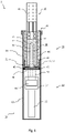
- Fig.1 schematically illustrates an aerosol-generating system 1 according to a first embodiment of the present invention that is configured to electrically heat an aerosol-forming substrate 91 such as to generate an aerosol.
- the system 1 comprises two components: an aerosol-generating article 90 including the aerosol-forming substrate 91 to be heated, and an aerosol-generating device 10 for use with the article 90 which comprises a receiving cavity 20 for receiving the article 90, and an electrical heating device 30 that is configured to heat the aerosol-forming substrate 91 within the article 90 when being inserted into the receiving cavity 20.
- the device 10 comprises a substantially rod-shaped device body formed by a substantially cylindrical device housing 11.
- the device 10 comprises a power supply 16, for example a lithium ion battery, as well as an electric circuitry 17 including a controller 18 for controlling operation of the device 10, in particular for controlling substrate heating.
- the device 10 comprises the receiving cavity 20.
- the receiving cavity 20 is open-ended at the proximal end 12 of device 10, thus allowing the article 90 to be readily inserted into the receiving cavity 20.
- the device 10 comprises a separating wall 40 that is arranged within the device housing 11.
- the separating wall 40 sustainably separates the receiving cavity 20 in the proximal portion 14 of the device 10 from the electronic parts in the distal portion 13 of the device 10.
- the separating wall 40 also serves as bushing configured to hold and pass through parts of the electrical heating device 30.
- the separating wall 40 is made of an electrically insulating material.
- the material of the separating wall 40 is also thermally insulating such as to prevent heat transfer from the receiving cavity 20 to the electronic parts in the distal portion 13 of the device 10.
- the separating wall 40 may be, for example, made of a thermally insulating plastic material, such as PEEK (polyether ether ketone).
- the device 10 further comprises sealing means 45, such as a gasket, which are arranged along the perimeter of the separating wall 40.
- the heating device 30 is a resistive heating device.
- the heating device 30 comprises a heating blade 31 comprising a metallic core sandwiched between two ceramic cover members.
- the blade is mounted to the separating wall 40 and thus fixedly arranged within the device housing 11. From the separating wall 40, the blade 31 extends into the receiving cavity 20, substantially along a center axis of the receiving cavity 20.
- a tapered proximal tip portion 33 at the proximal end of the heating blade 31 faces towards to opening of the cavity 20 at the proximal end 12 of the device 10.
- the heating blade 31 penetrates into the aerosol-forming substrate 91 in the distal tip end portion of the article 90.
- the outer surface of at least one cover member is coated with a metal track 32, for example made of platinum, serving as resistive heating element which is operatively coupled to the power supply 16 and the controller 17 for powering and controlling the resistive heating process.
- a metal track 32 for example made of platinum, serving as resistive heating element which is operatively coupled to the power supply 16 and the controller 17 for powering and controlling the resistive heating process.
- the aerosol-generating device 10 further comprises an extractor 60 - for example an extractor as described in WO 2013/076098 A2 - which is arranged within the receiving cavity 20 and configured to facilitate extraction of the article 90 from the heating blade 31.
- an extractor 60 - for example an extractor as described in WO 2013/076098 A2 - which is arranged within the receiving cavity 20 and configured to facilitate extraction of the article 90 from the heating blade 31.
- Fig. 2 illustrates the aerosol-generating article 90 according to Fig. 1 in more detail.
- the article 90 substantially has a rod shape resembling the shape of a conventional cigarette.
- the article 90 comprises four elements arranged in coaxial alignment: an aerosol-forming substrate 91 at a proximal end 98 of the article 90, a support element 92 having a central air passage 93, an aerosol-cooling element 94, and a filter plug 95 at a distal end 99 of the article 90 which serves as a mouthpiece.
- the aerosol-forming substrate 91 may include, for example, a crimped sheet of homogenized tobacco material including glycerin as an aerosol-former.
- the support element 92 comprises a hollow core forming a central air passage 93.
- the filter plug 95 may, for example, include cellulose acetate fibers. All four elements are substantially cylindrical elements, having substantially the same diameter. The four elements are arranged sequentially and circumscribed by an outer wrapper 96 made of cigarette paper such as to form a cylindrical rod. Further details of this specific aerosol-generating article, in particular of the four elements, are disclosed in WO 2015/176898 A1 .
- the article according to the present invention includes an indicator material 97 used for article recognition, that is, for identifying the genuineness of the article and for preventing usage of non-compatible or counterfeit articles.
- the metallic indicator material 97 is a thin film made of aluminum that is applied to the inner surface of the paper wrapper 96.
- the wrapper 96 may also be considered as an aluminized paper wrapper.
- the aerosol-generating device 10 comprises a sensing circuitry 50 including a field generator 52 in the form an induction coil 51.
- the sensing circuitry 50 is configured to detect the presence of the indicator material 97 in the aerosol-generating article 90 when being positioned close to the induction coil 51 upon insertion of the article into the receiving cavity 20.
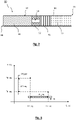
- the sensing circuitry 50 is configured to measure both, a change of the equivalent inductance ⁇ L_eq as well as a change of the equivalent resistance ⁇ R_eq of the induction coil 50 induced or caused by the indicator material 97 upon insertion of the aerosol-generating article 90 into the receiving cavity 20.
- the sensing circuitry 50 may include an oscillator circuitry for measuring both parameters.
- the induction coil 50 - as part of the sensing circuitry 50 - has an equivalent inductance L1_eq which decrease to a lower value L2_eq upon insertion of the aerosol-generating article 90 into the receiving cavity 20.
- This decrease is due to the specific magnetic permeability of the indicator material 97 changing the effective magnetic permeability within a space volume proximate the conductive coil 51.
- the induction coil 50 experiences an increase of the equivalent resistance from R1_eq upon insertion of the aerosol-generating article 90 into the receiving cavity 20. This increase is due to the specific resistivity of the indicator material 97 which represents a resistive load applied to the induction coil 51.
- the induction coil 51 preferably is part of an oscillator circuitry 50.
- the Q factor (quality factor) of the sensing circuitry is reduced. This causes a measurable voltage and current increase in the sensing circuitry such as to compensate for increased losses in the reactive load.
- the sensing circuitry 50 is operatively coupled with the controller 17.
- the sensing circuitry 50 is even part of the controller 17.
- the controller is configured to control operation of the heating device 30 based on a comparison of the measured change of the equivalent inductance and equivalent resistance with one or more predetermined values of change of the equivalent inductance and equivalent resistance.
- operation of the heating device 30 is activated by the controller 17 only in case both measured parameters ⁇ L_eq and ⁇ R_eq coincidentally correspond to the respective predetermined values, or at least are coincidently within a respective pre-defined range of acceptability ⁇ L_tol and ⁇ R_tol around the predetermined values.
- the induction coil 51 is arranged in a distal end portion 21 of the receiving cavity 20 within the device housing 11.
- the induction coil 51 is circumferentially arranged along an inner circumference of the receiving cavity 20 surrounding the distal end portion of the extractor 60.
- the induction coil 51 is a helical coil mounted to a coil support 55.
- the coil support 55 is a body of revolution resulting from rotation of a U-profile around an axis of rotation that is coaxial with the center axis of the receiving cavity 20. This configuration advantageously provides a good sensitivity and also a beneficial exploitation of available space within the device housing 11.
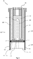
- Fig. 4 schematically illustrates an embodiment (detail only) of an aerosol-generating system 101 according to the present invention which is covered by the claims.
- the system 101 shown in Fig. 4 is very similar to the system 1 shown in Fig. 1 with regard to both, the aerosol-generating articles 90, 190 and the aerosol-generating devices 10, 110.
- the aerosol-generating articles 90, 190 are even identical. Therefore, like or identical features are denoted with the same reference numerals as in Fig. 1 , incremented by 100.
- the device 110 according to Fig. 4 does not comprise an induction coil within the receiving cavity.
- the induction coil 151 is arranged within a circumferential recess 141 peripherally extending along the outer circumference of the separating wall 140.
- this configuration allows the induction coil 151 to be sunk-in the recess and also to be securely sealed by the sealing means 145.
- arrangement of the induction coil 151 in a recess 141 of the separating wall 140 proves to be minimal invasive.
- the induction coil 151 is a helical coil having three turns and four layers.
- Fig. 5 and Fig. 6 show another arrangement of an induction coil which is not covered by the claims.
- the system comprises a coil support 255 which is configured to form a part of the wall the device housing that is to be laterally arranged next to the receiving cavity.
- the coil support 255 may be an inlet insertable into a corresponding opening of the device housing about the receiving cavity.
- the coil support 255 comprises a circumferential recess 259 for receiving the induction coil (not shown) such that an axis N - being normal to a plane defined by the windings of the induction coil - is orthogonal to a center axis of the cavity when the coil support 255 is mounted in the device.
- the induction coil is arranged within a portion of the wall of the device housing which surrounds or forms the receiving cavity. In this configuration, the induction coil only extends along a portion of the circumference of the receiving cavity and along a portion of the axial length extension of the receiving cavity.
Description
- The present invention relates to an electrically heated aerosol-generating device for use with an aerosol-generating article comprising means for article identification.
- Aerosol-generating systems based on electrically heating aerosol-forming substrates are generally known from prior art. Typically, these systems comprise two components: an aerosol-generating article including the aerosol-forming substrate to be heated, and an aerosol-generating device, wherein the device comprises a receiving cavity for receiving the article and an electrical heater, for example a resistive or an inductive heater, for heating the substrate within the article when the article is inserted into the receiving cavity. Such a system is known, for example, from
WO 99/20940 A1 - Typically, each electrically heated aerosol-generating device is designed for use with a specific type of an aerosol-generating article. This is due to the unique design of each aerosol-generating system that is defined by the specific type of substrate and its specific requirements for a well-controlled heating process. Otherwise, using an article with an aerosol-generating device which the article is not explicitly designed for may provide a different smoking experience for the user. In particular, using non-suitable articles may lead to overheating of the aerosol-forming substrate, thus causing an undesired combustion of the substrate. Even more, using articles which are non-compatible with a specific type of device may also damage the system.
- Though there are aerosol-generating systems - such as described, for example, in
WO 99/20940 A1 - Therefore, it would be desirable to have an aerosol-generating device for use with an aerosol-generating article, including improved means for article identification, in particular which provide increased difficulty to use non-compatible or counterfeit articles with the device.
- According to the invention there is provided an electrically heating aerosol-generating device for use with an aerosol-generating article, wherein the article includes an aerosol-forming substrate to be heated by the device. The device comprises a device housing including a receiving cavity within a proximal portion of the device for receiving at least a portion of the aerosol-generating article. The device further comprises at least one electrical heating device for heating an aerosol-forming substrate within the article when the article is received in the receiving cavity. The device also comprises a separating wall arranged adjacent to a distal end portion of the receiving cavity. The separating wall separates the receiving cavity within the proximal portion of the device from a distal portion of the device. Furthermore, the device comprises a sensing circuitry comprising a field generator. The sensing circuitry is configured to measure a change of at least one property of the field generator caused by the presence of an indicator arranged at or within the article when the article is received in the receiving cavity. According to the invention, the field generator is arranged adjacent to a distal end portion of the receiving cavity opposite to a proximal end portion of the receiving cavity within the separating wall or circumferentially around a perimeter or outer circumference of the separating wall.
- According to the invention it has been recognized that for many aerosol-generating devices known from prior art fault article detection is caused by disadvantageous arrangement of the identification means within the device. For example, in case the identification means are arranged about the entrance of the receiving cavity - which typically is located at the very proximal end of the device - article identification is likely to be susceptible to external influences, such as stray electromagnetic fields originating from parasitic field source in the surroundings of the device. This is particularly true for identification means based on electromagnetic induction. These may be, for example, identification means including induction coils configured to measure a change of an inductance caused by the presence of an inductive indicator within the article when the article is received in the receiving cavity. Using such means, parasitic electromagnetic fields may cause adverse induction effects in the induction coil causing article identification, even of suitable articles, to fail. As to this, article identification becomes less reliable the more the induction coil is exposed to such parasitic field sources.
- For this reason, the field generator according to the present invention is arranged adjacent to a distal end portion of the receiving cavity opposite to a proximal end portion of the receiving cavity. Advantageously, this arrangement provides sufficient shielding of the field generator from stray electromagnetic fields by the device itself. Accordingly, a disturbance of the field generated by the field generator when the article is introduced into the receiving cavity occurs in a well-shielded area under stable, that is, reproducible electromagnetic conditions.
- As a result, the aerosol-generating device according to the present invention allows for article identification that is significantly improved as compared to other devices known from prior art.
- In general, the field generator may be of any type and may have any configuration, shape and arrangement within the device housing suitable to sense the presence of the indicator arranged at or within the article when the article is introduced into the receiving cavity. Preferably, the field generator is arranged about a distal end of the receiving cavity.
- As used herein, the term "field generator" refers to an apparatus which is able to act as a source for a field, that is, the field generator may be configured to generate a field. Accordingly, the field generator may also be denoted as field source. The field may be an electrical field, a magnetic field, or an electromagnetic field. The field generator may comprise, for example, an induction coil, an antenna, or a magnet, in particular an electromagnet or a permanent magnet.
- The field generator is preferably an induction coil. Where this is the case, the induction coil may be a helical coil or a flat spiral coil, in particular a pancake coil or a flat curved spiral coil. Use of a flat spiral coil allows for compact design that is robust and inexpensive to manufacture. Use of a helical induction coil advantageously provides a substantially homogeneous field configuration in the interior of the coil. As used herein a "flat spiral coil" means a coil that is a generally planar coil, wherein the axis of winding of the coil is normal to the surface in which the coil lies. The flat spiral induction can have any desired shape within the plane of the coil. For example, the flat spiral coil may have a circular shape or may have a generally oblong or rectangular shape. However, the term "flat spiral coil" as used herein covers both, coils that are planar as well as flat spiral coils that are shaped to conform to a curved surface. For example, the induction coil may be a "curved" planar coil arranged at the circumference of a preferably cylindrical coil support, for example ferrite core. Furthermore, the flat spiral coil may comprise for example two layers of a four-turn flat spiral coil or a single layer of four-turn flat spiral coil. In order to prevent deposits on the induction coil and/or possible corrosion, the induction coil may comprise a protective cover or layer.
- The indicator presence of the indicator near to the field generator causes a disturbance in the field generated by the field generator. The disturbance in the field affects the field generator which leads to a change of the at least one property of the field generator. The change of the property may be observed by measuring a change in a parameter of the field generator. The parameter may be measured either directly or indirectly. The presence of the indicator, and therefore the article, may be determined by measuring the parameter and observing that the parameter has a different value in the presence of the indicator compared to the value in the absence of the indicator.
- The disturbance in the field generated by the field generator caused by the presence of the indicator may be due to an interaction between the field and the indicator.
- The indicator within the aerosol-generating article may have a specific magnetic permeability and a specific electrical resistivity. That is, the indicator may include a material having a specific magnetic permeability and a specific electrical resistivity. Preferably, the indicator comprises an electrically conductive material. For example, the indicator may comprise a metallic material. The metallic material may be, for example, one of aluminum, nickel, iron, or alloys thereof, for example, carbon steel or ferritic stainless steel. Aluminum has an electrical resistivity of about 2.65x10E-08 Ohm-meter, measured at room temperature (20°C), and a magnetic permeability of about 1.256×10E-06 Henry per meter. Likewise, ferritic stainless steel has an electrical resistivity of about 6.9×10E-07 Ohm-meter, measured at room temperature (20°C), and a magnetic permeability in a range of 1.26x10E-03 Henry per meter to 2.26x10E-03 Henry per meter.
- The at least one property of the field generator may be any property which has an associated parameter which has a different value in the presence of the indicator compared to the value in the absence of the indicator. For example, the at least one property may be current, voltage, resistance, frequency, phase shift, flux, and inductance of the field generator. Preferably the property is the inductance of the field generator.
- The indicator may be an inductive indicator.
- Inductance, generally speaking, includes the property of an electric circuit to be susceptible to exterior electromagnetic influences. As used herein, the term "inductance" as measured by the sensing circuitry refers to the imaginary part of a complex impedance defined as the ratio of the supplied AC voltage to the measured AC current.
- According to a non-claimed aspect, the field generator may be circumferentially arranged along an inner circumference of the receiving cavity, preferably along an inner circumference of a distal end portion of the receiving cavity, within the device housing. This configuration advantageously provides good sensitivity and also a beneficial exploitation of available space within the device housing, while still providing sufficient shielding of the field generator from stray electromagnetic fields. In this particular configuration, the field generator preferably is a helical coil or a curved planner coil arranged at the inner circumference of the receiving cavity, in particular at the inner circumference of a distal end portion of the receiving cavity.
- Additionally, the field generator may be mounted to a field generator support. For example the field generator support may be a coil support where the field generator is an induction coil. According to a non-claimed aspect, the field generator support may be circumferentially arranged along an inner circumference of the receiving cavity, in particular an inner circumference of a distal end portion of the receiving cavity. Usage of such a field generator support advantageously facilitates mounting of the field generator within the receiving cavity.
- Preferably, the field generator support is ring-shaped. For example, the field generator support may be a body of revolution resulting from rotation of a C- or U-profile around an axis of rotation. Preferably, the axis of rotation is coaxially with a center axis of the receiving cavity.
- The field generator support may comprise or consist of a ferrite (ferritic metal), plastics or a ceramic. Furthermore, the field generator support may be sunk-in or embedded in a bottom portion of the receiving cavity. The bottom portion is within at the distal end portion of the receiving cavity, opposite to a proximal open end of the receiving cavity at the proximal end of the aerosol-generating device.
- As mentioned above, the device comprises a separating wall arranged adjacent to a distal end portion (or bottom portion) of the receiving cavity. The separating wall separates a proximal portion of the device from a distal portion of the device, wherein the proximal portion includes the receiving cavity. The separating wall may have a rectangular cross-section or an oval cross-section or circular cross-section as seen in a direction along a center axis of the receiving cavity or along an overall length extension of the device. Preferably, the cross-section of the separating wall corresponds to the shape of the cross-section of the receiving cavity or to an overall cross-section of the heating device.
- Preferably, the separating wall sealingly separates the receiving cavity from the distal portion of the device. For this, the device may comprise sealing means, such as a gasket, in particular an O-ring, arranged along the perimeter or outer circumference of the separating wall. Preferably, the separating wall may be a bushing (electrical bushing), that is, an insulating member allowing to hold or pass through parts of an electrical conductor, for example, parts of the electrical heating device.
- According to a first alternative of the claimed invention, the field generator, for example an induction coil, is circumferentially arranged along an outer circumference or periphery of the separating wall. This configuration corresponds to an arrangement of the field generator adjacent to a distal end portion of the receiving cavity opposite to a proximal end portion of the receiving cavity.
- As to this, the field generator may be arranged (located) at a peripheral side of the separating wall which faces in a radial outward direction with regard to a center axis of the receiving cavity or an overall length extension of the device. Likewise, the field generator may be arranged (located) peripherally at a front side of the separating walls facing towards the proximal portion of the device, that is, towards the receiving cavity. Alternatively, the field generator may be arranged (located) peripherally at a rear side of the separating wall facing towards the distal portion of the device. These configurations prove advantageous with regard to a very compact design of the device.
- Even more preferably, the separating wall may comprise a circumferential recess, for example a circumferential groove, peripherally extending along its outer circumference. Advantageously, the field generator, for example an induction coil, may be arranged in this recess. Accordingly, this configuration allows the field generator to be sunk-in the recess and thus to be sealed. Also, this arrangement of the field generator within a recess is minimal invasive. As described above with regard to the positioning of the field generator, the recess may be arranged (located) at a peripheral side of the separating wall. This peripheral recess preferably is open in a radial outward direction with regard to a center axis of the receiving cavity or an overall length extension of the device. Alternatively, the recess may be arranged peripherally at a front side or rear side of the separating wall. In this configuration, the recess preferably is open in an axial direction with regard to center axis of the receiving cavity or an overall length extension of the device, that is, open either towards the proximal portion of the device, in particular the receiving cavity, or towards the distal portion of the device. The recess may have rectangular cross-section or a curved, in particular semi-oval or semi-circular cross-section. In this configuration, the field generator preferably is a helical induction coil having one or more turns and one or more layers.
- According to a second alternative of the claimed invention, the field generator is arranged within the separating wall, in particular integrated within the separating wall. Advantageously, this configuration also allows the field generator to be sealed off and thus protected from smoke and dust originating from the heating process within the receiving cavity. In this configuration, the field generator preferably is a flat pancake coil.
- According to another non-claimed aspect, the field generator may be arranged within a portion of a wall of the device housing, preferably within a portion of the wall of the device housing which surrounds or even forms the receiving cavity. This configuration also corresponds to an arrangement of the field generator adjacent to the receiving cavity, in particular to a distal end portion of the receiving cavity opposite to a proximal end portion of the receiving cavity.
- Preferably, the field generator may be arranged within a portion of a wall of the device housing such that an axis being normal to a plane defined by a winding of the field generator, for example of an induction coil is orthogonal to a center axis of the receiving cavity.
- The portion of the wall including the field generator preferably is confined in size. In particular, the field generator and, thus, the portion of the wall including the field generator only extends along a portion of the circumference of the receiving cavity and along a portion of the axial length extension of the receiving cavity.
- In this configuration, the field generator preferably is mounted to a field generator support which forms a part of the wall the device housing. In particular, the field generator support is laterally arranged with regard to the receiving cavity. For example, the field generator support may be an inlet inserted into a corresponding opening of the device housing. The field generator support may be configured such that an axis - being normal to a plane defined by the windings of the induction coil - is orthogonal to a center axis of the cavity.
- According to a further aspect of the invention, the device may comprise a controller which is operatively coupled with the sensing circuitry. The controller may be configured to control operation of the heating device based on a comparison of the measured change of the at least one property of the field generator, such as an inductance, with one or more predetermined values of change of the at least one property. Accordingly, operation of the heating device is activated by the controller only in case the measured of the at least one property corresponds to a predetermined value, or at least is within a respective pre-defined range of acceptability around the predetermined value. Otherwise, in case the at least one property is not verified, operation of the heating device is not activated. Thus, usage of non-compatible articles may be effectively prevented.
- Preferably, the sensing circuitry is further configured to measure a change of at least two properties, in particular two properties of the field generator caused by the presence of the indicator of the article when the article is received in the receiving cavity. For, the sensing circuitry may be configured to measure a change of an equivalent resistance as well as a change of an inductance of the field generator caused by the presence of the indicator of the article. As used herein, the term "equivalent resistance" refers to the real part of a complex impedance defined as the ratio of the supplied AC voltage to the measured AC current.
- In this configuration, the controller advantageously is configured to control operation of the heating device based on a comparison of the measured changes of the at least two properties of the field generator, for example of an inductance and a resistance of the field generator, with one or more predetermined values of change of the respective properties. As to this, it has been recognized that protection against undesired usage of non-compatible or counterfeit articles can be further increased by measuring and verifying the change of at least two properties of the field generator caused by the presence of the indicator (instead of one property only), that is, by measuring and verifying the effect of at least two parameters of the indicator on the field generator. Hence, operation of the heating device is activated by the controller only in case the respective changes of all of the at least two measured properties of the field generator are verified, that is, coincidentally correspond to the respective predetermined values, or at least are coincidently within a respective pre-defined range of acceptability around the predetermined values. Otherwise, in case at least one of the measured changes is not verified, operation of the heating device is not activated. The measured changes of the at least two properties of the field generator, for example the change of the equivalent inductance and the change of the equivalent resistance, thus form a set of properties, for example a property pair, to be coincidently verified.
- Preferably, the set of properties is unique to the use of a specific indicator with the article. In particular, the indicator may have a specific magnetic permeability and a specific electrical resistivity. Accordingly, the specific magnetic permeability and the specific electrical resistivity may form a unique parameter set such that there preferably is only one indicator material exhibiting the specific values of these parameters which exclusively is capable of inducing the predetermined changes of properties of the field generator, such as a predetermined change of its inductance and equivalent resistance. The predetermined changes of properties of the field generator may result from a calibration measurement and generally depend - in addition to the physical properties of the indicator, such as for example its magnetic permeability and electrical resistivity - from the geometric configuration of the indicator and the field generator as well as from the arrangement of the indicator relative to the field generator. Hence, apart from the geometry and relative arrangement of the indicator and the field generator, there is preferably a unique effect by the physical properties of the indicator to characteristic changes of specific properties of the field generator. For example, there may be a unique effect by the magnetic permeability and electrical resistivity of the indicator on the change of the inductance and the equivalent resistance of the field generator. Accordingly, there is preferably a unique relationship between a parameter set of physical properties of the indicator, such as the magnetic permeability and electrical resistivity, and a set of properties of the field generator, such as the change of inductance and change of equivalent resistance of the field generator. This unique relationship advantageously makes the identification or recognition of a genuine aerosol-generating article more reliable.
- As used herein, the term "aerosol-generating device" is used to describe an electrically operated device that is capable of interacting with at least one aerosol-forming substrate, in particular with an aerosol-forming substrate provided within an aerosol-generating article, such as to generate an aerosol by heating the substrate. Preferably, the aerosol-generating device is a puffing device for generating an aerosol that is directly inhalable by a user thorough the user's mouth. In particular, the aerosol-generating device is a hand-held aerosol-generating device.
- As used herein, the term "aerosol-generating article" refers to an article comprising at least one aerosol-forming substrate that, when heated, releases volatile compounds that can form an aerosol. Preferably, the aerosol-generating article is a heated aerosol-generating article. That is, an aerosol-generating article which comprises at least one aerosol-forming substrate that is intended to be heated rather than combusted in order to release volatile compounds that can form an aerosol. The aerosol-generating article may be a consumable, in particular a consumable to be discarded after a single use. For example, the article may be a cartridge including a liquid aerosol-forming substrate to be heated. Alternatively, the article may be a rod-shaped article, in particular a tobacco article, resembling conventional cigarettes.
- As used herein, the term "aerosol-forming substrate" relates to a substrate capable of releasing volatile compounds that can form an aerosol upon heating the aerosol-forming substrate. The aerosol-forming substrate is part of the aerosol-generating article. The aerosol-forming substrate may be a solid or a liquid aerosol-forming substrate. In both cases, the aerosol-forming substrate may comprise at least one of solid and liquid components. The aerosol-forming substrate may comprise a tobacco-containing material containing volatile tobacco flavor compounds, which are released from the substrate upon heating. Alternatively or additionally, the aerosol-forming substrate may comprise a non-tobacco material. The aerosol-forming substrate may further comprise an aerosol former. Examples of suitable aerosol formers are glycerine and propylene glycol. The aerosol-forming substrate may also comprise other additives and ingredients, such as nicotine or flavourants. The aerosol-forming substrate may also be a paste-like material, a sachet of porous material comprising aerosol-forming substrate, or, for example, loose tobacco mixed with a gelling agent or sticky agent, which could include a common aerosol former such as glycerine, and which is compressed or molded into a plug.
- The sensing circuitry including the field generator may be an oscillator circuitry.
- The electrical heating device preferably is a resistive heating device comprising a resistive heating element. The resistive heating element heats up when electrical current is passed through due to its immanent ohm resistance or resistive load. The resistive heating element may comprise at least one of a resistive heating wire, a resistive heating track, a resistive heating grid or a resistive heating mesh. Preferably, the heating device comprises a heating blade fixedly arranged within the receiving cavity, extending substantially along a center axis of the receiving cavity. The blade may comprise a tapered proximal tip portion at its proximal end facing towards to an opening of the receiving cavity at a proximal end of the device. Thus, upon inserting the article into the receiving cavity, the heating blade may readily penetrate into the aerosol-forming substrate of the article. For heating the substrate, at least one side of the heating blade may be coated with a metal track, for example made of platinum, serving as resistive heating element. Thus, when passing a driving current through the metal track the heating blade heats causing volatile compounds in the aerosol-forming substrate to be heated and released such as to form an aerosol.
- The controller of the aerosol-generating device used to control the heating process may be an overall controller. In particular, the controller may be configured to control the temperature of the aerosol-forming substrate, in particular to adjust the temperature of the aerosol-forming substrate to a target temperature. As to this, the controller may be configured to regulate a supply of current to the heating device. Current may be supplied to the heating device continuously following activation of the system or may be supplied intermittently, such as on a puff by puff basis.
- The controller may comprise a microprocessor, for example a programmable microprocessor, a microcontroller, or an application specific integrated chip (ASIC) or other electronic circuitry capable of providing control. The controller may comprise further electronic components, such as at least one DC/AC inverter and/or power amplifiers, for example a Class-D or Class-E power amplifier.
- In particular, the controller may include the sensing circuitry. As to this, the controller may be configured to run and read out the sensing circuitry
- The aerosol-generating device advantageously comprises a power supply, preferably a battery such as a lithium iron phosphate battery. As an alternative, the power supply may be another form of charge storage device such as a capacitor. The power supply may require recharging and may have a capacity that allows for the storage of enough energy for one or more user experiences. For example, the power supply may have sufficient capacity to allow for the continuous generation of aerosol for a period of around six minutes or for a period that is a multiple of six minutes. In another example, the power supply may have sufficient capacity to allow for a predetermined number of puffs or discrete activations of the heating device. Preferably, the aerosol-generating device comprises at least one air inlet in fluid communication with the receiving cavity. Accordingly, the aerosol-generating system may comprise an air path extending from the at least one air inlet into the receiving cavity, and possibly further through the aerosol-forming substrate within the article and a mouthpiece into a user's mouth.
- For removing the aerosol-forming substrate or aerosol-generating article after having been spent, the aerosol-generating device may further comprise an extractor - for example as described in
WO 2013/076098 A2 - for extracting the aerosol-forming substrate or aerosol-generating article received in the aerosol-generating device. Where the field generator is arranged within a distal end portion of the receiving cavity opposite to a proximal end portion of the receiving cavity, in particular where the field generator is circumferentially arranged along an inner circumference of the receiving cavity, in particular where the field generator is mounted to a ring-shaped field generator support which is circumferentially arranged along an inner circumference of the receiving cavity, for example of a distal end portion of the receiving cavity, the field generator and the coil support may surround or may be arranged such as to surround the extractor, in particular a distal end portion of the extractor. - According to the invention, there is also provided an aerosol-generating system which comprises an electrically heated aerosol-generating device according to the invention and as described herein as well as an aerosol-generating article for use with the device.
- The aerosol-generating article comprises an aerosol-forming substrate to be heated by the device upon insertion of the article into the receiving cavity of the device. Furthermore, the article includes an indicator that is configured to cause a change of at least one, preferably of at least two properties of the field generator when the article is received in the receiving cavity, for example a change an inductance of the field generator and preferably also a change of an equivalent resistance.
- As mentioned above, the indicator may include a material having a specific magnetic permeability and a specific electrical resistivity. Preferably, the indicator includes a metallic indicator material. The metallic indicator material may be, for example, one of aluminum, nickel, iron, or alloys thereof, for example, carbon steel, or ferritic stainless steel. Aluminum has an electrical resistivity of about 2.65x10E-08 Ohm-meter, measured at room temperature (20°C), and a magnetic permeability of about 1.256×10E-06 Henry per meter. Likewise, ferritic stainless steel has an electrical resistivity of about 6.9x10E-07 Ohm-meter, measured at room temperature (20°C), and a magnetic permeability in a range of 1.26x10E-03 Henry per meter to 2.26×10E-03 Henry per meter.
- The indicator may have any shape and/or configuration. For example, the indicator may comprise at least one of a wire, a particle, a patch, a ring, a shred, a filament, and a strip of a material which causes a disturbance in a field generated by the field generator. Preferably, the indicator is arranged close to the outer surface of the article. For example, the indicator may be a sleeve or wrapper or envelop surrounding at least a portion of the aerosol-forming substrate.
- Preferably, the indicator is arranged at least within a distal portion of the article, opposite to a proximal portion of the article which preferably comprise a mouthpiece, in particular filter plug. Of course, the indicator may be arranged along the entire length extension of the article or exclusively within a distal portion of the article.
- In general, the article may have a substantially rod shape, preferably resembling the shape of conventional cigarettes.
- The article may comprise different portions, in particular an aerosol-forming substrate at a proximal end portion of the article, a support element having a central air passage, an aerosol-cooling element, and a filter plug at a distal end of the article which serves as a mouthpiece.
- The article may further comprise a wrapper surrounding at least a portion of the aerosol-forming substrate or surrounding the different portions mentioned above such as to keep them together and to maintain the desired cross-sectional shape of the article. Preferably, the wrapper forms at least a portion of the outer surface of the article. For example, the wrapper may be a paper wrapper, in particular a paper wrapper made of cigarette paper. Alternatively, the wrapper may be a foil, for example made of plastics. The wrapper may be fluid permeable such as to allow vaporized aerosol-forming substrate to be released from the article, or to allow air to be drawn into the article through its circumference. Furthermore, the wrapper may comprise at least one volatile substance to be activated and released from the wrapper upon heating. For example, the wrapper may be impregnated with a flavoring volatile substance.
- Preferably, the wrapper includes the indicator or the indicator is arranged at or attached to the wrapper. In particular, the indicator itself may be a wrapper attached to the wrapper which forms at least a portion of the outer surface of the article. Preferably, the indicator is arranged or attached to the inner surface of such a wrapper. For example, the indicator may comprise a sleeve including an indicator material, which surrounding at least a portion of the aerosol-forming substrate and or extends along at least a portion of the length extension of the article. Likewise, the indicator may comprise a thin film or foil made of an indicator material that is applied to at least a portion of the inner surface of a wrapper which forms at least a portion of the outer surface of the article. Preferably, the metallic indicator material is applied to the inner surface of the wrapper, for example paper wrapper, within a distal portion of the article. The indicator material may be metal, for example aluminum. In this configuration, the wrapper may be considered as a metallized wrapper, in particular as an aluminized wrapper.
- Furthermore, the indicator preferably forms a closed loop electrically conductive path around the circumference of the article. For example, the indicator may form a wrapper which fully circumscribes at least a portion of the article. Advantageously, this causes the measured changes of the inductance and resistance to be more pronounced and thus article identification to be more reliable. Advantageously, this also allows the disturbance in the field generated by the field generator caused by the indicator, and the corresponding change in the at least one property, to be independent of the axial rotational orientation of the article relative to the device.
- The invention will be further described, by way of example only, with reference to the accompanying drawings, in which:
- Fig. 1
- is a schematic illustration of an aerosol-generating system according to a non-claimed embodiment, comprising an aerosol-generating device and an aerosol-generating system;
- Fig. 2
- is a detailed illustration of the aerosol-generating article according to
Fig. 1 ; - Fig. 3
- is a diagram showing identification parameters measured by the aerosol-generating system according to the present invention;
- Fig. 4
- is a detailed schematic illustration of an aerosol-generating system according to an embodiment of the present invention which is covered by the claims;
- Figs. 5-6
- illustrate an exemplary embodiment of a coil support forming a part of a housing wall of aerosol-generating device according another, non-claimed embodiment.
-
Fig.1 schematically illustrates an aerosol-generatingsystem 1 according to a first embodiment of the present invention that is configured to electrically heat an aerosol-formingsubstrate 91 such as to generate an aerosol. Thesystem 1 comprises two components: an aerosol-generatingarticle 90 including the aerosol-formingsubstrate 91 to be heated, and an aerosol-generatingdevice 10 for use with thearticle 90 which comprises a receivingcavity 20 for receiving thearticle 90, and anelectrical heating device 30 that is configured to heat the aerosol-formingsubstrate 91 within thearticle 90 when being inserted into the receivingcavity 20. - As can be seen from
Fig. 1 , thedevice 10 comprises a substantially rod-shaped device body formed by a substantiallycylindrical device housing 11. Within adistal portion 13, thedevice 10 comprises apower supply 16, for example a lithium ion battery, as well as anelectric circuitry 17 including a controller 18 for controlling operation of thedevice 10, in particular for controlling substrate heating. Within aproximal portion 14 opposite to thedistal portion 13, thedevice 10 comprises the receivingcavity 20. The receivingcavity 20 is open-ended at theproximal end 12 ofdevice 10, thus allowing thearticle 90 to be readily inserted into the receivingcavity 20. - As can be further seen from
Fig. 1 , thedevice 10 comprises a separatingwall 40 that is arranged within thedevice housing 11. The separatingwall 40 sustainably separates the receivingcavity 20 in theproximal portion 14 of thedevice 10 from the electronic parts in thedistal portion 13 of thedevice 10. In the present embodiment, the separatingwall 40 also serves as bushing configured to hold and pass through parts of theelectrical heating device 30. As to this, the separatingwall 40 is made of an electrically insulating material. Preferably, the material of the separatingwall 40 is also thermally insulating such as to prevent heat transfer from the receivingcavity 20 to the electronic parts in thedistal portion 13 of thedevice 10. Accordingly, the separatingwall 40 may be, for example, made of a thermally insulating plastic material, such as PEEK (polyether ether ketone). - To ensure proper protection of the electronic parts in the
distal portion 13 of thedevice 10 from dust and humidity, thedevice 10 further comprises sealing means 45, such as a gasket, which are arranged along the perimeter of the separatingwall 40. - The
heating device 30 according to the present embodiment is a resistive heating device. With reference toFig. 1 , theheating device 30 comprises aheating blade 31 comprising a metallic core sandwiched between two ceramic cover members. The blade is mounted to the separatingwall 40 and thus fixedly arranged within thedevice housing 11. From the separatingwall 40, theblade 31 extends into the receivingcavity 20, substantially along a center axis of the receivingcavity 20. A taperedproximal tip portion 33 at the proximal end of theheating blade 31 faces towards to opening of thecavity 20 at theproximal end 12 of thedevice 10. Thus, upon inserting thearticle 90 into the receivingcavity 20, theheating blade 31 penetrates into the aerosol-formingsubstrate 91 in the distal tip end portion of thearticle 90. For heating the substrate, the outer surface of at least one cover member is coated with ametal track 32, for example made of platinum, serving as resistive heating element which is operatively coupled to thepower supply 16 and thecontroller 17 for powering and controlling the resistive heating process. Thus, when passing the driving current through themetal track 32 theheating blade 31 heats causing volatile compounds in the aerosol-formingsubstrate 91 to be heated and released such as to form an aerosol. - For removing the aerosol-generating
article 90 after having been spent, the aerosol-generatingdevice 10 further comprises an extractor 60 - for example an extractor as described inWO 2013/076098 A2 - which is arranged within the receivingcavity 20 and configured to facilitate extraction of thearticle 90 from theheating blade 31. -
Fig. 2 illustrates the aerosol-generatingarticle 90 according toFig. 1 in more detail. Thearticle 90 substantially has a rod shape resembling the shape of a conventional cigarette. Thearticle 90 comprises four elements arranged in coaxial alignment: an aerosol-formingsubstrate 91 at aproximal end 98 of thearticle 90, asupport element 92 having acentral air passage 93, an aerosol-coolingelement 94, and afilter plug 95 at adistal end 99 of thearticle 90 which serves as a mouthpiece. The aerosol-formingsubstrate 91 may include, for example, a crimped sheet of homogenized tobacco material including glycerin as an aerosol-former. Thesupport element 92 comprises a hollow core forming acentral air passage 93. The filter plug 95 may, for example, include cellulose acetate fibers. All four elements are substantially cylindrical elements, having substantially the same diameter. The four elements are arranged sequentially and circumscribed by anouter wrapper 96 made of cigarette paper such as to form a cylindrical rod. Further details of this specific aerosol-generating article, in particular of the four elements, are disclosed inWO 2015/176898 A1 . - Yet, in contrast to the article disclosed in
WO 2015/176898 A1 , the article according to the present invention includes anindicator material 97 used for article recognition, that is, for identifying the genuineness of the article and for preventing usage of non-compatible or counterfeit articles. In the present embodiment, themetallic indicator material 97 is a thin film made of aluminum that is applied to the inner surface of thepaper wrapper 96. Thus, thewrapper 96 may also be considered as an aluminized paper wrapper. - To identify the genuineness of an article and to preventing usage of non-compatible or counterfeit articles, the aerosol-generating
device 10 comprises asensing circuitry 50 including a field generator 52 in the form an induction coil 51. Thesensing circuitry 50 is configured to detect the presence of theindicator material 97 in the aerosol-generatingarticle 90 when being positioned close to the induction coil 51 upon insertion of the article into the receivingcavity 20. - According to the present invention, the
sensing circuitry 50 is configured to measure both, a change of the equivalent inductance ΔL_eq as well as a change of the equivalent resistance ΔR_eq of theinduction coil 50 induced or caused by theindicator material 97 upon insertion of the aerosol-generatingarticle 90 into the receivingcavity 20. Typically, thesensing circuitry 50 may include an oscillator circuitry for measuring both parameters. - As illustrated in
Fig. 3 , the induction coil 50 - as part of the sensing circuitry 50 - has an equivalent inductance L1_eq which decrease to a lower value L2_eq upon insertion of the aerosol-generatingarticle 90 into the receivingcavity 20. This decrease is due to the specific magnetic permeability of theindicator material 97 changing the effective magnetic permeability within a space volume proximate the conductive coil 51. Likewise, theinduction coil 50 experiences an increase of the equivalent resistance from R1_eq upon insertion of the aerosol-generatingarticle 90 into the receivingcavity 20. This increase is due to the specific resistivity of theindicator material 97 which represents a resistive load applied to the induction coil 51. As described above, the induction coil 51 preferably is part of anoscillator circuitry 50. When theresistive indicator material 97 is positioned proximate the induction coil 51, the Q factor (quality factor) of the sensing circuitry is reduced. This causes a measurable voltage and current increase in the sensing circuitry such as to compensate for increased losses in the reactive load. - According to the invention, the
sensing circuitry 50 is operatively coupled with thecontroller 17. In the present embodiment, thesensing circuitry 50 is even part of thecontroller 17. According to the invention, the controller is configured to control operation of theheating device 30 based on a comparison of the measured change of the equivalent inductance and equivalent resistance with one or more predetermined values of change of the equivalent inductance and equivalent resistance. In particular, operation of theheating device 30 is activated by thecontroller 17 only in case both measured parameters ΔL_eq and ΔR_eq coincidentally correspond to the respective predetermined values, or at least are coincidently within a respective pre-defined range of acceptability ΔL_tol and ΔR_tol around the predetermined values. Otherwise, in case at least one of the measured parameters ΔL_eq or ΔR_eq is not verified, operation of theheating device 30 is not activated. Both, the change of the equivalent inductance ΔL_eq and the change of the equivalent resistance ΔR_eq thus form a parameter pair to be verified that is unique to the use of aspecific indicator material 97 having a specific magnetic permeability and a specific electrical resistivity. - As illustrated in
Fig. 1 , which shows an arrangement of the field generator according to an embodiment not covered by the claims, the induction coil 51 is arranged in adistal end portion 21 of the receivingcavity 20 within thedevice housing 11. In particular, the induction coil 51 is circumferentially arranged along an inner circumference of the receivingcavity 20 surrounding the distal end portion of theextractor 60. The induction coil 51 is a helical coil mounted to acoil support 55. Thecoil support 55 is a body of revolution resulting from rotation of a U-profile around an axis of rotation that is coaxial with the center axis of the receivingcavity 20. This configuration advantageously provides a good sensitivity and also a beneficial exploitation of available space within thedevice housing 11. -
Fig. 4 schematically illustrates an embodiment (detail only) of an aerosol-generatingsystem 101 according to the present invention which is covered by the claims. Thesystem 101 shown inFig. 4 is very similar to thesystem 1 shown inFig. 1 with regard to both, the aerosol-generatingarticles devices articles Fig. 1 , incremented by 100. Yet, in contrast to the aerosol-generatingdevice 1 according toFig. 1 , thedevice 110 according toFig. 4 does not comprise an induction coil within the receiving cavity. Instead, the induction coil 151 is arranged within acircumferential recess 141 peripherally extending along the outer circumference of the separatingwall 140. Advantageously, this configuration allows the induction coil 151 to be sunk-in the recess and also to be securely sealed by the sealing means 145. In addition, arrangement of the induction coil 151 in arecess 141 of the separatingwall 140 proves to be minimal invasive. Here, the induction coil 151 is a helical coil having three turns and four layers. -
Fig. 5 and Fig. 6 show another arrangement of an induction coil which is not covered by the claims. In this configuration, the system comprises acoil support 255 which is configured to form a part of the wall the device housing that is to be laterally arranged next to the receiving cavity. In particular, thecoil support 255 may be an inlet insertable into a corresponding opening of the device housing about the receiving cavity. Thecoil support 255 comprises acircumferential recess 259 for receiving the induction coil (not shown) such that an axis N - being normal to a plane defined by the windings of the induction coil - is orthogonal to a center axis of the cavity when thecoil support 255 is mounted in the device. Thus, the induction coil is arranged within a portion of the wall of the device housing which surrounds or forms the receiving cavity. In this configuration, the induction coil only extends along a portion of the circumference of the receiving cavity and along a portion of the axial length extension of the receiving cavity.
Claims (8)
- An electrically heated aerosol-generating device (110) for use with an aerosol-generating article (190), wherein the device (110) comprises- a device housing (111) including a receiving cavity (120) within a proximal portion (114) of the device (110) for receiving at least a portion of the aerosol-generating article (190);- a sensing circuitry (150) comprising a field generator (152), wherein the sensing circuitry (150) is configured to measure a change of at least one property of the field generator (152) caused by the presence of an indicator arranged at or within the article (190) when the article (190) is received in the receiving cavity (120);- at least one electrical heating device (130) for heating an aerosol-forming substrate (191) within the article (190) when the article (190) is received in the receiving cavity (120);characterized in that the device (110) comprises a separating wall (140) arranged adjacent to a distal end portion of the receiving cavity (120) separating the receiving cavity (120) within the proximal portion (114) of the device (110) from a distal portion (113) of the device (110), wherein the field generator (152) is arranged adjacent to a distal end portion of the receiving cavity (120) opposite to a proximal end portion of the receiving cavity (120) within the separating wall (140) or circumferentially around a perimeter or outer circumference of the separating wall (140).
- The device (110) according to claim 1, wherein the separating wall (140) comprises a circumferential recess (151), and wherein the field generator (152) is arranged in the circumferential recess.
- The device (110) according to any one of the preceding claims, wherein the field generator (152) is an induction coil (151), in particular a helical coil, or flat spiral coil, in particular a pancake coil or a flat curved spiral coil.
- The device (110) according to any one of the preceding claims, wherein the at least one property of the field generator (152) is an inductance of the field generator (152).
- The device (110) according to any one of the preceding claims, further comprising a controller (117) operatively coupled with the sensing circuitry (150), wherein the controller (117) is configured to control operation of the heating device (130) based on a comparison of the measured change of the at least one property of the field generator (152) with one or more predetermined values of change of the at least one property of the field generator (152).
- An aerosol-generating system (101), comprising an electrically heated aerosol-generating device (110) according to any one of the preceding claims and an aerosol-generating article (190) for use with the device (110), wherein the aerosol-generating article (190) comprises- an aerosol-forming substrate (191); and- a wrapper surrounding at least a portion of the aerosol-forming substrate (191), wherein the wrapper includes an indicator having a specific magnetic permeability and a specific electrical resistivity.
- The system (101) according to claim 6, wherein the indicator comprises a thin film or foil made of an electrically conductive material that is applied to at least a portion of the inner surface of the wrapper.
- The system (101) according to any one of claims 6 or 7, wherein the indicator forms a closed loop electrically conductive path around the circumference of the article (190).
Applications Claiming Priority (2)
| Application Number | Priority Date | Filing Date | Title |
|---|---|---|---|
| EP18189545 | 2018-08-17 | ||
| PCT/EP2019/071994 WO2020035586A1 (en) | 2018-08-17 | 2019-08-16 | Aerosol-generating device for use with an aerosol-generating article comprising means for article identification |
Publications (2)
| Publication Number | Publication Date |
|---|---|
| EP3836810A1 EP3836810A1 (en) | 2021-06-23 |
| EP3836810B1 true EP3836810B1 (en) | 2022-10-05 |
Family
ID=63311818
Family Applications (1)
| Application Number | Title | Priority Date | Filing Date |
|---|---|---|---|
| EP19755616.0A Active EP3836810B1 (en) | 2018-08-17 | 2019-08-16 | Aerosol-generating device for use with an aerosol-generating article comprising means for article identification |
Country Status (6)
| Country | Link |
|---|---|
| US (1) | US20210315279A1 (en) |
| EP (1) | EP3836810B1 (en) |
| JP (1) | JP7407170B2 (en) |
| KR (1) | KR20210042982A (en) |
| CN (1) | CN112543598B (en) |
| WO (1) | WO2020035586A1 (en) |
Families Citing this family (5)
| Publication number | Priority date | Publication date | Assignee | Title |
|---|---|---|---|---|
| EP3836811B1 (en) * | 2018-08-17 | 2022-10-05 | Philip Morris Products S.A. | Aerosol-generating device for use with an aerosol-generating article comprising means for article identification |
| KR20210119965A (en) * | 2019-01-25 | 2021-10-06 | 필립모리스 프로덕츠 에스.에이. | Shisha Cartridge with Cap |
| KR102531112B1 (en) * | 2021-03-11 | 2023-05-10 | 주식회사 케이티앤지 | Aerosol generating device including flow path |
| CN113876047A (en) * | 2021-11-10 | 2022-01-04 | 深圳雷炎科技有限公司 | Atomizer authenticity verification circuit and method based on constant current source and electronic atomization device |
| CN113966879A (en) * | 2021-11-10 | 2022-01-25 | 深圳雷炎科技有限公司 | Atomizer authenticity verification circuit, verification method and electronic atomization device |
Family Cites Families (10)
| Publication number | Priority date | Publication date | Assignee | Title |
|---|---|---|---|---|
| US5902501A (en) * | 1997-10-20 | 1999-05-11 | Philip Morris Incorporated | Lighter actuation system |
| EP2201850A1 (en) * | 2008-12-24 | 2010-06-30 | Philip Morris Products S.A. | An article including identification information for use in an electrically heated smoking system |
| ES2589260T5 (en) | 2011-11-21 | 2022-07-15 | Philip Morris Products Sa | Extractor for an aerosol generating device |
| US10980273B2 (en) * | 2013-11-12 | 2021-04-20 | VMR Products, LLC | Vaporizer, charger and methods of use |
| IL279066B (en) * | 2013-12-03 | 2022-09-01 | Philip Morris Products Sa | Aerosol-generating article and electrically operated system incorporating a taggant |
| CN116649630A (en) | 2014-05-21 | 2023-08-29 | 菲利普莫里斯生产公司 | Aerosol-generating article with internal susceptor |
| JP6800961B2 (en) * | 2015-09-24 | 2020-12-16 | フィリップ・モーリス・プロダクツ・ソシエテ・アノニム | Aerosol generator with electrodes for measuring electrical load |
| US11291252B2 (en) * | 2015-12-18 | 2022-04-05 | Rai Strategic Holdings, Inc. | Proximity sensing for an aerosol delivery device |
| WO2017118553A1 (en) * | 2016-01-07 | 2017-07-13 | Philip Morris Products S.A. | Aerosol-generating device with sealed compartment |
| CN109640716B (en) * | 2016-08-31 | 2022-03-01 | 菲利普莫里斯生产公司 | Aerosol-generating device with inductor |
-
2019
- 2019-08-16 WO PCT/EP2019/071994 patent/WO2020035586A1/en active Search and Examination
- 2019-08-16 US US17/268,180 patent/US20210315279A1/en active Pending
- 2019-08-16 CN CN201980052715.2A patent/CN112543598B/en active Active
- 2019-08-16 EP EP19755616.0A patent/EP3836810B1/en active Active
- 2019-08-16 JP JP2021507782A patent/JP7407170B2/en active Active
- 2019-08-16 KR KR1020217007792A patent/KR20210042982A/en unknown
Also Published As
| Publication number | Publication date |
|---|---|
| EP3836810A1 (en) | 2021-06-23 |
| JP7407170B2 (en) | 2023-12-28 |
| CN112543598B (en) | 2024-01-12 |
| US20210315279A1 (en) | 2021-10-14 |
| CN112543598A (en) | 2021-03-23 |
| WO2020035586A1 (en) | 2020-02-20 |
| JP2021534743A (en) | 2021-12-16 |
| KR20210042982A (en) | 2021-04-20 |
Similar Documents
| Publication | Publication Date | Title |
|---|---|---|
| EP3836810B1 (en) | Aerosol-generating device for use with an aerosol-generating article comprising means for article identification | |
| EP3836811B1 (en) | Aerosol-generating device for use with an aerosol-generating article comprising means for article identification | |
| EP3855956B1 (en) | Inductive heating assembly for inductive heating of an aerosol-forming substrate | |
| EP3855953B1 (en) | Heating assembly and method for inductively heating an aerosol-forming substrate | |
| EP3855960B1 (en) | Susceptor assembly for inductively heating an aerosol-forming substrate | |
| JP7358483B2 (en) | Induction heated aerosol generator with susceptor assembly | |
| EP3855954B1 (en) | Inductively heatable aerosol-generating article comprising an aerosol-forming substrate and a susceptor assembly | |
| US20220225682A1 (en) | Aerosol provision device | |
| US20220395024A1 (en) | Inductive heater assembly with temperature sensor | |
| AU2020308605B2 (en) | Inductor | |
| RU2810037C2 (en) | Electrically heated device generating aerosol and system generating aerosol and containing such device | |
| RU2808818C2 (en) | Electrically heated device generating aerosol and system generating aerosol and containing such device | |
| US20240049796A1 (en) | Aerosol generating system | |
| US20240108071A1 (en) | Aerosol provision device | |
| US20220232896A1 (en) | Aerosol provision device | |
| CA3233859A1 (en) | Aerosol-generating device |
Legal Events
| Date | Code | Title | Description |
|---|---|---|---|
| STAA | Information on the status of an ep patent application or granted ep patent |
Free format text: STATUS: UNKNOWN |
|
| STAA | Information on the status of an ep patent application or granted ep patent |
Free format text: STATUS: THE INTERNATIONAL PUBLICATION HAS BEEN MADE |
|
| STAA | Information on the status of an ep patent application or granted ep patent |
Free format text: STATUS: THE INTERNATIONAL PUBLICATION HAS BEEN MADE |
|
| PUAI | Public reference made under article 153(3) epc to a published international application that has entered the european phase |
Free format text: ORIGINAL CODE: 0009012 |
|
| STAA | Information on the status of an ep patent application or granted ep patent |
Free format text: STATUS: REQUEST FOR EXAMINATION WAS MADE |
|
| 17P | Request for examination filed |
Effective date: 20210308 |
|
| AK | Designated contracting states |
Kind code of ref document: A1 Designated state(s): AL AT BE BG CH CY CZ DE DK EE ES FI FR GB GR HR HU IE IS IT LI LT LU LV MC MK MT NL NO PL PT RO RS SE SI SK SM TR |
|
| DAV | Request for validation of the european patent (deleted) | ||
| DAX | Request for extension of the european patent (deleted) | ||
| REG | Reference to a national code |
Ref country code: DE Ref legal event code: R079 Ref document number: 602019020309 Country of ref document: DE Free format text: PREVIOUS MAIN CLASS: A24F0047000000 Ipc: A24F0040510000 |
|
| RIC1 | Information provided on ipc code assigned before grant |
Ipc: A24F 40/51 20200101AFI20220211BHEP |
|
| GRAP | Despatch of communication of intention to grant a patent |
Free format text: ORIGINAL CODE: EPIDOSNIGR1 |
|
| STAA | Information on the status of an ep patent application or granted ep patent |
Free format text: STATUS: GRANT OF PATENT IS INTENDED |
|
| INTG | Intention to grant announced |
Effective date: 20220405 |
|
| GRAS | Grant fee paid |
Free format text: ORIGINAL CODE: EPIDOSNIGR3 |
|
| GRAA | (expected) grant |
Free format text: ORIGINAL CODE: 0009210 |
|
| STAA | Information on the status of an ep patent application or granted ep patent |
Free format text: STATUS: THE PATENT HAS BEEN GRANTED |
|
| AK | Designated contracting states |
Kind code of ref document: B1 Designated state(s): AL AT BE BG CH CY CZ DE DK EE ES FI FR GB GR HR HU IE IS IT LI LT LU LV MC MK MT NL NO PL PT RO RS SE SI SK SM TR |
|
| REG | Reference to a national code |
Ref country code: GB Ref legal event code: FG4D |
|
| REG | Reference to a national code |
Ref country code: CH Ref legal event code: EP |
|
| REG | Reference to a national code |
Ref country code: AT Ref legal event code: REF Ref document number: 1522195 Country of ref document: AT Kind code of ref document: T Effective date: 20221015 |
|
| REG | Reference to a national code |
Ref country code: DE Ref legal event code: R096 Ref document number: 602019020309 Country of ref document: DE |
|
| REG | Reference to a national code |
Ref country code: IE Ref legal event code: FG4D |
|
| REG | Reference to a national code |
Ref country code: NL Ref legal event code: FP |
|
| REG | Reference to a national code |
Ref country code: LT Ref legal event code: MG9D |
|
| REG | Reference to a national code |
Ref country code: AT Ref legal event code: MK05 Ref document number: 1522195 Country of ref document: AT Kind code of ref document: T Effective date: 20221005 |
|
| PG25 | Lapsed in a contracting state [announced via postgrant information from national office to epo] |
Ref country code: SE Free format text: LAPSE BECAUSE OF FAILURE TO SUBMIT A TRANSLATION OF THE DESCRIPTION OR TO PAY THE FEE WITHIN THE PRESCRIBED TIME-LIMIT Effective date: 20221005 Ref country code: PT Free format text: LAPSE BECAUSE OF FAILURE TO SUBMIT A TRANSLATION OF THE DESCRIPTION OR TO PAY THE FEE WITHIN THE PRESCRIBED TIME-LIMIT Effective date: 20230206 Ref country code: NO Free format text: LAPSE BECAUSE OF FAILURE TO SUBMIT A TRANSLATION OF THE DESCRIPTION OR TO PAY THE FEE WITHIN THE PRESCRIBED TIME-LIMIT Effective date: 20230105 Ref country code: LT Free format text: LAPSE BECAUSE OF FAILURE TO SUBMIT A TRANSLATION OF THE DESCRIPTION OR TO PAY THE FEE WITHIN THE PRESCRIBED TIME-LIMIT Effective date: 20221005 Ref country code: FI Free format text: LAPSE BECAUSE OF FAILURE TO SUBMIT A TRANSLATION OF THE DESCRIPTION OR TO PAY THE FEE WITHIN THE PRESCRIBED TIME-LIMIT Effective date: 20221005 Ref country code: ES Free format text: LAPSE BECAUSE OF FAILURE TO SUBMIT A TRANSLATION OF THE DESCRIPTION OR TO PAY THE FEE WITHIN THE PRESCRIBED TIME-LIMIT Effective date: 20221005 Ref country code: AT Free format text: LAPSE BECAUSE OF FAILURE TO SUBMIT A TRANSLATION OF THE DESCRIPTION OR TO PAY THE FEE WITHIN THE PRESCRIBED TIME-LIMIT Effective date: 20221005 |
|
| PG25 | Lapsed in a contracting state [announced via postgrant information from national office to epo] |
Ref country code: RS Free format text: LAPSE BECAUSE OF FAILURE TO SUBMIT A TRANSLATION OF THE DESCRIPTION OR TO PAY THE FEE WITHIN THE PRESCRIBED TIME-LIMIT Effective date: 20221005 Ref country code: PL Free format text: LAPSE BECAUSE OF FAILURE TO SUBMIT A TRANSLATION OF THE DESCRIPTION OR TO PAY THE FEE WITHIN THE PRESCRIBED TIME-LIMIT Effective date: 20221005 Ref country code: LV Free format text: LAPSE BECAUSE OF FAILURE TO SUBMIT A TRANSLATION OF THE DESCRIPTION OR TO PAY THE FEE WITHIN THE PRESCRIBED TIME-LIMIT Effective date: 20221005 Ref country code: IS Free format text: LAPSE BECAUSE OF FAILURE TO SUBMIT A TRANSLATION OF THE DESCRIPTION OR TO PAY THE FEE WITHIN THE PRESCRIBED TIME-LIMIT Effective date: 20230205 Ref country code: HR Free format text: LAPSE BECAUSE OF FAILURE TO SUBMIT A TRANSLATION OF THE DESCRIPTION OR TO PAY THE FEE WITHIN THE PRESCRIBED TIME-LIMIT Effective date: 20221005 Ref country code: GR Free format text: LAPSE BECAUSE OF FAILURE TO SUBMIT A TRANSLATION OF THE DESCRIPTION OR TO PAY THE FEE WITHIN THE PRESCRIBED TIME-LIMIT Effective date: 20230106 |
|
| REG | Reference to a national code |
Ref country code: DE Ref legal event code: R097 Ref document number: 602019020309 Country of ref document: DE |
|
| P01 | Opt-out of the competence of the unified patent court (upc) registered |
Effective date: 20230529 |
|
| PG25 | Lapsed in a contracting state [announced via postgrant information from national office to epo] |
Ref country code: SM Free format text: LAPSE BECAUSE OF FAILURE TO SUBMIT A TRANSLATION OF THE DESCRIPTION OR TO PAY THE FEE WITHIN THE PRESCRIBED TIME-LIMIT Effective date: 20221005 Ref country code: RO Free format text: LAPSE BECAUSE OF FAILURE TO SUBMIT A TRANSLATION OF THE DESCRIPTION OR TO PAY THE FEE WITHIN THE PRESCRIBED TIME-LIMIT Effective date: 20221005 Ref country code: EE Free format text: LAPSE BECAUSE OF FAILURE TO SUBMIT A TRANSLATION OF THE DESCRIPTION OR TO PAY THE FEE WITHIN THE PRESCRIBED TIME-LIMIT Effective date: 20221005 Ref country code: DK Free format text: LAPSE BECAUSE OF FAILURE TO SUBMIT A TRANSLATION OF THE DESCRIPTION OR TO PAY THE FEE WITHIN THE PRESCRIBED TIME-LIMIT Effective date: 20221005 Ref country code: CZ Free format text: LAPSE BECAUSE OF FAILURE TO SUBMIT A TRANSLATION OF THE DESCRIPTION OR TO PAY THE FEE WITHIN THE PRESCRIBED TIME-LIMIT Effective date: 20221005 |
|
| PLBE | No opposition filed within time limit |
Free format text: ORIGINAL CODE: 0009261 |
|
| STAA | Information on the status of an ep patent application or granted ep patent |
Free format text: STATUS: NO OPPOSITION FILED WITHIN TIME LIMIT |
|
| PG25 | Lapsed in a contracting state [announced via postgrant information from national office to epo] |
Ref country code: SK Free format text: LAPSE BECAUSE OF FAILURE TO SUBMIT A TRANSLATION OF THE DESCRIPTION OR TO PAY THE FEE WITHIN THE PRESCRIBED TIME-LIMIT Effective date: 20221005 Ref country code: AL Free format text: LAPSE BECAUSE OF FAILURE TO SUBMIT A TRANSLATION OF THE DESCRIPTION OR TO PAY THE FEE WITHIN THE PRESCRIBED TIME-LIMIT Effective date: 20221005 |
|
| 26N | No opposition filed |
Effective date: 20230706 |
|
| PGFP | Annual fee paid to national office [announced via postgrant information from national office to epo] |
Ref country code: NL Payment date: 20230821 Year of fee payment: 5 |
|
| PGFP | Annual fee paid to national office [announced via postgrant information from national office to epo] |
Ref country code: IT Payment date: 20230822 Year of fee payment: 5 Ref country code: GB Payment date: 20230822 Year of fee payment: 5 Ref country code: CH Payment date: 20230902 Year of fee payment: 5 |
|
| PG25 | Lapsed in a contracting state [announced via postgrant information from national office to epo] |
Ref country code: SI Free format text: LAPSE BECAUSE OF FAILURE TO SUBMIT A TRANSLATION OF THE DESCRIPTION OR TO PAY THE FEE WITHIN THE PRESCRIBED TIME-LIMIT Effective date: 20221005 |
|
| PGFP | Annual fee paid to national office [announced via postgrant information from national office to epo] |
Ref country code: FR Payment date: 20230828 Year of fee payment: 5 Ref country code: DE Payment date: 20230821 Year of fee payment: 5 |
|
| PG25 | Lapsed in a contracting state [announced via postgrant information from national office to epo] |
Ref country code: MC Free format text: LAPSE BECAUSE OF FAILURE TO SUBMIT A TRANSLATION OF THE DESCRIPTION OR TO PAY THE FEE WITHIN THE PRESCRIBED TIME-LIMIT Effective date: 20221005 |
|
| PG25 | Lapsed in a contracting state [announced via postgrant information from national office to epo] |
Ref country code: MC Free format text: LAPSE BECAUSE OF FAILURE TO SUBMIT A TRANSLATION OF THE DESCRIPTION OR TO PAY THE FEE WITHIN THE PRESCRIBED TIME-LIMIT Effective date: 20221005 |
|
| PG25 | Lapsed in a contracting state [announced via postgrant information from national office to epo] |
Ref country code: LU Free format text: LAPSE BECAUSE OF NON-PAYMENT OF DUE FEES Effective date: 20230816 |