EP3836767B1 - Electronics module for an electric tool - Google Patents
Electronics module for an electric tool Download PDFInfo
- Publication number
- EP3836767B1 EP3836767B1 EP20201258.9A EP20201258A EP3836767B1 EP 3836767 B1 EP3836767 B1 EP 3836767B1 EP 20201258 A EP20201258 A EP 20201258A EP 3836767 B1 EP3836767 B1 EP 3836767B1
- Authority
- EP
- European Patent Office
- Prior art keywords
- shells
- electronic
- electronic components
- circuit board
- electronic module
- Prior art date
- Legal status (The legal status is an assumption and is not a legal conclusion. Google has not performed a legal analysis and makes no representation as to the accuracy of the status listed.)
- Active
Links
- 238000001816 cooling Methods 0.000 claims description 32
- 238000005266 casting Methods 0.000 claims description 16
- 239000003990 capacitor Substances 0.000 claims description 7
- HCHKCACWOHOZIP-UHFFFAOYSA-N Zinc Chemical compound [Zn] HCHKCACWOHOZIP-UHFFFAOYSA-N 0.000 claims description 3
- XAGFODPZIPBFFR-UHFFFAOYSA-N aluminium Chemical compound [Al] XAGFODPZIPBFFR-UHFFFAOYSA-N 0.000 claims description 3
- 229910052782 aluminium Inorganic materials 0.000 claims description 3
- 239000011701 zinc Substances 0.000 claims description 3
- 229910052725 zinc Inorganic materials 0.000 claims description 3
- MEKOFIRRDATTAG-UHFFFAOYSA-N 2,2,5,8-tetramethyl-3,4-dihydrochromen-6-ol Chemical compound C1CC(C)(C)OC2=C1C(C)=C(O)C=C2C MEKOFIRRDATTAG-UHFFFAOYSA-N 0.000 claims 4
- 239000004411 aluminium Substances 0.000 claims 1
- 150000001875 compounds Chemical class 0.000 description 12
- 230000017525 heat dissipation Effects 0.000 description 3
- 238000011109 contamination Methods 0.000 description 2
- 238000004382 potting Methods 0.000 description 2
- 238000010276 construction Methods 0.000 description 1
- 239000000463 material Substances 0.000 description 1
- 238000000034 method Methods 0.000 description 1
- 238000007789 sealing Methods 0.000 description 1
- 239000002918 waste heat Substances 0.000 description 1
Images
Classifications
-
- H—ELECTRICITY
- H05—ELECTRIC TECHNIQUES NOT OTHERWISE PROVIDED FOR
- H05K—PRINTED CIRCUITS; CASINGS OR CONSTRUCTIONAL DETAILS OF ELECTRIC APPARATUS; MANUFACTURE OF ASSEMBLAGES OF ELECTRICAL COMPONENTS
- H05K7/00—Constructional details common to different types of electric apparatus
- H05K7/20—Modifications to facilitate cooling, ventilating, or heating
- H05K7/2089—Modifications to facilitate cooling, ventilating, or heating for power electronics, e.g. for inverters for controlling motor
- H05K7/209—Heat transfer by conduction from internal heat source to heat radiating structure
-
- H—ELECTRICITY
- H05—ELECTRIC TECHNIQUES NOT OTHERWISE PROVIDED FOR
- H05K—PRINTED CIRCUITS; CASINGS OR CONSTRUCTIONAL DETAILS OF ELECTRIC APPARATUS; MANUFACTURE OF ASSEMBLAGES OF ELECTRICAL COMPONENTS
- H05K7/00—Constructional details common to different types of electric apparatus
- H05K7/20—Modifications to facilitate cooling, ventilating, or heating
- H05K7/2039—Modifications to facilitate cooling, ventilating, or heating characterised by the heat transfer by conduction from the heat generating element to a dissipating body
- H05K7/20509—Multiple-component heat spreaders; Multi-component heat-conducting support plates; Multi-component non-closed heat-conducting structures
-
- B—PERFORMING OPERATIONS; TRANSPORTING
- B25—HAND TOOLS; PORTABLE POWER-DRIVEN TOOLS; MANIPULATORS
- B25F—COMBINATION OR MULTI-PURPOSE TOOLS NOT OTHERWISE PROVIDED FOR; DETAILS OR COMPONENTS OF PORTABLE POWER-DRIVEN TOOLS NOT PARTICULARLY RELATED TO THE OPERATIONS PERFORMED AND NOT OTHERWISE PROVIDED FOR
- B25F5/00—Details or components of portable power-driven tools not particularly related to the operations performed and not otherwise provided for
- B25F5/008—Cooling means
Definitions
- the invention relates to an electronic module for a power tool, with a circuit board on which several electronic components are mounted, according to the type defined in more detail in the preamble of claim 1.
- the invention also relates to a power tool.
- a generic electronic module is from WO 2010/020459 A1 known.
- the DE 40 38 788 A1 describes an enclosure for containing electrical circuitry and dissipating excess heat generated by the electrical circuitry.
- the housing is enclosed on several sides and at the same time serves as a casting frame for the circuit, with a housing wall area also being a heat sink.
- a similar state of the art also shows EP 1 783 882 A2 .
- EP 2 873 494 A2 describes an angle grinder whose printed circuit board includes a heat sink which is arranged on an integrated power module.
- the DE 10 2007 063 310 A1 describes an electronic unit for use in a power tool with a cup element with a bottom part and side parts, a U-shaped cooling element with a cover part and leg parts and a printed circuit board, which is arranged in the cup element and is fixed to the cooling element via a fastening element.
- the U-shaped cooling element is placed on the cup element in such a way that an opening of the cup element opposite the base part is covered by the cover part of the cooling element, so that a section of the opening of the cup element remains uncovered.
- a power adapter with a housing is known, which is formed from a lower cover shell and an upper cover shell and an air passage extending across the bottom cover shell and an outlet opening in the top cover shell.
- a fundamental problem with such electronic modules is the dissipation of the heat generated by the electronic components.
- the solutions described above are sometimes able to dissipate a certain amount of heat, but often not to a sufficient extent.
- a further problem which the known constructions do not solve satisfactorily consists in the comparatively large space requirement of the cooling elements and the susceptibility of the electronic components to contamination.
- circuit board By arranging the circuit board within the trough-like receiving element, it is possible to completely encapsulate the circuit board with a casting compound or to pour it into the casting compound, which is also located inside the trough-like receiving element. In this way, the circuit board is very well protected against dirt and similar external influences.
- the cooling element is cast with the casting compound, so that the electronic components arranged inside the cooling element are also completely protected.
- the cooling element is not completely encapsulated.
- the cooling element By designing the cooling element from two half-shells, it is possible in a very simple manner to connect the electronic components to the cooling element and then mount them on the circuit board.
- a particularly practice-relevant embodiment of the invention can consist in the electronic components connected to at least one of the half-shells being electronic switching elements and/or rectifiers.
- a further embodiment of the invention can consist in at least one electronic component being connected to both half-shells and at least one capacitor being arranged between the electronic components connected to the half-shells. In this way, the at least one capacitor is also protected from external influences.
- the protection of the electronic components arranged within the two half-shells forming the casing can be further improved if the area in which the half-shells abut one another is cast with the casting compound.
- a particularly good sealing of the area where the half-shells abut one another results if the half-shells are each provided with chamfers in the area where they abut one another, with the chamfers of two half-shells forming a depression for receiving the casting compound.
- the electronic components are screwed to the half-shells. This enables the electronic components to be connected to the half-shells that form the cooling element in an equally simple and secure manner.
- the half-shells are designed as zinc die-cast components. A particularly good heat dissipation is achieved in this way.
- the half-shells in the form of die-cast aluminum components.
- a power tool with an electronic module according to the invention is specified in claim 10.
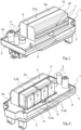
- figure 1 shows an electronic module 1 for a power tool, not shown in its entirety, such as an angle grinder.
- a power tool such as an angle grinder.
- the electronic module 1 described below is also suitable for other power tools.
- the electronic module 1 has a figure 1 circuit board 2, indicated only by a dashed line, on which a plurality of electronic components 3 are mounted. Furthermore, the electronics module 1 has a trough-like receiving element 4 for receiving the circuit board 2 and a cooling element 5 for cooling the electronic components 3 .
- the cooling element 5 is provided for absorbing the waste heat generated by the electronic components 3 and dissipating it to the environment. Since the cooling element 5 has a significantly larger surface area than the electronic components 3, a significantly higher amount of heat can be dissipated in this way.
- the circuit board is arranged within the trough-like receiving element 4 in such a way that an upper edge 4a of the trough-like receiving element 4 protrudes beyond the circuit board 2 .
- the circuit board 2 is arranged in a recessed manner in the trough-like receiving element 4 .
- the circuit board 2 is cast in the trough-like receiving element 4 with a casting compound 6 .
- the potting compound 6 is contained in the trough-like receiving element 4 up to such a height that the cooling element 5 is also embedded in the potting compound 6 . This results in the circuit board 2 being completely sealed, so that no more dirt can get into the area of the circuit board 2 . Materials known per se can be used for the casting compound 6 .
- the cooling element 5 is formed from two half-shells 5a and 5b lying against one another, which together form a casing 5c, within which the electronic components 3 are arranged.
- the cooling element 5 could in principle also be designed in one piece.
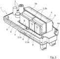
- FIG. 2 in each of which one of the half-shells 5a or 5b was omitted, the electronic components 3 can be seen in more detail.
- FIG 2 A total of four electronic components 3 embodied as electronic switching elements 3a and two electronic components 3b embodied as capacitors 3b can be seen.
- figure 3 1 shows two further electronic components 3 designed as electronic switching elements 3a and an electronic component 3 designed as a rectifier 3c.
- the power tool preferably has a brushless electric motor, for which the electronic components 3 mentioned are required.
- the arrangement of the capacitors 3b within the cooling element 5 means that they are additionally protected against external influences, even if they do not develop excessive heat.
- other embodiments, arrangements and numbers of the electronic components 3 are also conceivable.
- the electronic switching elements 3a and the rectifier 3c are screwed to the half-shells 5a and 5b.
- the half-shells 5a and 5b only have figure 1 and there also only partially recognizable threaded bores 7, which engage through through bores 8 in the electronic components 3 running screws, not shown.
- the two capacitors 3b are arranged with the rectifier 3c.
- the half-shells 5a and 5b of the cooling element 5 are preferably designed as zinc die-cast components or as aluminum die-cast components.
- the electronic components 3, in the present case the electronic switching elements 3a and the rectifier 3c, are screwed to the half-shells 5a and 5b before the two half-shells 5a and 5b are assembled, and then mounted on the circuit board 2. This results in the half-shells 5a and 5b being connected to the circuit board 2 via the electronic components 3, which can be soldered to the circuit board 2 or connected in some other way.
- the cooling element 5 does not touch the circuit board 2 directly.
- such an embodiment, in which the cooling element 5 bears against the circuit board 2 would be conceivable in principle.
- the area in which the half-shells 5a and 5b abut one another is also cast with the casting compound 6 .
- the half-shells 5a and 5b have respective chamfers 9 in the area in which they abut one another, the chamfers 9 being designed in such a way that they abut one another Contact of the two half-shells 5a and 5b form a recess 10 for receiving the casting compound 6.
Description
Die Erfindung betrifft ein Elektronikmodul für ein Elektrowerkzeug, mit einer Platine, auf der mehrere elektronische Bauelemente angebracht sind, nach der im Oberbegriff von Anspruch 1 näher definierten Art. Des Weiteren betrifft die Erfindung ein Elektrowerkzeug.The invention relates to an electronic module for a power tool, with a circuit board on which several electronic components are mounted, according to the type defined in more detail in the preamble of
Ein gattungsgemäßes Elektronikmodul ist aus der
Die
In der
Die
Aus der
Ein grundsätzliches Problem bei solchen Elektronikmodulen besteht in der Abführung der Wärme, welche von den elektronischen Bauelementen erzeugt wird. Die oben beschriebenen Lösungen sind teilweise in der Lage, eine bestimmte Wärmemenge abzuführen, häufig jedoch nicht in einem ausreichenden Umfang. Ein weiteres Problem, das die bekannten Konstruktionen nicht zufriedenstellend lösen, besteht in dem vergleichsweise großen Platzbedarf der Kühlelemente sowie der Verschmutzungsanfälligkeit der elektronischen Bauelemente.A fundamental problem with such electronic modules is the dissipation of the heat generated by the electronic components. The solutions described above are sometimes able to dissipate a certain amount of heat, but often not to a sufficient extent. A further problem which the known constructions do not solve satisfactorily consists in the comparatively large space requirement of the cooling elements and the susceptibility of the electronic components to contamination.
Es ist daher Aufgabe der vorliegenden Erfindung, ein Elektronikmodul für ein Elektrowerkzeug zu schaffen, das eine zuverlässige Wärmeabfuhr für die elektronischen Bauelemente und einen Schutz derselben vor Verschmutzung bietet.It is therefore the object of the present invention to create an electronics module for a power tool that offers reliable heat dissipation for the electronic components and protection of the same from contamination.
Erfindungsgemäß wird diese Aufgabe durch die in Anspruch 1 genannten Merkmale gelöst.According to the invention, this object is achieved by the features mentioned in
Durch die Anordnung der Platine innerhalb des wannenartigen Aufnahmeelements ist es möglich, die Platine vollständig mit einer Vergussmasse zu vergießen bzw. in die Vergussmasse einzugießen, die sich ebenfalls innerhalb des wannenartigen Aufnahmeelements befindet. Auf diese Weise ergibt sich ein sehr guter Schutz der Platine vor Verschmutzungen und ähnlichen äußeren Einflüssen.By arranging the circuit board within the trough-like receiving element, it is possible to completely encapsulate the circuit board with a casting compound or to pour it into the casting compound, which is also located inside the trough-like receiving element. In this way, the circuit board is very well protected against dirt and similar external influences.
Dabei ist erfindungsgemäß nicht nur die Platine, sondern auch das Kühlelement mit der Vergussmasse vergossen, sodass auch die innerhalb des Kühlelements angeordneten elektronischen Bauelemente vollständig geschützt sind. Im Gegensatz zu der Platine ist das Kühlelement allerdings nicht vollständig eingegossen.According to the invention, not only the circuit board but also the cooling element is cast with the casting compound, so that the electronic components arranged inside the cooling element are also completely protected. In contrast to the circuit board, however, the cooling element is not completely encapsulated.
Durch die Ausführung des Kühlelements aus zwei Halbschalen ist es auf sehr einfache Weise möglich, die elektronischen Bauelemente mit dem Kühlelement zu verbinden und anschließend auf der Platine zu montieren.By designing the cooling element from two half-shells, it is possible in a very simple manner to connect the electronic components to the cooling element and then mount them on the circuit board.
Eine besonders praxisrelevante Ausführungsform der Erfindung kann darin bestehen, dass die mit wenigstens einer der Halbschalen verbundenen elektronischen Bauelemente elektronische Schaltelemente und/oder Gleichrichter sind.A particularly practice-relevant embodiment of the invention can consist in the electronic components connected to at least one of the half-shells being electronic switching elements and/or rectifiers.
Obwohl Kondensatoren an sich nicht mittels eines zusätzlichen Kühlelements gekühlt werden müssen, kann eine weitere Ausgestaltung der Erfindung darin bestehen, dass mit beiden Halbschalen jeweils wenigstens ein elektronisches Bauelement verbunden ist, und dass zwischen den mit den Halbschalen verbundenen elektronischen Bauelementen wenigstens ein Kondensator angeordnet ist. Auf diese Weise ist der wenigstens ein Kondensator ebenfalls vor äußeren Einflüssen geschützt.Although capacitors do not have to be cooled by means of an additional cooling element, a further embodiment of the invention can consist in at least one electronic component being connected to both half-shells and at least one capacitor being arranged between the electronic components connected to the half-shells. In this way, the at least one capacitor is also protected from external influences.
Der Schutz der innerhalb der beiden die Umhüllung bildenden Halbschalen angeordneten elektronischen Bauelemente kann noch weiter verbessert werden, wenn der Bereich, in dem die Halbschalen aneinander anliegen, mit der Vergussmasse vergossen sind.The protection of the electronic components arranged within the two half-shells forming the casing can be further improved if the area in which the half-shells abut one another is cast with the casting compound.
Dabei ergibt sich eine besonders gute Abdichtung des Bereichs, an dem die Halbschalen aneinander anliegen, wenn die Halbschalen in dem Bereich, in dem sie aneinander anliegen, jeweils mit Fasen versehen sind, wobei die Fasen zweier Halbschalen eine Vertiefung zum Aufnehmen der Vergussmasse bilden.A particularly good sealing of the area where the half-shells abut one another results if the half-shells are each provided with chamfers in the area where they abut one another, with the chamfers of two half-shells forming a depression for receiving the casting compound.
In einer weiteren sehr vorteilhaften Ausführungsform der Erfindung kann vorgesehen sein, dass die elektronischen Bauelemente mit den Halbschalen verschraubt sind. Dies ermöglicht eine gleichermaßen einfache wie sichere Verbindung der elektronischen Bauelemente mit den das Kühlelement bildenden Halbschalen.In a further very advantageous embodiment of the invention it can be provided that the electronic components are screwed to the half-shells. This enables the electronic components to be connected to the half-shells that form the cooling element in an equally simple and secure manner.
Diese Verbindung kann besonders einfach in die Praxis umgesetzt werden, wenn die Halbschalen jeweilige Gewindebohrungen aufweisen, in welche durch Durchgangsbohrungen in den elektronischen Bauelementen verlaufende Schrauben eingreifen.This connection can be put into practice in a particularly simple manner if the half-shells have respective threaded bores in which screws running through through-holes in the electronic components engage.
Des Weiteren kann vorgesehen sein, dass die Halbschalen als Zinkdruckgussbauteile ausgebildet sind. Auf diese Weise wird eine besonders gute Wärmeabfuhr erreicht.Furthermore, it can be provided that the half-shells are designed as zinc die-cast components. A particularly good heat dissipation is achieved in this way.
Alternativ ist es zum Erreichen einer guten Wärmeabfuhr auch möglich, dass die Halbschalen als Aluminiumdruckgussbauteile ausgebildet sind.Alternatively, in order to achieve good heat dissipation, it is also possible for the half-shells to be in the form of die-cast aluminum components.
Ein Elektrowerkzeug mit einem erfindungsgemäßen Elektronikmodul ist in Anspruch 10 angegeben.A power tool with an electronic module according to the invention is specified in
Ergänzend sei darauf hingewiesen, dass Begriffe, wie "umfassend" "aufweisen" oder "mit" keine anderen Merkmale oder Schritte ausschließen. Ferner schließen Begriffe "ein" oder "das", die auf einer Einzahl von Schritten oder Merkmalen hinweisen, keine Mehrzahl von Merkmalen oder Schritten aus und umgekehrt.In addition, it should be pointed out that terms such as "comprising", "having" or "with" do not exclude any other features or steps. Furthermore, terms "a" or "the" indicating a singular number of features or features do not exclude a plurality of features or steps, and vice versa.
Weitere Merkmale und Vorteile der Erfindung ergeben sich aus der nachfolgenden Beschreibung eines Ausführungsbeispiels der Erfindung. Die Figuren zeigen mehrere Merkmale der Erfindung in Kombination miteinander. Selbstverständlich vermag der Fachmann diese jedoch auch losgelöst voneinander zu betrachten und gegebenenfalls zu weiteren sinnvollen Unterkombinationen zu kombinieren, ohne hierfür erfinderisch tätig werden zu müssen.Further features and advantages of the invention result from the following description of an exemplary embodiment of the invention. The figures show several features of the invention in combination with one another. Of course, the person skilled in the art can also consider these separately from one another and, if necessary, combine them to form further meaningful sub-combinations without having to be inventive.
Es zeigen schematisch:
Figur 1- eine perspektivische Ansicht eines erfindungsgemäßen Elektronikmoduls mit einem vollständig geschlossenen Kühlelement;
Figur 2- das Elektronikmodul aus
Figur 1 Figur 3- das Elektronikmodul aus
Figur 1
- figure 1
- a perspective view of an electronic module according to the invention with a completely closed cooling element;
- figure 2
- the electronics module
figure 1 , in which one of the half-shells has been removed; and - figure 3
- the electronics module
figure 1 , in which the other half-shell was removed.
Das Elektronikmodul 1 weist eine in
Die Platine ist derart innerhalb des wannenartigen Aufnahmeelements 4 angeordnet, dass ein oberer Rand 4a des wannenartigen Aufnahmeelements 4 die Platine 2 überragt. Mit anderen Worten, die Platine 2 ist vertieft in dem wannenartigen Aufnahmeelement 4 angeordnet. Des Weiteren ist die Platine 2 mit einer Vergussmasse 6 in dem wannenartigen Aufnahmeelement 4 eingegossen. Im vorliegenden Fall ist die Vergussmasse 6 bis zu einer solchen Höhe in dem wannenartigen Aufnahmeelement 4 enthalten, dass auch das Kühlelement 5 in die Vergussmasse 6 eingebettet ist. Dadurch ergibt sich eine vollkommene Abdichtung der Platine 2, so dass keinerlei Verschmutzung mehr in den Bereich der Platine 2 gelangen kann. Für die Vergussmasse 6 können an sich bekannte Materialien verwendet werden.The circuit board is arranged within the trough-like receiving
Das Kühlelement 5 ist im vorliegenden Fall aus zwei aneinander anliegenden Halbschalen 5a und 5b gebildet, die gemeinsam eine Umhüllung 5c bilden, innerhalb welcher die elektronischen Bauelemente 3 angeordnet sind. Die beiden Halbschalen 5a und 5b, die gemeinsam die Umhüllung 5c bilden, erzeugen zusammen mit der Vergussmasse 6 also einen komplett abgeschlossenen Raum. Durch die Ausführungsform des Kühlelements 5 mit den beiden Halbschalen 5a und 5b können die elektronischen Bauelemente 3 sehr einfach mit denselben verbunden werden. Statt der zweiteiligen Ausführung mit den beiden Halbschalen 5a und 5b könnte das Kühlelement 5 grundsätzlich auch einteilig ausgebildet sein.In the present case, the
In den
Durch die Anordnung der Kondensatoren 3b innerhalb des Kühlelements 5 sind diese zusätzlich gegen äußere Einflüsse geschützt, auch wenn sie keine übermäßige Wärmeentwicklung aufweisen. Selbstverständlich sind auch andere Ausführungsformen, Anordnungen und Anzahlen der elektronischen Bauelemente 3 denkbar.The arrangement of the capacitors 3b within the
Im vorliegenden Fall sind die elektronischen Schaltelemente 3a und der Gleichrichter 3c mit den Halbschalen 5a und 5b verschraubt. Hierzu weisen die Halbschalen 5a und 5b jeweilige nur in
Durch dieses Verschrauben liegen die elektronischen Bauelemente 3 unmittelbar an den Halbschalen 5a und 5b des Kühlelements 5 an und haben einen engen Kontakt zu denselben, so dass die im Betrieb von den elektronischen Bauelementen 3 erzeugte Wärme unmittelbar an das Kühlelement 5 abgegeben wird. Alternativ zu dem Verschrauben der elektronischen Bauelemente 3 mit dem Kühlelement 5 wäre es auch möglich, diese Bauteile mittels Klammern oder ähnlichem miteinander zu verbinden. Allerdings stellt das Verschrauben der elektronischen Bauelemente 3 mit den Halbschalen 5a und 5b eine sehr einfache und zuverlässige Vorgehensweise dar.As a result of this screwing, the
Um die Wärme aufnehmen und an die Umgebung abgeben zu können, sind die Halbschalen 5a und 5b des Kühlelements 5 vorzugsweise als Zinkdruckgussbauteile oder als Aluminiumdruckgussbauteile ausgebildet.In order to be able to absorb the heat and emit it to the environment, the half-
Die elektronischen Bauelemente 3, im vorliegenden Fall die elektronischen Schaltelemente 3a und der Gleichrichter 3c, werden vor der Montage der beiden Halbschalen 5a und 5b mit den Halbschalen 5a und 5b verschraubt und anschließend auf der Platine 2 montiert. Dadurch ergibt sich eine Verbindung der Halbschalen 5a und 5b mit der Platine 2 über die elektronischen Bauelemente 3, die mit der Platine 2 verlötet oder auf andere Art und Weise verbunden werden können. Im vorliegenden Fall berührt das Kühlelement 5 die Platine 2 somit nicht direkt. Eine solche Ausführungsform, bei der das Kühlelement 5 an der Platine 2 anliegt, wäre jedoch grundsätzlich denkbar.The
Zusätzlich zu dem oben beschriebenen Vergießen der Halbschalen 5a und 5b wird auch der Bereich, in dem die Halbschalen 5a und 5b aneinander anstoßen, mit der Vergussmasse 6 vergossen. Dies ist in den Figuren jedoch nicht dargestellt. Hierzu weisen die Halbschalen 5a und 5b in dem Bereich, in dem sie aneinander anliegen, jeweilige Fasen 9 auf, wobei die Fasen 9 so gestaltet sind, dass sie beim aneinander Anliegen der beiden Halbschalen 5a und 5b eine Vertiefung 10 zum Aufnehmen der Vergussmasse 6 bilden.In addition to the casting of the half-
Claims (10)
- Electronic module (1) for a power tool, having a printed circuit board (2) on which a plurality of electronic components (3) are mounted, having a trough-like receiving element (4) for receiving the printed circuit board (2) and having a cooling element (5) for cooling the electronic components (3), the circuit board (2) being arranged within the trough-like receiving element (4) in such a way that an upper edge (4a) of the trough-like receiving element (4) projects beyond the circuit board (2), the circuit board (2) being cast with a casting compound (6) in the trough-like receiving element (4),
characterized in that the cooling element (5) is embedded in the casting compound (6), and in that the cooling element (5) is formed from two half-shells (5a, 5b) which bear against one another, the electronic components (3) being connected to at least one of the half-shells (5a, 5b) and being arranged within an enclosure (5c) formed by the half-shells (5a, 5b). - Electronic module according to claim 1,
characterized in that the electronic components (3) connected to at least one of the half-shells (5a, 5b) are electronic switching elements (3a) and/or rectifiers (3c). - Electronic module according to claim 2,
characterized in that at least one electronic component (3) is connected to each of the two half-shells (5a, 5b), and in that at least one capacitor (3b) is arranged between the electronic components (3) connected to the half-shells (5a, 5b). - Electronic module according to claim 1, 2 or 3,
characterized in that the region in which the half-shells (5a, 5b) bear against one another is cast with the casting compound (6). - Electronic module according to claim 4,
characterized in that the half-shells (5a, 5b) are each provided with chamfers (9) in the region in which they bear against one another, the chamfers (9) of two half-shells (5a, 5b) forming a depression (10) for receiving the casting compound (6). - Electronic module according to one of claims 1 to 5,
characterized in that the electronic components (3) are screwed to the half-shells (5a, 5b). - Electronic module according to claim 6,
characterized in that the half-shells (5a,5b) have respective threaded holes (7) in which screws extending through through-holes (8) in the electronic components (3) engage. - Electronic module according to any one of claims 1 to 7,
characterized in that the half-shells (5a, 5b) are formed as zinc die-cast components. - Electronic module according to any one of claims 1 to 7,
characterized in that the half-shells (5a, 5b) are formed as aluminium die-cast components. - Power tool having an electronic module (1) according to one of the claims 1 to 9.
Applications Claiming Priority (1)
| Application Number | Priority Date | Filing Date | Title |
|---|---|---|---|
| DE102019134161.2A DE102019134161A1 (en) | 2019-12-12 | 2019-12-12 | Electronic module for a power tool |
Publications (2)
| Publication Number | Publication Date |
|---|---|
| EP3836767A1 EP3836767A1 (en) | 2021-06-16 |
| EP3836767B1 true EP3836767B1 (en) | 2023-06-07 |
Family
ID=72852388
Family Applications (1)
| Application Number | Title | Priority Date | Filing Date |
|---|---|---|---|
| EP20201258.9A Active EP3836767B1 (en) | 2019-12-12 | 2020-10-12 | Electronics module for an electric tool |
Country Status (2)
| Country | Link |
|---|---|
| EP (1) | EP3836767B1 (en) |
| DE (1) | DE102019134161A1 (en) |
Family Cites Families (10)
| Publication number | Priority date | Publication date | Assignee | Title |
|---|---|---|---|---|
| DE2348309A1 (en) * | 1973-09-26 | 1975-04-10 | Licentia Gmbh | Power semiconductor diode aluminium or zinc heat sink - has radial cooling fins forming arms of star coaxially enclosing cylindrical diode |
| DE4038788A1 (en) * | 1990-12-05 | 1992-06-11 | Bsg Schalttechnik | HOUSING FOR ELECTRICAL CIRCUITS |
| US8657031B2 (en) * | 2005-10-12 | 2014-02-25 | Black & Decker Inc. | Universal control module |
| TWM301437U (en) * | 2006-04-25 | 2006-11-21 | Hipro Electronics Taiwan Co Lt | Power supply |
| DE102006032999B4 (en) * | 2006-07-17 | 2011-04-14 | Continental Automotive Gmbh | Sensor assembly with a sensor band, in particular with a fiber-optic sensor band |
| DE102007063310A1 (en) * | 2007-12-28 | 2009-07-02 | Robert Bosch Gmbh | Electronic unit with a housing |
| DE102008041366A1 (en) * | 2008-08-20 | 2010-02-25 | Robert Bosch Gmbh | electronic module |
| DE102013016464A1 (en) * | 2013-10-04 | 2015-04-09 | Brose Fahrzeugteile Gmbh & Co. Kommanditgesellschaft, Hallstadt | Method for assembling an electrical assembly and electrical assembly |
| US9314900B2 (en) * | 2013-10-18 | 2016-04-19 | Black & Decker Inc. | Handheld grinder with a brushless electric motor |
| US10226849B2 (en) * | 2015-10-14 | 2019-03-12 | Black & Decker Inc. | Handheld grinder with brushless electric motor |
-
2019
- 2019-12-12 DE DE102019134161.2A patent/DE102019134161A1/en active Pending
-
2020
- 2020-10-12 EP EP20201258.9A patent/EP3836767B1/en active Active
Also Published As
| Publication number | Publication date |
|---|---|
| DE102019134161A1 (en) | 2021-06-17 |
| EP3836767A1 (en) | 2021-06-16 |
Similar Documents
| Publication | Publication Date | Title |
|---|---|---|
| DE19925439B4 (en) | Fan | |
| DE102006013017B4 (en) | Housing with thermal bridge | |
| DE3906973C2 (en) | ||
| EP2607707B2 (en) | Electric motor | |
| EP2166230B1 (en) | Pump power unit | |
| EP2607709B1 (en) | Electric motor | |
| EP2398132B1 (en) | Pump power unit | |
| DE4332115B4 (en) | Arrangement for cooling at least one heat sink printed circuit board | |
| EP3846188A1 (en) | Electrical component in housing made of different materials | |
| EP1869539B1 (en) | Operating housing | |
| EP2808196A1 (en) | Transformer element | |
| DE3837974A1 (en) | ELECTRONIC CONTROL UNIT | |
| EP2607708B1 (en) | Electric motor | |
| EP2317618B1 (en) | Electric installation device with at least one electric component which generates heat | |
| EP3836767B1 (en) | Electronics module for an electric tool | |
| DE4435510C1 (en) | Pump system supplied by frequency inverter e.g. for room heating medium circulation pump | |
| EP3467855A2 (en) | Electrical component in housing made of different materials | |
| EP2227929B1 (en) | Electronic unit with a housing | |
| DE602004005744T2 (en) | SWITCHING UNIT WITH VENTILATION | |
| DE19926007B4 (en) | housing unit | |
| DE4038788A1 (en) | HOUSING FOR ELECTRICAL CIRCUITS | |
| DE19904279B4 (en) | Semiconductor device | |
| DE2829119A1 (en) | Potential-free cooler for static converter - has angle pieces, flange and drilled and tapped holes for its mounting in switching cabinet | |
| DE8318781U1 (en) | Housing for an electronic control device, in particular for motor vehicles | |
| DE10226136B3 (en) | Electrical device, in particular for a motor vehicle |
Legal Events
| Date | Code | Title | Description |
|---|---|---|---|
| PUAI | Public reference made under article 153(3) epc to a published international application that has entered the european phase |
Free format text: ORIGINAL CODE: 0009012 |
|
| STAA | Information on the status of an ep patent application or granted ep patent |
Free format text: STATUS: THE APPLICATION HAS BEEN PUBLISHED |
|
| AK | Designated contracting states |
Kind code of ref document: A1 Designated state(s): AL AT BE BG CH CY CZ DE DK EE ES FI FR GB GR HR HU IE IS IT LI LT LU LV MC MK MT NL NO PL PT RO RS SE SI SK SM TR |
|
| STAA | Information on the status of an ep patent application or granted ep patent |
Free format text: STATUS: REQUEST FOR EXAMINATION WAS MADE |
|
| 17P | Request for examination filed |
Effective date: 20210630 |
|
| RBV | Designated contracting states (corrected) |
Designated state(s): AL AT BE BG CH CY CZ DE DK EE ES FI FR GB GR HR HU IE IS IT LI LT LU LV MC MK MT NL NO PL PT RO RS SE SI SK SM TR |
|
| GRAP | Despatch of communication of intention to grant a patent |
Free format text: ORIGINAL CODE: EPIDOSNIGR1 |
|
| STAA | Information on the status of an ep patent application or granted ep patent |
Free format text: STATUS: GRANT OF PATENT IS INTENDED |
|
| INTG | Intention to grant announced |
Effective date: 20221028 |
|
| GRAJ | Information related to disapproval of communication of intention to grant by the applicant or resumption of examination proceedings by the epo deleted |
Free format text: ORIGINAL CODE: EPIDOSDIGR1 |
|
| STAA | Information on the status of an ep patent application or granted ep patent |
Free format text: STATUS: REQUEST FOR EXAMINATION WAS MADE |
|
| INTC | Intention to grant announced (deleted) | ||
| GRAP | Despatch of communication of intention to grant a patent |
Free format text: ORIGINAL CODE: EPIDOSNIGR1 |
|
| STAA | Information on the status of an ep patent application or granted ep patent |
Free format text: STATUS: GRANT OF PATENT IS INTENDED |
|
| INTG | Intention to grant announced |
Effective date: 20230320 |
|
| GRAS | Grant fee paid |
Free format text: ORIGINAL CODE: EPIDOSNIGR3 |
|
| GRAA | (expected) grant |
Free format text: ORIGINAL CODE: 0009210 |
|
| STAA | Information on the status of an ep patent application or granted ep patent |
Free format text: STATUS: THE PATENT HAS BEEN GRANTED |
|
| AK | Designated contracting states |
Kind code of ref document: B1 Designated state(s): AL AT BE BG CH CY CZ DE DK EE ES FI FR GB GR HR HU IE IS IT LI LT LU LV MC MK MT NL NO PL PT RO RS SE SI SK SM TR |
|
| REG | Reference to a national code |
Ref country code: GB Ref legal event code: FG4D Free format text: NOT ENGLISH |
|
| REG | Reference to a national code |
Ref country code: CH Ref legal event code: EP Ref country code: AT Ref legal event code: REF Ref document number: 1578494 Country of ref document: AT Kind code of ref document: T Effective date: 20230615 |
|
| REG | Reference to a national code |
Ref country code: DE Ref legal event code: R096 Ref document number: 502020003552 Country of ref document: DE |
|
| REG | Reference to a national code |
Ref country code: LT Ref legal event code: MG9D |
|
| REG | Reference to a national code |
Ref country code: NL Ref legal event code: MP Effective date: 20230607 |
|
| PG25 | Lapsed in a contracting state [announced via postgrant information from national office to epo] |
Ref country code: SE Free format text: LAPSE BECAUSE OF FAILURE TO SUBMIT A TRANSLATION OF THE DESCRIPTION OR TO PAY THE FEE WITHIN THE PRESCRIBED TIME-LIMIT Effective date: 20230607 Ref country code: NO Free format text: LAPSE BECAUSE OF FAILURE TO SUBMIT A TRANSLATION OF THE DESCRIPTION OR TO PAY THE FEE WITHIN THE PRESCRIBED TIME-LIMIT Effective date: 20230907 Ref country code: ES Free format text: LAPSE BECAUSE OF FAILURE TO SUBMIT A TRANSLATION OF THE DESCRIPTION OR TO PAY THE FEE WITHIN THE PRESCRIBED TIME-LIMIT Effective date: 20230607 |
|
| PG25 | Lapsed in a contracting state [announced via postgrant information from national office to epo] |
Ref country code: RS Free format text: LAPSE BECAUSE OF FAILURE TO SUBMIT A TRANSLATION OF THE DESCRIPTION OR TO PAY THE FEE WITHIN THE PRESCRIBED TIME-LIMIT Effective date: 20230607 Ref country code: NL Free format text: LAPSE BECAUSE OF FAILURE TO SUBMIT A TRANSLATION OF THE DESCRIPTION OR TO PAY THE FEE WITHIN THE PRESCRIBED TIME-LIMIT Effective date: 20230607 Ref country code: LV Free format text: LAPSE BECAUSE OF FAILURE TO SUBMIT A TRANSLATION OF THE DESCRIPTION OR TO PAY THE FEE WITHIN THE PRESCRIBED TIME-LIMIT Effective date: 20230607 Ref country code: LT Free format text: LAPSE BECAUSE OF FAILURE TO SUBMIT A TRANSLATION OF THE DESCRIPTION OR TO PAY THE FEE WITHIN THE PRESCRIBED TIME-LIMIT Effective date: 20230607 Ref country code: HR Free format text: LAPSE BECAUSE OF FAILURE TO SUBMIT A TRANSLATION OF THE DESCRIPTION OR TO PAY THE FEE WITHIN THE PRESCRIBED TIME-LIMIT Effective date: 20230607 Ref country code: GR Free format text: LAPSE BECAUSE OF FAILURE TO SUBMIT A TRANSLATION OF THE DESCRIPTION OR TO PAY THE FEE WITHIN THE PRESCRIBED TIME-LIMIT Effective date: 20230908 |
|
| PG25 | Lapsed in a contracting state [announced via postgrant information from national office to epo] |
Ref country code: FI Free format text: LAPSE BECAUSE OF FAILURE TO SUBMIT A TRANSLATION OF THE DESCRIPTION OR TO PAY THE FEE WITHIN THE PRESCRIBED TIME-LIMIT Effective date: 20230607 |
|
| PG25 | Lapsed in a contracting state [announced via postgrant information from national office to epo] |
Ref country code: SK Free format text: LAPSE BECAUSE OF FAILURE TO SUBMIT A TRANSLATION OF THE DESCRIPTION OR TO PAY THE FEE WITHIN THE PRESCRIBED TIME-LIMIT Effective date: 20230607 |
|
| PG25 | Lapsed in a contracting state [announced via postgrant information from national office to epo] |
Ref country code: IS Free format text: LAPSE BECAUSE OF FAILURE TO SUBMIT A TRANSLATION OF THE DESCRIPTION OR TO PAY THE FEE WITHIN THE PRESCRIBED TIME-LIMIT Effective date: 20231007 |
|
| PG25 | Lapsed in a contracting state [announced via postgrant information from national office to epo] |
Ref country code: SM Free format text: LAPSE BECAUSE OF FAILURE TO SUBMIT A TRANSLATION OF THE DESCRIPTION OR TO PAY THE FEE WITHIN THE PRESCRIBED TIME-LIMIT Effective date: 20230607 Ref country code: SK Free format text: LAPSE BECAUSE OF FAILURE TO SUBMIT A TRANSLATION OF THE DESCRIPTION OR TO PAY THE FEE WITHIN THE PRESCRIBED TIME-LIMIT Effective date: 20230607 Ref country code: RO Free format text: LAPSE BECAUSE OF FAILURE TO SUBMIT A TRANSLATION OF THE DESCRIPTION OR TO PAY THE FEE WITHIN THE PRESCRIBED TIME-LIMIT Effective date: 20230607 Ref country code: PT Free format text: LAPSE BECAUSE OF FAILURE TO SUBMIT A TRANSLATION OF THE DESCRIPTION OR TO PAY THE FEE WITHIN THE PRESCRIBED TIME-LIMIT Effective date: 20231009 Ref country code: IS Free format text: LAPSE BECAUSE OF FAILURE TO SUBMIT A TRANSLATION OF THE DESCRIPTION OR TO PAY THE FEE WITHIN THE PRESCRIBED TIME-LIMIT Effective date: 20231007 Ref country code: EE Free format text: LAPSE BECAUSE OF FAILURE TO SUBMIT A TRANSLATION OF THE DESCRIPTION OR TO PAY THE FEE WITHIN THE PRESCRIBED TIME-LIMIT Effective date: 20230607 Ref country code: CZ Free format text: LAPSE BECAUSE OF FAILURE TO SUBMIT A TRANSLATION OF THE DESCRIPTION OR TO PAY THE FEE WITHIN THE PRESCRIBED TIME-LIMIT Effective date: 20230607 |
|
| PGFP | Annual fee paid to national office [announced via postgrant information from national office to epo] |
Ref country code: FR Payment date: 20231023 Year of fee payment: 4 Ref country code: DE Payment date: 20231018 Year of fee payment: 4 |
|
| PG25 | Lapsed in a contracting state [announced via postgrant information from national office to epo] |
Ref country code: PL Free format text: LAPSE BECAUSE OF FAILURE TO SUBMIT A TRANSLATION OF THE DESCRIPTION OR TO PAY THE FEE WITHIN THE PRESCRIBED TIME-LIMIT Effective date: 20230607 |
|
| REG | Reference to a national code |
Ref country code: DE Ref legal event code: R097 Ref document number: 502020003552 Country of ref document: DE |
|
| PLBE | No opposition filed within time limit |
Free format text: ORIGINAL CODE: 0009261 |
|
| STAA | Information on the status of an ep patent application or granted ep patent |
Free format text: STATUS: NO OPPOSITION FILED WITHIN TIME LIMIT |
|
| PG25 | Lapsed in a contracting state [announced via postgrant information from national office to epo] |
Ref country code: DK Free format text: LAPSE BECAUSE OF FAILURE TO SUBMIT A TRANSLATION OF THE DESCRIPTION OR TO PAY THE FEE WITHIN THE PRESCRIBED TIME-LIMIT Effective date: 20230607 |
|
| PG25 | Lapsed in a contracting state [announced via postgrant information from national office to epo] |
Ref country code: SI Free format text: LAPSE BECAUSE OF FAILURE TO SUBMIT A TRANSLATION OF THE DESCRIPTION OR TO PAY THE FEE WITHIN THE PRESCRIBED TIME-LIMIT Effective date: 20230607 |