EP3836747A1 - Conformal thin film heaters for angle of attack sensors - Google Patents
Conformal thin film heaters for angle of attack sensors Download PDFInfo
- Publication number
- EP3836747A1 EP3836747A1 EP20213179.3A EP20213179A EP3836747A1 EP 3836747 A1 EP3836747 A1 EP 3836747A1 EP 20213179 A EP20213179 A EP 20213179A EP 3836747 A1 EP3836747 A1 EP 3836747A1
- Authority
- EP
- European Patent Office
- Prior art keywords
- thin film
- angle
- film heater
- heater assembly
- region
- Prior art date
- Legal status (The legal status is an assumption and is not a legal conclusion. Google has not performed a legal analysis and makes no representation as to the accuracy of the status listed.)
- Pending
Links
Images


Classifications
-
- H—ELECTRICITY
- H05—ELECTRIC TECHNIQUES NOT OTHERWISE PROVIDED FOR
- H05B—ELECTRIC HEATING; ELECTRIC LIGHT SOURCES NOT OTHERWISE PROVIDED FOR; CIRCUIT ARRANGEMENTS FOR ELECTRIC LIGHT SOURCES, IN GENERAL
- H05B3/00—Ohmic-resistance heating
- H05B3/20—Heating elements having extended surface area substantially in a two-dimensional [2D] plane, e.g. plate-heater
- H05B3/22—Heating elements having extended surface area substantially in a two-dimensional [2D] plane, e.g. plate-heater non-flexible
- H05B3/26—Heating elements having extended surface area substantially in a two-dimensional [2D] plane, e.g. plate-heater non-flexible heating conductor mounted on insulating base
-
- B—PERFORMING OPERATIONS; TRANSPORTING
- B64—AIRCRAFT; AVIATION; COSMONAUTICS
- B64D—EQUIPMENT FOR FITTING IN OR TO AIRCRAFT; FLIGHT SUITS; PARACHUTES; ARRANGEMENT OR MOUNTING OF POWER PLANTS OR PROPULSION TRANSMISSIONS IN AIRCRAFT
- B64D15/00—De-icing or preventing icing on exterior surfaces of aircraft
- B64D15/12—De-icing or preventing icing on exterior surfaces of aircraft by electric heating
-
- B—PERFORMING OPERATIONS; TRANSPORTING
- B64—AIRCRAFT; AVIATION; COSMONAUTICS
- B64D—EQUIPMENT FOR FITTING IN OR TO AIRCRAFT; FLIGHT SUITS; PARACHUTES; ARRANGEMENT OR MOUNTING OF POWER PLANTS OR PROPULSION TRANSMISSIONS IN AIRCRAFT
- B64D43/00—Arrangements or adaptations of instruments
- B64D43/02—Arrangements or adaptations of instruments for indicating aircraft speed or stalling conditions
-
- G—PHYSICS
- G01—MEASURING; TESTING
- G01P—MEASURING LINEAR OR ANGULAR SPEED, ACCELERATION, DECELERATION, OR SHOCK; INDICATING PRESENCE, ABSENCE, OR DIRECTION, OF MOVEMENT
- G01P13/00—Indicating or recording presence, absence, or direction, of movement
- G01P13/02—Indicating direction only, e.g. by weather vane
- G01P13/025—Indicating direction only, e.g. by weather vane indicating air data, i.e. flight variables of an aircraft, e.g. angle of attack, side slip, shear, yaw
-
- H—ELECTRICITY
- H05—ELECTRIC TECHNIQUES NOT OTHERWISE PROVIDED FOR
- H05B—ELECTRIC HEATING; ELECTRIC LIGHT SOURCES NOT OTHERWISE PROVIDED FOR; CIRCUIT ARRANGEMENTS FOR ELECTRIC LIGHT SOURCES, IN GENERAL
- H05B1/00—Details of electric heating devices
- H05B1/02—Automatic switching arrangements specially adapted to apparatus ; Control of heating devices
- H05B1/0227—Applications
- H05B1/023—Industrial applications
- H05B1/0236—Industrial applications for vehicles
-
- H—ELECTRICITY
- H05—ELECTRIC TECHNIQUES NOT OTHERWISE PROVIDED FOR
- H05B—ELECTRIC HEATING; ELECTRIC LIGHT SOURCES NOT OTHERWISE PROVIDED FOR; CIRCUIT ARRANGEMENTS FOR ELECTRIC LIGHT SOURCES, IN GENERAL
- H05B3/00—Ohmic-resistance heating
- H05B3/10—Heating elements characterised by the composition or nature of the materials or by the arrangement of the conductor
- H05B3/12—Heating elements characterised by the composition or nature of the materials or by the arrangement of the conductor characterised by the composition or nature of the conductive material
- H05B3/14—Heating elements characterised by the composition or nature of the materials or by the arrangement of the conductor characterised by the composition or nature of the conductive material the material being non-metallic
- H05B3/145—Carbon only, e.g. carbon black, graphite
-
- H—ELECTRICITY
- H05—ELECTRIC TECHNIQUES NOT OTHERWISE PROVIDED FOR
- H05B—ELECTRIC HEATING; ELECTRIC LIGHT SOURCES NOT OTHERWISE PROVIDED FOR; CIRCUIT ARRANGEMENTS FOR ELECTRIC LIGHT SOURCES, IN GENERAL
- H05B3/00—Ohmic-resistance heating
- H05B3/20—Heating elements having extended surface area substantially in a two-dimensional [2D] plane, e.g. plate-heater
- H05B3/34—Heating elements having extended surface area substantially in a two-dimensional [2D] plane, e.g. plate-heater flexible, e.g. heating nets or webs
-
- H—ELECTRICITY
- H05—ELECTRIC TECHNIQUES NOT OTHERWISE PROVIDED FOR
- H05B—ELECTRIC HEATING; ELECTRIC LIGHT SOURCES NOT OTHERWISE PROVIDED FOR; CIRCUIT ARRANGEMENTS FOR ELECTRIC LIGHT SOURCES, IN GENERAL
- H05B2203/00—Aspects relating to Ohmic resistive heating covered by group H05B3/00
- H05B2203/02—Heaters using heating elements having a positive temperature coefficient
-
- H—ELECTRICITY
- H05—ELECTRIC TECHNIQUES NOT OTHERWISE PROVIDED FOR
- H05B—ELECTRIC HEATING; ELECTRIC LIGHT SOURCES NOT OTHERWISE PROVIDED FOR; CIRCUIT ARRANGEMENTS FOR ELECTRIC LIGHT SOURCES, IN GENERAL
- H05B2214/00—Aspects relating to resistive heating, induction heating and heating using microwaves, covered by groups H05B3/00, H05B6/00
- H05B2214/04—Heating means manufactured by using nanotechnology
Definitions
- the present invention generally relates to angle of attack sensors, and more specifically, to conformal thin film heaters for angle of attack sensors.
- angle of attack specifies the angle between the chord line of the wing of a fixed-wing aircraft and the vector representing the relative motion between the aircraft and the atmosphere. Since a wing can have twist, a chord line of the whole wing may not be definable, so an alternate reference line is simply defined. Often, the chord line of the root of the wing is chosen as the reference line. Another choice is to use a horizontal line on the fuselage as the reference line (and also as the longitudinal axis).
- Embodiments of the present invention are directed to an angle of attack sensor.
- a non-limiting example of the sensor includes a vane, a faceplate, an annular region under the surface of the faceplate, and a thin film heater assembly attached to a top most surface of the annual region.
- Embodiments of the present invention are directed to a system.
- a non-limiting example of the system includes an angle of attack sensor including a vane, a faceplate, an annular region under the surface of the faceplate, a thin film heater assembly attached to a top most surface of the annular region, a temperature feedback sensor, and a controller communicatively coupled to the thin film heater assembly, wherein the controller is configured to receive temperature data from the temperature feedback sensor, and operate the thin film heater assembly based at least in part on the temperature data.
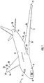
- FIG. 1 depicts a perspective view of an aircraft 2 that may incorporate embodiments of the present disclosure.
- Aircraft 2 includes a fuselage 4 extending from a nose portion 6 to a tail portion 8 through a body portion 10.
- Body portion 10 houses an aircraft cabin 14 that includes a crew compartment 15 and a passenger or cargo compartment 16.
- Body portion 10 supports a first wing 17 and a second wing 18.
- First wing 17 extends from a first root portion 20 to a first tip portion 21 through a first airfoil portion 23.
- First airfoil portion 23 includes a leading edge 25 and a trailing edge 26.
- Second wing 18 extends from a second root portion (not shown) to a second tip portion 31 through a second airfoil portion 33.
- Second airfoil portion 33 includes a leading edge 35 and a trailing edge 36.
- Tail portion 8 includes a stabilizer 38.
- Aircraft 2 includes an engine 54 configured to provide propulsion to the aircraft 2.
- the aircraft 2 also includes one or more angle
- angle of attack (AoA) sensors are utilized to indicate the angle between the chord line of an aircraft wing and a relative motion vector between the aircraft and the airflow. This measurement will provide the amount of lift generated by the aircraft wing.
- FIG. 2a depicts a side view of an angle of attack sensor according to one or more embodiments.
- the AoA sensor 200a includes a rotatable vane 202 and a stationary faceplate 204.
- FIG. 2b depicts a side view of an AoA sensor 200b depicting the rotational mechanism for the AoA vane 202 according to one or more embodiments.
- Critical areas include, but are not limited to, the stationary faceplate 204 exterior and the interior cavity regions 212 (shown as a dotted line) of the AoA sensor 200b.
- Typical heating elements include positive temperature coefficient (PTC) properties which self-regulates the heater power at higher temperatures and prevents overheating.
- PTC positive temperature coefficient
- AoA sensors require the cavities to be at a minimum of 15 degrees Celsius under dry air conditions. In the current configuration, it is a challenge to adhere to the 15 degree Celsius requirement at extremely low ambient temperatures (e.g., -44 degrees Celsius). This is due to the heater elements not being placed near the critical areas 212 to be heated (i.e., longer heat flow paths) and there is potential for heat loss paths.
- Thin film heaters can be effected for electro-thermal wing ice protection since they provide benefits of quick, uniform, and reliable heating.
- the thin film heaters are made up of nano-composites of carbon allotropes in a polymer/silicon matrix.
- a few examples of thin film heaters include positive temperature coefficient (PTC) heaters based on carbon black/polymer composite and carbon nanotube (CNT)/silicone nano composite (CNT heater).
- PTC heaters are self-regulating heaters in which the heater surfaces are heated to a pre-defined set temperature, beyond which the electric resistance drastically increases reducing the circuit current.
- CNT heaters are not self-regulating by default but could be made self-regulating by providing temperature feedback control.
- aspects of the present disclosure provide for use of thin film heaters that are placed conformally to the critical areas 212 in an angle of attack faceplate 204 for efficient heating.
- Current AoA faceplate design can be modified to enable creation of a thin film heater assembly (shown in FIG. 4 ) within an annular region or cavity (depicted in FIGs. 3a and 3b ) below the surface of the AoA faceplate 204 thus providing the heater surfaces closer to the icing critical areas (212 from FIG. 2b ).
- the faceplate can be provided with enough material thickness to maintain the structural integrity of the faceplate to withstand external loads such as vibrational as well as hail strike impact loads.
- FIG. 3a depicts a bottom view of an angle of attack sensor faceplate 301a according to one or more embodiments.
- the AoA sensor 300a includes a vane 302 and a face plate 304.
- the bottom view of the faceplate 304? depicts an annular region 308 beneath the surface of the faceplate 304.
- a thin film heating assembly (shown in FIG. 4 ) can be conformally applied to the top surface 310 of this annular region 308.
- FIG. 3b depicts a cutaway view of the angle of attack sensor faceplate 300b According to one or more embodiments. The cutaway view highlights the areas 324 than can be heated when a thin film heating assembly(shown in FIG.
- the heat transfer areas 324 inside the faceplate can be thermally insulated and protected from corrosive agents or sediments.
- An inner protective and thermally insulating cover 322 (protective cover) can be utilized and bonded to the thin film heater assembly (shown in FIG. 4 ).
- the protective cover 322 can be a thermal barrier coated metallic cover.
- FIG. 4 depicts the layers of the thin film heater apparatus according to one or more embodiments.
- the thin film heater assembly 400 includes a number of layers as shown in FIG. 4 .
- the assembly 400 can be attached to the surface 310 in the annular region 308 of the faceplate 202. depicted in FIGs. 3a and 3b .
- the assembly 400 also includes an electric insulation and adhesive layer 404 that allows for insulation and adhesion of the subsequent layers to the surface 310 of the faceplate 202.
- the next layer is the thin film heater layer 406 which can include PTC heaters or CNT heaters.
- the next layer is a second electric insulation and adhesive layer 408.
- the last layer is a protective cover and thermal insulation layer 410.
- the electric insulation and adhesive layers 404, 408 prevent current leakage to prevent short circuits.
- the adhesive ensures enhanced contact between the thin film heater layer 406 and the surface 310 of the faceplate 202 (from FIG. 2 , 3a, and 3b ) and the protective cover layer 410.
- the combined thickness of the heater layer 406, insulation layers and adhesives 404, 408 are on the order of 0.03 inches.
- the radius of curvature can be as low as 0.02 inches.
- the thin film heater assembly 400 can be created by laying out the thin film heater layer 406 with the adhesives and electrical insulation 404, 408 on the face plate surface 402 (within the annular region under the face plate) with the adhesive bonding all the layers to each other and to the faceplate surface 402.
- the separate protective 410 cover can be fastened or bonded to the thin film heater assembly by curing.
- the thin film heater assembly 400 can be bonded and cured to the protective cover 410 and then fastened to the face plate 402 for structural integrity and good contact with the surface of the face plate 402.
- the thin film heater assembly 400 can be attached to the face plate surface 402 by a fastener.
- the power densities required for an AoA heating application are of the order of 60-300 kW/m 2 for quicker heating.
- the thin film heaters are capable for customized rapid and uniform heating with the required power density (max. ⁇ 500 kW/m 2 ).
- Thin film heaters such as the CNT and PTC heaters are suited for quicker heating (e.g., in ground operations, reaching minimum 15 degrees Celsius in 3 minutes when heater is powered on). Both CNT and PTC heaters generate the required power density based on the electrical resistivity temperature characteristics.
- the AoA face plate critical surfaces are to be heated above freezing temperatures.
- Thin film heaters are made to heat surfaces to approximately 40 degrees Celsius which is more than sufficient to prevent/melt ice accumulation.
- the temperatures limit for the heater can be set at 40 degrees Celsius or below to meet the minimum temperature requirement by utilizing a standalone PTC heater or CNT heater with a temperature feedback sensor.
- the PTC heaters are capable to provide variable heat densities to areas where more heating is required. For example, in an AoA under flight conditions, due to the increase airflow over the face plate surface in the upstream, there can be a higher heat transfer coefficients. That is to say, more power density has to be placed near the upstream region. In such cases, more localized power-density could be provided near the upstream and save power by reducing power density in other areas. Power densities depend on the concentration of carbon in the matrix.
- FIG. 5 depicts a system for preventing ice accumulation in an angle of attack sensor according to one or more embodiments.
- the system 500 includes a controller 502 that is electrically and communicatively coupled to a thin film heater assembly 504.
- the thin film heaters assembly 504 can be any type of configuration including the configuration described in FIG. 4 or a CNT and PTC heater in other configurations.
- the thin film heater assembly 504 can be conformally applied to the bottom surface of an angle of attack faceplate 520 to provide heat to critical areas under the face plate 520.
- the controller 502 is configured to provide power to operate the thin film heater assembly 504.
- the controller 502 can be communicatively coupled to one or more external sensors 506 and/or the controller 502 can be communicatively coupled to one or more internal sensors within the thin film heater assembly 504.
- the internal sensors or external sensors 506 can collect temperature data associated with the AoA sensor environment to allow the controller 502 to determine that a minimum temperature is maintained in the AoA sensor.
- the internal sensors or external sensors 506 can be temperature feedback sensors to determine the temperature of the thin film heater assembly 504.
- the feedback sensors can provide temperature data for the controller 502 to utilize to operate the thin film heater assembly 504. For example, a maximum temperature can be determined to allow for sufficient heat to curb ice accumulation and also to allow for normal operation of the AoA sensor.
- the controller 502 can utilize the feedback data to control the heater assembly 504 to not go above the determined maximum temperature by either reducing the power supplied to the assembly 504 or turning the assembly off for a period of time.
- the feedback controller 502 is utilized for CNT heater assemblies.
- exemplary is used herein to mean “serving as an example, instance or illustration.” Any embodiment or design described herein as “exemplary” is not necessarily to be construed as preferred or advantageous over other embodiments or designs.
- the terms “at least one” and “one or more” may be understood to include any integer number greater than or equal to one, i.e. one, two, three, four, etc.
- the terms “a plurality” may be understood to include any integer number greater than or equal to two, i.e. two, three, four, five, etc.
- connection may include both an indirect “connection” and a direct “connection.”
Landscapes
- Engineering & Computer Science (AREA)
- Aviation & Aerospace Engineering (AREA)
- Physics & Mathematics (AREA)
- General Physics & Mathematics (AREA)
- Surface Heating Bodies (AREA)
Abstract
Description
- This application claims the benefit of Indian Patent Application number
201911051312 filed December 11, 2019 - The present invention generally relates to angle of attack sensors, and more specifically, to conformal thin film heaters for angle of attack sensors.
- For aircraft technology, angle of attack specifies the angle between the chord line of the wing of a fixed-wing aircraft and the vector representing the relative motion between the aircraft and the atmosphere. Since a wing can have twist, a chord line of the whole wing may not be definable, so an alternate reference line is simply defined. Often, the chord line of the root of the wing is chosen as the reference line. Another choice is to use a horizontal line on the fuselage as the reference line (and also as the longitudinal axis).
- Embodiments of the present invention are directed to an angle of attack sensor. A non-limiting example of the sensor includes a vane, a faceplate, an annular region under the surface of the faceplate, and a thin film heater assembly attached to a top most surface of the annual region.
- Embodiments of the present invention are directed to a system. A non-limiting example of the system includes an angle of attack sensor including a vane, a faceplate, an annular region under the surface of the faceplate, a thin film heater assembly attached to a top most surface of the annular region, a temperature feedback sensor, and a controller communicatively coupled to the thin film heater assembly, wherein the controller is configured to receive temperature data from the temperature feedback sensor, and operate the thin film heater assembly based at least in part on the temperature data.
- Additional technical features and benefits are realized through the techniques of the present invention. Embodiments and aspects of the invention are described in detail herein and are considered a part of the claimed subject matter. For a better understanding, refer to the detailed description and to the drawings.
- The specifics of the exclusive rights described herein are particularly pointed out and distinctly claimed in the claims at the conclusion of the specification. The foregoing and other features and advantages of the embodiments of the invention are apparent from the following detailed description taken in conjunction with the accompanying drawings in which:
-
FIG. 1 is a perspective view of an aircraft that may incorporate embodiments of the present disclosure; -
FIG. 2a depicts a side view of an angle of attack sensor according to one or more embodiments; -
FIG. 2b depicts a side view of an AoA sensor depicting the rotational mechanism for the AoA vane according to one or more embodiments; -
FIG. 3a depicts a bottom view of an angle of attack sensor faceplate according to one or more embodiments; -
FIG. 3b depicts a cutaway view of the angle of attack sensor faceplate according to one or more embodiments -
FIG. 4 depicts the layers of the thin film heater apparatus according to one or more embodiments; and -
FIG. 5 depicts a system for preventing ice accumulation in an angle of attack sensor according to one or more embodiments. - The diagrams depicted herein are illustrative. There can be many variations to the diagram or the operations described therein without departing from the spirit of the invention. For instance, the actions can be performed in a differing order or actions can be added, deleted or modified. Also, the term "coupled" and variations thereof describes having a communications path between two elements and does not imply a direct connection between the elements with no intervening elements/connections between them. All of these variations are considered a part of the specification.
- For the sake of brevity, conventional techniques related to making and using aspects of the invention may or may not be described in detail herein. In particular, various aspects of computing systems and specific computer programs to implement the various technical features described herein are well known. Accordingly, in the interest of brevity, many conventional implementation details are only mentioned briefly herein or are omitted entirely without providing the well-known system and/or process details.
- Referring now to the figures,
FIG. 1 depicts a perspective view of anaircraft 2 that may incorporate embodiments of the present disclosure.Aircraft 2 includes a fuselage 4 extending from a nose portion 6 to atail portion 8 through abody portion 10.Body portion 10 houses anaircraft cabin 14 that includes acrew compartment 15 and a passenger orcargo compartment 16.Body portion 10 supports afirst wing 17 and asecond wing 18.First wing 17 extends from afirst root portion 20 to afirst tip portion 21 through afirst airfoil portion 23.First airfoil portion 23 includes aleading edge 25 and a trailingedge 26.Second wing 18 extends from a second root portion (not shown) to asecond tip portion 31 through asecond airfoil portion 33.Second airfoil portion 33 includes aleading edge 35 and a trailingedge 36.Tail portion 8 includes astabilizer 38.Aircraft 2 includes an engine 54 configured to provide propulsion to theaircraft 2. Theaircraft 2 also includes one or more angle ofattack sensors 100. - Turning now to an overview of technologies that are more specifically relevant to aspects of the disclosure, angle of attack (AoA) sensors are utilized to indicate the angle between the chord line of an aircraft wing and a relative motion vector between the aircraft and the airflow. This measurement will provide the amount of lift generated by the aircraft wing.
FIG. 2a depicts a side view of an angle of attack sensor according to one or more embodiments. The AoA sensor 200a includes arotatable vane 202 and astationary faceplate 204. - The rotation of the
AoA vane 202 included in the sensor is required for the angle of attack measurement of the AoA sensor 200a. However, in icy conditions, the formation of ice in a cavity between therotational surface 204 of thevane 202 and the stationary surface of afaceplate 204 can hinder the free rotation of thevane 202. AoA sensors are, typically, mounted external to an aircraft and are equipped with appropriate heating mechanisms for ice prevention under extreme icing conditions.FIG. 2b depicts a side view of anAoA sensor 200b depicting the rotational mechanism for theAoA vane 202 according to one or more embodiments. Critical areas include, but are not limited to, thestationary faceplate 204 exterior and the interior cavity regions 212 (shown as a dotted line) of theAoA sensor 200b. Typical heating elements include positive temperature coefficient (PTC) properties which self-regulates the heater power at higher temperatures and prevents overheating. AoA sensors require the cavities to be at a minimum of 15 degrees Celsius under dry air conditions. In the current configuration, it is a challenge to adhere to the 15 degree Celsius requirement at extremely low ambient temperatures (e.g., -44 degrees Celsius). This is due to the heater elements not being placed near thecritical areas 212 to be heated (i.e., longer heat flow paths) and there is potential for heat loss paths. - Aspects of the present disclosure address the shortcomings described above by providing systems for heating portions of the angle of attack sensors and portions of an aircraft surface using thin film heaters. Thin film heaters can be effected for electro-thermal wing ice protection since they provide benefits of quick, uniform, and reliable heating. The thin film heaters are made up of nano-composites of carbon allotropes in a polymer/silicon matrix. A few examples of thin film heaters include positive temperature coefficient (PTC) heaters based on carbon black/polymer composite and carbon nanotube (CNT)/silicone nano composite (CNT heater). The thin film heaters generate surface heating when electrically energized depending on the electric resistivity-temperature characteristics of the thin film heater composite material. PTC heaters are self-regulating heaters in which the heater surfaces are heated to a pre-defined set temperature, beyond which the electric resistance drastically increases reducing the circuit current. CNT heaters are not self-regulating by default but could be made self-regulating by providing temperature feedback control.
- In one or more embodiments, aspects of the present disclosure provide for use of thin film heaters that are placed conformally to the
critical areas 212 in an angle ofattack faceplate 204 for efficient heating. Current AoA faceplate design can be modified to enable creation of a thin film heater assembly (shown inFIG. 4 ) within an annular region or cavity (depicted inFIGs. 3a and 3b ) below the surface of theAoA faceplate 204 thus providing the heater surfaces closer to the icing critical areas (212 fromFIG. 2b ). Also, the faceplate can be provided with enough material thickness to maintain the structural integrity of the faceplate to withstand external loads such as vibrational as well as hail strike impact loads. -
FIG. 3a depicts a bottom view of an angle ofattack sensor faceplate 301a according to one or more embodiments. TheAoA sensor 300a includes a vane 302 and a face plate 304. The bottom view of the faceplate 304? depicts anannular region 308 beneath the surface of the faceplate 304. In one or more embodiments, a thin film heating assembly (shown inFIG. 4 ) can be conformally applied to thetop surface 310 of thisannular region 308.FIG. 3b depicts a cutaway view of the angle ofattack sensor faceplate 300b According to one or more embodiments. The cutaway view highlights theareas 324 than can be heated when a thin film heating assembly(shown inFIG. 4 ) is conformally applied to theannular region 308 underneath the face plate 304. Theheat transfer areas 324 inside the faceplate can be thermally insulated and protected from corrosive agents or sediments. An inner protective and thermally insulating cover 322 (protective cover) can be utilized and bonded to the thin film heater assembly (shown inFIG. 4 ). Theprotective cover 322 can be a thermal barrier coated metallic cover. -
FIG. 4 depicts the layers of the thin film heater apparatus according to one or more embodiments. The thinfilm heater assembly 400 includes a number of layers as shown inFIG. 4 . Theassembly 400 can be attached to thesurface 310 in theannular region 308 of thefaceplate 202. depicted inFIGs. 3a and 3b . Theassembly 400 also includes an electric insulation andadhesive layer 404 that allows for insulation and adhesion of the subsequent layers to thesurface 310 of thefaceplate 202. The next layer is the thinfilm heater layer 406 which can include PTC heaters or CNT heaters. The next layer is a second electric insulation andadhesive layer 408. And the last layer is a protective cover andthermal insulation layer 410. The electric insulation andadhesive layers film heater layer 406 and thesurface 310 of the faceplate 202 (fromFIG. 2 ,3a, and 3b ) and theprotective cover layer 410. The combined thickness of theheater layer 406, insulation layers andadhesives - In one or more embodiments, the thin
film heater assembly 400 can be created by laying out the thinfilm heater layer 406 with the adhesives andelectrical insulation film heater assembly 400 can be bonded and cured to theprotective cover 410 and then fastened to the face plate 402 for structural integrity and good contact with the surface of the face plate 402. In one or more embodiments, the thinfilm heater assembly 400 can be attached to the face plate surface 402 by a fastener. - The power densities required for an AoA heating application are of the order of 60-300 kW/m2 for quicker heating. The thin film heaters are capable for customized rapid and uniform heating with the required power density (max. ∼ 500 kW/m2). Thin film heaters such as the CNT and PTC heaters are suited for quicker heating (e.g., in ground operations, reaching minimum 15 degrees Celsius in 3 minutes when heater is powered on). Both CNT and PTC heaters generate the required power density based on the electrical resistivity temperature characteristics.
- In one or more embodiments, the AoA face plate critical surfaces are to be heated above freezing temperatures. Thin film heaters are made to heat surfaces to approximately 40 degrees Celsius which is more than sufficient to prevent/melt ice accumulation. The temperatures limit for the heater can be set at 40 degrees Celsius or below to meet the minimum temperature requirement by utilizing a standalone PTC heater or CNT heater with a temperature feedback sensor. During the ground operation, power consumption can be made minimal with thin film heaters operating above the minimum required temperature. In one or more embodiments, the PTC heaters are capable to provide variable heat densities to areas where more heating is required. For example, in an AoA under flight conditions, due to the increase airflow over the face plate surface in the upstream, there can be a higher heat transfer coefficients. That is to say, more power density has to be placed near the upstream region. In such cases, more localized power-density could be provided near the upstream and save power by reducing power density in other areas. Power densities depend on the concentration of carbon in the matrix.
-
FIG. 5 depicts a system for preventing ice accumulation in an angle of attack sensor according to one or more embodiments. Thesystem 500 includes acontroller 502 that is electrically and communicatively coupled to a thinfilm heater assembly 504. The thinfilm heaters assembly 504 can be any type of configuration including the configuration described inFIG. 4 or a CNT and PTC heater in other configurations. The thinfilm heater assembly 504 can be conformally applied to the bottom surface of an angle ofattack faceplate 520 to provide heat to critical areas under theface plate 520. Thecontroller 502 is configured to provide power to operate the thinfilm heater assembly 504. In addition, thecontroller 502 can be communicatively coupled to one or moreexternal sensors 506 and/or thecontroller 502 can be communicatively coupled to one or more internal sensors within the thinfilm heater assembly 504. As mentioned above, the internal sensors orexternal sensors 506 can collect temperature data associated with the AoA sensor environment to allow thecontroller 502 to determine that a minimum temperature is maintained in the AoA sensor. In addition, the internal sensors orexternal sensors 506 can be temperature feedback sensors to determine the temperature of the thinfilm heater assembly 504. The feedback sensors can provide temperature data for thecontroller 502 to utilize to operate the thinfilm heater assembly 504. For example, a maximum temperature can be determined to allow for sufficient heat to curb ice accumulation and also to allow for normal operation of the AoA sensor. Thecontroller 502 can utilize the feedback data to control theheater assembly 504 to not go above the determined maximum temperature by either reducing the power supplied to theassembly 504 or turning the assembly off for a period of time. Thefeedback controller 502 is utilized for CNT heater assemblies. - The term "about" is intended to include the degree of error associated with measurement of the particular quantity based upon the equipment available at the time of filing the application. For example, "about" can include a range of ± 8% or 5%, or 2% of a given value.
- The terminology used herein is for the purpose of describing particular embodiments only and is not intended to be limiting of the present disclosure. As used herein, the singular forms "a", "an" and "the" are intended to include the plural forms as well, unless the context clearly indicates otherwise. It will be further understood that the terms "comprises" and/or "comprising," when used in this specification, specify the presence of stated features, integers, steps, operations, elements, and/or components, but do not preclude the presence or addition of one or more other features, integers, steps, operations, element components, and/or groups thereof.
- Various embodiments of the invention are described herein with reference to the related drawings. Alternative embodiments of the invention can be devised without departing from the scope of this invention. Various connections and positional relationships (e.g., over, below, adjacent, etc.) are set forth between elements in the following description and in the drawings. These connections and/or positional relationships, unless specified otherwise, can be direct or indirect, and the present invention is not intended to be limiting in this respect. Accordingly, a coupling of entities can refer to either a direct or an indirect coupling, and a positional relationship between entities can be a direct or indirect positional relationship. Moreover, the various tasks and process steps described herein can be incorporated into a more comprehensive procedure or process having additional steps or functionality not described in detail herein.
- The following definitions and abbreviations are to be used for the interpretation of the claims and the specification. As used herein, the terms "comprises," "comprising," "includes," "including," "has," "having," "contains" or "containing," or any other variation thereof, are intended to cover a non-exclusive inclusion. For example, a composition, a mixture, process, method, article, or apparatus that comprises a list of elements is not necessarily limited to only those elements but can include other elements not expressly listed or inherent to such composition, mixture, process, method, article, or apparatus.
- Additionally, the term "exemplary" is used herein to mean "serving as an example, instance or illustration." Any embodiment or design described herein as "exemplary" is not necessarily to be construed as preferred or advantageous over other embodiments or designs. The terms "at least one" and "one or more" may be understood to include any integer number greater than or equal to one, i.e. one, two, three, four, etc. The terms "a plurality" may be understood to include any integer number greater than or equal to two, i.e. two, three, four, five, etc. The term "connection" may include both an indirect "connection" and a direct "connection."
- While the present disclosure has been described with reference to an exemplary embodiment or embodiments, it will be understood by those skilled in the art that various changes may be made and equivalents may be substituted for elements thereof without departing from the scope of the present disclosure. In addition, many modifications may be made to adapt a particular situation or material to the teachings of the present disclosure without departing from the essential scope thereof. Therefore, it is intended that the present disclosure not be limited to the particular embodiment disclosed as the best mode contemplated for carrying out this present disclosure, but that the present disclosure will include all embodiments falling within the scope of the claims.
Claims (11)
- An angle of attack sensor comprising:a vane (202);a faceplate (204);an annular region (308) defined in the faceplate; anda thin film heater assembly (400) attached to a surface of the annual region defined in the faceplate.
- The angle of attack sensor of Claim 1, wherein the thin film heater assembly is attached to the surface of the annual region by an adhesive.
- The angle of attack sensor of Claim 1, wherein the thin film heater assembly is attached to the surface of the annual region by a curing process.
- The angle of attack sensor of any preceding Claim, wherein the thin film heater assembly comprises:a first film adhesive layer;a first electrical insulator layer;a thin film heater layer;a second film adhesive layer; anda second electrical insulator layer.
- The angle of attack sensor of Claim 4, wherein the thin film heater assembly further comprises a thermal insulator layer.
- The angle of attack sensor of Claim 4, wherein the thin film heater layer comprising positive temperature coefficient (PTC) heater.
- The angle of attack sensor of Claim 4, wherein the thin film heater layer comprising a carbon nanotube (CNT) heater.
- The angle of attack sensor of Claim 4, wherein the annular region comprises a first region and a second region;
wherein the thin film heater layer comprises a first thickness in the first region; and wherein the thin film heater layer comprises a second thickness in the second region. - The angle of attack sensor of Claim 1, wherein the thin film heater assembly is attached to the surface of the annual region by a fastener.
- The angle of attack sensor of Claim 1, wherein the thin film heater assembly is attached conformally to the surface of the annular region.
- A system comprising:the angle of attack sensor of any preceding claimfurther comprising:a temperature feedback sensor; anda controller communicatively coupled to the thin film heater assembly, wherein the controller is configured to:receive temperature data from the temperature feedback sensor; andoperate the thin film heater assembly based at least in part on the temperature data.
Applications Claiming Priority (1)
| Application Number | Priority Date | Filing Date | Title |
|---|---|---|---|
| IN201911051312 | 2019-12-11 |
Publications (1)
| Publication Number | Publication Date |
|---|---|
| EP3836747A1 true EP3836747A1 (en) | 2021-06-16 |
Family
ID=73793125
Family Applications (1)
| Application Number | Title | Priority Date | Filing Date |
|---|---|---|---|
| EP20213179.3A Pending EP3836747A1 (en) | 2019-12-11 | 2020-12-10 | Conformal thin film heaters for angle of attack sensors |
Country Status (2)
| Country | Link |
|---|---|
| US (1) | US11814181B2 (en) |
| EP (1) | EP3836747A1 (en) |
Cited By (1)
| Publication number | Priority date | Publication date | Assignee | Title |
|---|---|---|---|---|
| EP4111213A4 (en) * | 2020-02-25 | 2024-02-21 | Rosemount Aerospace Inc. | INCLINED FACEPLATE ATTACK ANGLE SENSOR |
Families Citing this family (2)
| Publication number | Priority date | Publication date | Assignee | Title |
|---|---|---|---|---|
| CN112572808B (en) * | 2020-12-31 | 2023-02-10 | 南京航空航天大学 | Double-layer anti-icing and electric heating structure and wing adopting same |
| FR3165241A1 (en) * | 2024-08-02 | 2026-02-06 | Thales | Aerodynamic measuring device |
Citations (5)
| Publication number | Priority date | Publication date | Assignee | Title |
|---|---|---|---|---|
| US2918817A (en) * | 1955-10-03 | 1959-12-29 | G M Giannini & Co Inc | Fluid stream direction indicator with mechanical filter |
| EP2950106A1 (en) * | 2014-05-28 | 2015-12-02 | The Boeing Company | External case heater for an angle of attack sensor |
| EP3297395A2 (en) * | 2016-09-20 | 2018-03-21 | Goodrich Corporation | Thermally conductive, electrically insulating protection layer for de-icing heaters |
| EP3321692A1 (en) * | 2016-11-09 | 2018-05-16 | Honeywell International Inc. | Air data probe with thin film heating system and method of manufacturing the air data probe |
| EP3478025A1 (en) * | 2017-09-29 | 2019-05-01 | Rosemount Aerospace Inc. | Self-regulating heater compensation |
Family Cites Families (13)
| Publication number | Priority date | Publication date | Assignee | Title |
|---|---|---|---|---|
| US4121088A (en) * | 1976-10-18 | 1978-10-17 | Rosemount Inc. | Electrically heated air data sensing device |
| US6076963A (en) * | 1998-10-20 | 2000-06-20 | Avionics Specialties, Inc. | Aircraft probe with integral air temperature sensor |
| US6941805B2 (en) | 2003-06-26 | 2005-09-13 | Rosemount Aerospace Inc. | Multi-function air data sensing probe having an angle of attack vane |
| FR2924498B1 (en) | 2007-11-30 | 2009-12-11 | Thales Sa | WIND ORIENTATION MEASURING WINDOW WITH INTEGRATED HEATER |
| US9097734B2 (en) | 2012-01-04 | 2015-08-04 | Amphenol Thermometrics, Inc. | Ceramic heating device |
| US11542018B2 (en) * | 2015-01-06 | 2023-01-03 | Battelle Memorial Institute | Uniform heat distribution in resistive heaters for anti-icing and de-icing |
| CA2919341C (en) | 2015-04-02 | 2022-11-15 | Rosemount Aerospace, Inc. | Corrosion-resistant heated air data probe |
| US10179654B2 (en) | 2015-10-20 | 2019-01-15 | Honeywell International Inc. | Architecture for air data probe power supply control |
| US10464680B2 (en) * | 2016-08-30 | 2019-11-05 | The Boeing Company | Electrically conductive materials for heating and deicing airfoils |
| CN206908878U (en) * | 2017-03-16 | 2018-01-19 | 苏州汉纳材料科技有限公司 | Ultra-thin carbon nanotube heating element heater and ultra-thin carbon nanotube skirting heater |
| US10393766B2 (en) | 2017-08-17 | 2019-08-27 | Rosemount Aerospace Inc. | Water management system for angle of attack sensors |
| US11105691B2 (en) | 2018-03-30 | 2021-08-31 | Honeywell International Inc. | Self-regulating heating system for a total air temperature probe |
| US10877062B2 (en) * | 2018-05-09 | 2020-12-29 | Rosemount Aerospace Inc. | Aft-located heated ramp for ice and water management of angle of attack sensors |
-
2020
- 2020-02-05 US US16/782,131 patent/US11814181B2/en active Active
- 2020-12-10 EP EP20213179.3A patent/EP3836747A1/en active Pending
Patent Citations (5)
| Publication number | Priority date | Publication date | Assignee | Title |
|---|---|---|---|---|
| US2918817A (en) * | 1955-10-03 | 1959-12-29 | G M Giannini & Co Inc | Fluid stream direction indicator with mechanical filter |
| EP2950106A1 (en) * | 2014-05-28 | 2015-12-02 | The Boeing Company | External case heater for an angle of attack sensor |
| EP3297395A2 (en) * | 2016-09-20 | 2018-03-21 | Goodrich Corporation | Thermally conductive, electrically insulating protection layer for de-icing heaters |
| EP3321692A1 (en) * | 2016-11-09 | 2018-05-16 | Honeywell International Inc. | Air data probe with thin film heating system and method of manufacturing the air data probe |
| EP3478025A1 (en) * | 2017-09-29 | 2019-05-01 | Rosemount Aerospace Inc. | Self-regulating heater compensation |
Cited By (4)
| Publication number | Priority date | Publication date | Assignee | Title |
|---|---|---|---|---|
| EP4111213A4 (en) * | 2020-02-25 | 2024-02-21 | Rosemount Aerospace Inc. | INCLINED FACEPLATE ATTACK ANGLE SENSOR |
| US12339294B2 (en) | 2020-02-25 | 2025-06-24 | Rosemount Aerospace Inc. | Angle of attack sensor vane geometry |
| US12345731B2 (en) | 2020-02-25 | 2025-07-01 | Rosemount Aerospace Inc. | Angle of attack sensor with integral bearing support cage |
| US12360134B2 (en) | 2020-02-25 | 2025-07-15 | Rosemount Aerospace Inc. | Angle of attack sensor with sloped faceplate |
Also Published As
| Publication number | Publication date |
|---|---|
| US11814181B2 (en) | 2023-11-14 |
| US20210179278A1 (en) | 2021-06-17 |
Similar Documents
| Publication | Publication Date | Title |
|---|---|---|
| US11814181B2 (en) | Conformal thin film heaters for angle of attack sensors | |
| US8602359B2 (en) | Ice protection system | |
| EP3321692B1 (en) | Air data probe with thin film heating system and method of manufacturing the air data probe | |
| US9884685B2 (en) | External case heater for an angle of attack sensor | |
| US8397563B2 (en) | Aeronautical probe with integrated heater | |
| US9771158B2 (en) | Ice protection of aerodynamic surfaces | |
| Roy et al. | Multiphysics anti-icing simulation of a CFRP composite wing structure embedded with thin etched-foil electrothermal heating films in glaze ice conditions | |
| CA2609119C (en) | Strained capable conductive/resistive composite hybrid heater for thermal anti-ice device | |
| US10822097B2 (en) | Ice formation detection and removal system for an aerial vehicle and method | |
| EP1820943A2 (en) | Heater assembly for deicing and/or anti-icing a component | |
| EP3450320B1 (en) | Tailored rotor-blade ice-protection system | |
| US11008109B2 (en) | Aircraft ice protection systems | |
| US8714489B2 (en) | Structural bonding arrangement | |
| EP1200308A1 (en) | Zoned aircraft de-icing system and method | |
| JP2000356358A (en) | Plate structural member of floor surface plate particularly for aircraft | |
| CN106585998B (en) | Architecture for Air Data Probe Power Control | |
| CN111328159A (en) | Multilayer structure with carbon nanotube heater | |
| US20200361612A1 (en) | Resistive heated aircraft component and method for manufacturing said aircraft component | |
| CN110615107A (en) | Heatable leading edge device, leading edge heating system and aircraft with same | |
| WO2019116671A1 (en) | Fan blade, engine, and anti-icing/de-icing function-equipped structure | |
| US11591959B2 (en) | Generator air gap heater | |
| CA2375544C (en) | Aircraft de-icing system | |
| CN114007288A (en) | PTC flexible heating film and heating assembly for helicopter tail blade anti-icing | |
| EP3639622B1 (en) | Flexible resistor | |
| US20190309960A1 (en) | Heatable floor panel and floor heating system for an aircraft |
Legal Events
| Date | Code | Title | Description |
|---|---|---|---|
| PUAI | Public reference made under article 153(3) epc to a published international application that has entered the european phase |
Free format text: ORIGINAL CODE: 0009012 |
|
| STAA | Information on the status of an ep patent application or granted ep patent |
Free format text: STATUS: THE APPLICATION HAS BEEN PUBLISHED |
|
| AK | Designated contracting states |
Kind code of ref document: A1 Designated state(s): AL AT BE BG CH CY CZ DE DK EE ES FI FR GB GR HR HU IE IS IT LI LT LU LV MC MK MT NL NO PL PT RO RS SE SI SK SM TR |
|
| STAA | Information on the status of an ep patent application or granted ep patent |
Free format text: STATUS: REQUEST FOR EXAMINATION WAS MADE |
|
| 17P | Request for examination filed |
Effective date: 20211214 |
|
| RBV | Designated contracting states (corrected) |
Designated state(s): AL AT BE BG CH CY CZ DE DK EE ES FI FR GB GR HR HU IE IS IT LI LT LU LV MC MK MT NL NO PL PT RO RS SE SI SK SM TR |
|
| STAA | Information on the status of an ep patent application or granted ep patent |
Free format text: STATUS: EXAMINATION IS IN PROGRESS |
|
| 17Q | First examination report despatched |
Effective date: 20221010 |