EP2950106A1 - External case heater for an angle of attack sensor - Google Patents
External case heater for an angle of attack sensor Download PDFInfo
- Publication number
- EP2950106A1 EP2950106A1 EP15165557.8A EP15165557A EP2950106A1 EP 2950106 A1 EP2950106 A1 EP 2950106A1 EP 15165557 A EP15165557 A EP 15165557A EP 2950106 A1 EP2950106 A1 EP 2950106A1
- Authority
- EP
- European Patent Office
- Prior art keywords
- heating apparatus
- aoa sensor
- temperature
- support element
- heating
- Prior art date
- Legal status (The legal status is an assumption and is not a legal conclusion. Google has not performed a legal analysis and makes no representation as to the accuracy of the status listed.)
- Granted
Links
Images


Classifications
-
- B—PERFORMING OPERATIONS; TRANSPORTING
- B64—AIRCRAFT; AVIATION; COSMONAUTICS
- B64D—EQUIPMENT FOR FITTING IN OR TO AIRCRAFT; FLIGHT SUITS; PARACHUTES; ARRANGEMENTS OR MOUNTING OF POWER PLANTS OR PROPULSION TRANSMISSIONS IN AIRCRAFT
- B64D15/00—De-icing or preventing icing on exterior surfaces of aircraft
- B64D15/12—De-icing or preventing icing on exterior surfaces of aircraft by electric heating
- B64D15/14—De-icing or preventing icing on exterior surfaces of aircraft by electric heating controlled cyclically along length of surface
-
- G—PHYSICS
- G01—MEASURING; TESTING
- G01P—MEASURING LINEAR OR ANGULAR SPEED, ACCELERATION, DECELERATION, OR SHOCK; INDICATING PRESENCE, ABSENCE, OR DIRECTION, OF MOVEMENT
- G01P13/00—Indicating or recording presence, absence, or direction, of movement
- G01P13/02—Indicating direction only, e.g. by weather vane
- G01P13/025—Indicating direction only, e.g. by weather vane indicating air data, i.e. flight variables of an aircraft, e.g. angle of attack, side slip, shear, yaw
Definitions
- An aircraft may use one or more sensors to determine the aircraft's angle of attack (AoA).
- AoA angle of attack
- an aircraft may have a sensor mounted to the outside of the aircraft.
- the sensor may be used to measure localized airstream angle with respect to a fuselage horizontal reference plane or a wing reference plane.
- Some sensors use a rotatable appendage affixed to the sensor.
- the rotatable appendage may have a profile that causes the appendage to seek a neutral or zero angle with respect to the direction of the local airstream around the appendage. As the direction of the local airstream changes, the rotatable appendage preferable rotates to maintain the zero angle with respect to the local airstream around the appendage.
- the amount of rotation of the appendage may be detected by the AoA sensor.
- the sensor or other cooperative systems, uses the rotation of the appendage to determine the direction of local airflow around the appendage.
- the angular difference between the direction of local airflow and the horizontal reference plane of the aircraft is the AoA. Because at least a part of the AoA sensor is exposed to the environment, the sensor may experience technical issues as a result of environment effects.
- a heating apparatus for use on an AoA sensor.
- the heating apparatus includes a support element configured for releasable engagement with the AoA sensor, a heating element bonded to the support element to form a composite structure, and a control thermostat configured to receive a temperature input and allow current to flow through a resistive element at or below a first temperature and reduce current flow through the resistive element at or above a second temperature.
- an AoA sensor system for an aircraft includes an airfoil-shaped body affixed to a rotatable mount, the rotatable mount rotatably affixed to the AoA sensor, and a heating apparatus removably affixed to the AoA sensor and configured to reduce ice formation on the AoA sensor.
- the heating apparatus includes a support element configured for releasable engagement with the AoA sensor, a heating element bonded to the support element to form a composite structure, and a control thermostat configured to receive a temperature input and allow current to flow through a resistive element at or below a first temperature and reduce current flow through the resistive element at or above a second temperature.
- a method for heating an AoA sensor includes receiving an input of a temperature of a surface of the AoA sensor, in response to detecting that the temperature is at or below a first temperature set point, allowing current to flow through a heating element of a heating apparatus in thermal contact with the AoA sensor, the heating apparatus abutted to an inner surface of a faceplate of the AoA sensor, and the heating element bonded to a support element of the heating apparatus, and in response to detecting that the temperature is at or above a second temperature set point, reducing current flow through the heating element.
- the heating apparatus may be removably affixed to an outer casing of an AoA sensor to reduce the probability of ice formation in certain areas of the AoA sensor.
- the heating apparatus includes a conductive heating element bonded to at least a portion of a support element.
- the heating element can be formed from one or more layers of a polymer.
- the heating apparatus can further include an electrical system to provide power to the heating element.
- the heating apparatus may be installed at a location to reduce the probability of ice formation in an area between an airfoil-shaped body of the AoA sensor and its faceplate.
- an airfoil-shaped body may be installed on a rotatable mount (sometimes referred to as a slinger).
- a rotatable mount sometimes referred to as a slinger
- water may be present in the interface between the rotatable mount/airfoil-shaped body and other components of the AoA sensor, including the faceplate to which the rotatable mount and airfoil-shaped body are in close proximity to. Under certain weather conditions, the water present in the interface may freeze, preventing the free rotation of the rotatable mount. Because of the location of ice formation, a case heater and an airfoil heater may be ineffective in increasing the temperature of components proximate to the interface.
- the presently disclosed heating apparatus may be installed in a location suitable to increase the temperature.
- FIG. 1 is a side view of an aircraft 100 in which an AoA sensor 104 has been affixed according to at least one embodiment disclosed herein.
- the AoA sensor 104 includes an airfoil-shaped body 106 that is rotatable.
- the airfoil-shaped body 106 is configured to rotate in response to the effects of air moving across the surface of the airfoil-shaped body 106.
- the airfoil-shaped body 106 maintains a zero degree angle in relation to the direction of airflow.
- a zero degree angle means that the airfoil-shaped body 106 is parallel, or nearly parallel, to the direction of airflow moving across the airfoil-shaped body 106.
- the airfoil-shaped body 106 will rotate to maintain or achieve a zero degree angle in relation to the direction of the airflow.
- the angle of rotation of the airfoil-shaped body 106 is measured and used to determine the angle of attack for the aircraft 100.
- Portions of the AoA sensor 104 may be exposed to the environment. In some instances, water may seep into various portions of the AoA sensor 104. If water is able to seep into certain areas in the AoA sensor 104, the ability of the airfoil-shaped body 106 to rotate may be impeded if the water freezes. If ice forms in certain locations, in response to a change in the direction of airflow across its surface, the airfoil-shaped body 106 may rotate at a slower speed, and may not rotate at all. Thus, the AoA sensor 104 may output an incorrect angle of attack. To reduce the probability of ice formation, a heating apparatus may be used.
- FIG. 2 is a cross-sectional view of the AoA sensor 104 using a heating apparatus 208 to maintain the temperature of a portion of the AoA sensor 104 according to at least one embodiment disclosed herein.
- the AoA sensor 104 includes outer casing 210.
- the outer casing 210 is configured to enclose an inner volume 212 of the AoA sensor 104.
- the inner volume 212 is defined by the inner surface of the outer casing 210.
- the inner volume 212 is used to enclose and protect various electrical and mechanical componentry of the AoA sensor 104 from the environment. But, some portions of the AoA sensor 104 are exposed to the environment.
- the airfoil-shaped body 106 is exposed to the outside airflow.
- the airfoil-shaped body 106 is affixed to a rotatable mount 214.
- the rotatable mount 214 does not sit flush, or abut, the AoA sensor 104, leaving a space 216 between the rotatable mount 214 and the AoA sensor 104.
- An example of the space 216 is illustrated using a cross hatch pattern. In some configurations, water can enter the space 216 and freeze, impeding the rotation of the rotatable mount 214.
- the heating apparatus 208 may be used.
- the heating apparatus 208 includes a support element 218 and a heating element 220.
- the heating element 220 may be a resistive element that, when a certain amount of current is applied, generates heat.
- the heating apparatus 208 surrounds at least a portion of the outer casing 210.
- the heating apparatus 208 preferably is in direct contact with the outer casing 210. Heat generated by the heating apparatus 208 is configured to raise the temperature of the outer casing 210 and the faceplate 222.
- the heat from the outer casing 210 preferably raises the temperature of the face plate 222 of the AoA sensor 104.
- the increase in temperature of the faceplate 222 preferably reduces the probability that ice will form in the space 216 between the faceplate 222 and the rotatable mount 214.
- the reduction of the probability of the buildup of ice can increase the reliability and accuracy of the AoA sensor 104.
- increased heat transfer may be provided by abutting the heating apparatus 208 to an inner surface 223 of the faceplate 222.
- the support element 218 of the heating apparatus 208 may be used to provide structural support to the heating apparatus 208.
- the heating apparatus 208 is securely affixed to the outer casing 210.
- the heating apparatus 208 may have a level of rigidity able to withstand the forces of securement. Further, it may be necessary that the heating apparatus 208 has a level of rigidity able to withstand forces, especially vibrational forces, experienced during the operation of the aircraft 100.
- the support element 218 may be, in a configuration, a metal collar.
- the support element 218 may provide a substrate upon which the heating element 220 is affixed.
- the heating element 220 is manufactured from one or more polymeric components.
- the heating element 220 may be formed from one or more "polymer blacks," e.g. polyacetylene, polypyrrole, polyaniline, p-phenylene vinylene, and their copolymers.
- the heating element 220 is a polymeric material with a suitable amount of conductive substance, such as carbon black, added to the polymeric material to achieve a desired level of conductivity.
- the heating element 220 may be a metallic-based heating element that uses a metallic conducting element, such as copper, silver, gold, or aluminum, to act as the conductor in the heating element 220.
- the heating element 220 is affixed or bonded directly to the support element 218 using a bonding agent 224 to form a composite structure configured to act as an electrical heating element.
- the bonding agent 224 may be any suitable material for bonding the heating element 220 to the support element 218.
- the bonding agent 224 may be a polyimide adhesive.
- the bonding agent 224 may be activated and cause the heating element 220 to be bonded to the support element 218 using various processes, including the use of an autoclave.
- a polyimide adhesive may be beneficial because of the general characteristics of polyimide adhesives. Some characteristics include a relatively good thermal stability, a low dielectric constant, and a relatively high level of chemical resistivity.
- the heating apparatus 208 may also include insulation 226.
- the insulation 226 may be configured to reduce the amount of heat lost from the heating apparatus 208 into the environment, and increase the amount of heat transferred to various locations of the AoA sensor 104, such as the face plate 222.
- the insulation 226 may be formed from appropriate, thermally insulative materials.
- the insulation 226 may be formed from a heat reflective metal, ceramic, glass fiber sheet/matting, silica, mica, glass wool, asbestos, silk wool, and thermally insulative polymers.
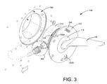
- FIG. 3 is an exploded perspective view of the AoA sensor 104 according to at least one embodiment disclosed herein.
- the AoA sensor 104 includes the airfoil-shaped body 106 affixed to the rotatable mount 214.
- the rotatable mount 214 is rotatably affixed to the faceplate 222.
- the faceplate 222 is removably cooperatively affixed to a sensor receiving area 302 of the aircraft 100.
- the faceplate 222 is sized to fit within the sensor receiving area 302 to provide a flush mount for the AoA sensor 104.
- the faceplate 222 may be affixed to the sensor receiving area 302 using screws, such as the screw 304.
- FIG. 4 is a perspective view of the heating apparatus 208 according to at least one embodiment disclosed herein.
- the heating apparatus 208 includes a support element 218 and a heating element 220.
- the heating element 220 is disposed around at least a portion of the support element 218.
- the support element 218, along with the heating element 220, may be removably installed on the AoA sensor 104.
- the heating element 220 may be a resistive, or Joule, heating element.
- a resistive heating element creates heat when current is passed through the resistive heating element.
- the resistance of the resistive heating element causes heat to be generated.
- the heating element 220 may also be constructed from materials such as nichrome, resistive wire or braid, etched foil, ceramics such as molybdenum disilicide, and composite heating elements. It should be understood, though, that other materials may be used and are considered to be within the scope of the present disclosure. Further, it should be understood that the present disclosure is not limited to resistive heating elements, as other types of heating elements may be used and are considered to be within the scope of the present disclosure.
- the heating element 220 may receive electrical power through electrical wires 400 and 402.
- the wires 400 and 402 may provide an electrical path from an electrical source to provide current to the heating element 220.
- the electrical current may be controlled in various ways to increase or decrease the temperature of the heating element 220.
- a control thermostat 404 may be used.
- the control thermostat 404 may be configured to detect the temperature of the heating element 220.
- the control thermostat 404 may close a previously open switch (not shown) internal to the control thermostat 404. Closing the switch may cause the formation of a closed loop, allowing current to flow through the wires 400 and 402.
- the control thermostat 404 opens the switch, preventing or reducing the flow of current through the wires 400 and 402.
- the temperature of the heating element 220 may be controlled by the control thermostat 404.
- the first temperature may be a temperature to reduce ice formation.
- the second temperature may be a temperature to prevent damage to the AoA sensor 104.
- control thermostat 404 may operate as a type of proportional-integral-derivative (PID) controller.
- PID controller calculates an "error" value as the difference between a measured process variable and a desired set point. The controller attempts to minimize the error in outputs by adjusting the process control inputs.
- the control thermostat 404 is a PID controller, instead of an "off or on” functionality, the control thermostat may incrementally increase or incrementally decrease the current flow to the heating element 220 to maintain a temperature.
- the control thermostat 404 may receive the temperature input from temperature detectors 408A-408N (hereinafter collectively referred to as the "temperature detectors 408").
- the temperature detectors 408 may be one or more devices that sense a temperature at a location in the AoA sensor 104 or the heating apparatus 208, or both.
- the temperature detectors 408 are further configured to provide a temperature output to the control thermostat 404.
- the control thermostat 404 is configured to receive the temperature output.
- the temperature detectors 408 may be located in various locations to provide a range of temperature inputs to the control thermostat 404.
- the control thermostat 404 may have internal temperature detectors 408. In other configurations, the temperature detectors 408 may be external to the control thermostat 404 and placed in various locations.
- the heating apparatus 208 may receive power through electrical leads 410.
- the electrical leads 410 may introduce various types of power into the heating apparatus 208.
- the heating apparatus 208 is provided power in an independent manner from the AoA sensor 104.
- the heating apparatus 208 may be part of an aircraft's Air Data Heat System.
- the Air Data Heat System may also control and power the AoA sensor 104 in an independent manner from the heating apparatus 208.
- Power may be provided to the heating apparatus 208 either manually or automatically.
- the heating apparatus 208 may be activated by the flight crew per a checklist, or automatically (independent of manual activation or deactivation) by other airplane means, such as when the flight crew activates the engine's fuel switches.
- the heating apparatus 208 may be secured around the AoA sensor 104 using a hinge 406, illustrated in further detail in FIG. 5 .
- An additional configuration of the heating apparatus 208 is shown in a cross-sectional view in FIG. 7 taken across plane T of FIG. 4 .
- FIG. 5 is a bottom view of the heating apparatus 208 in an open configuration according to at least one embodiment disclosed herein.
- the support element 218 of the heating apparatus 208 has been opened using the hinge 406.
- the hinge 406 provides a point of rotation to which a first end 502 of the support element 218 and a second end 504 of the support element.
- the space provided by the separation may be used to place the heating apparatus 208 onto the outer casing 210 of the AoA sensor 104.
- the first end 502 may be releasably affixed to the second end 504 through the use of a fastener, illustrated in further detail in FIG. 6 .
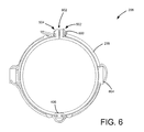
- FIG. 6 is a top view of the heating apparatus 208 in a closed configuration according to at least one embodiment disclosed herein.
- the first end 502 is releasably affixed to the second end 504 using a fastener 600.
- the fastener 600 may be constructed in any manner suitable to secure the first end 502 to the second end 504. It should be understood that other configurations of the presently disclosed subject matter may forego the use of the fastener 600.
- the hinge 406 may be a spring-loaded hinge designed to exert a closing force on the support element 218 of the heating apparatus 208.
- the heating apparatus 208 may be desirable or necessary to provide a means to indicate that the heating apparatus 208 has been secured affixed to the outer casing 210 of the AoA sensor 104.
- a technician may use the fastener 600.
- the heating apparatus 208 when installed, has void 602 defined by the area between the first end 502 and the second end 504. The void 602 may be used as an indicator that the heating apparatus 208 is fully installed on the AoA sensor 104.
- the absence of the void 602 may indicate that the inner diameter of the heating apparatus 208 is too large for the AoA sensor 104 and, thus, may extricate from the AoA sensor 104.
- the absence of the void 602 may also indicate an over-tightening of the heating apparatus 208, possibly indicating damage to the outer casing 210.
- FIG. 6 also illustrates a fuse 604.
- the fuse 604 may fault or open in various situations.
- the fuse 604 may open in an overcurrent or over-temperature condition.
- the fuse 604 may open in the event the control thermostat 404 fails closed. If the control thermostat 404 fails closed, there may be no means of heater shutoff. In this example, therefore, the fuse 604 may provide a means to prevent the over-temperature condition.
- FIG. 7 is a cross-sectional view of a portion of the heating apparatus 208 taken across the plane T illustrated in FIG. 4 according to at least one embodiment disclosed herein.
- the heating apparatus 208 includes the support element 218, the heating element 220 disposed proximate to an outer surface of the heating apparatus 208, and the insulation 226 installed around at least a portion of the heating apparatus.
- a bonding agent may be used to affix the heating element 220 to the support element 218, such as the bonding agent 224.
- At least a portion of the support element 218 abuts a portion of the outer casing 210.
- the surface of the support element 218 in contact with the outer casing may have a smooth or semi-smooth finish to provide a better heat transfer interface.
- the heat generated by the heating element 220 may be transferred to the support element 218 and may flow in two general directions: radially in the direction of X ⁇ A and laterally in the direction of X ⁇ B. If the total heat generated by the heating element 220 flows primarily in the direction X ⁇ A, the temperature of the inner volume 212 of the AoA sensor 104 may be affected, while the temperature of the space 216 (a location for possible ice formation) may be effected in an amount unsuitable to reduce the probability of ice formation. In a different manner, if the total heat generated by the heating element 220 flows primarily in the direction X ⁇ B, the temperature of the space 216 may be affected in a suitable amount, thus reducing the probability of ice formation.
- the support element 218 may include a flange 700 having a radial portion 702 and a lateral portion 704.
- the flange 700 may abut the inner surface 223 of the face plate 222, as illustrated in FIG. 2 , above.
- the lateral portion 704 in combination with the radial portion 702 of the flange 700 may present a larger heat transfer surface area for the transfer of heat to space 216 than would otherwise be present without lateral portion 704 of the flange 700.
- the larger heat transfer surface area may increase the heat flow generated by the heating element 220 in the lateral direction X ⁇ B towards the inner surface of the face plate 222.
- the increased heat flow may "focus" the heat generated by the heating element 220 towards an area of concern, such as the space 216, rather than other areas of less concern, such as the inner volume 212 of the AoA sensor 104.
- a portion of the heating element 220 may be disposed on the flange 700.
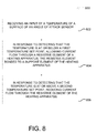
- FIG. 8 illustrates one configuration of a routine 800 for operating an AoA sensor heating apparatus according to at least one embodiment disclosed herein. Unless otherwise indicated, more or fewer operations may be performed than shown in the figures and described herein. Additionally, unless otherwise indicated, these operations may also be performed in a different order than those described herein.
- the routine 800 commences at operation 802, where an input of a temperature of a surface of an AoA sensor is received.
- the temperature may be received directly by the control thermostat 404 via direct thermal contact.
- the temperature may be received by external temperature detectors 408.
- the surface may be one of several surfaces monitored in the AoA sensor 104.
- the one or more surfaces are selected based on the probability that conditions conducive to ice formation can be detected at the one or more surfaces.
- the temperature may be a space surrounding one or more components of the AoA sensor 104.
- the temperatures may be detected using the temperature detectors 408.
- the detected temperature may be outputted to the control thermostat 404, which may receive the temperature output as an input.
- the routine 800 continues to operation 804, where in response to detecting that the temperature is at or below a first temperature set point, allowing current to flow through a resistive element of a heating apparatus, the resistive element bonded to a support element.
- the resistive element may be the heating element 220 of the AoA sensor 104.
- the support element may be the support element 218 of the AoA sensor 104.
- the first temperature may be a temperature to reduce ice formation.
- the routine 800 continues to operation 806, where in response to detecting that the temperature is at or above a second temperature set point, reducing current flow through the resistive element of the AoA sensor 104.
- the second temperature may be a temperature to prevent damage to the AoA sensor 104.
- the routine thereafter ends.
- a heating apparatus 208 for use on an AoA sensor 104 comprising:
- heating element 220 is formed of material selected from the group consisting of polyacetylene, polypyrrole, polyaniline, and p-phenylene vinylene, and copolymers of polyacetylene, polypyrrole, polyaniline, and p-phenylene vinylene.
- An AoA sensor system for an aircraft comprising: an AoA sensor 104 comprising an airfoil-shaped body 106 affixed to a rotatable mount 214; the rotatable mount 214 rotatably affixed to the AoA sensor 104; and a heating apparatus 208 removably affixed to the AoA sensor 104 and configured to reduce ice formation on the AoA sensor 104, the heating apparatus comprising a support element 218 configured for releasable engagement with the AoA sensor 104, a heating element 220 bonded to the support element 218 to form a composite structure, and a control thermostat 404 configured to receive a temperature input and allow current to flow through the heating element at or below a first temperature and reduce current flow through the heating element at or above a second temperature.
- thermoelectric sensor system of any of clauses B11-B15, wherein the heating element 220 is formed of material selected from the group consisting of polyacetylene, polypyrrole, polyaniline, and p-phenylene vinylene, and copolymers of polyacetylene, polypyrrole, polyaniline, and p-phenylene vinylene.
- a method for heating an AoA sensor 104 comprising:
- a method for protecting the operation of an AoA sensor 104 under freezing conditions wherein an airfoil-shaped body 106 affixed to a rotatable mount 214 is disposed on an exterior surface of a faceplate 222, wherein the AoA sensor 104 is contained within a casing 210 which is mounted to an interior surface of the faceplate 222, and wherein a gap 216 is defined between the rotatable mount 214 and the faceplate 222, such gap being susceptible to an incursion of water and subsequent freezing to impede rotation of the rotatable mount 214 relative to the faceplate 222, comprising: attaching a heating apparatus 208 to the exterior of the casing 210; and controlling the heating apparatus 208 so as to maintain a temperature sufficient to prevent a freezing of water in the gap 216 but insufficient damage to the AoA sensor 104.
Abstract
Description
- An aircraft may use one or more sensors to determine the aircraft's angle of attack (AoA). To measure the AoA, an aircraft may have a sensor mounted to the outside of the aircraft. The sensor may be used to measure localized airstream angle with respect to a fuselage horizontal reference plane or a wing reference plane. Some sensors use a rotatable appendage affixed to the sensor. The rotatable appendage may have a profile that causes the appendage to seek a neutral or zero angle with respect to the direction of the local airstream around the appendage. As the direction of the local airstream changes, the rotatable appendage preferable rotates to maintain the zero angle with respect to the local airstream around the appendage.
- The amount of rotation of the appendage may be detected by the AoA sensor. The sensor, or other cooperative systems, uses the rotation of the appendage to determine the direction of local airflow around the appendage. The angular difference between the direction of local airflow and the horizontal reference plane of the aircraft is the AoA. Because at least a part of the AoA sensor is exposed to the environment, the sensor may experience technical issues as a result of environment effects.
- It is with respect to these and other considerations that the disclosure herein is presented.
- It should be appreciated that this Summary is provided to introduce a selection of concepts in a simplified form that are further described below in the Detailed Description. This Summary is not intended to be used to limit the scope of the claimed subject matter.
- According to one embodiment disclosed herein, a heating apparatus for use on an AoA sensor is described. The heating apparatus includes a support element configured for releasable engagement with the AoA sensor, a heating element bonded to the support element to form a composite structure, and a control thermostat configured to receive a temperature input and allow current to flow through a resistive element at or below a first temperature and reduce current flow through the resistive element at or above a second temperature.
- According to another embodiment, an AoA sensor system for an aircraft is described. The AoA sensor includes an airfoil-shaped body affixed to a rotatable mount, the rotatable mount rotatably affixed to the AoA sensor, and a heating apparatus removably affixed to the AoA sensor and configured to reduce ice formation on the AoA sensor. The heating apparatus includes a support element configured for releasable engagement with the AoA sensor, a heating element bonded to the support element to form a composite structure, and a control thermostat configured to receive a temperature input and allow current to flow through a resistive element at or below a first temperature and reduce current flow through the resistive element at or above a second temperature.
- According to a further embodiment, a method for heating an AoA sensor is described. The method includes receiving an input of a temperature of a surface of the AoA sensor, in response to detecting that the temperature is at or below a first temperature set point, allowing current to flow through a heating element of a heating apparatus in thermal contact with the AoA sensor, the heating apparatus abutted to an inner surface of a faceplate of the AoA sensor, and the heating element bonded to a support element of the heating apparatus, and in response to detecting that the temperature is at or above a second temperature set point, reducing current flow through the heating element.
- The features, functions, and advantages that have been discussed can be achieved independently in various embodiments of the present disclosure or may be combined in yet other embodiments, further details of which can be seen with reference to the following description and drawings.
- The embodiments presented herein will become more fully understood from the detailed description and the accompanying drawings, wherein:
-
FIG. 1 is a side view of an aircraft in which an AoA sensor has been affixed according to at least one embodiment disclosed herein. -
FIG. 2 is a cross-sectional view of an AoA sensor using a heating apparatus to maintain the temperature of a portion of the sensor according to at least one embodiment disclosed herein. -
FIG. 3 is an exploded perspective view of an AoA sensor according to at least one embodiment disclosed herein. -
FIG. 4 is a perspective view of a heating apparatus according to at least one embodiment disclosed herein. -
FIG. 5 is a bottom view of a heating apparatus in an open configuration according to at least one embodiment disclosed herein. -
FIG. 6 is a top view of a heating apparatus in a closed configuration according to at least one embodiment disclosed herein. -
FIG. 7 is a cross-sectional view of a portion of a heating apparatus according to at least one embodiment disclosed herein. -
FIG. 8 is a flow diagram illustrating a routine for operating an AoA sensor heating apparatus according to at least one embodiment disclosed herein. - The plurality of figures presented in this application illustrates variations and different aspects of the embodiments of the present disclosure. Accordingly, the detailed description on each illustration will describe the differences identified in the corresponding illustration.
- The following detailed description is directed to a heating apparatus for an AoA sensor. In some configurations, the heating apparatus may be removably affixed to an outer casing of an AoA sensor to reduce the probability of ice formation in certain areas of the AoA sensor. The heating apparatus includes a conductive heating element bonded to at least a portion of a support element. In some configurations, the heating element can be formed from one or more layers of a polymer. The heating apparatus can further include an electrical system to provide power to the heating element. The heating apparatus may be installed at a location to reduce the probability of ice formation in an area between an airfoil-shaped body of the AoA sensor and its faceplate.
- In some configurations, an airfoil-shaped body may be installed on a rotatable mount (sometimes referred to as a slinger). To allow the free rotation of the airfoil-shaped body, there may be one or more bearing structures in the interface between the rotatable mount and the other components of the AoA sensor. In certain conditions, water may be present in the interface between the rotatable mount/airfoil-shaped body and other components of the AoA sensor, including the faceplate to which the rotatable mount and airfoil-shaped body are in close proximity to. Under certain weather conditions, the water present in the interface may freeze, preventing the free rotation of the rotatable mount. Because of the location of ice formation, a case heater and an airfoil heater may be ineffective in increasing the temperature of components proximate to the interface. The presently disclosed heating apparatus may be installed in a location suitable to increase the temperature.
-
FIG. 1 is a side view of anaircraft 100 in which anAoA sensor 104 has been affixed according to at least one embodiment disclosed herein. The AoAsensor 104 includes an airfoil-shaped body 106 that is rotatable. The airfoil-shaped body 106 is configured to rotate in response to the effects of air moving across the surface of the airfoil-shaped body 106. Preferably, the airfoil-shaped body 106 maintains a zero degree angle in relation to the direction of airflow. - A zero degree angle means that the airfoil-
shaped body 106 is parallel, or nearly parallel, to the direction of airflow moving across the airfoil-shaped body 106. When the direction of airflow across theAoA sensor 104 changes, preferably, the airfoil-shaped body 106 will rotate to maintain or achieve a zero degree angle in relation to the direction of the airflow. The angle of rotation of the airfoil-shaped body 106 is measured and used to determine the angle of attack for theaircraft 100. - Portions of the AoA
sensor 104, including the airfoil-shaped body 106, may be exposed to the environment. In some instances, water may seep into various portions of theAoA sensor 104. If water is able to seep into certain areas in theAoA sensor 104, the ability of the airfoil-shaped body 106 to rotate may be impeded if the water freezes. If ice forms in certain locations, in response to a change in the direction of airflow across its surface, the airfoil-shaped body 106 may rotate at a slower speed, and may not rotate at all. Thus, theAoA sensor 104 may output an incorrect angle of attack. To reduce the probability of ice formation, a heating apparatus may be used. -
FIG. 2 is a cross-sectional view of theAoA sensor 104 using aheating apparatus 208 to maintain the temperature of a portion of theAoA sensor 104 according to at least one embodiment disclosed herein. The AoAsensor 104 includesouter casing 210. Theouter casing 210 is configured to enclose aninner volume 212 of theAoA sensor 104. Theinner volume 212 is defined by the inner surface of theouter casing 210. In some configurations, theinner volume 212 is used to enclose and protect various electrical and mechanical componentry of theAoA sensor 104 from the environment. But, some portions of theAoA sensor 104 are exposed to the environment. - As mentioned above, the airfoil-shaped
body 106 is exposed to the outside airflow. The airfoil-shapedbody 106 is affixed to arotatable mount 214. In some configurations, therotatable mount 214 does not sit flush, or abut, theAoA sensor 104, leaving aspace 216 between therotatable mount 214 and theAoA sensor 104. An example of thespace 216 is illustrated using a cross hatch pattern. In some configurations, water can enter thespace 216 and freeze, impeding the rotation of therotatable mount 214. - To reduce the probability of ice formation in the
space 216 and other possible locations, theheating apparatus 208 may be used. Theheating apparatus 208 includes asupport element 218 and aheating element 220. Theheating element 220 may be a resistive element that, when a certain amount of current is applied, generates heat. Theheating apparatus 208 surrounds at least a portion of theouter casing 210. Theheating apparatus 208 preferably is in direct contact with theouter casing 210. Heat generated by theheating apparatus 208 is configured to raise the temperature of theouter casing 210 and thefaceplate 222. - The heat from the
outer casing 210 preferably raises the temperature of theface plate 222 of theAoA sensor 104. The increase in temperature of thefaceplate 222 preferably reduces the probability that ice will form in thespace 216 between thefaceplate 222 and therotatable mount 214. The reduction of the probability of the buildup of ice can increase the reliability and accuracy of theAoA sensor 104. In some configurations, increased heat transfer may be provided by abutting theheating apparatus 208 to aninner surface 223 of thefaceplate 222. - The
support element 218 of theheating apparatus 208 may be used to provide structural support to theheating apparatus 208. In some configurations, theheating apparatus 208 is securely affixed to theouter casing 210. To achieve a level of securement that may be required, theheating apparatus 208 may have a level of rigidity able to withstand the forces of securement. Further, it may be necessary that theheating apparatus 208 has a level of rigidity able to withstand forces, especially vibrational forces, experienced during the operation of theaircraft 100. Thesupport element 218 may be, in a configuration, a metal collar. - Further, the
support element 218 may provide a substrate upon which theheating element 220 is affixed. In some configurations, theheating element 220 is manufactured from one or more polymeric components. For example, theheating element 220 may be formed from one or more "polymer blacks," e.g. polyacetylene, polypyrrole, polyaniline, p-phenylene vinylene, and their copolymers. In some configurations, theheating element 220 is a polymeric material with a suitable amount of conductive substance, such as carbon black, added to the polymeric material to achieve a desired level of conductivity. In other configurations, theheating element 220 may be a metallic-based heating element that uses a metallic conducting element, such as copper, silver, gold, or aluminum, to act as the conductor in theheating element 220. - In some configurations, the
heating element 220 is affixed or bonded directly to thesupport element 218 using abonding agent 224 to form a composite structure configured to act as an electrical heating element. Thebonding agent 224 may be any suitable material for bonding theheating element 220 to thesupport element 218. For example, thebonding agent 224 may be a polyimide adhesive. Thebonding agent 224 may be activated and cause theheating element 220 to be bonded to thesupport element 218 using various processes, including the use of an autoclave. Although the presently disclosed subject matter is not limited to any particular benefit, in one configuration, a polyimide adhesive may be beneficial because of the general characteristics of polyimide adhesives. Some characteristics include a relatively good thermal stability, a low dielectric constant, and a relatively high level of chemical resistivity. - The
heating apparatus 208 may also includeinsulation 226. Theinsulation 226 may be configured to reduce the amount of heat lost from theheating apparatus 208 into the environment, and increase the amount of heat transferred to various locations of theAoA sensor 104, such as theface plate 222. Theinsulation 226 may be formed from appropriate, thermally insulative materials. For example, and not by way of limitation, theinsulation 226 may be formed from a heat reflective metal, ceramic, glass fiber sheet/matting, silica, mica, glass wool, asbestos, silk wool, and thermally insulative polymers. -
FIG. 3 is an exploded perspective view of theAoA sensor 104 according to at least one embodiment disclosed herein. TheAoA sensor 104 includes the airfoil-shapedbody 106 affixed to therotatable mount 214. Therotatable mount 214 is rotatably affixed to thefaceplate 222. Thefaceplate 222 is removably cooperatively affixed to asensor receiving area 302 of theaircraft 100. In one configuration, thefaceplate 222 is sized to fit within thesensor receiving area 302 to provide a flush mount for theAoA sensor 104. Thefaceplate 222 may be affixed to thesensor receiving area 302 using screws, such as thescrew 304. The faceplate may be aligned to thesensor receiving area 302 usingindex pins 306A and 306B. Power to, and data to and from, various components of theAoA sensor 104 may be provided byelectrical connector 308. -
FIG. 4 is a perspective view of theheating apparatus 208 according to at least one embodiment disclosed herein. Theheating apparatus 208 includes asupport element 218 and aheating element 220. Theheating element 220 is disposed around at least a portion of thesupport element 218. Thesupport element 218, along with theheating element 220, may be removably installed on theAoA sensor 104. - The
heating element 220 may be a resistive, or Joule, heating element. A resistive heating element creates heat when current is passed through the resistive heating element. The resistance of the resistive heating element causes heat to be generated. In addition to the materials discussed above, theheating element 220 may also be constructed from materials such as nichrome, resistive wire or braid, etched foil, ceramics such as molybdenum disilicide, and composite heating elements. It should be understood, though, that other materials may be used and are considered to be within the scope of the present disclosure. Further, it should be understood that the present disclosure is not limited to resistive heating elements, as other types of heating elements may be used and are considered to be within the scope of the present disclosure. - The
heating element 220 may receive electrical power throughelectrical wires wires heating element 220. The electrical current may be controlled in various ways to increase or decrease the temperature of theheating element 220. For example, acontrol thermostat 404 may be used. Thecontrol thermostat 404 may be configured to detect the temperature of theheating element 220. - At or below a first temperature set point, the
control thermostat 404 may close a previously open switch (not shown) internal to thecontrol thermostat 404. Closing the switch may cause the formation of a closed loop, allowing current to flow through thewires control thermostat 404 opens the switch, preventing or reducing the flow of current through thewires heating element 220 may be controlled by thecontrol thermostat 404. In some configurations, the first temperature may be a temperature to reduce ice formation. In other configurations, the second temperature may be a temperature to prevent damage to theAoA sensor 104. - In some configurations, the
control thermostat 404 may operate as a type of proportional-integral-derivative (PID) controller. A PID controller calculates an "error" value as the difference between a measured process variable and a desired set point. The controller attempts to minimize the error in outputs by adjusting the process control inputs. Thus, if thecontrol thermostat 404 is a PID controller, instead of an "off or on" functionality, the control thermostat may incrementally increase or incrementally decrease the current flow to theheating element 220 to maintain a temperature. - The
control thermostat 404 may receive the temperature input fromtemperature detectors 408A-408N (hereinafter collectively referred to as the "temperature detectors 408"). The temperature detectors 408 may be one or more devices that sense a temperature at a location in theAoA sensor 104 or theheating apparatus 208, or both. The temperature detectors 408 are further configured to provide a temperature output to thecontrol thermostat 404. Thecontrol thermostat 404 is configured to receive the temperature output. The temperature detectors 408 may be located in various locations to provide a range of temperature inputs to thecontrol thermostat 404. In some configurations, thecontrol thermostat 404 may have internal temperature detectors 408. In other configurations, the temperature detectors 408 may be external to thecontrol thermostat 404 and placed in various locations. - The
heating apparatus 208 may receive power through electrical leads 410. The electrical leads 410 may introduce various types of power into theheating apparatus 208. In some configurations, theheating apparatus 208 is provided power in an independent manner from theAoA sensor 104. For example, theheating apparatus 208 may be part of an aircraft's Air Data Heat System. The Air Data Heat System may also control and power theAoA sensor 104 in an independent manner from theheating apparatus 208. Power may be provided to theheating apparatus 208 either manually or automatically. For example, theheating apparatus 208 may be activated by the flight crew per a checklist, or automatically (independent of manual activation or deactivation) by other airplane means, such as when the flight crew activates the engine's fuel switches. Theheating apparatus 208 may be secured around theAoA sensor 104 using ahinge 406, illustrated in further detail inFIG. 5 . An additional configuration of theheating apparatus 208 is shown in a cross-sectional view inFIG. 7 taken across plane T ofFIG. 4 . -
FIG. 5 is a bottom view of theheating apparatus 208 in an open configuration according to at least one embodiment disclosed herein. Thesupport element 218 of theheating apparatus 208 has been opened using thehinge 406. Thehinge 406 provides a point of rotation to which afirst end 502 of thesupport element 218 and asecond end 504 of the support element. The space provided by the separation may be used to place theheating apparatus 208 onto theouter casing 210 of theAoA sensor 104. Thefirst end 502 may be releasably affixed to thesecond end 504 through the use of a fastener, illustrated in further detail inFIG. 6 . -
FIG. 6 is a top view of theheating apparatus 208 in a closed configuration according to at least one embodiment disclosed herein. In the closed configuration illustrated inFIG. 6 , thefirst end 502 is releasably affixed to thesecond end 504 using afastener 600. Thefastener 600 may be constructed in any manner suitable to secure thefirst end 502 to thesecond end 504. It should be understood that other configurations of the presently disclosed subject matter may forego the use of thefastener 600. For example, thehinge 406 may be a spring-loaded hinge designed to exert a closing force on thesupport element 218 of theheating apparatus 208. - In some configurations, it may be desirable or necessary to provide a means to indicate that the
heating apparatus 208 has been secured affixed to theouter casing 210 of theAoA sensor 104. When affixing theheating apparatus 208 to theAoA sensor 104, a technician may use thefastener 600. To assist in installation, in some configurations, when installed, theheating apparatus 208 has void 602 defined by the area between thefirst end 502 and thesecond end 504. The void 602 may be used as an indicator that theheating apparatus 208 is fully installed on theAoA sensor 104. The absence of the void 602 may indicate that the inner diameter of theheating apparatus 208 is too large for theAoA sensor 104 and, thus, may extricate from theAoA sensor 104. The absence of the void 602 may also indicate an over-tightening of theheating apparatus 208, possibly indicating damage to theouter casing 210. -
FIG. 6 also illustrates afuse 604. In some configurations, thefuse 604 may fault or open in various situations. For example, thefuse 604 may open in an overcurrent or over-temperature condition. In one example, thefuse 604 may open in the event thecontrol thermostat 404 fails closed. If thecontrol thermostat 404 fails closed, there may be no means of heater shutoff. In this example, therefore, thefuse 604 may provide a means to prevent the over-temperature condition. -
FIG. 7 is a cross-sectional view of a portion of theheating apparatus 208 taken across the plane T illustrated inFIG. 4 according to at least one embodiment disclosed herein. Theheating apparatus 208 includes thesupport element 218, theheating element 220 disposed proximate to an outer surface of theheating apparatus 208, and theinsulation 226 installed around at least a portion of the heating apparatus. In some examples, a bonding agent may be used to affix theheating element 220 to thesupport element 218, such as thebonding agent 224. At least a portion of thesupport element 218 abuts a portion of theouter casing 210. In some examples, the surface of thesupport element 218 in contact with the outer casing may have a smooth or semi-smooth finish to provide a better heat transfer interface. - It may be preferable to increase the heat density at certain locations. For example, the heat generated by the
heating element 220 may be transferred to thesupport element 218 and may flow in two general directions: radially in the direction of X→A and laterally in the direction of X→B. If the total heat generated by theheating element 220 flows primarily in the direction X→A, the temperature of theinner volume 212 of theAoA sensor 104 may be affected, while the temperature of the space 216 (a location for possible ice formation) may be effected in an amount unsuitable to reduce the probability of ice formation. In a different manner, if the total heat generated by theheating element 220 flows primarily in the direction X→B, the temperature of thespace 216 may be affected in a suitable amount, thus reducing the probability of ice formation. - To increase the amount of heat flow towards the
space 216, thesupport element 218 may include aflange 700 having aradial portion 702 and alateral portion 704. Theflange 700 may abut theinner surface 223 of theface plate 222, as illustrated inFIG. 2 , above. Thelateral portion 704 in combination with theradial portion 702 of theflange 700 may present a larger heat transfer surface area for the transfer of heat tospace 216 than would otherwise be present withoutlateral portion 704 of theflange 700. The larger heat transfer surface area may increase the heat flow generated by theheating element 220 in the lateral direction X→B towards the inner surface of theface plate 222. The increased heat flow may "focus" the heat generated by theheating element 220 towards an area of concern, such as thespace 216, rather than other areas of less concern, such as theinner volume 212 of theAoA sensor 104. In some configurations, to further increase the heat flow into theflange 700, a portion of theheating element 220 may be disposed on theflange 700. -
FIG. 8 illustrates one configuration of a routine 800 for operating an AoA sensor heating apparatus according to at least one embodiment disclosed herein. Unless otherwise indicated, more or fewer operations may be performed than shown in the figures and described herein. Additionally, unless otherwise indicated, these operations may also be performed in a different order than those described herein. - The routine 800 commences at
operation 802, where an input of a temperature of a surface of an AoA sensor is received. In some configurations, the temperature may be received directly by thecontrol thermostat 404 via direct thermal contact. In other configurations, the temperature may be received by external temperature detectors 408. The surface may be one of several surfaces monitored in theAoA sensor 104. In some configurations, the one or more surfaces are selected based on the probability that conditions conducive to ice formation can be detected at the one or more surfaces. In some configurations, the temperature may be a space surrounding one or more components of theAoA sensor 104. The temperatures may be detected using the temperature detectors 408. The detected temperature may be outputted to thecontrol thermostat 404, which may receive the temperature output as an input. - The routine 800 continues to
operation 804, where in response to detecting that the temperature is at or below a first temperature set point, allowing current to flow through a resistive element of a heating apparatus, the resistive element bonded to a support element. In some configurations, the resistive element may be theheating element 220 of theAoA sensor 104. In other configurations, the support element may be thesupport element 218 of theAoA sensor 104. The first temperature may be a temperature to reduce ice formation. - The routine 800 continues to
operation 806, where in response to detecting that the temperature is at or above a second temperature set point, reducing current flow through the resistive element of theAoA sensor 104. The second temperature may be a temperature to prevent damage to theAoA sensor 104. The routine thereafter ends. - Illustrative, non-exclusive examples of inventive subject matter according to the present disclosure are described in the clauses A1-D25, below:
- A1. A
heating apparatus 208 for use on anAoA sensor 104, comprising: - a
support element 218 configured for releasable engagement with theAoA sensor 104; - a
heating element 220 bonded to thesupport element 218 to form a composite structure; and - a
control thermostat 404 configured to receive a temperature input and allow current to flow through theheating element 220 at or below a first temperature and reduce current flow through theheating element 220 at or above a second temperature. - A2. The heating apparatus of clause A1, wherein the
support element 218 comprises a metal collar. - A3. The heating apparatus of any of clauses A1-A2, wherein the
support element 218 comprises aflange 700 configured to increase heat flow to an area. - A4. The heating apparatus of clause A3, wherein a portion of the
heating element 220 is disposed on a portion of theflange 700. - A5. The heating apparatus of any of clauses A1-A4, wherein the
support element 218 comprises ahinge 406 to allow afirst end 502 of the support element to be rotated from asecond end 504 of the support element. - A6. The heating apparatus of clause A5, wherein the
support element 218 is sized to allow aspace 602 between a first end of thesupport element 502 and asecond end 504 of the support element to indicate a proper installation of the support element. - A7. The heating apparatus of any of clauses A5-A6, further comprising a
fastener 600 for releasably affixing thefirst end 502 of thesupport element 218 to thesecond end 504 of thesupport element 218. - A8. The heating apparatus of any of clauses A1-A7, further comprising a
polyimide bond 224 between thesupport element 218 and theheating element 220 to directly bond the support element to the heating element. - A9. The heating apparatus of any of clauses A1-A8, wherein the
heating element 220 is formed of material selected from the group consisting of polyacetylene, polypyrrole, polyaniline, and p-phenylene vinylene, and copolymers of polyacetylene, polypyrrole, polyaniline, and p-phenylene vinylene. - A10. The heating apparatus of any of clauses A1-A8, wherein the
heating element 220 comprises metal. - B11. An AoA sensor system for an aircraft, comprising:
anAoA sensor 104 comprising
an airfoil-shapedbody 106 affixed to arotatable mount 214;
therotatable mount 214 rotatably affixed to theAoA sensor 104; and
aheating apparatus 208 removably affixed to theAoA sensor 104 and configured to reduce ice formation on theAoA sensor 104, the heating apparatus comprising
asupport element 218 configured for releasable engagement with theAoA sensor 104,
aheating element 220 bonded to thesupport element 218 to form a composite structure, and
acontrol thermostat 404 configured to receive a temperature input and allow current to flow through the heating element at or below a first temperature and reduce current flow through the heating element at or above a second temperature. - B12. The AoA sensor system of clause B11, wherein the
support element 218 comprises a metal collar. - B13. The AoA sensor of any of clauses B11-B12, wherein the
support element 218 comprises ahinge 406 to allow afirst end 502 of the support element to be rotated from asecond end 504 of the support element. - B14. The AoA sensor system of clause B13, further comprising a
fastener 600 for releasably affixing thefirst end 502 of thesupport element 218 to thesecond end 504 of the support element. - B15. The AoA sensor system of any of clauses B11-B14, further comprising a
polyimide bond 224 between thesupport element 218 and theheating element 220 to directly bond the support element to the heating element. - B16. The AoA sensor system of any of clauses B11-B15, wherein the
heating element 220 is formed of material selected from the group consisting of polyacetylene, polypyrrole, polyaniline, and p-phenylene vinylene, and copolymers of polyacetylene, polypyrrole, polyaniline, and p-phenylene vinylene. - B17. The AoA sensor system of any of clauses B11-B16, wherein the
control thermostat 404 is in thermal contact with theheating apparatus 220. - B18. The AoA sensor system of any of clauses B11-B17, further comprising
insulation 226 to reduce an amount of heat lost from theheating apparatus 208 to the environment, wherein the insulation is formed of a material selected from the group consisting of a heat reflective metal, ceramic, glass fiber sheet/matting, silica, mica, glass wool, asbestos, silk wool, and thermally insulative polymers. - B19. The AoA sensor system of any of clauses B11-B18, wherein the first temperature is a temperature to reduce ice formation and the second temperature is a temperature to prevent damage to the
AoA sensor 104. - C20. A method for heating an
AoA sensor 104, the method comprising: - receiving an input of a temperature of a surface of the
AoA sensor 104;
in response to detecting that the temperature is at or below a first temperature set point, allowing current to flow through aheating element 220 of aheating apparatus 208 in thermal contact with theAoA sensor 104, the heating apparatus abutted to an inner surface of afaceplate 222 of theAoA sensor 104, and theheating element 220 bonded to asupport element 218 of theheating apparatus 220; and
in response to detecting that the temperature is at or above a second temperature set point, reducing current flow through theheating element 220. - D21. A method for protecting the operation of an
AoA sensor 104 under freezing conditions, wherein an airfoil-shapedbody 106 affixed to arotatable mount 214 is disposed on an exterior surface of afaceplate 222, wherein theAoA sensor 104 is contained within acasing 210 which is mounted to an interior surface of thefaceplate 222, and wherein agap 216 is defined between therotatable mount 214 and thefaceplate 222, such gap being susceptible to an incursion of water and subsequent freezing to impede rotation of therotatable mount 214 relative to thefaceplate 222, comprising:
attaching aheating apparatus 208 to the exterior of thecasing 210; and
controlling theheating apparatus 208 so as to maintain a temperature sufficient to prevent a freezing of water in thegap 216 but insufficient damage to theAoA sensor 104. - D22. The method of clause 21, wherein the
heating apparatus 208 is shaped to surround thecasing 210. - D23. The method of any of clauses D21-D22, wherein the
heating apparatus 208 includes a hinge 416 so as to be releasably attached to thecasing 210. - D24. The method of any of clauses D21-D23, wherein the
heating apparatus 208 is in direct contact with the interior surface of thefaceplate 222. - D25. The method of any of clauses D21-D24, wherein the temperature of the
heating apparatus 208 is controlled by athermostat 404 mounted to theheating apparatus 208. - The subject matter described above is provided by way of illustration only and should not be construed as limiting. Various modifications and changes may be made to the subject matter described herein without following the example embodiments and applications illustrated and described, and without departing from the true spirit and scope of the present disclosure, which is set forth in the following claims.
Claims (14)
- An AoA sensor system for an aircraft, comprising:an AoA sensor (104) comprising
an airfoil-shaped body (106) affixed to a rotatable mount (214);
the rotatable mount (214) rotatably affixed to the AoA sensor (104); anda heating apparatus (208) removably affixed to the AoA sensor (104) and configured to reduce ice formation on the AoA sensor (104), the heating apparatus comprising
a support element 218 configured for releasable engagement with the AoA sensor (104),
a heating element (220) bonded to the support element (218) to form a composite structure, and
a control thermostat (404) configured to receive a temperature input and allow current to flow through [a resistive] the heating element at or below a first temperature and reduce current flow through the [resistive] the heating element at or above a second temperature. - The AoA sensor system of claim 1, wherein the support element (218) comprises a metal collar.
- The AoA sensor of system of any of claims 1-2, wherein the support element (218) comprises a hinge (406) to allow a first end (502) of the support element to be rotated from a second end (504) of the support element.
- The AoA sensor system of claim 3, further comprising a fastener (600) for releasably affixing the first end (502) of the support element (218) to the second end (504) of the support element.
- The AoA sensor system of any of claims 1-4, further comprising a polyimide bond (224) between the support element (218) and the heating element (220) to directly bond the support element to the heating element.
- The AoA sensor system of any of claims 1-5, wherein the heating element (220) is [comprised] formed of material selected from the group consisting of polyacetylene, polypyrrole, polyaniline, and p-phenylene vinylene, and copolymers of polyacetylene, polypyrrole, polyaniline, and p-phenylene vinylene.
- The AoA sensor system of any of claims 1-6, wherein the control thermostat (404) is in thermal contact with the heating apparatus (208).
- The AoA sensor system of any of claims 1-7, further comprising insulation (226) to reduce an amount of heat lost from the heating apparatus (208) to the environment, wherein the insulation is formed of a material selected from the group consisting of a heat reflective metal, ceramic, glass fiber sheet/matting, silica, mica, glass wool, asbestos, silk wool, and thermally insulative polymers.
- The AoA sensor system of any of claims 1-8, wherein the first temperature is a temperature to reduce ice formation and the second temperature is a temperature to prevent damage to the AoA sensor (104).
- A method for protecting the operation of an AoA sensor (104) under freezing conditions, wherein an airfoil-shaped body (106) affixed to a rotatable mount (214) is disposed on an exterior surface of a faceplate (222), wherein the AoA sensor (104) is contained within a casing (210) which is mounted to an interior surface of the faceplate (222), and wherein a gap (216) is defined between the rotatable mount (214) and the faceplate (222), such gap being susceptible to an incursion of water and subsequent freezing to impede rotation of the rotatable mount (214) relative to the faceplate (222), comprising:attaching a heating apparatus (208) to the exterior of the casing (210); andcontrolling the heating apparatus (208) so as to maintain a temperature sufficient to prevent a freezing of water in the gap (216) but insufficient to damage the AoA sensor (104).
- The method of claim 10, wherein the heating apparatus (208) is shaped to surround the casing (210).
- The method of any of claims 10-11 , wherein the heating apparatus (208) includes a hinge (416) so as to be releasably attached to the casing (210).
- The method of any of claims 10-12, wherein the heating apparatus (208) is in direct contact with the interior surface of the faceplate (222).
- The method of any of claims 10-13, wherein the temperature of the heating apparatus (208) is controlled by a thermostat (404) mounted to the heating apparatus (208).
Applications Claiming Priority (1)
| Application Number | Priority Date | Filing Date | Title |
|---|---|---|---|
| US14/288,891 US9884685B2 (en) | 2014-05-28 | 2014-05-28 | External case heater for an angle of attack sensor |
Publications (2)
| Publication Number | Publication Date |
|---|---|
| EP2950106A1 true EP2950106A1 (en) | 2015-12-02 |
| EP2950106B1 EP2950106B1 (en) | 2016-12-28 |
Family
ID=53016527
Family Applications (1)
| Application Number | Title | Priority Date | Filing Date |
|---|---|---|---|
| EP15165557.8A Active EP2950106B1 (en) | 2014-05-28 | 2015-04-29 | External case heater for an angle of attack sensor |
Country Status (6)
| Country | Link |
|---|---|
| US (1) | US9884685B2 (en) |
| EP (1) | EP2950106B1 (en) |
| JP (1) | JP6556471B2 (en) |
| CN (1) | CN105142246B (en) |
| BR (1) | BR102015009906B1 (en) |
| RU (1) | RU2673331C2 (en) |
Cited By (12)
| Publication number | Priority date | Publication date | Assignee | Title |
|---|---|---|---|---|
| EP3321692A1 (en) * | 2016-11-09 | 2018-05-16 | Honeywell International Inc. | Air data probe with thin film heating system and method of manufacturing the air data probe |
| EP3462179A1 (en) * | 2017-09-29 | 2019-04-03 | Rosemount Aerospace Inc. | Integral vane base angle of attack sensor |
| US10393766B2 (en) | 2017-08-17 | 2019-08-27 | Rosemount Aerospace Inc. | Water management system for angle of attack sensors |
| EP3567375A1 (en) * | 2018-05-09 | 2019-11-13 | Rosemount Aerospace Inc. | Aft-located heated ramp for ice and water management of angle of attack sensors |
| EP3567376A1 (en) * | 2018-05-09 | 2019-11-13 | Rosemount Aerospace Inc. | Heated dual ramp for ice and water management in angle of attack sensors |
| EP3686608A1 (en) * | 2017-08-17 | 2020-07-29 | Rosemount Aerospace Inc. | Faceplate for an angle of attack sensor |
| EP3836747A1 (en) * | 2019-12-11 | 2021-06-16 | Rosemount Aerospace Inc. | Conformal thin film heaters for angle of attack sensors |
| US11142323B2 (en) | 2018-01-05 | 2021-10-12 | Rosemount Aerospace Inc. | Features to prevent ice accumulation on heated faceplate |
| US11162970B2 (en) | 2019-06-17 | 2021-11-02 | Rosemount Aerospace Inc. | Angle of attack sensor |
| FR3123448A1 (en) | 2021-05-27 | 2022-12-02 | Thales | AERODYNAMIC MEASUREMENT PROBE |
| FR3125129A1 (en) * | 2021-07-07 | 2023-01-13 | Thales | INCIDENCE SENSOR PARTICULARLY FOR AN AIRCRAFT |
| US11649057B2 (en) | 2019-12-13 | 2023-05-16 | Rosemount Aerospace Inc. | Static plate heating arrangement |
Families Citing this family (10)
| Publication number | Priority date | Publication date | Assignee | Title |
|---|---|---|---|---|
| CN105966635A (en) * | 2016-05-25 | 2016-09-28 | 江西洪都航空工业集团有限责任公司 | Waterproof support compatible with mounting of various types of sensors |
| US10100240B2 (en) * | 2016-08-30 | 2018-10-16 | The Boeing Company | Electrostatic dissipative compositions and methods thereof |
| US10457412B2 (en) * | 2016-09-16 | 2019-10-29 | Rosemount Aerospace Inc. | Electrical isolation of angle of attack vane bearings |
| US10716171B2 (en) * | 2018-03-23 | 2020-07-14 | Rosemount Aerospace Inc. | Power efficient heater control of air data sensor |
| KR102051098B1 (en) * | 2019-07-05 | 2019-12-02 | 국방과학연구소 | Active heater control device for Flush port Air Data System anti-icing |
| US11585826B2 (en) * | 2019-07-19 | 2023-02-21 | Rosemount Aerospace Inc. | Thin film heater on a sleeve outer surface in a strut portion and/or a probe head of an air data probe |
| EP4111212A4 (en) * | 2020-02-25 | 2024-03-13 | Rosemount Aerospace Inc | Angle of attack sensor with integral bearing support cage |
| US11745879B2 (en) | 2020-03-20 | 2023-09-05 | Rosemount Aerospace Inc. | Thin film heater configuration for air data probe |
| US11150262B1 (en) | 2020-04-24 | 2021-10-19 | Christohper Williams | System and method for angle of attack sensor |
| US11912420B2 (en) * | 2022-04-11 | 2024-02-27 | The Boeing Company | Deicing systems and methods for an aircraft |
Citations (2)
| Publication number | Priority date | Publication date | Assignee | Title |
|---|---|---|---|---|
| US5438865A (en) * | 1993-12-16 | 1995-08-08 | Safe Flight Instrument Corporation | Angle of attack sensor |
| EP1319863A1 (en) * | 2001-12-13 | 2003-06-18 | Rosemount Aerospace Inc. | Variable viscosity damper for vane type angle of attack sensor |
Family Cites Families (18)
| Publication number | Priority date | Publication date | Assignee | Title |
|---|---|---|---|---|
| US2918817A (en) * | 1955-10-03 | 1959-12-29 | G M Giannini & Co Inc | Fluid stream direction indicator with mechanical filter |
| US4292503A (en) * | 1979-05-14 | 1981-09-29 | Emerson Electric Co. | Split-band electric heater |
| US4875644A (en) * | 1988-10-14 | 1989-10-24 | The B. F. Goodrich Company | Electro-repulsive separation system for deicing |
| US4912303A (en) * | 1989-02-17 | 1990-03-27 | Beavers Allan E | Electric heating belt for liquid propane bottles |
| US5062869A (en) * | 1989-03-08 | 1991-11-05 | Rosemount Inc. | Water separator for air data sensor |
| FR2646966B1 (en) * | 1989-05-10 | 1996-02-02 | Elf Aquitaine | METHOD OF QUICK AND UNIFORM HEATING OF A MULTI-LAYER ASSEMBLY COMPRISING AT LEAST ONE THIN LAYER BASED ON A MACROMOLECULAR MATERIAL WITH INTERCALLED ION CONDUCTION BETWEEN TWO STRUCTURES WITH HIGH ELECTRON CONDUCTION |
| US5025661A (en) * | 1989-12-11 | 1991-06-25 | Allied-Signal Inc. | Combination air data probe |
| US5586896A (en) * | 1995-01-11 | 1996-12-24 | The Whitaker Corporation | Heater ring connector assembly |
| US5959828A (en) * | 1996-07-16 | 1999-09-28 | Hydraflow | Coupling with insulated flanges |
| RU2098323C1 (en) * | 1996-10-17 | 1997-12-10 | Йелстаун Корпорейшн Н.В. | Electric power supply system for anti-icing members of aircraft propeller |
| US6211494B1 (en) * | 1999-08-25 | 2001-04-03 | The B. F. Goodrich Company | Drainmast with integral electronic temperature control |
| JP2001221809A (en) * | 2000-02-10 | 2001-08-17 | Windo Service:Kk | Apparatus for preventing snow damage to device |
| US6414282B1 (en) * | 2000-11-01 | 2002-07-02 | Rosemount Aerospace Inc. | Active heater control circuit and method used for aerospace probes |
| FR2830620B1 (en) * | 2001-10-05 | 2004-01-16 | Thales Sa | DEVICE FOR SECURING THE MOVEMENT OF A MOBILE MEMBER |
| US6941805B2 (en) * | 2003-06-26 | 2005-09-13 | Rosemount Aerospace Inc. | Multi-function air data sensing probe having an angle of attack vane |
| FR2891241B1 (en) * | 2005-09-23 | 2009-03-13 | Airbus France Sas | SYSTEM FOR DEFROSTING AND / OR DEMANDING AN AIRCRAFT SURFACE, METHOD FOR CONTROLLING SUCH A SYSTEM, AND AIRCRAFT EQUIPPED WITH SUCH A SYSTEM. |
| FR2924498B1 (en) * | 2007-11-30 | 2009-12-11 | Thales Sa | WIND ORIENTATION MEASURING WINDOW WITH INTEGRATED HEATER |
| US20140014776A1 (en) * | 2012-07-13 | 2014-01-16 | Kelly Aerospace Thermal Systems Llc | System containing an electric heating element and method for installation and use thereof |
-
2014
- 2014-05-28 US US14/288,891 patent/US9884685B2/en active Active
-
2015
- 2015-03-04 RU RU2015107535A patent/RU2673331C2/en active
- 2015-03-10 JP JP2015046889A patent/JP6556471B2/en active Active
- 2015-04-29 EP EP15165557.8A patent/EP2950106B1/en active Active
- 2015-04-30 BR BR102015009906-1A patent/BR102015009906B1/en active IP Right Grant
- 2015-05-27 CN CN201510280523.0A patent/CN105142246B/en active Active
Patent Citations (2)
| Publication number | Priority date | Publication date | Assignee | Title |
|---|---|---|---|---|
| US5438865A (en) * | 1993-12-16 | 1995-08-08 | Safe Flight Instrument Corporation | Angle of attack sensor |
| EP1319863A1 (en) * | 2001-12-13 | 2003-06-18 | Rosemount Aerospace Inc. | Variable viscosity damper for vane type angle of attack sensor |
Cited By (21)
| Publication number | Priority date | Publication date | Assignee | Title |
|---|---|---|---|---|
| US10197588B2 (en) | 2016-11-09 | 2019-02-05 | Honeywell International Inc. | Thin film heating systems for air data probes |
| EP3321692A1 (en) * | 2016-11-09 | 2018-05-16 | Honeywell International Inc. | Air data probe with thin film heating system and method of manufacturing the air data probe |
| US10393766B2 (en) | 2017-08-17 | 2019-08-27 | Rosemount Aerospace Inc. | Water management system for angle of attack sensors |
| US11768219B2 (en) | 2017-08-17 | 2023-09-26 | Rosemount Aerospace Inc. | Angle of attack sensor with thermal enhancement |
| EP3686608A1 (en) * | 2017-08-17 | 2020-07-29 | Rosemount Aerospace Inc. | Faceplate for an angle of attack sensor |
| US11181545B2 (en) | 2017-08-17 | 2021-11-23 | Rosemount Aerospace Inc. | Angle of attack sensor with thermal enhancement |
| EP3462179A1 (en) * | 2017-09-29 | 2019-04-03 | Rosemount Aerospace Inc. | Integral vane base angle of attack sensor |
| US20190100327A1 (en) * | 2017-09-29 | 2019-04-04 | Rosemount Aerospace Inc. | Integral vane base angle of attack sensor |
| US10730637B2 (en) * | 2017-09-29 | 2020-08-04 | Rosemount Aerospace Inc. | Integral vane base angle of attack sensor |
| US11142323B2 (en) | 2018-01-05 | 2021-10-12 | Rosemount Aerospace Inc. | Features to prevent ice accumulation on heated faceplate |
| EP3567375A1 (en) * | 2018-05-09 | 2019-11-13 | Rosemount Aerospace Inc. | Aft-located heated ramp for ice and water management of angle of attack sensors |
| US10928416B2 (en) | 2018-05-09 | 2021-02-23 | Rosemount Aerospace Inc. | Dual heated ramp for ice and water management in angle of attack sensors |
| US10877062B2 (en) | 2018-05-09 | 2020-12-29 | Rosemount Aerospace Inc. | Aft-located heated ramp for ice and water management of angle of attack sensors |
| EP3567376A1 (en) * | 2018-05-09 | 2019-11-13 | Rosemount Aerospace Inc. | Heated dual ramp for ice and water management in angle of attack sensors |
| US11162970B2 (en) | 2019-06-17 | 2021-11-02 | Rosemount Aerospace Inc. | Angle of attack sensor |
| EP3836747A1 (en) * | 2019-12-11 | 2021-06-16 | Rosemount Aerospace Inc. | Conformal thin film heaters for angle of attack sensors |
| US20210179278A1 (en) * | 2019-12-11 | 2021-06-17 | Rosemount Aerospace Inc. | Conformal thin film heaters for angle of attack sensors |
| US11814181B2 (en) * | 2019-12-11 | 2023-11-14 | Rosemount Aerospace Inc. | Conformal thin film heaters for angle of attack sensors |
| US11649057B2 (en) | 2019-12-13 | 2023-05-16 | Rosemount Aerospace Inc. | Static plate heating arrangement |
| FR3123448A1 (en) | 2021-05-27 | 2022-12-02 | Thales | AERODYNAMIC MEASUREMENT PROBE |
| FR3125129A1 (en) * | 2021-07-07 | 2023-01-13 | Thales | INCIDENCE SENSOR PARTICULARLY FOR AN AIRCRAFT |
Also Published As
| Publication number | Publication date |
|---|---|
| RU2015107535A3 (en) | 2018-09-13 |
| BR102015009906B1 (en) | 2022-06-28 |
| RU2015107535A (en) | 2016-09-27 |
| EP2950106B1 (en) | 2016-12-28 |
| US9884685B2 (en) | 2018-02-06 |
| RU2673331C2 (en) | 2018-11-23 |
| BR102015009906A2 (en) | 2015-12-29 |
| US20150344137A1 (en) | 2015-12-03 |
| CN105142246A (en) | 2015-12-09 |
| JP2015224021A (en) | 2015-12-14 |
| JP6556471B2 (en) | 2019-08-07 |
| CN105142246B (en) | 2020-03-10 |
Similar Documents
| Publication | Publication Date | Title |
|---|---|---|
| EP2950106A1 (en) | External case heater for an angle of attack sensor | |
| EP2092286B1 (en) | Integrated total air temperature probe and electronics | |
| EP2389314B1 (en) | Icing sensor system and method | |
| EP2428447B1 (en) | Ice detection system and method | |
| US7230205B2 (en) | Compressor airfoil surface wetting and icing detection system | |
| US10101218B2 (en) | Thermal sensor | |
| EP3836747A1 (en) | Conformal thin film heaters for angle of attack sensors | |
| EP2957878B1 (en) | Thermal sensor and method of manufacturing thereof | |
| CA3018251A1 (en) | Apparatus and method of monitoring for in-flight aircraft engine ice crystal accretion | |
| US4882574A (en) | Two-resistor ice detector | |
| EP3478025B1 (en) | Self-regulating heater compensation | |
| CN110715750A (en) | Anti-icing and deicing method for total temperature sensor | |
| EP3639622B1 (en) | Flexible resistor | |
| KR102051098B1 (en) | Active heater control device for Flush port Air Data System anti-icing | |
| EP3803302B1 (en) | Temperature sensing tape | |
| Gambino et al. | Ice Detection and Mitigation Device |
Legal Events
| Date | Code | Title | Description |
|---|---|---|---|
| AK | Designated contracting states |
Kind code of ref document: A1 Designated state(s): AL AT BE BG CH CY CZ DE DK EE ES FI FR GB GR HR HU IE IS IT LI LT LU LV MC MK MT NL NO PL PT RO RS SE SI SK SM TR |
|
| AX | Request for extension of the european patent |
Extension state: BA ME |
|
| PUAI | Public reference made under article 153(3) epc to a published international application that has entered the european phase |
Free format text: ORIGINAL CODE: 0009012 |
|
| GRAP | Despatch of communication of intention to grant a patent |
Free format text: ORIGINAL CODE: EPIDOSNIGR1 |
|
| 17P | Request for examination filed |
Effective date: 20160524 |
|
| RBV | Designated contracting states (corrected) |
Designated state(s): AL AT BE BG CH CY CZ DE DK EE ES FI FR GB GR HR HU IE IS IT LI LT LU LV MC MK MT NL NO PL PT RO RS SE SI SK SM TR |
|
| INTG | Intention to grant announced |
Effective date: 20160705 |
|
| GRAS | Grant fee paid |
Free format text: ORIGINAL CODE: EPIDOSNIGR3 |
|
| GRAA | (expected) grant |
Free format text: ORIGINAL CODE: 0009210 |
|
| AK | Designated contracting states |
Kind code of ref document: B1 Designated state(s): AL AT BE BG CH CY CZ DE DK EE ES FI FR GB GR HR HU IE IS IT LI LT LU LV MC MK MT NL NO PL PT RO RS SE SI SK SM TR |
|
| REG | Reference to a national code |
Ref country code: GB Ref legal event code: FG4D |
|
| REG | Reference to a national code |
Ref country code: CH Ref legal event code: EP |
|
| REG | Reference to a national code |
Ref country code: AT Ref legal event code: REF Ref document number: 857759 Country of ref document: AT Kind code of ref document: T Effective date: 20170115 |
|
| REG | Reference to a national code |
Ref country code: IE Ref legal event code: FG4D |
|
| REG | Reference to a national code |
Ref country code: DE Ref legal event code: R096 Ref document number: 602015001107 Country of ref document: DE |
|
| PG25 | Lapsed in a contracting state [announced via postgrant information from national office to epo] |
Ref country code: LV Free format text: LAPSE BECAUSE OF FAILURE TO SUBMIT A TRANSLATION OF THE DESCRIPTION OR TO PAY THE FEE WITHIN THE PRESCRIBED TIME-LIMIT Effective date: 20161228 |
|
| REG | Reference to a national code |
Ref country code: LT Ref legal event code: MG4D |
|
| REG | Reference to a national code |
Ref country code: FR Ref legal event code: PLFP Year of fee payment: 3 |
|
| PG25 | Lapsed in a contracting state [announced via postgrant information from national office to epo] |
Ref country code: GR Free format text: LAPSE BECAUSE OF FAILURE TO SUBMIT A TRANSLATION OF THE DESCRIPTION OR TO PAY THE FEE WITHIN THE PRESCRIBED TIME-LIMIT Effective date: 20170329 Ref country code: SE Free format text: LAPSE BECAUSE OF FAILURE TO SUBMIT A TRANSLATION OF THE DESCRIPTION OR TO PAY THE FEE WITHIN THE PRESCRIBED TIME-LIMIT Effective date: 20161228 Ref country code: LT Free format text: LAPSE BECAUSE OF FAILURE TO SUBMIT A TRANSLATION OF THE DESCRIPTION OR TO PAY THE FEE WITHIN THE PRESCRIBED TIME-LIMIT Effective date: 20161228 Ref country code: NO Free format text: LAPSE BECAUSE OF FAILURE TO SUBMIT A TRANSLATION OF THE DESCRIPTION OR TO PAY THE FEE WITHIN THE PRESCRIBED TIME-LIMIT Effective date: 20170328 |
|
| REG | Reference to a national code |
Ref country code: NL Ref legal event code: MP Effective date: 20161228 |
|
| REG | Reference to a national code |
Ref country code: AT Ref legal event code: MK05 Ref document number: 857759 Country of ref document: AT Kind code of ref document: T Effective date: 20161228 |
|
| PG25 | Lapsed in a contracting state [announced via postgrant information from national office to epo] |
Ref country code: RS Free format text: LAPSE BECAUSE OF FAILURE TO SUBMIT A TRANSLATION OF THE DESCRIPTION OR TO PAY THE FEE WITHIN THE PRESCRIBED TIME-LIMIT Effective date: 20161228 Ref country code: HR Free format text: LAPSE BECAUSE OF FAILURE TO SUBMIT A TRANSLATION OF THE DESCRIPTION OR TO PAY THE FEE WITHIN THE PRESCRIBED TIME-LIMIT Effective date: 20161228 Ref country code: FI Free format text: LAPSE BECAUSE OF FAILURE TO SUBMIT A TRANSLATION OF THE DESCRIPTION OR TO PAY THE FEE WITHIN THE PRESCRIBED TIME-LIMIT Effective date: 20161228 |
|
| PG25 | Lapsed in a contracting state [announced via postgrant information from national office to epo] |
Ref country code: NL Free format text: LAPSE BECAUSE OF FAILURE TO SUBMIT A TRANSLATION OF THE DESCRIPTION OR TO PAY THE FEE WITHIN THE PRESCRIBED TIME-LIMIT Effective date: 20161228 |
|
| PG25 | Lapsed in a contracting state [announced via postgrant information from national office to epo] |
Ref country code: CZ Free format text: LAPSE BECAUSE OF FAILURE TO SUBMIT A TRANSLATION OF THE DESCRIPTION OR TO PAY THE FEE WITHIN THE PRESCRIBED TIME-LIMIT Effective date: 20161228 Ref country code: IS Free format text: LAPSE BECAUSE OF FAILURE TO SUBMIT A TRANSLATION OF THE DESCRIPTION OR TO PAY THE FEE WITHIN THE PRESCRIBED TIME-LIMIT Effective date: 20170428 Ref country code: EE Free format text: LAPSE BECAUSE OF FAILURE TO SUBMIT A TRANSLATION OF THE DESCRIPTION OR TO PAY THE FEE WITHIN THE PRESCRIBED TIME-LIMIT Effective date: 20161228 Ref country code: SK Free format text: LAPSE BECAUSE OF FAILURE TO SUBMIT A TRANSLATION OF THE DESCRIPTION OR TO PAY THE FEE WITHIN THE PRESCRIBED TIME-LIMIT Effective date: 20161228 Ref country code: RO Free format text: LAPSE BECAUSE OF FAILURE TO SUBMIT A TRANSLATION OF THE DESCRIPTION OR TO PAY THE FEE WITHIN THE PRESCRIBED TIME-LIMIT Effective date: 20161228 |
|
| PG25 | Lapsed in a contracting state [announced via postgrant information from national office to epo] |
Ref country code: BG Free format text: LAPSE BECAUSE OF FAILURE TO SUBMIT A TRANSLATION OF THE DESCRIPTION OR TO PAY THE FEE WITHIN THE PRESCRIBED TIME-LIMIT Effective date: 20170328 Ref country code: IT Free format text: LAPSE BECAUSE OF FAILURE TO SUBMIT A TRANSLATION OF THE DESCRIPTION OR TO PAY THE FEE WITHIN THE PRESCRIBED TIME-LIMIT Effective date: 20161228 Ref country code: PT Free format text: LAPSE BECAUSE OF FAILURE TO SUBMIT A TRANSLATION OF THE DESCRIPTION OR TO PAY THE FEE WITHIN THE PRESCRIBED TIME-LIMIT Effective date: 20170428 Ref country code: BE Free format text: LAPSE BECAUSE OF FAILURE TO SUBMIT A TRANSLATION OF THE DESCRIPTION OR TO PAY THE FEE WITHIN THE PRESCRIBED TIME-LIMIT Effective date: 20161228 Ref country code: AT Free format text: LAPSE BECAUSE OF FAILURE TO SUBMIT A TRANSLATION OF THE DESCRIPTION OR TO PAY THE FEE WITHIN THE PRESCRIBED TIME-LIMIT Effective date: 20161228 Ref country code: PL Free format text: LAPSE BECAUSE OF FAILURE TO SUBMIT A TRANSLATION OF THE DESCRIPTION OR TO PAY THE FEE WITHIN THE PRESCRIBED TIME-LIMIT Effective date: 20161228 Ref country code: SM Free format text: LAPSE BECAUSE OF FAILURE TO SUBMIT A TRANSLATION OF THE DESCRIPTION OR TO PAY THE FEE WITHIN THE PRESCRIBED TIME-LIMIT Effective date: 20161228 Ref country code: ES Free format text: LAPSE BECAUSE OF FAILURE TO SUBMIT A TRANSLATION OF THE DESCRIPTION OR TO PAY THE FEE WITHIN THE PRESCRIBED TIME-LIMIT Effective date: 20161228 |
|
| REG | Reference to a national code |
Ref country code: DE Ref legal event code: R097 Ref document number: 602015001107 Country of ref document: DE |
|
| PLBE | No opposition filed within time limit |
Free format text: ORIGINAL CODE: 0009261 |
|
| STAA | Information on the status of an ep patent application or granted ep patent |
Free format text: STATUS: NO OPPOSITION FILED WITHIN TIME LIMIT |
|
| PG25 | Lapsed in a contracting state [announced via postgrant information from national office to epo] |
Ref country code: DK Free format text: LAPSE BECAUSE OF FAILURE TO SUBMIT A TRANSLATION OF THE DESCRIPTION OR TO PAY THE FEE WITHIN THE PRESCRIBED TIME-LIMIT Effective date: 20161228 |
|
| 26N | No opposition filed |
Effective date: 20170929 |
|
| REG | Reference to a national code |
Ref country code: IE Ref legal event code: MM4A |
|
| PG25 | Lapsed in a contracting state [announced via postgrant information from national office to epo] |
Ref country code: MC Free format text: LAPSE BECAUSE OF FAILURE TO SUBMIT A TRANSLATION OF THE DESCRIPTION OR TO PAY THE FEE WITHIN THE PRESCRIBED TIME-LIMIT Effective date: 20161228 |
|
| PG25 | Lapsed in a contracting state [announced via postgrant information from national office to epo] |
Ref country code: SI Free format text: LAPSE BECAUSE OF FAILURE TO SUBMIT A TRANSLATION OF THE DESCRIPTION OR TO PAY THE FEE WITHIN THE PRESCRIBED TIME-LIMIT Effective date: 20161228 Ref country code: LU Free format text: LAPSE BECAUSE OF NON-PAYMENT OF DUE FEES Effective date: 20170429 |
|
| REG | Reference to a national code |
Ref country code: FR Ref legal event code: PLFP Year of fee payment: 4 |
|
| PG25 | Lapsed in a contracting state [announced via postgrant information from national office to epo] |
Ref country code: IE Free format text: LAPSE BECAUSE OF NON-PAYMENT OF DUE FEES Effective date: 20170429 |
|
| PG25 | Lapsed in a contracting state [announced via postgrant information from national office to epo] |
Ref country code: MT Free format text: LAPSE BECAUSE OF NON-PAYMENT OF DUE FEES Effective date: 20170429 |
|
| REG | Reference to a national code |
Ref country code: CH Ref legal event code: PL |
|
| PG25 | Lapsed in a contracting state [announced via postgrant information from national office to epo] |
Ref country code: LI Free format text: LAPSE BECAUSE OF NON-PAYMENT OF DUE FEES Effective date: 20180430 Ref country code: CH Free format text: LAPSE BECAUSE OF NON-PAYMENT OF DUE FEES Effective date: 20180430 |
|
| PG25 | Lapsed in a contracting state [announced via postgrant information from national office to epo] |
Ref country code: HU Free format text: LAPSE BECAUSE OF FAILURE TO SUBMIT A TRANSLATION OF THE DESCRIPTION OR TO PAY THE FEE WITHIN THE PRESCRIBED TIME-LIMIT; INVALID AB INITIO Effective date: 20150429 |
|
| PG25 | Lapsed in a contracting state [announced via postgrant information from national office to epo] |
Ref country code: CY Free format text: LAPSE BECAUSE OF FAILURE TO SUBMIT A TRANSLATION OF THE DESCRIPTION OR TO PAY THE FEE WITHIN THE PRESCRIBED TIME-LIMIT Effective date: 20161228 |
|
| PG25 | Lapsed in a contracting state [announced via postgrant information from national office to epo] |
Ref country code: MK Free format text: LAPSE BECAUSE OF FAILURE TO SUBMIT A TRANSLATION OF THE DESCRIPTION OR TO PAY THE FEE WITHIN THE PRESCRIBED TIME-LIMIT Effective date: 20161228 |
|
| PG25 | Lapsed in a contracting state [announced via postgrant information from national office to epo] |
Ref country code: TR Free format text: LAPSE BECAUSE OF FAILURE TO SUBMIT A TRANSLATION OF THE DESCRIPTION OR TO PAY THE FEE WITHIN THE PRESCRIBED TIME-LIMIT Effective date: 20161228 |
|
| PG25 | Lapsed in a contracting state [announced via postgrant information from national office to epo] |
Ref country code: AL Free format text: LAPSE BECAUSE OF FAILURE TO SUBMIT A TRANSLATION OF THE DESCRIPTION OR TO PAY THE FEE WITHIN THE PRESCRIBED TIME-LIMIT Effective date: 20161228 |
|
| P01 | Opt-out of the competence of the unified patent court (upc) registered |
Effective date: 20230516 |
|
| PGFP | Annual fee paid to national office [announced via postgrant information from national office to epo] |
Ref country code: FR Payment date: 20230425 Year of fee payment: 9 Ref country code: DE Payment date: 20230427 Year of fee payment: 9 |
|
| PGFP | Annual fee paid to national office [announced via postgrant information from national office to epo] |
Ref country code: GB Payment date: 20230427 Year of fee payment: 9 |