EP3836728A1 - Flight path configuration method and apparatus - Google Patents
Flight path configuration method and apparatus Download PDFInfo
- Publication number
- EP3836728A1 EP3836728A1 EP18929785.6A EP18929785A EP3836728A1 EP 3836728 A1 EP3836728 A1 EP 3836728A1 EP 18929785 A EP18929785 A EP 18929785A EP 3836728 A1 EP3836728 A1 EP 3836728A1
- Authority
- EP
- European Patent Office
- Prior art keywords
- signaling
- flight path
- unmanned aerial
- aerial vehicle
- base station
- Prior art date
- Legal status (The legal status is an assumption and is not a legal conclusion. Google has not performed a legal analysis and makes no representation as to the accuracy of the status listed.)
- Pending
Links
- 238000000034 method Methods 0.000 title claims abstract description 67
- 230000011664 signaling Effects 0.000 claims abstract description 220
- 238000004891 communication Methods 0.000 claims abstract description 60
- 230000004048 modification Effects 0.000 claims description 16
- 238000012986 modification Methods 0.000 claims description 16
- 238000004590 computer program Methods 0.000 claims description 6
- 230000008569 process Effects 0.000 abstract description 9
- 238000007726 management method Methods 0.000 description 18
- 238000010586 diagram Methods 0.000 description 12
- 238000005516 engineering process Methods 0.000 description 6
- 230000003993 interaction Effects 0.000 description 4
- 230000003287 optical effect Effects 0.000 description 4
- 230000005236 sound signal Effects 0.000 description 4
- 230000009471 action Effects 0.000 description 2
- 230000005540 biological transmission Effects 0.000 description 2
- 230000008859 change Effects 0.000 description 2
- 230000008602 contraction Effects 0.000 description 2
- 230000007774 longterm Effects 0.000 description 2
- 230000001133 acceleration Effects 0.000 description 1
- 230000006978 adaptation Effects 0.000 description 1
- 238000003491 array Methods 0.000 description 1
- 230000000295 complement effect Effects 0.000 description 1
- 238000010276 construction Methods 0.000 description 1
- 238000013500 data storage Methods 0.000 description 1
- 238000003384 imaging method Methods 0.000 description 1
- 239000004973 liquid crystal related substance Substances 0.000 description 1
- 230000002093 peripheral effect Effects 0.000 description 1
- 239000004065 semiconductor Substances 0.000 description 1
- 230000003068 static effect Effects 0.000 description 1
Images




Classifications
-
- H—ELECTRICITY
- H04—ELECTRIC COMMUNICATION TECHNIQUE
- H04B—TRANSMISSION
- H04B7/00—Radio transmission systems, i.e. using radiation field
- H04B7/14—Relay systems
- H04B7/15—Active relay systems
- H04B7/185—Space-based or airborne stations; Stations for satellite systems
- H04B7/18502—Airborne stations
- H04B7/18506—Communications with or from aircraft, i.e. aeronautical mobile service
-
- G—PHYSICS
- G08—SIGNALLING
- G08G—TRAFFIC CONTROL SYSTEMS
- G08G5/00—Traffic control systems for aircraft
- G08G5/30—Flight plan management
-
- G—PHYSICS
- G05—CONTROLLING; REGULATING
- G05D—SYSTEMS FOR CONTROLLING OR REGULATING NON-ELECTRIC VARIABLES
- G05D1/00—Control of position, course, altitude or attitude of land, water, air or space vehicles, e.g. using automatic pilots
- G05D1/0011—Control of position, course, altitude or attitude of land, water, air or space vehicles, e.g. using automatic pilots associated with a remote control arrangement
- G05D1/0022—Control of position, course, altitude or attitude of land, water, air or space vehicles, e.g. using automatic pilots associated with a remote control arrangement characterised by the communication link
-
- G—PHYSICS
- G05—CONTROLLING; REGULATING
- G05D—SYSTEMS FOR CONTROLLING OR REGULATING NON-ELECTRIC VARIABLES
- G05D1/00—Control of position, course, altitude or attitude of land, water, air or space vehicles, e.g. using automatic pilots
- G05D1/20—Control system inputs
- G05D1/22—Command input arrangements
- G05D1/221—Remote-control arrangements
- G05D1/226—Communication links with the remote-control arrangements
-
- G—PHYSICS
- G08—SIGNALLING
- G08G—TRAFFIC CONTROL SYSTEMS
- G08G5/00—Traffic control systems for aircraft
- G08G5/20—Arrangements for acquiring, generating, sharing or displaying traffic information
- G08G5/26—Transmission of traffic-related information between aircraft and ground stations
-
- G—PHYSICS
- G08—SIGNALLING
- G08G—TRAFFIC CONTROL SYSTEMS
- G08G5/00—Traffic control systems for aircraft
- G08G5/30—Flight plan management
- G08G5/32—Flight plan management for flight plan preparation
-
- G—PHYSICS
- G08—SIGNALLING
- G08G—TRAFFIC CONTROL SYSTEMS
- G08G5/00—Traffic control systems for aircraft
- G08G5/50—Navigation or guidance aids
- G08G5/55—Navigation or guidance aids for a single aircraft
-
- G—PHYSICS
- G08—SIGNALLING
- G08G—TRAFFIC CONTROL SYSTEMS
- G08G5/00—Traffic control systems for aircraft
- G08G5/50—Navigation or guidance aids
- G08G5/59—Navigation or guidance aids in accordance with predefined flight zones, e.g. to avoid prohibited zones
-
- H—ELECTRICITY
- H04—ELECTRIC COMMUNICATION TECHNIQUE
- H04W—WIRELESS COMMUNICATION NETWORKS
- H04W76/00—Connection management
- H04W76/10—Connection setup
- H04W76/12—Setup of transport tunnels
-
- B—PERFORMING OPERATIONS; TRANSPORTING
- B64—AIRCRAFT; AVIATION; COSMONAUTICS
- B64U—UNMANNED AERIAL VEHICLES [UAV]; EQUIPMENT THEREFOR
- B64U2201/00—UAVs characterised by their flight controls
-
- G—PHYSICS
- G08—SIGNALLING
- G08G—TRAFFIC CONTROL SYSTEMS
- G08G5/00—Traffic control systems for aircraft
- G08G5/50—Navigation or guidance aids
- G08G5/57—Navigation or guidance aids for unmanned aircraft
Definitions
- the disclosure relates to the field of communication technologies, and more particularly to a method for configuring a flight path, an apparatus for configuring a flight path, an electronic device, and a computer-readable storage medium.
- flight path information needs to be sent to the unmanned aerial vehicle via a proprietary link.
- the flight path information is sent to the unmanned aerial vehicle via a Wi-Fi (wireless fidelity) connection with the unmanned aerial vehicle or via a satellite forwarding way.
- Wi-Fi wireless fidelity
- embodiments of the disclosure provide a method for configuring a flight path, an apparatus for configuring a flight path, an electronic device, and a computer-readable storage medium.
- a method for configuring a flight path includes: obtaining flight path information of an unmanned aerial vehicle, the unmanned aerial vehicle being in a connection state; determining a base station having a communication connection with the unmanned aerial vehicle; and sending a first signaling to the base station, the first signaling including the flight path information, and the first signaling for indicating the base station to send the flight path information to the unmanned aerial vehicle via a second signaling.
- obtaining the flight path information of the unmanned aerial vehicle includes: obtaining the flight path information from a terminal running an unmanned aerial-vehicle management system, the unmanned aerial-vehicle management system for configuring the flight path information for the unmanned aerial vehicle.
- the first signaling includes at least one of: an initial context setup request, and a user equipment UE context modification request.
- sending the first signaling to the base station includes: sending the initial context setup request to the base station under a case that the flight path information has been obtained when a communication connection is established initially with the unmanned aerial vehicle through the base station.
- sending the first signaling to the base station includes: obtaining the flight path information and sending the UE context modification request to the base station under a case that a communication connection with the unmanned aerial vehicle has been established through the base station.
- the second signaling includes at least one of: a radio resource control signaling, and a media access control MAC control element CE.
- a method for configuring a flight path includes: receiving a first signaling from a core network, the first signaling including flight path information of an unmanned aerial vehicle, the first signaling for indicating a base station to send the flight path information to the unmanned aerial vehicle via a second signaling, and the unmanned aerial vehicle being in a connection state; generating the second signaling based on the first signaling; and sending the second signaling to the unmanned aerial vehicle, the second signaling including the flight path information.
- the second signaling includes at least one of: a radio resource control signaling, and a media access control MAC control element CE.
- a method for configuring a flight path includes: receiving a second signaling from a base station, the second signaling being generated by the base station based on a first signaling sent by a core network, the first signaling including flight path information of an unmanned aerial vehicle, the first signaling for indicating the base station to send the flight path information to the unmanned aerial vehicle via the second signaling, and the unmanned aerial vehicle being in a connection state; extracting the flight path information from the second signaling; and configuring the flight path based on the flight path information.
- the second signaling includes at least one of: a radio resource control signaling, and a media access control MAC control element CE.
- an apparatus for configuring a flight path includes: an information obtaining module, a base station determining module, and a first sending module.
- the information obtaining module is configured to obtain flight path information of an unmanned aerial vehicle.
- the unmanned aerial vehicle is in a connection state.
- the base station determining module is configured to determine a base station having a communication connection with the unmanned aerial vehicle.
- the first sending module is configured to send a first signaling to the base station.
- the first signaling includes the flight path information.
- the first signaling is configured to indicate the base station to send the flight path information to the unmanned aerial vehicle via a second signaling.
- the information obtaining module is configured to: obtain the flight path information from a terminal running an unmanned aerial-vehicle management system.
- the unmanned aerial-vehicle management system is configured to configure the flight path information for the unmanned aerial vehicle.
- the first signaling includes at least one of: an initial context setup request and a user equipment UE context modification request.
- the signaling sending module is configured to: send the initial context setup request to the base station under a case that the flight path information has been obtained when a communication connection is established initially with the unmanned aerial vehicle through the base station.
- signaling signaling sending module is configured to: obtain the flight path information and send the UE context modification request to the base station under a case that a communication connection with the unmanned aerial vehicle has been established through the base station.
- the second signaling includes at least one of: a radio resource control signaling, and a media access control MAC control element CE.
- an apparatus for configuring a flight path includes: a first receiving module, a signaling generating module, and a second sending module.
- the first receiving module is configured to receive a first signaling from a core network.
- the first signaling includes flight path information of an unmanned aerial vehicle.
- the first signaling is configured to indicate a base station to send the flight path information to the unmanned aerial vehicle via a second signaling.
- the unmanned aerial vehicle is in a connection state.
- the signaling generating module is configured to generate the second signaling based on the first signaling.
- the second sending module is configured to send the second signaling to the unmanned aerial vehicle.
- the second signaling includes the flight path information.
- the second signaling includes at least one of: a radio resource control signaling, and a media access control MAC control element CE.
- an apparatus for configuring a flight path includes: a second receiving module, an information extracting module, and a path configuring module.
- the second receiving module is configured to receive a second signaling from a base station.
- the second signaling is generated by the base station based on a first signaling sent by a core network.
- the first signaling includes flight path information of an unmanned aerial vehicle.
- the first signaling is configured to indicate the base station to send the flight path information to the unmanned aerial vehicle via the second signaling.
- the unmanned aerial vehicle is in a connection state.
- the information extracting module is configured to extract the flight path information from the second signaling.
- the path configuring module is configured to configure the flight path based on the flight path information.
- the second signaling includes at least one of: a radio resource control signaling, and a media access control MAC control element CE.
- an electronic device includes: a processor and a memory.
- the memory is configured to store instructions executable by the processor.
- the processor is configured to implement the method according to any one of the above embodiments.
- a computer-readable storage medium having a computer program stored thereon.
- the computer program is configured to implement the method according to any one of the above embodiments when executed by a processor.
- the flight path information from the core network may be directly sent to the unmanned aerial vehicle through the base station. Therefore, the base station having the communication connection with the unmanned aerial vehicle may be determined first, and then the first signaling including the flight path information may be sent to the base station having the communication connection with the unmanned aerial vehicle. The base station is indicated by the first signaling to send the flight path information to the unmanned aerial vehicle via the second signaling. In this way, it is implemented that the flight path information may be sent from the core network to the unmanned aerial vehicle in the connection state, such that the unmanned aerial vehicle configures the flight path based on the flight path information. Comparing with the related art, the configuration of the flight path may be completed based on a network of a telecom operator without establishing a proprietary link, and a configuration process is relatively simple.
- FIG. 1 is a flow chart illustrating a method for configuring a flight path according to exemplary embodiments of the disclosure.
- the method for configuring the flight path illustrated in embodiments may be applicable to a core network.
- the core network may communicate with a base station.
- the base station may communicate with a user device.
- the user device may be an unmanned aerial vehicle.
- the unmanned aerial vehicle may be an unmanned aircraft, an unmanned airship or the like.
- a communication between the base station and the user device may be based on a long term evolution (LTE) or a new radio (NR).
- LTE long term evolution
- NR new radio
- the method for configuring the flight path includes the following.
- flight path information of an unmanned aerial vehicle is obtained.
- the unmanned aerial vehicle is in a connection state.
- the flight path information may be configured by an unmanned aerial-vehicle management system.
- the unmanned aerial-vehicle management system may be, such as, a UTM (UAS traffic management).
- UAS is the abbreviation of the unmanned aircraft system.
- the unmanned aerial-vehicle management system may run on a terminal. There may be a communication connection between the core network and the terminal, such that the flight path information of the unmanned aerial vehicle may be obtained from the terminal.
- the unmanned aerial vehicle is in the connection state, which means that there is a communication connection between the unmanned aerial vehicle and the base station. Since there is a communication connection between the base station and the core network, the core network may determine whether the communication connection between the unmanned aerial vehicle and the base station is disconnected. For example, when there is data transmission between the unmanned aerial vehicle and the base station, it may be determined that there is the communication connection between the unmanned aerial vehicle and the base station, that is, the unmanned aerial vehicle is in the connection state. When there is no data transmission between the unmanned aerial vehicle and the base station, it may be determined that the unmanned aerial vehicle is disconnected from the base station.
- a base station having a communication connection with the unmanned aerial vehicle is determined.
- the core network may determine which base station has the communication connection with the unmanned aerial vehicle, thereby facilitating to subsequently send the flight path information to the unmanned aerial vehicle through the base station.
- a first signaling is sent to the base station.
- the first signaling includes the flight path information, and the first signaling is configured to indicate the base station to send the flight path information to the unmanned aerial vehicle via a second signaling.
- the flight path information from the core network may be directly sent to the unmanned aerial vehicle through the base station. Therefore, the base station having the communication connection with the unmanned aerial vehicle may be determined first, and then the first signaling including the flight path information may be sent to the base station having the communication connection with the unmanned aerial vehicle. The base station is indicated by the first signaling to send the flight path information to the unmanned aerial vehicle via the second signaling. In this way, it is implemented that the flight path information may be sent from the core network to the unmanned aerial vehicle in the connection state, such that the unmanned aerial vehicle configures the flight path based on the flight path information. Comparing with the related art, the configuration of the flight path may be completed based on a network of a telecom operator without establishing a proprietary link, and a configuration process is relatively simple.
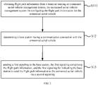
- FIG. 2 is a flow chart illustrating another method for configuring a flight path according to exemplary embodiments of the disclosure. As illustrated in FIG. 2 , on the basis of embodiments illustrated in FIG. 1 , obtaining the flight path information of the unmanned aerial vehicle includes the following.
- the flight path information is obtained from a terminal running an unmanned aerial-vehicle management system.
- the unmanned aerial-vehicle management system is configured to configure the flight path information for the unmanned aerial vehicle.
- the flight path information may be configured by the unmanned aerial-vehicle management system.
- the unmanned aerial-vehicle management system may run on the terminal. There may be the communication connection between the core network and the terminal, such that the flight path information of the unmanned aerial vehicle may be obtained from the terminal.
- the terminal running the unmanned aerial-vehicle management system may be a device such as a server or a remote controller.
- the first signaling includes at least one of: an initial context setup request, and a user equipment (UE) context modification request.
- UE user equipment
- the core network may send different first signaling to the base station based on a relationship between a timing of obtaining the flight path information and a connection state of the unmanned aerial vehicle and the base station, which may be described in detail in following embodiments.
- FIG. 3 is a flow chart illustrating another method for configuring a flight path according to exemplary embodiments of the disclosure. As illustrated in FIG. 3 , on the basis of embodiments illustrated in FIG. 1 , sending the first signaling to the base station includes the following.
- the initial context setup request is sent to the base station under a case that the flight path information has been obtained when a communication connection is established initially with the unmanned aerial vehicle through the base station.
- the configuration of the flight path for the unmanned aerial vehicle may be regarded as an initial configuration, such that the initial context setup request may be sent to the base station, and the flight path information may be carried in the initial context setup request.
- formats of the initial context setup request may be illustrated as Table 1.
- Table 1 IE/Group Name Presence Range IE type and reference Semantics description Criticality Assigned Criticality Message Type M 9.2.1.1 YES reject MME UE S1AP ID M 9.2.3.3 YES reject eNB UE S1AP ID M 9.2.3.4 YES reject --- --- --- --- --- --- --- --- --- UE Sidelink Aggregate Maximum Bit Rate O 9.2.1.122 This IE applies only if the UE is authorized for V2X services.
- YES ignore Enhanced Coverage Restricted O 9.2.1.123 YES ignore NR UE Security Capabilities
- the core network may send the initial context setup request to the base station via an S1 access point.
- the Flight Path Information in the initial context setup request is the flight path information.
- FIG. 4 is a flow chart illustrating another method for configuring a flight path according to exemplary embodiments of the disclosure. As illustrated in FIG. 4 , on the basis of embodiments illustrated in FIG. 1 , sending the first signaling to the base station includes the following.
- the flight path information is obtained and the UE context modification request is sent to the base station under a case that a communication connection with the unmanned aerial vehicle has been established through the base station.
- the core network has established the communication connection between the unmanned aerial vehicle through the base station.
- the flight path information is obtained.
- the configuration of the flight path for the unmanned aerial vehicle may be regarded as the initial configuration, such that the initial context setup request may be sent to the base station, and the flight path information may be carried in the initial context setup request.
- formats of the UE context modification request may be illustrated as Table 2.
- Table 2 IE/Group Name Presence Range IE type and reference Semantics description Criticality Assigned Criticality Message Type M 9.2.1.1 YES reject MME UE S1AP ID M 9.2.3.3 YES reject eNB UE S1AP ID M 9.2.3.4 YES reject UE Sidelink Aggregate Maximum Bit Rate O 9.2.1.122 This IE applies only if the UE is authorized for V2X services.
- YES ignore NR UE Security Capabilities O 9.2.1.127 YES ignore Flight Path Information O 9.2.x.x YES ignore
- the core network may send the UE context modification request to the base station via the S1 access point.
- the Flight Path Information in the UE context modification request is the flight path information.
- the second signaling includes at least one of: a radio resource control signaling, and a media access control MAC control element CE.
- the core network may indicate the base station by the first signaling to send the flight path information to the unmanned aerial vehicle via the RRC (radio resource control) signaling or via the MAC CE.
- Away for sending the flight path information carried in the RRC signaling or in the MAC CE to the unmanned aerial vehicle may be selected based on a requirement.
- FIG. 5 is a flow chart illustrating another method for configuring a flight path according to exemplary embodiments of the disclosure.
- the method for configuring the flight path illustrated in embodiments may be applicable to a base station.
- the base station may communicate with a core network.
- the base station may communicate with a user device.
- the user device may be an unmanned aerial vehicle.
- the unmanned aerial vehicle may be an unmanned aircraft, an unmanned airship or the like.
- a communication between the base station and the user device may be based on a LTE or an NR
- the method for configuring the flight path includes the following.
- a first signaling is received from a core network.
- the first signaling includes flight path information of an unmanned aerial vehicle.
- the first signaling is configured to indicate the base station to send the flight path information to the unmanned aerial vehicle via a second signaling.
- the unmanned aerial vehicle is in a connection state.
- the second signaling is generated based on the first signaling.
- the second signaling is sent to the unmanned aerial vehicle.
- the second signaling includes the flight path information.
- the base station may directly send the flight path information to the unmanned aerial vehicle having the communication connection with the base station.
- the core network may first determine the base station having the communication connection with the unmanned aerial vehicle, send the first signaling including the flight path information to the determined base station, and indicate the base station by the first signaling to send the flight path information via the second signaling to the unmanned aerial vehicle.
- the base station may generate the second signaling including the flight path information after receiving the first signaling, and send the second signaling to the unmanned aerial vehicle.
- the flight path information is sent from the core network to the unmanned aerial vehicle in the connection state, such that the unmanned aerial vehicle may configure the flight path based on the flight path information.
- the configuration of the flight path may be completed based on a network of a telecom operator without establishing a proprietary link, and the configuration process is relatively simple.
- the second signaling includes at least one of: a radio resource control signaling, and a media access control MAC control element CE.
- the base station may send the flight path information to the unmanned aerial vehicle via the radio resource control signaling or the MAC CE based on the first signaling sent by the core network.
- Away for sending the flight path information carried in the RRC signaling or in the MAC CE to unmanned aerial vehicle may be selected based on a requirement.
- FIG. 6 is a flow chart illustrating another method for configuring a flight path according to exemplary embodiments of the disclosure.
- the method for configuring the flight path illustrated in embodiments may be applicable to an unmanned aerial vehicle.
- the unmanned aerial vehicle may be an unmanned aircraft, an unmanned airship or the like.
- a communication between the base station and the unmanned aerial vehicle may be based on a LTE or an NR
- the method for configuring the flight path includes the following.
- a second signaling is received from a base station.
- the second signaling is generated by the base station based on a first signaling sent by a core network.
- the first signaling includes flight path information of the unmanned aerial vehicle.
- the first signaling is configured to indicate the base station to send the flight path information to the unmanned aerial vehicle via the second signaling.
- the unmanned aerial vehicle is in a connection state.
- the flight path information is extracted from the second signaling.
- the flight path is configured based on the flight path information.
- the base station may directly send the flight path information to the unmanned aerial vehicle having the communication connection with the base station.
- the core network may first determine the base station having the communication connection with the unmanned aerial vehicle, send the first signaling including the flight path information to the determined base station, and indicate the base station by the first signaling to send the flight path information via the second signaling to the unmanned aerial vehicle.
- the base station may generate the second signaling including the flight path information after receiving the first signaling, and send the second signaling to the unmanned aerial vehicle.
- the flight path information is sent from the core network to the unmanned aerial vehicle in the connection state, such that the unmanned aerial vehicle may configure the flight path based on the flight path information after receiving the flight path information.
- the configuration of the flight path may be completed based on a network of a telecom operator without establishing a proprietary link, and the configuration process is relatively simple.
- the second signaling includes at least one of: a radio resource control signaling, and a media access control MAC control element CE.
- the base station may send the flight path information to the unmanned aerial vehicle via the radio resource control signaling or the MAC CE based on the first signaling sent by the core network.
- the unmanned aerial vehicle may obtain the flight path information by receiving the radio resource control signaling or the MAC CE.
- the way for obtaining the flight path information by receiving the radio resource control signaling or the MAC CE may be selected based on a signaling sent by the base station.
- FIG. 7 is a schematic diagram illustrating an interaction among a core network, a base station and an unmanned aerial vehicle according to exemplary embodiments of the disclosure.
- a core network may send a first signaling to a base station having a communication connection with the unmanned aerial vehicle.
- the first signaling includes the flight path information.
- the base station may be indicated by the first signaling to send the flight path information to the unmanned aerial vehicle via a second signaling.
- the base station may generate the second signaling based on the first signaling after receiving the first signaling.
- the second signaling includes the flight path information.
- the base station sends the flight path information to the unmanned aerial vehicle via the second signaling.
- the base station may directionally send the second signaling to the unmanned aerial vehicle since there is the communication connection between the base station and the unmanned aerial vehicle.
- the unmanned aerial vehicle may obtain the flight path information after receiving the second signaling, and configure the flight path based on the flight path information, thereby flying based on the configured flight path.
- the disclosure also provides embodiments of an apparatus for configuring the flight path.
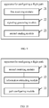
- FIG. 8 is a block diagram illustrating an apparatus for configuring a flight path according to exemplary embodiments of the disclosure.
- the apparatus for configuring the flight path illustrated in embodiments may be applicable to a core network.
- the core network may communicate with a base station.
- the base station may communicate with a user device.
- the user device may be an unmanned aerial vehicle.
- the unmanned aerial vehicle may be an unmanned aircraft, an unmanned airship or the like.
- a communication between the base station and the user device may be based on a long term evolution (LTE) or a new radio (NR).
- LTE long term evolution
- NR new radio
- the apparatus for configuring the flight path includes an information obtaining module 11, a base station determining module 12, and a first sending module 13.
- the information obtaining module 11 is configured to obtain flight path information of an unmanned aerial vehicle.
- the unmanned aerial vehicle is in a connection state.
- the base station determining module 12 is configured to determine a base station having a communication connection with the unmanned aerial vehicle.
- the first sending module 13 is configured to send a first signaling to the base station.
- the first signaling includes the flight path information.
- the first signaling is configured to indicate the base station to send the flight path information to the unmanned aerial vehicle via a second signaling.
- the information obtaining module 11 is configured to: obtain the flight path information from a terminal running an unmanned aerial-vehicle management system.
- the unmanned aerial-vehicle management system is configured to configure the flight path information for the unmanned aerial vehicle.
- the first signaling includes at least one of: an initial context setup request and a user equipment UE context modification request.
- the signaling sending module is configured to: send the initial context setup request to the base station under a case that the flight path information has been obtained when a communication connection is established initially with the unmanned aerial vehicle through the base station.
- the signaling sending module is configured to: obtain the flight path information and send the UE context modification request to the base station under a case that a communication connection with the unmanned aerial vehicle has been established through the base station.
- the second signaling includes at least one of: a radio resource control signaling, and a media access control MAC control element CE.
- FIG. 9 is a block diagram illustrating another apparatus for configuring a flight path according to exemplary embodiments of the disclosure.
- the apparatus for configuring the flight path illustrated in embodiments may be applicable to a base station.
- the base station may communicate with a core network.
- the base station may communicate with a user device.
- the user device may be an unmanned aerial vehicle.
- the unmanned aerial vehicle may be an unmanned aircraft, an unmanned airship or the like.
- a communication between the base station and the user device may be based on a LTE or an NR
- the apparatus for configuring the flight path includes: a first receiving module 21, a signaling generating module 22, and a second sending module 23.
- the first receiving module 21 is configured to receive a first signaling from a core network.
- the first signaling includes flight path information of an unmanned aerial vehicle.
- the first signaling is configured to indicate the base station to send the flight path information to the unmanned aerial vehicle via a second signaling.
- the unmanned aerial vehicle is in a connection state.
- the signaling generating module 22 is configured to generate the second signaling based on the first signaling.
- the second sending module 23 is configured to send the second signaling to the unmanned aerial vehicle.
- the second signaling includes the flight path information.
- the second signaling includes at least one of: a radio resource control signaling, and a media access control MAC control element CE.
- FIG. 10 is a block diagram illustrating another apparatus for configuring a flight path according to exemplary embodiments of the disclosure.
- the apparatus for configuring the flight path illustrated in embodiments may be applicable to an unmanned aerial vehicle.
- the unmanned aerial vehicle may be an unmanned aircraft, an unmanned airship or the like.
- a communication between the base station and the unmanned aerial vehicle may be based on a LTE or an NR
- the apparatus for configuring the flight path includes: a second receiving module 31, an information extracting module 32, and a path configuring module 33.
- the second receiving module 31 is configured to receive a second signaling from a base station.
- the second signaling is generated by the base station based on a first signaling sent by a core network.
- the first signaling includes flight path information of an unmanned aerial vehicle.
- the first signaling is configured to indicate the base station to send the flight path information to the unmanned aerial vehicle via the second signaling.
- the unmanned aerial vehicle is in a connection state.
- the information extracting module 32 is configured to extract the flight path information from the second signaling.
- the path configuring module 33 is configured to configure the flight path based on the flight path information.
- the second signaling includes at least one of: a radio resource control signaling, and a media access control MAC control element CE.
- the apparatus embodiments basically correspond to the method embodiments. Therefore, the relevant part of the apparatus embodiments may refer to the description of the method embodiments.
- the apparatus embodiments described above are only illustrative.
- the units described as separate components may or may not be physically separated, and the components illustrated as units may or may not be physical units. That is, the components or units may be located in one place or distributed to multiple network units. A part or all of the modules may be selected based on an actual requirement to achieve the purpose of embodiments of the disclosure.
- the skilled in the art may understand and implement embodiments of the disclosure without any creative labor.
- Embodiments of the disclosure also provide an electronic device.
- the electronic device includes: a processor and a memory.
- the memory is configured to store instructions executable by the processor.
- the processor is configured to implement the method according to any one of the above embodiments.
- Embodiments of the disclosure also provide a computer-readable storage medium having a computer program stored thereon.
- the computer program is configured to implement the method according to any one of the above embodiments when executed by a processor.
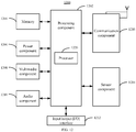
- FIG. 11 is a block diagram illustrating a device 1100 for configuring a flight path according to exemplary embodiments of the disclosure.
- the device 1100 may be provided as a base station. With reference to FIG. 11 .
- the device 1100 includes a processing component 1122, a wireless transmitting/receiving component 1124, an antenna component 1126, and a signal processing part specific to a wireless interface.
- the processing component 1122 may further include one or more processors. One of the one or more processors in the processing component 1122 may be configured to implement the method according to any one of the above embodiments.
- FIG. 12 is a block diagram illustrating a device 1200 for configuring a flight path according to exemplary embodiments of the disclosure.
- the device 1200 may be a mobile phone, a computer, a digital broadcasting terminal, a message sending and receiving equipment, a game controller, a tablet device, a medical device, a fitness equipment, a personal digital assistant or the like.
- the device 1200 may include one or more of: a processing component 1202, a memory 1204, a power component 1206, a multimedia component 1208, an audio component 1210, an input/output (I/O) interface 1212, a sensor component 1214, and a communication component 1216.
- a processing component 1202 a memory 1204, a power component 1206, a multimedia component 1208, an audio component 1210, an input/output (I/O) interface 1212, a sensor component 1214, and a communication component 1216.
- the processing component 1202 typically controls overall operations of the device 1200, such as the operations associated with display, telephone calls, data communications, camera operations, and recording operations.
- the processing component 1202 may include one or more processors 1220 to execute instructions to perform all or part of the steps in the above described methods.
- the processing component 1202 may include one or more modules which facilitate the interaction between the processing component 1202 and other components.
- the processing component 1202 may include a multimedia module to facilitate the interaction between the multimedia component 1208 and the processing component 1202.
- the memory 1204 is configured to store various types of data to support the operation of the device 1200. Examples of such data include instructions for any applications or methods operated on the device 1200 for performing the directional operation, contraction data, phonebook data, messages, pictures, video, etc.
- the memory 1204 may be implemented using any type of volatile or non-volatile memory devices, or a combination thereof, such as a static random access memory (SRAM), an electrically erasable programmable read-only memory (EEPROM), an erasable programmable read-only memory (EPROM), a programmable read-only memory (PROM), a read-only memory (ROM), a magnetic memory, a flash memory, a magnetic or optical disk.
- SRAM static random access memory
- EEPROM electrically erasable programmable read-only memory
- EPROM erasable programmable read-only memory
- PROM programmable read-only memory
- ROM read-only memory
- magnetic memory a magnetic memory
- flash memory a flash memory
- the power component 1206 is configured to provide power to various components of the device 1200.
- the power component 1206 may include a power management system, one or more power sources, and any other components associated with the generation, management, and distribution of power in the device 1200.
- the multimedia component 1208 includes a screen providing an output interface between the device 1200 and the user.
- the screen may include a liquid crystal display (LCD) and a touch panel (TP). If the screen includes the touch panel, the screen may be implemented as a touch screen to receive input signals from the user.
- the touch panel includes one or more touch sensors to sense touches, swipes, and gestures on the touch panel. The touch sensors may not only sense a boundary of a touch or swipe action, but also sense a period of time and a pressure associated with the touch or swipe action.
- the multimedia component 1208 includes a front camera and/or a rear camera. The front camera and the rear camera may receive an external multimedia datum while the device 1200 is in an operation mode, such as an adjustment mode or a video mode. Each of the front camera and the rear camera may be a fixed optical lens system or have focus and optical zoom capability.
- the audio component 1210 is configured to output and/or input audio signals.
- the audio component 1210 includes a microphone ("MIC") for receiving an external audio signal when the device 1200 is in an operation mode, such as a call mode, a recording mode, and a voice recognition mode.
- the received audio signal may be further stored in the memory 1204 or transmitted via the communication component 1216.
- the audio component 1210 further includes a speaker to output audio signals.
- the I/O interface 1212 is configured to provide an interface between the processing component 1202 and peripheral interface modules, such as a keyboard, a click wheel, buttons, and the like.
- the buttons may include, but be not limited to, a home button, a volume button, a starting button, and a locking button.
- the sensor component 1214 includes one or more sensors for providing status assessments of various aspects of the device 1200.
- the sensor component 1214 may detect an open/closed status of the device 1200, relative positioning of components, e.g., the display and the keypad of the device 1200, a change in position of the device 1200 or a component of the device 1200, a presence or absence of user contraction with the device 1200, an orientation or an acceleration/deceleration of the device 1200, and a change in temperature of the device 1200.
- the sensor component 1214 may include a proximity sensor for detecting the presence of nearby objects without any physical contact.
- the sensor component 1214 may also include a light sensor, such as a CMOS (complementary metal-oxide-semiconductor)) or a CCD (charge coupled device) image sensor, for use in imaging applications.
- CMOS complementary metal-oxide-semiconductor
- CCD charge coupled device
- the sensor component 1214 may also include an accelerometer sensor, a gyroscope sensor, a magnetic sensor, a pressure sensor, or a temperature sensor.
- the communication component 1216 is configured to facilitate communication, wired or wirelessly, between the device 1200 and other devices.
- the device 1200 may access a wireless network based on a communication standard, such as Wi-Fi, 2G, or 3G, or a combination thereof.
- the communication component 1216 receives a broadcast signal or broadcast associated information from an external broadcast management system via a broadcast channel.
- the communication component 1216 further includes a near field communication (NFC) module to facilitate short-range communications.
- the NFC module may be implemented based on a radio frequency identification (RFID) technology, an infrared data association (IrDA) technology, an ultra-wideband (UWB) technology, a Bluetooth (BT) technology, and other technologies.
- RFID radio frequency identification
- IrDA infrared data association
- UWB ultra-wideband
- BT Bluetooth
- the device 1200 may be implemented with one or more application specific integrated circuits (ASICs), digital signal processors (DSPs), digital signal processing devices (DSPDs), programmable logic devices (PLDs), field programmable gate arrays (FPGAs), controllers, micro-controllers, microprocessors, or other electronic components, for performing the above methods.
- ASICs application specific integrated circuits
- DSPs digital signal processors
- DSPDs digital signal processing devices
- PLDs programmable logic devices
- FPGAs field programmable gate arrays
- controllers micro-controllers, microprocessors, or other electronic components, for performing the above methods.
- non-transitory computer-readable storage medium including instructions, such as the memory 1204 including the instructions.
- the instruction may be executed by the processor 1220 in the device 1200 for performing the above method.
- the non-transitory computer-readable storage medium may be a ROM, a RAM, a CD-ROM, a magnetic tape, a floppy disc, an optical data storage device, and the like.
Landscapes
- Engineering & Computer Science (AREA)
- Aviation & Aerospace Engineering (AREA)
- Physics & Mathematics (AREA)
- General Physics & Mathematics (AREA)
- Computer Networks & Wireless Communication (AREA)
- Signal Processing (AREA)
- Radar, Positioning & Navigation (AREA)
- Remote Sensing (AREA)
- Automation & Control Theory (AREA)
- Astronomy & Astrophysics (AREA)
- Mobile Radio Communication Systems (AREA)
Abstract
Description
- The disclosure relates to the field of communication technologies, and more particularly to a method for configuring a flight path, an apparatus for configuring a flight path, an electronic device, and a computer-readable storage medium.
- In the related art, when a flight path is configured for an unmanned aerial vehicle, flight path information needs to be sent to the unmanned aerial vehicle via a proprietary link. For example, the flight path information is sent to the unmanned aerial vehicle via a Wi-Fi (wireless fidelity) connection with the unmanned aerial vehicle or via a satellite forwarding way.
- Presently, such ways for configuring the flight path for the unmanned aerial vehicle need to establish the proprietary link, and a configuration process is cumbersome.
- For this, embodiments of the disclosure provide a method for configuring a flight path, an apparatus for configuring a flight path, an electronic device, and a computer-readable storage medium.
- According to a first aspect of embodiments of the disclosure, there is provided a method for configuring a flight path. The method includes: obtaining flight path information of an unmanned aerial vehicle, the unmanned aerial vehicle being in a connection state; determining a base station having a communication connection with the unmanned aerial vehicle; and sending a first signaling to the base station, the first signaling including the flight path information, and the first signaling for indicating the base station to send the flight path information to the unmanned aerial vehicle via a second signaling.
- Alternatively, obtaining the flight path information of the unmanned aerial vehicle includes: obtaining the flight path information from a terminal running an unmanned aerial-vehicle management system, the unmanned aerial-vehicle management system for configuring the flight path information for the unmanned aerial vehicle.
- Alternatively, the first signaling includes at least one of: an initial context setup request, and a user equipment UE context modification request.
- Alternatively, sending the first signaling to the base station includes: sending the initial context setup request to the base station under a case that the flight path information has been obtained when a communication connection is established initially with the unmanned aerial vehicle through the base station.
- Alternatively, sending the first signaling to the base station includes: obtaining the flight path information and sending the UE context modification request to the base station under a case that a communication connection with the unmanned aerial vehicle has been established through the base station.
- Alternatively, the second signaling includes at least one of: a radio resource control signaling, and a media access control MAC control element CE.
- According to a second aspect of embodiments of the disclosure, there is provided a method for configuring a flight path. The method includes: receiving a first signaling from a core network, the first signaling including flight path information of an unmanned aerial vehicle, the first signaling for indicating a base station to send the flight path information to the unmanned aerial vehicle via a second signaling, and the unmanned aerial vehicle being in a connection state; generating the second signaling based on the first signaling; and sending the second signaling to the unmanned aerial vehicle, the second signaling including the flight path information.
- Alternatively, the second signaling includes at least one of: a radio resource control signaling, and a media access control MAC control element CE.
- According to a third aspect of embodiments of the disclosure, there is provided a method for configuring a flight path. The method includes: receiving a second signaling from a base station, the second signaling being generated by the base station based on a first signaling sent by a core network, the first signaling including flight path information of an unmanned aerial vehicle, the first signaling for indicating the base station to send the flight path information to the unmanned aerial vehicle via the second signaling, and the unmanned aerial vehicle being in a connection state; extracting the flight path information from the second signaling; and configuring the flight path based on the flight path information.
- Alternatively, the second signaling includes at least one of: a radio resource control signaling, and a media access control MAC control element CE.
- According to a fourth aspect of embodiments of the disclosure, there is provided an apparatus for configuring a flight path. The apparatus includes: an information obtaining module, a base station determining module, and a first sending module. The information obtaining module is configured to obtain flight path information of an unmanned aerial vehicle. The unmanned aerial vehicle is in a connection state. The base station determining module is configured to determine a base station having a communication connection with the unmanned aerial vehicle. The first sending module is configured to send a first signaling to the base station. The first signaling includes the flight path information. The first signaling is configured to indicate the base station to send the flight path information to the unmanned aerial vehicle via a second signaling.
- Alternatively, the information obtaining module is configured to: obtain the flight path information from a terminal running an unmanned aerial-vehicle management system. The unmanned aerial-vehicle management system is configured to configure the flight path information for the unmanned aerial vehicle.
- Alternatively, the first signaling includes at least one of: an initial context setup request and a user equipment UE context modification request.
- Alternatively, the signaling sending module is configured to: send the initial context setup request to the base station under a case that the flight path information has been obtained when a communication connection is established initially with the unmanned aerial vehicle through the base station.
- Alternatively, signaling signaling sending module is configured to: obtain the flight path information and send the UE context modification request to the base station under a case that a communication connection with the unmanned aerial vehicle has been established through the base station.
- Alternatively, the second signaling includes at least one of: a radio resource control signaling, and a media access control MAC control element CE.
- According to a fifth aspect of embodiments of the disclosure, there is provided an apparatus for configuring a flight path. The apparatus includes: a first receiving module, a signaling generating module, and a second sending module. The first receiving module is configured to receive a first signaling from a core network. The first signaling includes flight path information of an unmanned aerial vehicle. The first signaling is configured to indicate a base station to send the flight path information to the unmanned aerial vehicle via a second signaling. The unmanned aerial vehicle is in a connection state. The signaling generating module is configured to generate the second signaling based on the first signaling. The second sending module is configured to send the second signaling to the unmanned aerial vehicle. The second signaling includes the flight path information.
- Alternatively, the second signaling includes at least one of: a radio resource control signaling, and a media access control MAC control element CE.
- According to a sixth aspect of embodiments of the disclosure, there is provided an apparatus for configuring a flight path. The apparatus includes: a second receiving module, an information extracting module, and a path configuring module. The second receiving module is configured to receive a second signaling from a base station. The second signaling is generated by the base station based on a first signaling sent by a core network. The first signaling includes flight path information of an unmanned aerial vehicle. The first signaling is configured to indicate the base station to send the flight path information to the unmanned aerial vehicle via the second signaling. The unmanned aerial vehicle is in a connection state. The information extracting module is configured to extract the flight path information from the second signaling. The path configuring module is configured to configure the flight path based on the flight path information.
- Alternatively, the second signaling includes at least one of: a radio resource control signaling, and a media access control MAC control element CE.
- According to a fifth aspect of embodiments of the disclosure, there is provided an electronic device. The electronic device includes: a processor and a memory. The memory is configured to store instructions executable by the processor. The processor is configured to implement the method according to any one of the above embodiments.
- According to a sixth aspect of embodiments of the disclosure, there is provided a computer-readable storage medium having a computer program stored thereon. The computer program is configured to implement the method according to any one of the above embodiments when executed by a processor.
- According to embodiments of the disclosure, for the unmanned aerial vehicle in the connection state, since there is the communication connection between the unmanned aerial vehicle and the base station, the flight path information from the core network may be directly sent to the unmanned aerial vehicle through the base station. Therefore, the base station having the communication connection with the unmanned aerial vehicle may be determined first, and then the first signaling including the flight path information may be sent to the base station having the communication connection with the unmanned aerial vehicle. The base station is indicated by the first signaling to send the flight path information to the unmanned aerial vehicle via the second signaling. In this way, it is implemented that the flight path information may be sent from the core network to the unmanned aerial vehicle in the connection state, such that the unmanned aerial vehicle configures the flight path based on the flight path information. Comparing with the related art, the configuration of the flight path may be completed based on a network of a telecom operator without establishing a proprietary link, and a configuration process is relatively simple.
- In order to describe the technical solution in embodiments of the disclosure more clearly, a brief introduction will be made below to accompanying drawings required in the description of embodiments. Obviously, the accompanying drawings in the following description are only a part of embodiments of the disclosure. For the skilled in the art, other accompanying drawings may be obtained based on these accompanying drawings without paying creative labor.
-
FIG. 1 is a flow chart illustrating a method for configuring a flight path according to exemplary embodiments of the disclosure. -
FIG. 2 is a flow chart illustrating another method for configuring a flight path according to exemplary embodiments of the disclosure. -
FIG. 3 is a flow chart illustrating another method for configuring a flight path according to exemplary embodiments of the disclosure. -
FIG. 4 is a flow chart illustrating another method for configuring a flight path according to exemplary embodiments of the disclosure. -
FIG. 5 is a flow chart illustrating another method for configuring a flight path according to exemplary embodiments of the disclosure. -
FIG. 6 is a flow chart illustrating another method for configuring a flight path according to exemplary embodiments of the disclosure. -
FIG. 7 is a schematic diagram illustrating an interaction among a core network, a base station and an unmanned aerial vehicle according to exemplary embodiments of the disclosure. -
FIG. 8 is a block diagram illustrating an apparatus for configuring a flight path according to exemplary embodiments of the disclosure. -
FIG. 9 is a block diagram illustrating another apparatus for configuring a flight path according to exemplary embodiments of the disclosure. -
FIG. 10 is a block diagram illustrating another apparatus for configuring a flight path according to exemplary embodiments of the disclosure. -
FIG. 11 is a block diagram illustrating a device for configuring a flight path according to exemplary embodiments of the disclosure. -
FIG. 12 is a block diagram illustrating a device for configuring a flight path according to exemplary embodiments of the disclosure. - Description will be made clearly and completely below to the technical solution in embodiments of the disclosure with reference to the accompanying drawings in embodiments of the disclosure. Obviously, the described embodiments are only a part of embodiments of the disclosure, but not all the embodiments. Based on embodiments in the disclosure, all other embodiments obtained by the skilled in the art without creative labor belong to the protection scope of the disclosure.
-
FIG. 1 is a flow chart illustrating a method for configuring a flight path according to exemplary embodiments of the disclosure. The method for configuring the flight path illustrated in embodiments may be applicable to a core network. The core network may communicate with a base station. The base station may communicate with a user device. The user device may be an unmanned aerial vehicle. The unmanned aerial vehicle may be an unmanned aircraft, an unmanned airship or the like. A communication between the base station and the user device may be based on a long term evolution (LTE) or a new radio (NR). - As illustrated in
FIG. 1 , the method for configuring the flight path includes the following. - At
block S 11, flight path information of an unmanned aerial vehicle is obtained. The unmanned aerial vehicle is in a connection state. - In some embodiments, the flight path information may be configured by an unmanned aerial-vehicle management system. The unmanned aerial-vehicle management system may be, such as, a UTM (UAS traffic management). The UAS is the abbreviation of the unmanned aircraft system. The unmanned aerial-vehicle management system may run on a terminal. There may be a communication connection between the core network and the terminal, such that the flight path information of the unmanned aerial vehicle may be obtained from the terminal.
- In some embodiments, the unmanned aerial vehicle is in the connection state, which means that there is a communication connection between the unmanned aerial vehicle and the base station. Since there is a communication connection between the base station and the core network, the core network may determine whether the communication connection between the unmanned aerial vehicle and the base station is disconnected. For example, when there is data transmission between the unmanned aerial vehicle and the base station, it may be determined that there is the communication connection between the unmanned aerial vehicle and the base station, that is, the unmanned aerial vehicle is in the connection state. When there is no data transmission between the unmanned aerial vehicle and the base station, it may be determined that the unmanned aerial vehicle is disconnected from the base station.
- At block S12, a base station having a communication connection with the unmanned aerial vehicle is determined.
- In some embodiments, since the unmanned aerial vehicle is in the connection state, and there is the communication connection between the base station and the core network, the core network may determine which base station has the communication connection with the unmanned aerial vehicle, thereby facilitating to subsequently send the flight path information to the unmanned aerial vehicle through the base station.
- At block S13, a first signaling is sent to the base station. The first signaling includes the flight path information, and the first signaling is configured to indicate the base station to send the flight path information to the unmanned aerial vehicle via a second signaling.
- In some embodiments, for the unmanned aerial vehicle in the connection state, since there is the communication connection between the unmanned aerial vehicle and the base station, the flight path information from the core network may be directly sent to the unmanned aerial vehicle through the base station. Therefore, the base station having the communication connection with the unmanned aerial vehicle may be determined first, and then the first signaling including the flight path information may be sent to the base station having the communication connection with the unmanned aerial vehicle. The base station is indicated by the first signaling to send the flight path information to the unmanned aerial vehicle via the second signaling. In this way, it is implemented that the flight path information may be sent from the core network to the unmanned aerial vehicle in the connection state, such that the unmanned aerial vehicle configures the flight path based on the flight path information. Comparing with the related art, the configuration of the flight path may be completed based on a network of a telecom operator without establishing a proprietary link, and a configuration process is relatively simple.
-
FIG. 2 is a flow chart illustrating another method for configuring a flight path according to exemplary embodiments of the disclosure. As illustrated inFIG. 2 , on the basis of embodiments illustrated inFIG. 1 , obtaining the flight path information of the unmanned aerial vehicle includes the following. - At block S111, the flight path information is obtained from a terminal running an unmanned aerial-vehicle management system. The unmanned aerial-vehicle management system is configured to configure the flight path information for the unmanned aerial vehicle.
- In some embodiments, the flight path information may be configured by the unmanned aerial-vehicle management system. The unmanned aerial-vehicle management system may run on the terminal. There may be the communication connection between the core network and the terminal, such that the flight path information of the unmanned aerial vehicle may be obtained from the terminal.
- The terminal running the unmanned aerial-vehicle management system may be a device such as a server or a remote controller.
- Alternatively, the first signaling includes at least one of: an initial context setup request, and a user equipment (UE) context modification request.
- In some embodiments, the core network may send different first signaling to the base station based on a relationship between a timing of obtaining the flight path information and a connection state of the unmanned aerial vehicle and the base station, which may be described in detail in following embodiments.
-
FIG. 3 is a flow chart illustrating another method for configuring a flight path according to exemplary embodiments of the disclosure. As illustrated inFIG. 3 , on the basis of embodiments illustrated inFIG. 1 , sending the first signaling to the base station includes the following. - At block S131, the initial context setup request is sent to the base station under a case that the flight path information has been obtained when a communication connection is established initially with the unmanned aerial vehicle through the base station.
- In some embodiments, under a case that the core network obtains the flight path information when initially establishing the communication connection with the unmanned aerial vehicle through the base station, the configuration of the flight path for the unmanned aerial vehicle may be regarded as an initial configuration, such that the initial context setup request may be sent to the base station, and the flight path information may be carried in the initial context setup request.
- In some embodiments, formats of the initial context setup request may be illustrated as Table 1.
Table 1 IE/Group Name Presence Range IE type and reference Semantics description Criticality Assigned Criticality Message Type M 9.2.1.1 YES reject MME UE S1AP ID M 9.2.3.3 YES reject eNB UE S1AP ID M 9.2.3.4 YES reject --- --- --- --- --- --- --- UE Sidelink Aggregate Maximum Bit Rate O 9.2.1.122 This IE applies only if the UE is authorized for V2X services. YES ignore Enhanced Coverage Restricted O 9.2.1.123 YES ignore NR UE Security Capabilities O 9.2.1.127 YES ignore Flight Path Information O 9.2.x.x YES ignore - The core network may send the initial context setup request to the base station via an S1 access point. The Flight Path Information in the initial context setup request is the flight path information.
-
FIG. 4 is a flow chart illustrating another method for configuring a flight path according to exemplary embodiments of the disclosure. As illustrated inFIG. 4 , on the basis of embodiments illustrated inFIG. 1 , sending the first signaling to the base station includes the following. - At block S132, the flight path information is obtained and the UE context modification request is sent to the base station under a case that a communication connection with the unmanned aerial vehicle has been established through the base station.
- In some embodiments, the core network has established the communication connection between the unmanned aerial vehicle through the base station. In this case, the flight path information is obtained. The configuration of the flight path for the unmanned aerial vehicle may be regarded as the initial configuration, such that the initial context setup request may be sent to the base station, and the flight path information may be carried in the initial context setup request.
- In some embodiments, formats of the UE context modification request may be illustrated as Table 2.
Table 2 IE/Group Name Presence Range IE type and reference Semantics description Criticality Assigned Criticality Message Type M 9.2.1.1 YES reject MME UE S1AP ID M 9.2.3.3 YES reject eNB UE S1AP ID M 9.2.3.4 YES reject UE Sidelink Aggregate Maximum Bit Rate O 9.2.1.122 This IE applies only if the UE is authorized for V2X services. YES ignore NR UE Security Capabilities O 9.2.1.127 YES ignore Flight Path Information O 9.2.x.x YES ignore - The core network may send the UE context modification request to the base station via the S1 access point. The Flight Path Information in the UE context modification request is the flight path information.
- Alternatively, the second signaling includes at least one of: a radio resource control signaling, and a media access control MAC control element CE.
- In some embodiments, the core network may indicate the base station by the first signaling to send the flight path information to the unmanned aerial vehicle via the RRC (radio resource control) signaling or via the MAC CE. Away for sending the flight path information carried in the RRC signaling or in the MAC CE to the unmanned aerial vehicle may be selected based on a requirement.
-
FIG. 5 is a flow chart illustrating another method for configuring a flight path according to exemplary embodiments of the disclosure. The method for configuring the flight path illustrated in embodiments may be applicable to a base station. The base station may communicate with a core network. The base station may communicate with a user device. The user device may be an unmanned aerial vehicle. The unmanned aerial vehicle may be an unmanned aircraft, an unmanned airship or the like. A communication between the base station and the user device may be based on a LTE or an NR - As illustrated in
FIG. 5 , the method for configuring the flight path includes the following. - At block S21, a first signaling is received from a core network. The first signaling includes flight path information of an unmanned aerial vehicle. The first signaling is configured to indicate the base station to send the flight path information to the unmanned aerial vehicle via a second signaling. The unmanned aerial vehicle is in a connection state.
- At block S22, the second signaling is generated based on the first signaling.
- At block S23, the second signaling is sent to the unmanned aerial vehicle. The second signaling includes the flight path information.
- In some embodiments, for the unmanned aerial vehicle in the connection state, since there is a communication connection between the unmanned aerial vehicle and the base station, after receiving the flight path information sent by the core network, the base station may directly send the flight path information to the unmanned aerial vehicle having the communication connection with the base station.
- Therefore, the core network may first determine the base station having the communication connection with the unmanned aerial vehicle, send the first signaling including the flight path information to the determined base station, and indicate the base station by the first signaling to send the flight path information via the second signaling to the unmanned aerial vehicle. The base station may generate the second signaling including the flight path information after receiving the first signaling, and send the second signaling to the unmanned aerial vehicle. In this way, it is implemented that the flight path information is sent from the core network to the unmanned aerial vehicle in the connection state, such that the unmanned aerial vehicle may configure the flight path based on the flight path information. Comparing with the related art, the configuration of the flight path may be completed based on a network of a telecom operator without establishing a proprietary link, and the configuration process is relatively simple.
- Alternatively, the second signaling includes at least one of: a radio resource control signaling, and a media access control MAC control element CE.
- In some embodiments, the base station may send the flight path information to the unmanned aerial vehicle via the radio resource control signaling or the MAC CE based on the first signaling sent by the core network. Away for sending the flight path information carried in the RRC signaling or in the MAC CE to unmanned aerial vehicle may be selected based on a requirement.
-
FIG. 6 is a flow chart illustrating another method for configuring a flight path according to exemplary embodiments of the disclosure. The method for configuring the flight path illustrated in embodiments may be applicable to an unmanned aerial vehicle. The unmanned aerial vehicle may be an unmanned aircraft, an unmanned airship or the like. A communication between the base station and the unmanned aerial vehicle may be based on a LTE or an NR - As illustrated in
FIG. 6 , the method for configuring the flight path includes the following. - At block S31, a second signaling is received from a base station. The second signaling is generated by the base station based on a first signaling sent by a core network. The first signaling includes flight path information of the unmanned aerial vehicle. The first signaling is configured to indicate the base station to send the flight path information to the unmanned aerial vehicle via the second signaling. The unmanned aerial vehicle is in a connection state.
- At block S32, the flight path information is extracted from the second signaling.
- At block S33, the flight path is configured based on the flight path information.
- In some embodiments, for the unmanned aerial vehicle in the connection state, since there is a communication connection between the unmanned aerial vehicle and the base station, after receiving the flight path information sent by the core network, the base station may directly send the flight path information to the unmanned aerial vehicle having the communication connection with the base station.
- Therefore, the core network may first determine the base station having the communication connection with the unmanned aerial vehicle, send the first signaling including the flight path information to the determined base station, and indicate the base station by the first signaling to send the flight path information via the second signaling to the unmanned aerial vehicle. The base station may generate the second signaling including the flight path information after receiving the first signaling, and send the second signaling to the unmanned aerial vehicle. In this way, it is implemented that the flight path information is sent from the core network to the unmanned aerial vehicle in the connection state, such that the unmanned aerial vehicle may configure the flight path based on the flight path information after receiving the flight path information. Comparing with the related art, the configuration of the flight path may be completed based on a network of a telecom operator without establishing a proprietary link, and the configuration process is relatively simple.
- Alternatively, the second signaling includes at least one of: a radio resource control signaling, and a media access control MAC control element CE.
- In some embodiments, the base station may send the flight path information to the unmanned aerial vehicle via the radio resource control signaling or the MAC CE based on the first signaling sent by the core network. Correspondingly, the unmanned aerial vehicle may obtain the flight path information by receiving the radio resource control signaling or the MAC CE. The way for obtaining the flight path information by receiving the radio resource control signaling or the MAC CE may be selected based on a signaling sent by the base station.
-
FIG. 7 is a schematic diagram illustrating an interaction among a core network, a base station and an unmanned aerial vehicle according to exemplary embodiments of the disclosure. - As illustrated in
FIG. 7 , after obtaining flight path information of an unmanned aerial vehicle in a connection state, a core network may send a first signaling to a base station having a communication connection with the unmanned aerial vehicle. The first signaling includes the flight path information. The base station may be indicated by the first signaling to send the flight path information to the unmanned aerial vehicle via a second signaling. - The base station may generate the second signaling based on the first signaling after receiving the first signaling. The second signaling includes the flight path information. The base station sends the flight path information to the unmanned aerial vehicle via the second signaling. The base station may directionally send the second signaling to the unmanned aerial vehicle since there is the communication connection between the base station and the unmanned aerial vehicle.
- Since the second signaling includes the flight path information, the unmanned aerial vehicle may obtain the flight path information after receiving the second signaling, and configure the flight path based on the flight path information, thereby flying based on the configured flight path.
- Corresponding to the above embodiments of the method for configuring the flight path, the disclosure also provides embodiments of an apparatus for configuring the flight path.
-
FIG. 8 is a block diagram illustrating an apparatus for configuring a flight path according to exemplary embodiments of the disclosure. The apparatus for configuring the flight path illustrated in embodiments may be applicable to a core network. The core network may communicate with a base station. The base station may communicate with a user device. The user device may be an unmanned aerial vehicle. The unmanned aerial vehicle may be an unmanned aircraft, an unmanned airship or the like. A communication between the base station and the user device may be based on a long term evolution (LTE) or a new radio (NR). - As illustrated in
FIG. 8 , the apparatus for configuring the flight path includes aninformation obtaining module 11, a basestation determining module 12, and afirst sending module 13. - The
information obtaining module 11 is configured to obtain flight path information of an unmanned aerial vehicle. The unmanned aerial vehicle is in a connection state. - The base
station determining module 12 is configured to determine a base station having a communication connection with the unmanned aerial vehicle. - The
first sending module 13 is configured to send a first signaling to the base station. The first signaling includes the flight path information. The first signaling is configured to indicate the base station to send the flight path information to the unmanned aerial vehicle via a second signaling. - Alternatively, the
information obtaining module 11 is configured to: obtain the flight path information from a terminal running an unmanned aerial-vehicle management system. The unmanned aerial-vehicle management system is configured to configure the flight path information for the unmanned aerial vehicle. - Alternatively, the first signaling includes at least one of: an initial context setup request and a user equipment UE context modification request.
- Alternatively, the signaling sending module is configured to: send the initial context setup request to the base station under a case that the flight path information has been obtained when a communication connection is established initially with the unmanned aerial vehicle through the base station.
- Alternatively, the signaling sending module is configured to: obtain the flight path information and send the UE context modification request to the base station under a case that a communication connection with the unmanned aerial vehicle has been established through the base station.
- Alternatively, the second signaling includes at least one of: a radio resource control signaling, and a media access control MAC control element CE.
-
FIG. 9 is a block diagram illustrating another apparatus for configuring a flight path according to exemplary embodiments of the disclosure. The apparatus for configuring the flight path illustrated in embodiments may be applicable to a base station. The base station may communicate with a core network. The base station may communicate with a user device. The user device may be an unmanned aerial vehicle. The unmanned aerial vehicle may be an unmanned aircraft, an unmanned airship or the like. A communication between the base station and the user device may be based on a LTE or an NR - As illustrated in
FIG. 9 , the apparatus for configuring the flight path includes: afirst receiving module 21, asignaling generating module 22, and asecond sending module 23. - The
first receiving module 21 is configured to receive a first signaling from a core network. The first signaling includes flight path information of an unmanned aerial vehicle. The first signaling is configured to indicate the base station to send the flight path information to the unmanned aerial vehicle via a second signaling. The unmanned aerial vehicle is in a connection state. - The
signaling generating module 22 is configured to generate the second signaling based on the first signaling. - The
second sending module 23 is configured to send the second signaling to the unmanned aerial vehicle. The second signaling includes the flight path information. - Alternatively, the second signaling includes at least one of: a radio resource control signaling, and a media access control MAC control element CE.
-
FIG. 10 is a block diagram illustrating another apparatus for configuring a flight path according to exemplary embodiments of the disclosure. The apparatus for configuring the flight path illustrated in embodiments may be applicable to an unmanned aerial vehicle. The unmanned aerial vehicle may be an unmanned aircraft, an unmanned airship or the like. A communication between the base station and the unmanned aerial vehicle may be based on a LTE or an NR - As illustrated in
FIG. 10 , the apparatus for configuring the flight path includes: asecond receiving module 31, aninformation extracting module 32, and apath configuring module 33. - The
second receiving module 31 is configured to receive a second signaling from a base station. The second signaling is generated by the base station based on a first signaling sent by a core network. The first signaling includes flight path information of an unmanned aerial vehicle. The first signaling is configured to indicate the base station to send the flight path information to the unmanned aerial vehicle via the second signaling. The unmanned aerial vehicle is in a connection state. - The
information extracting module 32 is configured to extract the flight path information from the second signaling. - The
path configuring module 33 is configured to configure the flight path based on the flight path information. - Alternatively, the second signaling includes at least one of: a radio resource control signaling, and a media access control MAC control element CE.
- With regard to the apparatuses in the above embodiments, the specific manners for performing operations for individual modules therein have been described in detail in the embodiments regarding the methods, which will not be elaborated herein.
- The apparatus embodiments basically correspond to the method embodiments. Therefore, the relevant part of the apparatus embodiments may refer to the description of the method embodiments. The apparatus embodiments described above are only illustrative. The units described as separate components may or may not be physically separated, and the components illustrated as units may or may not be physical units. That is, the components or units may be located in one place or distributed to multiple network units. A part or all of the modules may be selected based on an actual requirement to achieve the purpose of embodiments of the disclosure. The skilled in the art may understand and implement embodiments of the disclosure without any creative labor.
- Embodiments of the disclosure also provide an electronic device. The electronic device includes: a processor and a memory. The memory is configured to store instructions executable by the processor. The processor is configured to implement the method according to any one of the above embodiments.
- Embodiments of the disclosure also provide a computer-readable storage medium having a computer program stored thereon. The computer program is configured to implement the method according to any one of the above embodiments when executed by a processor.
- As illustrated in
FIG. 11, FIG. 11 is a block diagram illustrating adevice 1100 for configuring a flight path according to exemplary embodiments of the disclosure. Thedevice 1100 may be provided as a base station. With reference toFIG. 11 . Thedevice 1100 includes aprocessing component 1122, a wireless transmitting/receiving component 1124, anantenna component 1126, and a signal processing part specific to a wireless interface. Theprocessing component 1122 may further include one or more processors. One of the one or more processors in theprocessing component 1122 may be configured to implement the method according to any one of the above embodiments. -
FIG. 12 is a block diagram illustrating adevice 1200 for configuring a flight path according to exemplary embodiments of the disclosure. For example, thedevice 1200 may be a mobile phone, a computer, a digital broadcasting terminal, a message sending and receiving equipment, a game controller, a tablet device, a medical device, a fitness equipment, a personal digital assistant or the like. - As illustrated in
FIG. 12 , thedevice 1200 may include one or more of: aprocessing component 1202, amemory 1204, apower component 1206, amultimedia component 1208, anaudio component 1210, an input/output (I/O)interface 1212, asensor component 1214, and acommunication component 1216. - The
processing component 1202 typically controls overall operations of thedevice 1200, such as the operations associated with display, telephone calls, data communications, camera operations, and recording operations. Theprocessing component 1202 may include one ormore processors 1220 to execute instructions to perform all or part of the steps in the above described methods. Moreover, theprocessing component 1202 may include one or more modules which facilitate the interaction between theprocessing component 1202 and other components. For example, theprocessing component 1202 may include a multimedia module to facilitate the interaction between themultimedia component 1208 and theprocessing component 1202. - The
memory 1204 is configured to store various types of data to support the operation of thedevice 1200. Examples of such data include instructions for any applications or methods operated on thedevice 1200 for performing the directional operation, contraction data, phonebook data, messages, pictures, video, etc. Thememory 1204 may be implemented using any type of volatile or non-volatile memory devices, or a combination thereof, such as a static random access memory (SRAM), an electrically erasable programmable read-only memory (EEPROM), an erasable programmable read-only memory (EPROM), a programmable read-only memory (PROM), a read-only memory (ROM), a magnetic memory, a flash memory, a magnetic or optical disk. - The
power component 1206 is configured to provide power to various components of thedevice 1200. Thepower component 1206 may include a power management system, one or more power sources, and any other components associated with the generation, management, and distribution of power in thedevice 1200. - The
multimedia component 1208 includes a screen providing an output interface between thedevice 1200 and the user. In some embodiments, the screen may include a liquid crystal display (LCD) and a touch panel (TP). If the screen includes the touch panel, the screen may be implemented as a touch screen to receive input signals from the user. The touch panel includes one or more touch sensors to sense touches, swipes, and gestures on the touch panel. The touch sensors may not only sense a boundary of a touch or swipe action, but also sense a period of time and a pressure associated with the touch or swipe action. In some embodiments, themultimedia component 1208 includes a front camera and/or a rear camera. The front camera and the rear camera may receive an external multimedia datum while thedevice 1200 is in an operation mode, such as an adjustment mode or a video mode. Each of the front camera and the rear camera may be a fixed optical lens system or have focus and optical zoom capability. - The
audio component 1210 is configured to output and/or input audio signals. For example, theaudio component 1210 includes a microphone ("MIC") for receiving an external audio signal when thedevice 1200 is in an operation mode, such as a call mode, a recording mode, and a voice recognition mode. The received audio signal may be further stored in thememory 1204 or transmitted via thecommunication component 1216. In some embodiments, theaudio component 1210 further includes a speaker to output audio signals. - The I/
O interface 1212 is configured to provide an interface between theprocessing component 1202 and peripheral interface modules, such as a keyboard, a click wheel, buttons, and the like. The buttons may include, but be not limited to, a home button, a volume button, a starting button, and a locking button. - The
sensor component 1214 includes one or more sensors for providing status assessments of various aspects of thedevice 1200. For example, thesensor component 1214 may detect an open/closed status of thedevice 1200, relative positioning of components, e.g., the display and the keypad of thedevice 1200, a change in position of thedevice 1200 or a component of thedevice 1200, a presence or absence of user contraction with thedevice 1200, an orientation or an acceleration/deceleration of thedevice 1200, and a change in temperature of thedevice 1200. Thesensor component 1214 may include a proximity sensor for detecting the presence of nearby objects without any physical contact. Thesensor component 1214 may also include a light sensor, such as a CMOS (complementary metal-oxide-semiconductor)) or a CCD (charge coupled device) image sensor, for use in imaging applications. In some embodiments, thesensor component 1214 may also include an accelerometer sensor, a gyroscope sensor, a magnetic sensor, a pressure sensor, or a temperature sensor. - The
communication component 1216 is configured to facilitate communication, wired or wirelessly, between thedevice 1200 and other devices. Thedevice 1200 may access a wireless network based on a communication standard, such as Wi-Fi, 2G, or 3G, or a combination thereof. In one exemplary embodiment, thecommunication component 1216 receives a broadcast signal or broadcast associated information from an external broadcast management system via a broadcast channel. In an exemplary embodiment, thecommunication component 1216 further includes a near field communication (NFC) module to facilitate short-range communications. For example, the NFC module may be implemented based on a radio frequency identification (RFID) technology, an infrared data association (IrDA) technology, an ultra-wideband (UWB) technology, a Bluetooth (BT) technology, and other technologies. - In one or more exemplary embodiments, the
device 1200 may be implemented with one or more application specific integrated circuits (ASICs), digital signal processors (DSPs), digital signal processing devices (DSPDs), programmable logic devices (PLDs), field programmable gate arrays (FPGAs), controllers, micro-controllers, microprocessors, or other electronic components, for performing the above methods. - In exemplary embodiments, there is also provided a non-transitory computer-readable storage medium including instructions, such as the
memory 1204 including the instructions. The instruction may be executed by theprocessor 1220 in thedevice 1200 for performing the above method. For example, the non-transitory computer-readable storage medium may be a ROM, a RAM, a CD-ROM, a magnetic tape, a floppy disc, an optical data storage device, and the like. - Other implementations of the disclosure will be apparent to the skilled in the art from consideration of the specification and practice of the disclosure disclosed here. This disclosure is intended to cover any variations, uses, or adaptations of the disclosure following the general principles thereof and including such departures from the disclosure as come within known or customary practice in the art. It is intended that the specification and examples be considered as exemplary only, with a true scope and spirit of the disclosure being indicated by the following claims.
- It should be understood that the disclosure is not limited to the exaction construction that has been described above and illustrated in the accompanying drawings, and that various modifications and changes may be made without departing from the scope thereof. The scope of the disclosure only be limited by the appended claims.
- It should be noted that, in the specification, relational terms such as first and second are used only to distinguish one entity or operation from another, and do not necessarily require or imply any actual relationship or order between these entities or operations. The terms "including", "containing" or any other variation thereof are intended to cover non-exclusive inclusion, such that a process, method, article or device including a series of elements includes not only those elements, but also other elements not explicitly listed, or may also include elements inherent to such process, method, article or device. Without further limitation, for an element defined by a sentence "including one ...", it is not excluded that there are other identical elements in the process, method, article or device including the element.
- Description is made in detail above to the method and the apparatus provided by embodiments of the disclosure. In the specification, a specific example is applied to illustrate the principle and implementation of the disclosure, and the description for the above embodiments is only used to help understand the method and a core idea of the disclosure. Meanwhile, based on the idea of the disclosure, there may be some changes in the specific implementation and application scope for the skilled in the art. In conclusion, the content of this specification should not be construed as limiting the disclosure.
Claims (22)
- A method for configuring a flight path, comprising:obtaining flight path information of an unmanned aerial vehicle, the unmanned aerial vehicle being in a connection state;determining a base station having a communication connection with the unmanned aerial vehicle; andsending a first signaling to the base station, the first signaling comprising the flight path information, and the first signaling for indicating the base station to send the flight path information to the unmanned aerial vehicle via a second signaling.
- The method of claim 1, wherein obtaining the flight path information of the unmanned aerial vehicle comprises:
obtaining the flight path information from a terminal running an unmanned aerial-vehicle management system, the unmanned aerial-vehicle management system being for configuring the flight path information for the unmanned aerial vehicle. - The method of claim 1, wherein the first signaling comprises at least one of:an initial context setup request, anda user equipment UE context modification request.
- The method of claim 3, wherein sending the first signaling to the base station comprises:
sending the initial context setup request to the base station under a case that the flight path information has been obtained when a communication connection is established initially with the unmanned aerial vehicle through the base station. - The method of claim 3, wherein sending the first signaling to the base station comprises:
obtaining the flight path information and sending the UE context modification request to the base station under a case that a communication connection with the unmanned aerial vehicle has been established through the base station. - The method of any one of claims 1 to 5, wherein the second signaling comprises at least one of:a radio resource control signaling, anda media access control MAC control element CE.
- A method for configuring a flight path, comprising:receiving a first signaling from a core network, the first signaling comprising flight path information of an unmanned aerial vehicle, the first signaling being for indicating a base station to send the flight path information to the unmanned aerial vehicle via a second signaling, and the unmanned aerial vehicle being in a connection state;generating the second signaling based on the first signaling; andsending the second signaling to the unmanned aerial vehicle, the second signaling comprising the flight path information.
- The method of claim 7, wherein the second signaling comprises at least one of:a radio resource control signaling, anda media access control MAC control element CE.
- A method for configuring a flight path, comprising:receiving a second signaling from a base station, the second signaling being generated by the base station based on a first signaling sent by a core network, the first signaling comprising flight path information of an unmanned aerial vehicle, the first signaling for indicating the base station to send the flight path information to the unmanned aerial vehicle via the second signaling, and the unmanned aerial vehicle being in a connection state;extracting the flight path information from the second signaling; andconfiguring the flight path based on the flight path information.
- The method of claim 9, wherein the second signaling comprises at least one of:a radio resource control signaling, anda media access control MAC control element CE.
- An apparatus for configuring a flight path, comprising:an information obtaining module, configured to obtain flight path information of an unmanned aerial vehicle, the unmanned aerial vehicle being in a connection state;a base station determining module, configured to determine a base station having a communication connection with the unmanned aerial vehicle; anda first sending module, configured to send a first signaling to the base station, the first signaling comprising the flight path information, and the first signaling for indicating the base station to send the flight path information to the unmanned aerial vehicle via a second signaling.
- The apparatus of claim 11, wherein the information obtaining module is configured to:
obtain the flight path information from a terminal running an unmanned aerial-vehicle management system, the unmanned aerial-vehicle management system for configuring the flight path information for the unmanned aerial vehicle. - The apparatus of claim 11, wherein the first signaling comprises at least one of:an initial context setup request, anda user equipment UE context modification request.
- The apparatus of claim 13, wherein the signaling sending module is configured to:
send the initial context setup request to the base station under a case that the flight path information has been obtained when a communication connection is established initially with the unmanned aerial vehicle through the base station. - The apparatus of claim 13, wherein the signaling sending module is configured to:
obtain the flight path information and send the UE context modification request to the base station under a case that a communication connection with the unmanned aerial vehicle has been established through the base station. - The apparatus of any one of claims 11 to 15, wherein the second signaling comprises at least one of:a radio resource control signaling, anda media access control MAC control element CE.
- An apparatus for configuring a flight path, comprising:a first receiving module, configured to receive a first signaling from a core network, the first signaling comprising flight path information of an unmanned aerial vehicle, the first signaling for indicating a base station to send the flight path information to the unmanned aerial vehicle via a second signaling, and the unmanned aerial vehicle being in a connection state;a signaling generating module, configured to generate the second signaling based on the first signaling; anda second sending module, configured to send the second signaling to the unmanned aerial vehicle, the second signaling comprising the flight path information.
- The apparatus of claim 17, wherein the second signaling comprises at least one of:a radio resource control signaling, anda media access control MAC control element CE.
- An apparatus for configuring a flight path, comprising:a second receiving module, configured to receive a second signaling from a base station, the second signaling being generated by the base station based on a first signaling sent by a core network, the first signaling comprising flight path information of an unmanned aerial vehicle, the first signaling for indicating the base station to send the flight path information to the unmanned aerial vehicle via the second signaling, and the unmanned aerial vehicle being in a connection state;an information extracting module, configured to extract the flight path information from the second signaling; anda path configuring module, configured to configure the flight path based on the flight path information.
- The apparatus of claim 19, wherein the second signaling comprises at least one of:a radio resource control signaling, anda media access control MAC control element CE.
- An electronic device, comprising:a processor; anda memory, configured to store instructions executable by the processor,wherein the processor is configured to implement the method according to any one of claims 1 to 10.
- A computer-readable storage medium having a computer program stored thereon, wherein the computer program is configured to implement the method according to any one of claims 1 to 10 when executed by a processor.
Applications Claiming Priority (1)
| Application Number | Priority Date | Filing Date | Title |
|---|---|---|---|
| PCT/CN2018/099010 WO2020029024A1 (en) | 2018-08-06 | 2018-08-06 | Flight path configuration method and apparatus |
Publications (2)
| Publication Number | Publication Date |
|---|---|
| EP3836728A1 true EP3836728A1 (en) | 2021-06-16 |
| EP3836728A4 EP3836728A4 (en) | 2022-03-30 |
Family
ID=64806287
Family Applications (1)
| Application Number | Title | Priority Date | Filing Date |
|---|---|---|---|
| EP18929785.6A Pending EP3836728A4 (en) | 2018-08-06 | 2018-08-06 | METHOD AND DEVICE FOR FLIGHT PATH CONFIGURATION |
Country Status (4)
| Country | Link |
|---|---|
| US (1) | US12131653B2 (en) |
| EP (1) | EP3836728A4 (en) |
| CN (1) | CN109155668B (en) |
| WO (1) | WO2020029024A1 (en) |
Families Citing this family (2)
| Publication number | Priority date | Publication date | Assignee | Title |
|---|---|---|---|---|
| WO2021196248A1 (en) * | 2020-04-04 | 2021-10-07 | Oppo广东移动通信有限公司 | Signal transmitting control method, network device, terminal, and storage medium |
| CN113015137B (en) * | 2020-12-31 | 2023-09-12 | 中国电子科技集团公司第七研究所 | A relay initialization method for aviation V2V communication |
Family Cites Families (18)
| Publication number | Priority date | Publication date | Assignee | Title |
|---|---|---|---|---|
| ES2595229T3 (en) * | 2009-07-06 | 2016-12-28 | Deutsche Telekom Ag | System and method to allow fast and uninterrupted transfer for air to ground communications |
| US9179393B2 (en) * | 2013-04-29 | 2015-11-03 | Raytheon Company | Intelligent communication mobile transponder |
| BR112017003678B1 (en) * | 2014-08-22 | 2023-04-18 | The Climate Corporation | METHOD AND SYSTEM FOR AGRONOMIC AND AGRICULTURAL MONITORING |
| CN105577264A (en) * | 2014-10-11 | 2016-05-11 | 民权县供电局 | Unmanned plane line patrol system based on 4G network |
| US10039114B2 (en) * | 2015-04-14 | 2018-07-31 | Verizon Patent And Licensing Inc. | Radio access network for unmanned aerial vehicles |
| US9836047B2 (en) * | 2015-06-10 | 2017-12-05 | Kespry, Inc. | Aerial vehicle data communication system |
| US9927807B1 (en) | 2015-07-13 | 2018-03-27 | ANRA Technologies, LLC | Command and control of unmanned vehicles using cellular and IP mesh technologies for data convergence |
| CN105007115B (en) * | 2015-07-24 | 2019-01-18 | 华南理工大学 | Unmanned helicopter relays data link system and its control method |
| EP3139517A1 (en) * | 2015-09-03 | 2017-03-08 | BAE SYSTEMS plc | Apparatus and method for communications management in an uav |
| WO2018036609A1 (en) | 2016-08-22 | 2018-03-01 | Telefonaktiebolaget Lm Ericsson (Publ) | Traffic control of a vehicle control device |
| CN108073181A (en) * | 2016-11-10 | 2018-05-25 | 中国移动通信集团公司 | A kind of unmanned plane monitoring and managing method, apparatus and system |
| CN106843263B (en) * | 2016-12-22 | 2019-09-17 | 深圳市书呆科技有限公司 | Unmanned aerial vehicle flight control method and system |
| US10304343B2 (en) * | 2017-02-24 | 2019-05-28 | At&T Mobility Ii Llc | Flight plan implementation, generation, and management for aerial devices |
| CN206726054U (en) * | 2017-04-20 | 2017-12-08 | 武汉大学 | A kind of monitoring system of the unmanned plane for monitoring air parameter and the application unmanned plane |
| CN108810941B (en) * | 2017-05-05 | 2021-04-20 | 华为技术有限公司 | A network access method, network device and terminal |
| CN207249886U (en) * | 2017-07-24 | 2018-04-17 | 北京佰才邦技术有限公司 | A kind of UAV system |
| CN108064360A (en) | 2017-11-02 | 2018-05-22 | 北京小米移动软件有限公司 | The control method and device of unmanned plane |
| WO2019084871A1 (en) * | 2017-11-02 | 2019-05-09 | 北京小米移动软件有限公司 | Transmitting method and device for flight information of unmanned aerial vehicle, base station and core network device |
-
2018
- 2018-08-06 US US17/266,557 patent/US12131653B2/en active Active
- 2018-08-06 EP EP18929785.6A patent/EP3836728A4/en active Pending
- 2018-08-06 CN CN201880001764.9A patent/CN109155668B/en active Active
- 2018-08-06 WO PCT/CN2018/099010 patent/WO2020029024A1/en not_active Ceased
Also Published As
| Publication number | Publication date |
|---|---|
| US12131653B2 (en) | 2024-10-29 |
| CN109155668B (en) | 2022-04-15 |
| WO2020029024A1 (en) | 2020-02-13 |
| EP3836728A4 (en) | 2022-03-30 |
| CN109155668A (en) | 2019-01-04 |
| US20210295712A1 (en) | 2021-09-23 |
Similar Documents
| Publication | Publication Date | Title |
|---|---|---|
| US12598581B2 (en) | Method for sending paging cause and method for acquiring paging cause | |
| US12328706B2 (en) | Methods and apparatuses for receiving paging signaling, and methods and apparatuses for transmitting paging signaling | |
| EP4021040B1 (en) | Mdt information notifying method and apparatus, and mdt information receiving method and apparatus | |
| CN109451786B (en) | UAV management method and device, communication connection establishment method and device | |
| EP3836422B1 (en) | Flight path configuration method and device | |
| US12126566B2 (en) | System information reception method and apparatus, and system information transmission method and apparatus | |
| EP3713325B1 (en) | Communication link configuration method and device | |
| EP3893594B1 (en) | User device pairing method and apparatus | |
| EP3790298B1 (en) | Methods for acquiring and sending route information of unmanned aerial vehicle | |
| US12309718B2 (en) | Methods and apparatuses for processing transmission power level information, and computer storage media | |
| EP3809229A1 (en) | Flight mode report method and apparatus, and control policy change method and apparatus | |
| US11950162B2 (en) | Unmanned aerial vehicle control method and apparatus | |
| US12185415B2 (en) | Network switching resource determining method and network switching resource configuration method | |
| EP3836728A1 (en) | Flight path configuration method and apparatus | |
| EP3751907B1 (en) | Drone indication method and apparatus | |
| EP4277436B1 (en) | Capability sending method and apparatus, and capability receiving method and apparatus | |
| US12256367B2 (en) | Methods of sending paging signaling, paging methods, information sending methods and apparatuses thereof | |
| CN110945941B (en) | Identification sending method, identification receiving method, information sending method and device | |
| EP4297449A1 (en) | Capability exchange method and apparatus, and exchange triggering method and apparatus | |
| CN115623876B (en) | Method, device, communication equipment and storage medium for transmitting capability information |
Legal Events
| Date | Code | Title | Description |
|---|---|---|---|
| STAA | Information on the status of an ep patent application or granted ep patent |
Free format text: STATUS: THE INTERNATIONAL PUBLICATION HAS BEEN MADE |
|
| PUAI | Public reference made under article 153(3) epc to a published international application that has entered the european phase |
Free format text: ORIGINAL CODE: 0009012 |
|
| STAA | Information on the status of an ep patent application or granted ep patent |
Free format text: STATUS: REQUEST FOR EXAMINATION WAS MADE |
|
| 17P | Request for examination filed |
Effective date: 20210304 |
|
| AK | Designated contracting states |
Kind code of ref document: A1 Designated state(s): AL AT BE BG CH CY CZ DE DK EE ES FI FR GB GR HR HU IE IS IT LI LT LU LV MC MK MT NL NO PL PT RO RS SE SI SK SM TR |
|
| DAV | Request for validation of the european patent (deleted) | ||
| DAX | Request for extension of the european patent (deleted) | ||
| A4 | Supplementary search report drawn up and despatched |
Effective date: 20220228 |
|
| RIC1 | Information provided on ipc code assigned before grant |
Ipc: G08G 5/00 20060101ALI20220222BHEP Ipc: H04B 7/185 20060101ALI20220222BHEP Ipc: H04W 76/12 20180101AFI20220222BHEP |
|
| STAA | Information on the status of an ep patent application or granted ep patent |
Free format text: STATUS: EXAMINATION IS IN PROGRESS |
|
| 17Q | First examination report despatched |
Effective date: 20240516 |