EP3836695A1 - Procédé et appareil de communication, et support de stockage informatique - Google Patents
Procédé et appareil de communication, et support de stockage informatique Download PDFInfo
- Publication number
- EP3836695A1 EP3836695A1 EP19859592.8A EP19859592A EP3836695A1 EP 3836695 A1 EP3836695 A1 EP 3836695A1 EP 19859592 A EP19859592 A EP 19859592A EP 3836695 A1 EP3836695 A1 EP 3836695A1
- Authority
- EP
- European Patent Office
- Prior art keywords
- indication information
- uplink
- information
- configuration
- random access
- Prior art date
- Legal status (The legal status is an assumption and is not a legal conclusion. Google has not performed a legal analysis and makes no representation as to the accuracy of the status listed.)
- Pending
Links
Images


Classifications
-
- H—ELECTRICITY
- H04—ELECTRIC COMMUNICATION TECHNIQUE
- H04L—TRANSMISSION OF DIGITAL INFORMATION, e.g. TELEGRAPHIC COMMUNICATION
- H04L5/00—Arrangements affording multiple use of the transmission path
- H04L5/0091—Signaling for the administration of the divided path
-
- H—ELECTRICITY
- H04—ELECTRIC COMMUNICATION TECHNIQUE
- H04W—WIRELESS COMMUNICATION NETWORKS
- H04W72/00—Local resource management
- H04W72/20—Control channels or signalling for resource management
- H04W72/21—Control channels or signalling for resource management in the uplink direction of a wireless link, i.e. towards the network
-
- H—ELECTRICITY
- H04—ELECTRIC COMMUNICATION TECHNIQUE
- H04L—TRANSMISSION OF DIGITAL INFORMATION, e.g. TELEGRAPHIC COMMUNICATION
- H04L5/00—Arrangements affording multiple use of the transmission path
- H04L5/003—Arrangements for allocating sub-channels of the transmission path
- H04L5/0044—Arrangements for allocating sub-channels of the transmission path allocation of payload
-
- H—ELECTRICITY
- H04—ELECTRIC COMMUNICATION TECHNIQUE
- H04L—TRANSMISSION OF DIGITAL INFORMATION, e.g. TELEGRAPHIC COMMUNICATION
- H04L5/00—Arrangements affording multiple use of the transmission path
- H04L5/003—Arrangements for allocating sub-channels of the transmission path
- H04L5/0048—Allocation of pilot signals, i.e. of signals known to the receiver
-
- H—ELECTRICITY
- H04—ELECTRIC COMMUNICATION TECHNIQUE
- H04L—TRANSMISSION OF DIGITAL INFORMATION, e.g. TELEGRAPHIC COMMUNICATION
- H04L5/00—Arrangements affording multiple use of the transmission path
- H04L5/003—Arrangements for allocating sub-channels of the transmission path
- H04L5/0053—Allocation of signaling, i.e. of overhead other than pilot signals
-
- H—ELECTRICITY
- H04—ELECTRIC COMMUNICATION TECHNIQUE
- H04W—WIRELESS COMMUNICATION NETWORKS
- H04W74/00—Wireless channel access, e.g. scheduled or random access
- H04W74/002—Transmission of channel access control information
- H04W74/006—Transmission of channel access control information in the downlink, i.e. towards the terminal
-
- H—ELECTRICITY
- H04—ELECTRIC COMMUNICATION TECHNIQUE
- H04W—WIRELESS COMMUNICATION NETWORKS
- H04W74/00—Wireless channel access, e.g. scheduled or random access
- H04W74/08—Non-scheduled or contention based access, e.g. random access, ALOHA, CSMA [Carrier Sense Multiple Access]
- H04W74/0833—Non-scheduled or contention based access, e.g. random access, ALOHA, CSMA [Carrier Sense Multiple Access] using a random access procedure
-
- H—ELECTRICITY
- H04—ELECTRIC COMMUNICATION TECHNIQUE
- H04W—WIRELESS COMMUNICATION NETWORKS
- H04W72/00—Local resource management
- H04W72/20—Control channels or signalling for resource management
- H04W72/23—Control channels or signalling for resource management in the downlink direction of a wireless link, i.e. towards a terminal
Definitions
- This application relates to the field of communications technologies, and in particular, to a communication method and apparatus, and a computer storage medium.
- a terminal establishes a connection to a cell by performing a random access process and achieves uplink synchronization.
- a contention-based random access process includes four steps (step). The four steps are respectively: 1: A terminal sends a preamble (Preamble) to a base station. 2: The base station sends a random access response for the preamble. 3. The terminal sends, based on the random access response, a third message (Msg3) to the base station on a resource allocated by the base station, and starts or restarts a contention resolution timer, where the Msg3 carries uplink data. 4: The base station sends a contention resolution message to the terminal.
- Preamble preamble
- Msg3 third message
- the terminal If the terminal does not receive the contention resolution message during running of the contention resolution timer, the terminal performs step 1 again.
- the contention-based random access process includes a relatively large quantity of steps, resulting in relatively long latency. Consequently, the contention-based random access process cannot well adapt to some latency-sensitive scenarios.
- Embodiments of this application provide a communication method and apparatus, and a computer storage medium, to reduce communication latency between a terminal and a base station and improve a capability of adapting to a latency-sensitive scenario.
- a communication method including: A terminal receives, from a network device, at least one uplink configuration used to indicate a parameter for sending uplink data and at least one random access configuration used to indicate a parameter for sending a preamble, where the at least one uplink configuration includes a first uplink configuration, the at least one random access configuration includes a first random access configuration, and there is a correspondence between the first uplink configuration and the first random access configuration; and the terminal sends the uplink data to the network device based on the correspondence by using the first uplink configuration, and sends the preamble to the network device by using the first random access configuration.
- the uplink configuration is used to indicate a parameter for sending uplink data
- the random access configuration is used to indicate a parameter for sending a preamble. Therefore, in a random access process, the terminal may send the uplink data, and the network device may obtain the uplink data based on the correspondence between an uplink configuration and a random access configuration, to reduce steps of a contention-based random access process and reduce latency of the random access process, thereby improving a capability of adapting to a latency-sensitive scenario.
- the terminal may implement contention-based random access through two steps, to simplify a random access procedure of the terminal and reduce signaling overheads between the terminal and the network device.
- the method further includes: The terminal receives a correspondence between the at least one uplink configuration and the at least one random access configuration from the network device. In this possible implementation, a manner of obtaining the correspondence by the terminal is provided.
- that the terminal sends the uplink data to the network device based on the correspondence by using the first uplink configuration, and sends the preamble to the network device by using the first random access configuration includes: The terminal determines the first uplink configuration corresponding to the uplink data; the terminal determines, based on the correspondence between the first uplink configuration and the first random access configuration, the first random access configuration corresponding to the first uplink configuration; and the terminal sends the uplink data to the network device by using the first uplink configuration, and sends the preamble to the network device by using the first random access configuration.
- a manner of sending the uplink data and the preamble by the terminal is provided. Because the first uplink configuration and the first random access configuration having the correspondence are used, the network device may process the uplink data based on the correspondence, so that the terminal can enable the uplink data and the preamble to be included in a same message for sending.
- that the terminal determines the first uplink configuration corresponding to the uplink data includes: The terminal determines, based on channel state information, a data amount of to-be-sent data, or service information of to-be-sent data, the first uplink configuration corresponding to the uplink data.
- a plurality of manners of determining the first uplink configuration are provided, to adapt to different application scenarios.
- the uplink configuration includes any one or more types of the following information: MCS table indication information, MCS indication information, time domain resource indication information, frequency domain resource indication information, and TBS indication information.
- MCS table indication information MCS indication information
- MCS indication information time domain resource indication information
- frequency domain resource indication information frequency domain resource indication information
- TBS indication information TBS indication information
- the uplink configuration further includes any one or more types of the following information: RV indication information, HARQ process indication information, new transmission or retransmission indication information, SCS indication information, precoding indication information, sending repetition count indication information, sending repetition indication information, DMRS mapping type indication information, frequency hopping transmission indication information, piggyback CSI indication information, power offset indication information, waveform indication information, index information of a cell, and index information of a BWP.
- RV indication information RV indication information
- HARQ process indication information new transmission or retransmission indication information
- SCS indication information SCS indication information
- precoding indication information sending repetition count indication information
- sending repetition indication information sending repetition indication information
- DMRS mapping type indication information frequency hopping transmission indication information
- piggyback CSI indication information piggyback CSI indication information
- power offset indication information waveform indication information
- index information of a cell index information of a BWP.
- the method further includes: The terminal sends uplink control information corresponding to the uplink data to the network device, where the uplink control information includes any one or more types of the following information: RV indication information, HARQ process indication information, new transmission or retransmission indication information, SCS indication information, precoding indication information, sending repetition count indication information, sending repetition indication information, DMRS mapping type indication information, frequency hopping transmission indication information, piggyback CSI indication information, power offset indication information, waveform indication information, index information of a cell during new transmission, index information of a BWP during new transmission, and HARQ process information during new transmission.
- one or more types of information (or referred to as parameters) used for indicating to send the uplink data are included in the uplink control information corresponding to the uplink data, so that the terminal can more flexibly send the uplink data.
- the method further includes: The terminal receives a response message of the uplink data from the network device, where the response message includes information used to indicate whether the response message includes an uplink grant field and/or information used to indicate whether the response message includes a contention resolution field.
- the terminal may further obtain an uplink grant and/or contention resolution information based on the response message.
- a communication method including: A network device receives, from a terminal, a preamble sent by using a first random access configuration, where there is a correspondence between the first random access configuration and a first uplink configuration; and the network device processes uplink data based on the correspondence by using the first uplink configuration corresponding to the first random access configuration.
- the uplink configuration is used to indicate a parameter for sending uplink data
- the random access configuration is used to indicate a parameter for sending a preamble.
- the terminal may send the uplink data, and the network device may obtain the uplink data based on the correspondence between an uplink configuration and a random access configuration, to reduce steps of a contention-based random access process and reduce latency of the random access process, thereby improving a capability of adapting to a latency-sensitive scenario.
- the terminal may implement contention-based random access through two steps, to simplify a random access procedure of the terminal and reduce signaling overheads between the terminal and the network device.
- the method further includes: The network device sends at least one uplink configuration including the first uplink configuration and at least one random access configuration including the first random access configuration to the terminal.
- the network device sends at least one uplink configuration including the first uplink configuration and at least one random access configuration including the first random access configuration to the terminal.
- a manner of obtaining the at least one uplink configuration and the at least one random access configuration by the terminal is provided.
- the method further includes: The network device sends a correspondence between the at least one uplink configuration and the at least one random access configuration to the terminal. In this possible implementation, a manner of obtaining the correspondence by the terminal is provided.
- the uplink configuration includes any one or more types of the following information: MCS table indication information, MCS indication information, time domain resource indication information, frequency domain resource indication information, and TBS indication information.
- MCS table indication information MCS indication information
- MCS indication information time domain resource indication information
- frequency domain resource indication information frequency domain resource indication information
- TBS indication information TBS indication information
- the uplink configuration further includes any one or more types of the following information: RV indication information, HARQ process indication information, new transmission or retransmission indication information, SCS indication information, precoding indication information, sending repetition count indication information, sending repetition indication information, DMRS mapping type indication information, frequency hopping transmission indication information, piggyback CSI indication information, power offset indication information, waveform indication information, index information of a cell, and index information of a BWP.
- RV indication information RV indication information
- HARQ process indication information new transmission or retransmission indication information
- SCS indication information SCS indication information
- precoding indication information sending repetition count indication information
- sending repetition indication information sending repetition indication information
- DMRS mapping type indication information frequency hopping transmission indication information
- piggyback CSI indication information piggyback CSI indication information
- power offset indication information waveform indication information
- index information of a cell index information of a BWP.
- the method further includes: The network device receives uplink control information corresponding to the uplink data from the terminal; and that the network device processes uplink data based on the correspondence by using the first uplink configuration corresponding to the first random access configuration includes: The network device process the uplink data based on the correspondence between the first uplink configuration and the first random access configuration by using the uplink control information and the first uplink configuration corresponding to the first random access configuration, where the uplink control information includes any one or more types of the following information: RV indication information, HARQ process indication information, new transmission or retransmission indication information, SCS indication information, precoding indication information, sending repetition count indication information, sending repetition indication information, DMRS mapping type indication information, frequency hopping transmission indication information, piggyback CSI indication information, power offset indication information, waveform indication information, index information of a cell during new transmission, index information of a BWP during new transmission, and HARQ process information during new transmission.
- one or more types of information (or referred to as parameters) used for
- the method further includes: The network device sends a response message of the uplink data to the terminal, where the response message includes information used to indicate whether the response message includes an uplink grant field and/or information used to indicate whether the response message includes a contention resolution field.
- the terminal may further obtain an uplink grant and/or contention resolution information based on the response message.
- a communications apparatus has a function of implementing any method provided in the first aspect.
- the function may be implemented by hardware, or may be implemented by hardware executing corresponding software.
- the hardware or the software includes one or more units corresponding to the foregoing function.
- the apparatus may exist in a product form of a chip.
- a communications apparatus has a function of implementing any method provided in the second aspect.
- the function may be implemented by hardware, or may be implemented by hardware executing corresponding software.
- the hardware or the software includes one or more units corresponding to the foregoing function.
- the apparatus may exist in a product form of a chip.
- a communications apparatus including a memory and a processor.
- the memory and the processor are connected through a communications bus, the memory is configured to store an instruction, and the processor executes the instruction to implement any method provided in the first aspect.
- the apparatus may exist in a product form of a chip.
- a communications apparatus including a memory and a processor.
- the memory and the processor are connected through a communications bus, the memory is configured to store an instruction, and the processor executes the instruction to implement any method provided in the second aspect.
- the apparatus may exist in a product form of a chip.
- a communications apparatus including at least one processor and an interface circuit.
- the at least one processor is configured to communicate with a network device by using the interface circuit, to perform any method provided in the first aspect.
- the apparatus may exist in a product form of a chip.
- a communications apparatus including at least one processor and an interface circuit.
- the at least one processor is configured to communicate with a terminal by using the interface circuit, to perform any method provided in the second aspect.
- the apparatus may exist in a product form of a chip.
- a terminal including the apparatus provided in the third aspect, the fifth aspect, or the seventh aspect.
- a network device including the apparatus provided in the fourth aspect, the sixth aspect, or the eighth aspect.
- a communications system including: the apparatus provided in the third aspect and the apparatus provided in the fourth aspect; or the apparatus provided in the fifth aspect and the apparatus provided in the sixth aspect; or the apparatus provided in the seventh aspect and the apparatus provided in the eighth aspect; or a terminal including the apparatus provided in the third aspect and a network device including the apparatus provided in the fourth aspect; or a terminal including the apparatus provided in the fifth aspect and a network device including the apparatus provided in the sixth aspect; or a terminal including the apparatus provided in the seventh aspect and a network device including the apparatus provided in the eighth aspect.
- a computer storage medium including a computer instruction.
- the processor is enabled to perform any method provided in the first aspect.
- a computer storage medium including a computer instruction.
- the processor is enabled to perform any method provided in the second aspect.
- a computer program product including an instruction is provided.
- the processor is enabled to perform any method provided in the first aspect.
- a computer program product including an instruction is provided.
- the processor is enabled to perform any method provided in the second aspect.
- the technical solutions in the embodiments of this application may be applied to various communications systems, for example, a global system for mobile communications (global system for mobile communication, GSM for short), an evolved universal terrestrial radio access (evolved universal terrestrial radio access, E-UTRA for short) system, a universal mobile telecommunications system (universal mobile telecommunications system, UMTS for short) system and a UMTS evolved version, long term evolution (long term evolution, LTE for short) and various evolved LTE-based versions, a 5th generation (5th-generation, 5G for short) communications system, and a next-generation communications system such as new radio (new radio, NR for short).
- GSM global system for mobile communication
- E-UTRA evolved universal terrestrial radio access
- a network device in the embodiments of this application is a device in a radio network, for example, a radio access network (radio access network, RAN for short) node for accessing a terminal to the radio network.
- the RAN node may be a new generation NodeB (new generation node B, gNB or gNodeB for short), a transmission reception point (transmission reception point, TRP for short), an evolved NodeB (evolved Node B, eNB for short), a radio network controller (radio network controller, RNC for short), a NodeB (Node B, NB for short), a base station controller (base station controller, BSC for short), a base transceiver station (base transceiver station, BTS for short), a home NodeB (for example, a home evolved NodeB, or a home Node B, HNB for short), a baseband unit (base band unit, BBU for short), a wireless fidelity (wireless fidelity, Wifi for short) access
- the network device may include a centralized unit (centralized unit, CU for short) node, a distributed unit (distributed unit, DU for short) node, or a RAN device including a CU node and a DU node.
- a centralized unit centralized unit, CU for short
- a distributed unit distributed unit, DU for short
- a RAN device including a CU node and a DU node.
- the terminal may also be referred to as user equipment (user equipment, UE for short), a mobile station (mobile station, MS for short), a mobile terminal (mobile terminal, MT for short), or the like, and is a device providing voice/data connectivity for a user, for example, a handheld device having a wireless connection function, or a vehicle-mounted device.
- user equipment user equipment
- MS mobile station
- MT mobile terminal
- the terminal may be a mobile phone (mobile phone), a tablet computer, a notebook computer, a palmtop computer, a mobile internet device (mobile Internet device, MID for short), a wearable device, a virtual reality (virtual reality, VR for short) device, an augmented reality (augmented reality, AR for short) device, a wireless terminal in industrial control (industrial control), a wireless terminal in self driving (self driving), a wireless terminal in remote medical surgery (remote medical surgery), a wireless terminal in a smart grid (smart grid), a wireless terminal in transportation safety (transportation safety), a wireless terminal in a smart city (smart city), a wireless terminal in a smart home (smart home), or the like.
- the method provided in the embodiments of this application may be applied to the communications system shown in FIG. 1 .
- the terminal accesses the radio network by using the base station, to obtain a service of an external network (for example, the Internet) through the radio network, or to communicate with another terminal through the radio network.
- an external network for example, the Internet
- the embodiments of this application provide a communication method.
- the uplink configuration is used to indicate a parameter for sending uplink data
- the random access configuration is used to indicate a parameter for sending a preamble.
- the terminal may send the uplink data
- the network device may obtain the uplink data based on the correspondence between an uplink configuration and a random access configuration, thereby implementing contention-based random access of the terminal through two steps, simplifying a random access procedure of the terminal, reducing communication latency between the terminal and the network device, and further reducing signaling overheads.
- an embodiment of this application provides a communication method, including the following steps.
- a terminal receives at least one uplink configuration and at least one random access configuration from a network device.
- the uplink configuration is used to indicate a parameter for sending uplink data
- the random access configuration is used to indicate a parameter for sending a preamble.
- Step (11) The network device sends the at least one uplink configuration and the at least one random access configuration to the terminal.
- the network device broadcasts the at least one uplink configuration and the at least one random access configuration to the terminal; or when the terminal is in a connected mode, the network device sends radio resource control (radio resource control, RRC for short) signaling (for example, an RRC reconfiguration message) to the terminal, where the RRC signaling includes the at least one uplink configuration and the at least one random access configuration.
- radio resource control radio resource control
- one uplink configuration may correspond to one random access configuration, or one uplink configuration may correspond to a plurality of random access configurations, or one random access configuration may correspond to a plurality of uplink configurations.
- Information included in an uplink configuration and information included in a random access configuration corresponding to the uplink configuration are partially or totally different.
- Table 1 shows a correspondence between an uplink configuration and a random access configuration.
- Table 1 Uplink configuration Random access configuration Uplink configuration 1 Random access configuration 1 Uplink configuration 2 Random access configuration 2 Uplink configuration 3 Random access configuration 3 Random access configuration 4
- the correspondence between the at least one uplink configuration and the at least one random access configuration in the terminal may be preconfigured (for example, specified in a protocol), or may be sent by the network device to the terminal. If the correspondence between the at least one uplink configuration and the at least one random access configuration is sent by the network device to the terminal, the method may further include: Step (21): The network device sends the correspondence between the at least one uplink configuration and the at least one random access configuration to the terminal. Step (22): The terminal receives the correspondence between the at least one uplink configuration and the at least one random access configuration from the network device.
- the network device When the terminal is in an idle mode (IDLE mode) or an inactive mode (INACTIVE mode), the network device broadcasts the correspondence between the at least one uplink configuration and the at least one random access configuration to the terminal; or when the terminal is in a connected mode (CONNECTED mode), the network device sends RRC signaling (for example, an RRC reconfiguration message) to the terminal, where the RRC signaling includes the correspondence between the at least one uplink configuration and the at least one random access configuration.
- RRC signaling for example, an RRC reconfiguration message
- the at least one uplink configuration includes a first uplink configuration
- the at least one random access configuration includes a first random access configuration
- the first uplink configuration is an uplink configuration applicable to current uplink data sending
- the first random access configuration is a random access configuration that has a correspondence with the first uplink configuration.
- selection of the first uplink configuration is different. This is not limited herein.
- the first uplink configuration may be the uplink configuration 2
- the first random access configuration may be the random access configuration 2.
- the uplink configuration includes any one or more types of the following information: modulation and coding scheme (modulation coding scheme, MCS for short) table indication information, MCS indication information, time domain resource indication information, frequency domain resource indication information, transport block size (transport block size, TBS for short) indication information, redundancy version (redundancy version, RV for short) indication information, hybrid automatic repeat request (hybrid automatic repeat request, HARQ for short) process indication information, new transmission or retransmission indication information, subcarrier spacing (subcarrier spacing, SCS for short) indication information, precoding indication information, sending repetition count indication information, sending repetition indication information, demodulation reference signal (demodulation reference signal, DMRS for short) mapping type indication information, frequency hopping transmission indication information, piggyback channel state information (channel state information, CSI for short) indication information, power offset indication information, waveform indication information, index information of a cell, and index information of a bandwidth part (bandwidth part, BWP for short).
- modulation and coding scheme modulation coding scheme,
- a BWP is some frequency domain resources in carrier bandwidth allocated by the network device to the terminal.
- a size of the BWP is less than or equal to a bandwidth capability of the terminal, namely, maximum bandwidth supported by the terminal.
- the BWP may be consecutive frequency domain resources.
- the BWP may include a plurality of consecutive subcarriers.
- the BWP may include a plurality of consecutive physical resource blocks (physical resource block, PRB for short).
- the BWP may be alternatively nonconsecutive frequency domain resources.
- the consecutive frequency domain resources help to reduce resource allocation complexity, and the nonconsecutive frequency domain resources help to utilize discrete resources.
- the terminal may support a plurality of BWPs, that is, the network device may configure the plurality of BWPs for the terminal. When the plurality of BWPs are configured, the BWPs may overlap, or the BWPs may not overlap.
- subcarrier spacings of frequency domain resources included in different BWPs may be the same or may be
- the CSI may be information that is sent by the terminal to the network device and that is used to indicate channel quality of a downlink channel.
- the CSI may be obtained based on a downlink reference signal.
- the CSI may include one or more types of the following information: a channel quality indicator (channel quality indicator, CQI for short) that is used by the network device to determine a modulation and coding scheme used for subsequent scheduling, a rank indication (rank indication, RI for short) that is used to indicate a quantity of valid data layers of a physical downlink shared channel (physical downlink shared channel, PDSCH for short) and that is used to notify the network device of a quantity of code words currently supported by the terminal, a precoding matrix indicator (precoding matrix indicator, PMI for short) that is used to indicate an index (index) of a codebook matrix, a precoding type indicator (precoding type indicator, PTI for short), a channel state information reference signal resource indicator (channel state information reference signal resource indicator, CRI for short), a synchronization signal/broad
- the uplink configuration includes any one or more types of the following information: MCS table indication information, MCS indication information, time domain resource indication information, frequency domain resource indication information, and TBS indication information.
- a plurality of types of information that may be included in the uplink configuration are provided, thereby increasing flexibility of the uplink configuration, to adapt to different application scenarios.
- the random access configuration includes any one or more types of the following information: time domain resource indication information, frequency domain resource indication information, at least one preamble index, root (root) sequence indication information, maximum transmission count indication information, receive window length indication information, preamble power ramp step indication information, SCS indication information, scaling factor indication information of a backoff indication (Backoff indication), and sending repetition (repetition) count indication information.
- the terminal sends the uplink data to the network device based on the correspondence between the first uplink configuration and the first random access configuration by using the first uplink configuration, and sends the preamble to the network device by using the first random access configuration.
- the uplink data includes one or more types of control plane data of the terminal and user plane data of the terminal.
- the uplink data may carry an identifier of the terminal, and the identifier is used by the network device to identify the terminal to which the uplink data belongs.
- the preamble may be used to perform uplink synchronization with the network device.
- the uplink data and the preamble may be included in a same message, for example, both are included in a first message (Msg1), or may be included in different messages.
- step 202 includes: Step (31): The terminal determines the first uplink configuration corresponding to the uplink data.
- step (31) may include: The terminal determines, based on channel state information, a data amount of to-be-sent data, or service information of to-be-sent data, the first uplink configuration corresponding to the uplink data.
- the uplink data may be a part or all of the to-be-sent data.
- the channel state information may be downlink path loss information or reference signal received power (reference signal received power, RSRP for short). For example, if a downlink path loss is less than a first value, the terminal selects the uplink configuration 2 (in other words, the first uplink configuration is the uplink configuration 2) to send the uplink data, and sends the preamble to the network device based on the random access configuration 2 corresponding to the uplink configuration 2. Otherwise, the terminal selects the uplink configuration 1 (in other words, the first uplink configuration is the uplink configuration 1) to send the uplink data, and sends the preamble to the network device based on the random access configuration 1 corresponding to the uplink configuration 1.
- RSRP reference signal received power
- a calculation manner of the first value may be: PCMAX - preamble received target power (preamble received target power) - uplink data and preamble power offset (data-deltapreamble) - power offset associated with the uplink configuration (messagePowerOffset).
- PCMAX is maximum transmit power of a cell in which the terminal initiates random access (of the serving cell performing the random access procedure).
- the data amount of the to-be-sent data calculated by the terminal includes a data amount of uplink to-be-sent data and a quantity of bytes of a medium access control (medium access control, MAC for short) header, and may further include a quantity of bytes of a MAC control element (MAC control elements, MAC CE for short).
- medium access control medium access control
- MAC control elements MAC CE for short.
- Different data amounts of to-be-sent data may correspond to different uplink configurations.
- the terminal selects the uplink configuration 2 (in other words, the first uplink configuration is the uplink configuration 2) to send the uplink data, and sends the preamble to the network device based on the random access configuration 2 corresponding to the uplink configuration 2.
- the terminal selects the uplink configuration 1 (in other words, the first uplink configuration is the uplink configuration 1) to send the uplink data, and sends the preamble to the network device based on the random access configuration 1 corresponding to the uplink configuration 1.
- the preset threshold may be set to 600 bytes.
- the service information of the to-be-sent data may be a quality of service (quality of service, Qos for short) requirement of the to-be-sent data, a logical channel to which the to-be-sent data belongs, a reliability requirement of the to-be-sent data, or a latency requirement of the to-be-sent data.
- Different service information may correspond to different uplink configurations.
- the terminal may determine, based on service information corresponding to the uplink data, an uplink configuration corresponding to the uplink data.
- a correspondence between service information and an uplink configuration may be configured by the network device.
- step (31) may include: The terminal determines, based on a plurality of pieces of information of channel state information, a data amount of to-be-sent data, and service information of the to-be-sent data, an uplink configuration corresponding to the uplink data.
- the terminal may further determine, based on the data amount of the to-be-sent data and the downlink path loss information, the uplink configuration corresponding to the uplink data. For example, an MCS 1 associated with the uplink configuration 1 can transmit 600 bytes of data at most, and an MCS2 associated with the uplink configuration 2 can transmit 1000 bytes of data at most. If the data amount of the to-be-sent data exceeds 600 bytes and a downlink loss is less than a first value, the terminal selects the uplink configuration 2 (in other words, the first uplink configuration is the uplink configuration 2) to send the uplink data, and sends the preamble to the network device based on the random access configuration 2 corresponding to the uplink configuration 2.
- the uplink configuration 2 in other words, the first uplink configuration is the uplink configuration 2
- the terminal selects the uplink configuration 1 (in other words, the first uplink configuration is the uplink configuration 1) to send the uplink data, and sends the preamble to the network device based on the random access configuration 1 corresponding to the uplink configuration 1.
- the uplink configuration 1 in other words, the first uplink configuration is the uplink configuration 1
- the preamble to the network device based on the random access configuration 1 corresponding to the uplink configuration 1.
- a plurality of manners of determining the first uplink configuration are provided, to adapt to different application scenarios.
- the terminal may perform first processing on the uplink data by using information included in the first uplink configuration, and send the uplink data to the network device.
- the first processing is also different.
- the preamble may be sent on a physical random access channel (physical random access channel, PRACH for short), and the uplink data may be sent on a physical uplink shared channel (physical uplink shared channel, PUSCH for short).
- PRACH physical random access channel
- PUSCH physical uplink shared channel
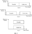
- a location relationship between a time-frequency resource that carries the uplink data and a time-frequency resource that carries the preamble may be any one of case 1 to case 3.
- Case 1 A time domain resource that carries the uplink data and a time domain resource that carries the preamble are consecutive, and a frequency domain resource that carries the uplink data and a frequency domain resource that carries the preamble may be the same or may be different.
- Case 2 The time domain resource that carries the uplink data and the time domain resource that carries the preamble are nonconsecutive, and the frequency domain resource that carries the uplink data and the frequency domain resource that carries the preamble may be the same or may be different.
- Case 3 The time domain resource that carries the uplink data and the time domain resource that carries the preamble are in a same slot (slot), and the frequency domain resource that carries the uplink data and the frequency domain resource that carries the preamble are different.
- the network device receives the preamble from the terminal, and processes the uplink data (denoted as second processing) based on the correspondence between the first uplink configuration and the first random access configuration by using the first uplink configuration corresponding to the first random access configuration.
- step 203 may include: Step (41): The network device receives the preamble from the terminal.
- Step (42) The network device determines the first random access configuration based on the preamble.
- Step (43) The network device determines, based on the correspondence between the first uplink configuration and the first random access configuration, the first uplink configuration corresponding to the first random access configuration.
- Step (44) The network device performs second processing on the uplink data based on the first uplink configuration.
- the network device may determine the first random access configuration based on the preamble and/or a time-frequency resource location used for transmitting the preamble.
- the network device may determine that a random access configuration to which an index of the preamble belongs and/or a random access configuration corresponding to the time-frequency resource location of the preamble are/is the first random access configuration.
- the network device may perform second processing on the uplink data by using information included in the first uplink configuration.
- the second processing is also different.
- the method may further include: Step (51): The network device sends a response message of the uplink data to the terminal, where the response message includes first indication information and/or second indication information, the first indication information is used to indicate whether the response message includes an uplink grant field, and the second indication information is used to indicate whether the response message includes a contention resolution field.
- the first indication information and the second indication information may be located in a reserved bit in the response message or a reserved bit in a MAC header of the response message.
- the response message may include an uplink grant (UL grant), and the terminal may obtain the uplink grant (UL grant) from the response message.
- the response message may include contention resolution information, and the terminal may obtain the contention resolution information from the response message.
- the contention resolution information is used to notify the terminal that random access is completed.
- the contention resolution information may be a part of content of information received from the terminal, for example, may include identifier information of the terminal. Alternatively, contention resolution may be determined through terminal identifier descrambling.
- the network device scrambles cyclic redundancy check (cyclic redundancy check, CRC for short) information of the DCI by using a terminal identifier such as a cell radio network temporary identifier (cell radio network temporary identifier, C-RNTI for short).
- the terminal descrambles the CRC, and then checks the DCI by using the descrambled CRC information. If no transmission error is detected, the DCI is sent to the terminal, and contention resolution succeeds.
- the response message is a MAC CE
- CRC information of DCI indicating a MAC CE resource location may be scrambled.
- the identifier information of the terminal may be sent by the network device to the terminal, and may be allocated by an access network device or may be allocated by a core network device; or may be generated by the terminal, for example, a random value generated by the terminal.
- the response message further includes a timing advance command (timing advance command) and/or a random access preamble identifier (random access preamble index, RAPID for short).
- timing advance command timing advance command
- random access preamble identifier random access preamble index
- the response message may be carried in DCI or a MAC CE.
- the response message may further include a HARQ feedback, and the HARQ feedback is used to indicate whether the uplink data is successfully decoded by the network device.
- a time-frequency resource location of the HARQ feedback in the response message may be mapped to a location by using a time domain resource or a frequency domain resource or a preamble resource associated with a random access configuration, to receive the HARQ feedback in the response message.
- the method further includes: Step (61): The terminal sends uplink control information corresponding to the uplink data to the network device.
- step 203 may include: The network device receives the preamble from the terminal, and the network device performs second processing on the uplink data based on the correspondence between the first uplink configuration and the first random access configuration by using the uplink control information and the first uplink configuration corresponding to the first random access configuration.
- the uplink control information includes any one or more types of the following information: RV indication information, HARQ process indication information, new transmission or retransmission indication information, SCS indication information, precoding indication information, sending repetition count indication information, sending repetition indication information, DMRS mapping type indication information, frequency hopping transmission indication information, piggyback CSI indication information, power offset indication information, waveform indication information, index information of a cell during new transmission, index information of a BWP during new transmission, and HARQ process information during new transmission.
- the uplink configuration may include any one or more types of the following information: MCS table indication information, MCS indication information, time domain resource indication information, frequency domain resource indication information, and TBS indication information.
- one or more types of information used for indicating to send the uplink data are included in the uplink control information corresponding to the uplink data, so that the terminal can more flexibly send the uplink data.
- the network device may perform second processing on the uplink data by using information included in the uplink control information.
- the second processing is also different.
- the uplink configuration may indicate a parameter for sending the uplink data, or may indicate a parameter for sending the uplink control information.
- the time domain resource indication information associated with the uplink configuration may include time domain resource indication information used to transmit the uplink data and/or the uplink control information
- the frequency domain resource indication information may include frequency domain resource indication information used to transmit the uplink data and/or the uplink control information.
- the parameter for sending the uplink data and the parameter for sending the uplink control information may be alternatively included in different uplink configurations. This is not specifically limited in this embodiment of this application. An example in which the uplink data and the uplink control information correspond to a same uplink configuration is used for description in this specification.
- the uplink control information, the uplink data, and the preamble may be included in a same message, for example, all are included in a first message (Msg1), or may be included in different messages.
- a location relationship among a time-frequency resource that carries the uplink data, a time-frequency resource that carries the uplink control information, and a time-frequency resource that carries the preamble may be any one of case 4 to case 6.
- the terminal may send the uplink data in a random access process, to reduce steps of a contention-based random access process and reduce latency of the random access process, thereby improving a capability of adapting to a latency-sensitive scenario.
- the terminal may implement contention-based random access through two steps, to simplify a random access procedure of the terminal and reduce signaling overheads between the terminal and the network device.
- the terminal may select different uplink configurations to process uplink data of different TBSs, so that TB transmission of a plurality of TBSs can be supported.
- First processing corresponding to one piece of information is a processing action when the terminal uses the information
- second processing corresponding to one piece of information is a processing action when the network device uses the information.
- the MCS table indication information is information used to indicate an MCS table, and the MCS table indication information may be an identifier of the MCS table (for example, an index of the MCS table).
- the MCS table includes at least one MCS index, and each MCS index corresponds to one set of parameters.
- the set of parameters may include a modulation rule (modulation order) and a TBS index.
- Table 2 shows an example of an MCS table. In Table 2, each MCS index corresponds to one modulation rule and one TBS index, and one modulation rule and one TBS index correspond to one physical transmission rate. In other words, each MCS index corresponds to a physical transmission rate in one set of parameters.
- the terminal modulates the uplink data and/or the uplink control information by using a modulation rule corresponding to an MCS index in the MCS table indicated by the MCS table indication information, and/or the terminal determines a coding scheme of the uplink data and/or the uplink control information by using a TBS indicated by a TBS index corresponding to an MCS index in the MCS table indicated by the MCS table indication information.
- the network device demodulates the uplink data and/or the uplink control information by using the modulation rule corresponding to the MCS index in the MCS table indicated by the MCS table indication information, and/or the network device determines a decoding scheme of the uplink data and/or the uplink control information by using the TBS indicated by the TBS index corresponding to the MCS index in the MCS table indicated by the MCS table indication information.
- the MCS indication information is information used to indicate an MCS, and the MCS indication information may be an MCS index.
- the terminal modulates the uplink data and/or the uplink control information by using a modulation rule indicated by the MCS indication information, and/or the terminal determines a coding scheme of the uplink data and/or the uplink control information by using a TBS indicated by a TBS index corresponding to the MCS indication information.
- the network device demodulates the uplink data and/or the uplink control information by using the modulation rule indicated by the MCS indication information, and/or the network device determines a decoding scheme of the uplink data and/or the uplink control information by using the TBS indicated by the TBS index corresponding to the MCS indication information.
- the time domain resource indication information is information used to indicate a time domain resource, and the time domain resource indication information may include time domain resource indication information of the uplink data and/or the uplink control information.
- the time domain resource indication information may be slot or symbol information.
- the terminal sends the uplink data and/or the uplink control information on a time domain resource indicated by the time domain resource indication information.
- the network device receives the uplink data and/or the uplink control information on the time domain resource indicated by the time domain resource indication information.
- the frequency domain resource indication information is information used to indicate a frequency domain resource, and the frequency domain resource indication information may include frequency domain resource indication information of the uplink data and/or the uplink control information.
- the frequency domain resource indication information may be a PRB index.
- the terminal sends the uplink data and/or the uplink control information on a frequency domain resource indicated by the frequency domain resource indication information.
- the network device receives the uplink data and/or the uplink control information on the frequency domain resource indicated by the frequency domain resource indication information.
- the TBS indication information is information used to indicate a TBS, and the TBS indication information may be a TBS index.
- the terminal packages the sent uplink data based on a TBS indicated by the TBS indication information.
- the RV indication information is information used to indicate an RV, and the RV indication information may be an RV index.
- the terminal sends the uplink data based on an RV indicated by the RV indication information.
- the network device decodes the uplink data based on the RV indicated by the RV indication information.
- the HARQ process indication information is information used to indicate a HARQ process, and the HARQ process indication information may be a HARQ process index.
- the terminal sends the uplink data by using a HARQ process indicated by the HARQ process indication information.
- the network device receives the uplink data that is sent by the terminal in the HARQ process indicated by the HARQ process indication information.
- the new transmission or retransmission indication information is used to indicate whether the uplink data is newly transmitted data or retransmitted data, and the new transmission or retransmission indication information may be two different values of one bit. For example, a bit value 1 corresponds to the new transmission indication information, and a bit value 0 corresponds to the retransmission indication information.
- the terminal newly transmits or retransmits the uplink data to the network device according to the new transmission or retransmission indication information.
- the network device performs decoding or soft combination on the uplink data according to the new transmission or retransmission indication information.
- the SCS indication information is information used to indicate an SCS, and the SCS indication information may be an SCS index.
- the terminal sends the uplink data by using an SCS indicated by the SCS indication information.
- the network device receives the uplink data by using the SCS indicated by the SCS indication information.
- the precoding indication information is information used to indicate a precoding manner.
- the precoding indication information may be a value of several bits, and different values of these bits represent different precoding manners.
- the terminal performs precoding on the uplink data based on a precoding manner indicated by the precoding indication information.
- the network device decodes the uplink data based on the precoding manner indicated by the precoding indication information.
- the sending repetition count indication information is information used to indicate a sending repetition count.
- the sending repetition count indication information may be a value of several bits, and different values of these bits represent different sending repetition counts.
- the terminal repeatedly sends the uplink data to the network device based on a sending repetition count indicated by the sending repetition count indication information.
- Second processing The network device determines, according to the sending repetition count indication information, which piece of received data is repeated data, and then performs soft combination processing.
- First processing The terminal repeatedly sends the uplink data to the network device according to the sending repetition indication information.
- Second processing The network device determines, according to the sending repetition indication information, that repeated data is to be received.
- the DMRS mapping type indication information is used to indicate a DMRS mapping type, and the DMRS mapping type indication information may be a DMRS mapping type index. Resource elements corresponding to different DMRS mapping types are different. For example, a DMRS location corresponding to a DMRS mapping type 1 is in a symbol 0, and a DMRS location corresponding to a DMRS mapping type 2 is in a symbol 5.
- the terminal maps, by using the DMRS mapping type indicated by the DMRS mapping type indication information, a DMRS corresponding to the uplink data.
- the network device detects a DMRS by using the DMRS mapping type indicated by the DMRS mapping type indication information.
- the frequency hopping transmission indication information is information used to indicate frequency hopping transmission. Whether to perform frequency hopping transmission may be indicated by two different values of one bit. For example, a bit value 1 indicates frequency hopping transmission, and a bit value 0 indicates no frequency hopping transmission.
- the terminal transmits the uplink data through frequency hopping according to the frequency hopping transmission indication information.
- the network device receives the uplink data through frequency hopping according to the frequency hopping transmission indication information.
- the piggyback CSI indication information is information used to indicate to send CSI by multiplexing a time-frequency resource for sending the uplink data. Whether to piggyback the CSI may be indicated by two different values of one bit. For example, a bit value 1 indicates to piggyback the CSI, and a bit value 0 indicates not to piggyback the CSI.
- the terminal sends CSI by multiplexing, according to the piggyback CSI indication information, the time-frequency resource for sending the uplink data.
- the network device obtains, according to the piggyback CSI indication information, CSI on a time-frequency resource for receiving the uplink data.
- the power offset indication information is used to indicate an uplink data and preamble power offset (data-deltapreamble) and/or a power offset associated with the uplink configuration (messagePowerOffset).
- the terminal determines transmit power of the uplink data based on a power offset indicated by the power offset indication information.
- the waveform indication information is used to indicate a waveform used for the uplink data.
- the waveform indicated by the waveform indication information may be any one of the following: cyclic prefix orthogonal frequency division multiplexing (cyclic prefix orthogonal frequency division multiplexing, CP-OFDM for short), discrete fourier transform-spread OFDM (discrete fourier transform-spread OFDM, DFT-S-OFDM for short), and single carrier frequency division multiple access (single-carrier frequency-division multiple access, SC-FDMA for short).
- cyclic prefix orthogonal frequency division multiplexing cyclic prefix orthogonal frequency division multiplexing, CP-OFDM for short
- discrete fourier transform-spread OFDM discrete fourier transform-spread OFDM
- SC-FDMA single carrier frequency division multiple access
- the terminal sends the uplink data based on the waveform indicated by the waveform indication information.
- the network device receives the uplink data based on the waveform indicated by the waveform indication information.
- the index information of the cell is information about a cell to which a time-frequency resource of the uplink data belongs.
- the terminal sends the uplink data in a cell corresponding to an index of the cell by using the time-frequency resource of the uplink data.
- the network device receives the uplink data in the cell corresponding to the index of the cell by using the time-frequency resource of the uplink data.
- the index information of the BWP is information about a BWP to which a time-frequency resource of the uplink data belongs.
- the terminal sends the uplink data in a BWP corresponding to an index of the BWP by using the time-frequency resource of the uplink data.
- the network device receives the uplink data in the BWP corresponding to the index of the BWP by using the time-frequency resource of the uplink data.
- the index information of the cell during new transmission indicates information about a cell to which a time-frequency resource of the uplink data belongs when the uplink data is newly transmitted.
- the network device performs soft combination on the uplink data based on the index information of the cell during new transmission.
- the index information of the BWP during new transmission indicates information about a BWP to which a time-frequency resource of the uplink data belongs when the uplink data is newly transmitted.
- the network device performs soft combination on the uplink data based on the index information of the BWP during new transmission.
- the information about the HARQ process during new transmission indicates information about a HARQ process used for a time-frequency resource of the uplink data when the uplink data is newly transmitted.
- the information about the HARQ process during new transmission may be an index of the HARQ process.
- the network device performs soft combination on the uplink data based on the information about the HARQ process during new transmission.
- the uplink configuration includes time domain resource indication information and frequency domain resource indication information, so that the terminal determines a time-frequency resource for sending the uplink data and/or the uplink control information.
- the time domain resource indication information and the frequency domain resource indication information may be alternatively configured by using another message.
- the uplink configuration does not include the time domain resource indication information or the frequency domain resource indication information.
- the uplink configuration includes MCS indication information. Further, when there are a plurality of MCS tables, the uplink configuration may further include the MCS table indication information. Alternatively, the uplink configuration includes one piece of indication information, and the indication information is used to indicate an MCS table and an MCS. In addition, the uplink configuration may further include time domain resource indication information and frequency domain resource indication information.
- the uplink configuration includes TBS indication information.
- This implementation may also be combined with the foregoing two implementations, that is, content included in the uplink configuration in the foregoing two implementations is included.
- the other information described above may be sent by the terminal to the network device, or may be configured by the network device for the terminal.
- the information may not be transmitted between the terminal and the network device, some information may be preconfigured, some information may be transmitted by using another message, and some information may be transmitted or not transmitted as required.
- any piece of information in the precoding indication information, the sending repetition count indication information, the sending repetition indication information, the DMRS mapping type indication information, the frequency hopping transmission indication information, the piggyback CSI indication information, the index information of the cell, and the index information of the BWP may not be sent by the terminal to the network device, or may not be configured by the network device for the terminal. This may be specifically selected as required.
- the information may be configured in another message instead of sending the information to the terminal by using the foregoing uplink configuration.
- the method includes the following steps.
- a terminal receives at least one random access configuration and at least one uplink configuration from a network device.
- the uplink configuration includes any one or more types of the following information: MCS table indication information, MCS indication information, time domain resource indication information, frequency domain resource indication information, TBS indication information, RV indication information, HARQ process indication information, new transmission or retransmission indication information, SCS indication information, precoding indication information, sending repetition count indication information, sending repetition indication information, DMRS mapping type indication information, frequency hopping transmission indication information, piggyback CSI indication information, power offset indication information, index information of a cell, and index information of a BWP.
- the terminal sends a first message (Msg1) to the network device based on the at least one random access configuration and the at least one uplink configuration and the correspondence between the at least one random access configuration and the at least one uplink configuration, where the first message includes a preamble and uplink data (UL data).
- the network device receives the first message from the terminal.
- step 402 may include: The terminal determines a first uplink configuration corresponding to the uplink data from the at least one uplink configuration, sends the uplink data to the network device based on the first uplink configuration, determines, based on the correspondence between the at least one random access configuration and the at least one uplink configuration, a first random access configuration corresponding to the first uplink configuration, and sends the preamble to the network device based on the first random access configuration.
- the network device receives the preamble from the terminal, and performs second processing on the uplink data based on a correspondence between the first uplink configuration and the first random access configuration by using the first uplink configuration corresponding to the first random access configuration.
- step 403 may include: The network device receives the preamble from the terminal; the network device determines the first random access configuration based on the preamble; the network device determines, based on the correspondence between the first uplink configuration and the first random access configuration, the first uplink configuration corresponding to the first random access configuration; and the network device performs second processing on the uplink data based on the first uplink configuration.
- the network device sends a response message of the first message to the terminal.
- the terminal receives the response message of the first message from the network device.
- the response message of the first message may be used to notify the terminal that the preamble is successfully decoded, or the response message of the first message may be used to notify the terminal that the preamble and the uplink data are successfully decoded.
- step 401 to step 404 if the terminal needs to perform contention-based random access again, only step 402 to step 404 may be performed, and step 401 is not performed.
- the method includes the following steps.
- a terminal receives at least one random access configuration and at least one uplink configuration from a network device.
- the uplink configuration includes any one or more types of the following information: MCS table indication information, MCS indication information, time domain resource indication information, frequency domain resource indication information, and TBS indication information.
- the time domain resource indication information associated with the uplink configuration may include time domain resource indication information used to transmit uplink data and/or uplink control information
- the frequency domain resource indication information may include frequency domain resource indication information used to transmit the uplink data and/or the uplink control information.
- the terminal sends a first message (Msg1) to the network device based on the at least one random access configuration and the at least one uplink configuration and the correspondence between the at least one random access configuration and the at least one uplink configuration, where the first message includes the uplink data, the uplink control information, and a preamble.
- the network device receives the first message from the terminal.
- step 502 may include: The terminal determines a first uplink configuration corresponding to the uplink data from the at least one uplink configuration, sends the uplink data and the uplink control information to the network device based on the first uplink configuration, determines, based on the correspondence between the at least one random access configuration and the at least one uplink configuration, a first random access configuration corresponding to the first uplink configuration, and sends the preamble to the network device based on the first random access configuration.
- the network device receives the preamble from the terminal, and performs second processing on the uplink data based on the uplink control information and a correspondence between the first uplink configuration and the first random access configuration by using the first uplink configuration corresponding to the first random access configuration.
- step 503 may include: The network device receives the preamble from the terminal; the network device determines the first random access configuration based on the preamble; the network device determines, based on the correspondence between the first uplink configuration and the first random access configuration, the first uplink configuration corresponding to the first random access configuration; and the network device performs second processing on the uplink data based on the first uplink configuration and the uplink control information.
- the network device sends a response message of the first message to the terminal.
- the terminal receives the response message of the first message from the network device.
- the response message of the first message may be used to notify the terminal that the preamble is successfully decoded, or the response message of the first message may be used to notify the terminal that the preamble and the uplink data are successfully decoded.
- step 501 to step 504 if the terminal needs to perform contention-based random access again, only step 502 to step 504 may be performed, and step 501 is not performed.
- a contention-based random access process can be implemented only through two steps (one step is to send the first message to the network device and the other step is to receive the response message of the first message from the network device).
- a random access procedure of the terminal is simplified, and signaling overheads and latency between the terminal and the network device are reduced.
- An embodiment of this application further provides a communications apparatus 60 for implementing the foregoing methods.
- the communications apparatus 60 may be the foregoing terminal or network device.
- the communications apparatus 60 may include a processing unit 601 and a communications unit 602, and may further include a storage unit 603.
- the communications unit may also be referred to as a transceiver unit.
- the processing unit 601 is configured to control and manage an action of the terminal.
- the processing unit 601 is configured to support the terminal in performing steps 201 and 202 in FIG. 2 , steps 401, 402, and 404 in FIG. 4 , steps 501, 502, and 504 in FIG. 5 , and/or an action performed by the terminal in another process described in the embodiments of this application.
- the communications unit 602 is configured to support the terminal in communicating with another network device, for example, communicating with the network device in FIG. 4 .
- the storage unit 603 is configured to store program code and data of the terminal.
- the processing unit 601 is configured to control and manage an action of the network device.
- the processing unit 601 is configured to support the network device in performing steps 202 and 203 in FIG. 2 , steps 402 to 404 in FIG. 4 , steps 502 to 504 in FIG. 5 , and/or an action performed by the network device in another process described in the embodiments of this application.
- the communications unit 602 is configured to support the network device in communicating with another network device, for example, communicating with the terminal in FIG. 4 .
- the storage unit 603 is configured to store program code and data of the network device.
- division into the units in the communications apparatus 60 is merely logical function division. During actual implementation, all or some of the units may be integrated into a physical entity, or may be physically separate. In addition, all the units in the communications apparatus 60 may be implemented in a form of software invoked by a processing element, or may be implemented in a form of hardware; or some units may be implemented in a form of software invoked by a processing element, and some units may be implemented in a form of hardware. For example, each unit may be an independently disposed processing element, or may be integrated into a chip of the apparatuses for implementation.
- each unit may be stored in a memory in a form of a program to be invoked by a processing element of the apparatuses to perform a function of the unit.
- all or some of the units may be integrated together, or may be implemented independently.
- the processing element herein may also be referred to as a processor, and may be an integrated circuit having a signal processing capability.
- the steps in the foregoing methods or the foregoing units may be implemented by using a hardware integrated logic circuit of the processor element, or may be implemented in a form of software invoked by the processing element.
- a unit in any one of the foregoing apparatuses may be one or more integrated circuits configured to implement the foregoing methods, for example, one or more specific integrated circuits (application specific integrated circuit, ASIC for short), one or more microprocessors (digital signal processor, DSP for short), one or more field programmable gate arrays (field programmable gate array, FPGA for short), or a combination of at least two of these types of integrated circuits.
- ASIC application specific integrated circuit
- DSP digital signal processor
- FPGA field programmable gate array
- FPGA field programmable gate array
- the processing element may be a general purpose processor, for example, a central processing unit (central processing unit, CPU for short) or another processor that can invoke the program.
- the units may be integrated and implemented in a form of a system-on-a-chip (system-on-a-chip, SOC for short).
- the foregoing unit for receiving is an interface circuit of the communications apparatus 60, and is configured to receive a signal from another apparatus.
- the unit for receiving is an interface circuit that is of the chip and that is configured to receive a signal from another chip or apparatus.
- the foregoing unit for sending is an interface circuit of the communications apparatus 60, and is configured to send a signal to another apparatus.
- the unit for sending is an interface circuit that is of the chip and that is configured to send a signal to another chip or apparatus.
- An embodiment of this application further provides a schematic structural diagram of hardware of a terminal.
- the terminal may be the terminal in the foregoing embodiments, and is configured to implement operations of the terminal in the foregoing embodiments.
- the terminal includes an antenna 701, a radio frequency apparatus 702, and a baseband apparatus 703.
- the antenna 701 is connected to the radio frequency apparatus 702.
- the radio frequency apparatus 702 receives, through the antenna 701, information sent by a network device (for example, receives the at least one uplink configuration and the at least one random access configuration in step 201, step 401, or step 501, or receives the response message of the first message in step 404 or step 504), and sends, to the baseband apparatus 703 for processing, the information sent by the network device.
- the baseband apparatus 703 processes information of the terminal, and sends the information to the radio frequency apparatus 702.
- the radio frequency apparatus 702 sends the information to the network device (for example, sends the uplink data and the preamble in step 202, or sends the first message in step 402 and step 502) through the antenna 701.
- the baseband apparatus 703 may include a modem subsystem, configured to process various communications protocol layers of data.
- the baseband apparatus 703 may further include a central processing subsystem, configured to process an operating system and an application layer of the terminal.
- the baseband apparatus 703 may further include another subsystem, for example, a multimedia subsystem or a peripheral subsystem.
- the multimedia subsystem is configured to control a camera or a screen display of the terminal, and the peripheral subsystem is configured to implement a connection to another device.
- the modem subsystem may be a separately disposed chip.
- the foregoing apparatus used for the terminal may be located in the modem subsystem.
- the modem subsystem may include one or more processing elements 7031, for example, include one main control CPU and another integrated circuit.
- the modem subsystem may further include a storage element 7032 and an interface circuit 7033.
- the processing element 7031 is configured to perform steps of any method performed by the foregoing terminal.
- the storage element 7032 is configured to store data and a program. However, a program used to perform the methods performed by the terminal in the foregoing methods may not be stored in the storage element 7032, but is stored in a memory outside the modem subsystem, and is loaded and used by the modem subsystem when to be used.
- the interface circuit 7033 is configured to communicate with another subsystem.
- the modem subsystem may be implemented by using a chip.
- units of the terminal that implement the steps in the foregoing methods may be implemented by a processing element scheduling a program.
- the apparatus used for the terminal includes a processing element and a storage element.
- the processing element invokes a program stored in the storage element, to perform the methods performed by the terminal in the foregoing method embodiments.
- the storage element may be a storage element located on a same chip as the processing element, namely, an on-chip storage element.
- the program used to perform the methods performed by the terminal in the foregoing methods may be in a storage element located on a different chip from the processing element, namely, an off-chip storage element.
- the processing element invokes or loads the program from the off-chip storage element to the on-chip storage element, to invoke and perform the methods performed by the terminal in the foregoing method embodiments.
- units of the terminal that implement the steps in the foregoing methods may be configured as one or more processing elements. These processing elements are disposed in the modem subsystem.
- the processing element herein may be an integrated circuit, for example, one or more ASICs, one or more DSPs, one or more FPGAs, or a combination of these types of integrated circuits. These integrated circuits may be integrated together to form a chip.
- Units of the terminal that implement the steps in the foregoing methods may be integrated together and implemented in a form of an SOC, and the SOC chip is configured to implement the foregoing methods.
- At least one processing element and storage element may be integrated into the chip, and the processing element invokes a program stored in the storage element to implement the foregoing methods performed by the terminal.
- at least one integrated circuit may be integrated into the chip, to implement the foregoing methods performed by the terminal.
- functions of some units may be implemented by the processing element invoking a program, and functions of some units may be implemented by the integrated circuit.
- the foregoing apparatus used for the terminal may include at least one processing element and interface circuit.
- the at least one processing element is configured to perform any one of the methods that are provided in the foregoing method embodiments and performed by the terminal.
- the processing element may perform some or all steps performed by the terminal, in a first manner, to be specific, by invoking the program stored in the storage element; or may perform some or all steps performed by the terminal, in a second manner, to be specific, by using a hardware integrated logic circuit in the processor element in combination with an instruction; or may certainly perform, by combining the first manner and the second manner, some or all steps performed by the terminal.
- the processing element herein may be a general purpose processor, for example, a CPU, or may be one or more integrated circuits configured to implement the foregoing methods, for example, one or more ASICs, one or more DSPs, one or more FPGAs, or a combination of at least two of the integrated circuits.
- the storage element may be one memory, or may be a general term of a plurality of storage elements.
- the network device may be the network device in the foregoing embodiments, and is configured to implement operations of the network device in the foregoing embodiments.
- the network device includes an antenna 801, a radio frequency apparatus 802, and a baseband apparatus 803.
- the antenna 801 is connected to the radio frequency apparatus 802.
- the radio frequency apparatus 802 receives, through the antenna 801, information sent by a terminal (for example, receives the uplink data and the preamble in step 202, or receives the first message in step 402 and step 502), and sends, to the baseband apparatus 803 for processing, the information sent by the terminal.
- the baseband apparatus 803 processes information of the terminal, and sends the information to the radio frequency apparatus 802.
- the radio frequency apparatus 802 sends the information to the terminal (for example, sends the at least one uplink configuration and the at least one random access configuration in step 201, step 401, or step 501, or sends the response message of the first message in step 404 or step 504) through the antenna 801.
- the baseband apparatus 803 may include one or more processing elements 8031, for example, include one main control CPU and another integrated circuit.
- the baseband apparatus 803 may further include a storage element 8032 and an interface 8033.
- the storage element 8032 is configured to store a program and data.
- the interface 8033 is configured to exchange information with the radio frequency apparatus 802.
- the interface is, for example, a common public radio interface (common public radio interface, CPRI for short).
- the foregoing apparatus used for the network device may be located in the baseband apparatus 803.
- the foregoing apparatus used for the network device may be a chip on the baseband apparatus 803.
- the chip includes at least one processing element and an interface circuit.
- the processing element is configured to perform the steps of any one of the methods performed by the network device.
- the interface circuit is configured to communicate with another apparatus.
- units of the network device that implement the steps in the foregoing methods may be implemented by a processing element scheduling a program.
- the apparatus used for the network device includes a processing element and a storage element.
- the processing element invokes a program stored in the storage element, to perform the methods performed by the network device in the foregoing method embodiments.
- the storage element may be a storage element located on a same chip as the processing element, namely, an on-chip storage element, or may be a storage element located on a different chip from the processing element, namely, an off-chip storage element.
- units of the network device that implement the steps in the foregoing methods may be configured as one or more processing elements. These processing elements are disposed in the baseband apparatus.
- the processing element herein may be an integrated circuit, for example, one or more ASICs, one or more DSPs, one or more FPGAs, or a combination of these types of integrated circuits. These integrated circuits may be integrated together to form a chip.
- Units of the network device that implement the steps in the foregoing methods may be integrated together, and implemented in a form of an SOC.
- the baseband apparatus includes the SOC chip, configured to implement the foregoing methods.
- At least one processing element and storage element may be integrated into the chip, and the processing element invokes a program stored in the storage element to implement the foregoing methods performed by the network device.
- at least one integrated circuit may be integrated into the chip, to implement the foregoing methods performed by the network device.
- functions of some units may be implemented by the processing element invoking a program, and functions of some units may be implemented by the integrated circuit.
- the foregoing apparatus used for the network device may include at least one processing element and interface circuit.
- the at least one processing element is configured to perform any one of the methods that are provided in the foregoing method embodiments and performed by the network device.
- the processing element may perform some or all steps performed by the network device, in a first manner, to be specific, by invoking the program stored in the storage element; or may perform some or all steps performed by the network device, in a second manner, to be specific, by using a hardware integrated logic circuit in the processor element in combination with an instruction; or may certainly perform, by combining the first manner and the second manner, some or all steps performed by the network device.
- the processing element herein may be a general purpose processor, for example, a CPU, or may be one or more integrated circuits configured to implement the foregoing methods, for example, one or more ASICs, one or more DSPs, one or more FPGAs, or a combination of at least two of the integrated circuits.
- the storage element may be one memory, or may be a general term of a plurality of storage elements.
- An embodiment of this application further provides a communications system.
- the communications system includes the foregoing terminal and the foregoing network device.
- An embodiment of this application further provides a computer storage medium.
- the computer storage medium includes a computer instruction.
- the processor is enabled to perform any method provided in the foregoing embodiments.
- An embodiment of this application further provides a computer program product including an instruction.
- the instruction When the instruction is run on a processor, the processor is enabled to perform any method provided in the foregoing embodiments.
- All or some of the foregoing embodiments may be implemented by using software, hardware, firmware, or any combination thereof.
- the embodiments may be implemented completely or partially in a form of a computer program product.
- the computer program product includes one or more computer program instructions.
- the computer program instructions When the computer program instructions are loaded and executed on a computer, the procedure or functions according to the embodiments of this application are all or partially generated.
- the computer may be a general-purpose computer, a dedicated computer, a computer network, or another programmable apparatus.
- the computer instructions may be stored in a computer-readable storage medium or may be transmitted from a computer-readable storage medium to another computer-readable storage medium.
- the computer instructions may be transmitted from a website, computer, server, or data center to another website, computer, server, or data center in a wired (for example, a coaxial cable, an optical fiber, or a digital subscriber line (digital subscriber line, DSL for short)) or wireless (for example, infrared, radio, or microwave) manner.
- the computer-readable storage medium may be any usable medium accessible by the computer, or a data storage device, such as a server or a data center, integrating one or more usable media.
- the usable medium may be a magnetic medium (for example, a floppy disk, a hard disk, or a magnetic tape), an optical medium (for example, a DVD), a semiconductor medium (for example, a solid-state drive (solid state disk, SSD for short)), or the like.
- a magnetic medium for example, a floppy disk, a hard disk, or a magnetic tape
- an optical medium for example, a DVD
- a semiconductor medium for example, a solid-state drive (solid state disk, SSD for short)
Applications Claiming Priority (2)
| Application Number | Priority Date | Filing Date | Title |
|---|---|---|---|
| CN201811057307.XA CN110891315B (zh) | 2018-09-11 | 2018-09-11 | 通信方法、装置及计算机存储介质 |
| PCT/CN2019/105236 WO2020052573A1 (fr) | 2018-09-11 | 2019-09-10 | Procédé et appareil de communication, et support de stockage informatique |
Publications (2)
| Publication Number | Publication Date |
|---|---|
| EP3836695A1 true EP3836695A1 (fr) | 2021-06-16 |
| EP3836695A4 EP3836695A4 (fr) | 2021-11-10 |
Family
ID=69745564
Family Applications (1)
| Application Number | Title | Priority Date | Filing Date |
|---|---|---|---|
| EP19859592.8A Pending EP3836695A4 (fr) | 2018-09-11 | 2019-09-10 | Procédé et appareil de communication, et support de stockage informatique |
Country Status (6)
| Country | Link |
|---|---|
| US (1) | US11778619B2 (fr) |
| EP (1) | EP3836695A4 (fr) |
| CN (1) | CN110891315B (fr) |
| AU (1) | AU2019338023A1 (fr) |
| CA (1) | CA3112419A1 (fr) |
| WO (1) | WO2020052573A1 (fr) |
Families Citing this family (5)
| Publication number | Priority date | Publication date | Assignee | Title |
|---|---|---|---|---|
| CN110972317B (zh) * | 2018-09-28 | 2022-06-28 | 华为技术有限公司 | 通信方法和装置 |
| US11950291B2 (en) * | 2018-09-28 | 2024-04-02 | Sony Group Corporation | System and method for random access channel (RACH) procedure configuration |
| CN114070515A (zh) * | 2020-08-06 | 2022-02-18 | 上海朗帛通信技术有限公司 | 一种被用于无线通信的节点中的方法和装置 |
| WO2022067716A1 (fr) * | 2020-09-30 | 2022-04-07 | 北京小米移动软件有限公司 | Procédé et dispositif de communication et support de stockage lisible par ordinateur |
| WO2024065806A1 (fr) * | 2022-09-30 | 2024-04-04 | Oppo广东移动通信有限公司 | Procédé de communication sans fil, dispositif terminal et dispositif de réseau |
Family Cites Families (9)
| Publication number | Priority date | Publication date | Assignee | Title |
|---|---|---|---|---|
| CN104981022B (zh) * | 2014-04-04 | 2020-07-10 | 北京三星通信技术研究有限公司 | 数据传输的方法、基站及终端 |
| CN105490790B (zh) * | 2014-10-13 | 2019-03-05 | 成都鼎桥通信技术有限公司 | 载波聚合中辅载波的配置方法和装置 |
| US10660133B2 (en) * | 2015-12-03 | 2020-05-19 | Seoul National University R&Db Foundation | Method and system for random access and uplink data transmission for low latency communication |
| CN106993332B (zh) * | 2016-01-20 | 2019-07-02 | 中兴通讯股份有限公司 | 上行调度的方法及装置 |
| US10651996B2 (en) * | 2016-09-29 | 2020-05-12 | Qualcomm Incorporated | Techniques for dynamic demodulation reference signal patterns for data transmission |
| CN108282874B (zh) * | 2017-01-06 | 2019-08-16 | 电信科学技术研究院 | 一种数据传输方法、装置及系统 |
| CN108289329B (zh) * | 2017-01-09 | 2023-08-29 | 北京三星通信技术研究有限公司 | 随机接入的方法及基站设备、用户设备 |
| BR112019014484A2 (pt) * | 2017-01-13 | 2020-02-11 | Motorola Mobility Llc | Método e aparelho para realizar acesso aleatório com base em contenção em uma frequência de portadora |
| EP3726914A1 (fr) * | 2017-08-10 | 2020-10-21 | Comcast Cable Communications, LLC | Activation de transmission sans subvention |
-
2018
- 2018-09-11 CN CN201811057307.XA patent/CN110891315B/zh active Active
-
2019
- 2019-09-10 AU AU2019338023A patent/AU2019338023A1/en not_active Abandoned
- 2019-09-10 CA CA3112419A patent/CA3112419A1/fr not_active Abandoned
- 2019-09-10 WO PCT/CN2019/105236 patent/WO2020052573A1/fr unknown
- 2019-09-10 EP EP19859592.8A patent/EP3836695A4/fr active Pending
-
2021
- 2021-03-10 US US17/197,533 patent/US11778619B2/en active Active
Also Published As
| Publication number | Publication date |
|---|---|
| CN110891315B (zh) | 2022-09-09 |
| US11778619B2 (en) | 2023-10-03 |
| CA3112419A1 (fr) | 2020-03-19 |
| CN110891315A (zh) | 2020-03-17 |
| EP3836695A4 (fr) | 2021-11-10 |
| AU2019338023A9 (en) | 2021-11-25 |
| WO2020052573A1 (fr) | 2020-03-19 |
| US20210195584A1 (en) | 2021-06-24 |
| AU2019338023A1 (en) | 2021-04-15 |
Similar Documents
| Publication | Publication Date | Title |
|---|---|---|
| CN109417525B (zh) | 用于发送和接收下行链路信号的方法和设备 | |
| US11778619B2 (en) | Communication method and apparatus, and computer storage medium | |
| CA3072524A1 (fr) | Procede de transmission en liaison montante, dispositif terminal et dispositif reseau | |
| US10674499B2 (en) | Carrier indication method, user equipment, and base station | |
| EP4188016A1 (fr) | Appareil terminal, appareil de station de base et procédé de communication | |
| EP3768013A1 (fr) | Dispositif terminal, dispositif de station de base et procédé de communication | |
| EP4192164A1 (fr) | Procédé de détermination de ressources de domaine fréquentiel, dispositif, et support de stockage | |
| EP3902366A1 (fr) | Procédé et appareil de communication | |
| WO2020145271A1 (fr) | Équipement utilisateur et stations de base réalisant des répétitions basées sur des mini-créneaux | |
| JP7156887B2 (ja) | 端末装置、基地局装置、および、通信方法 | |
| TW201924455A (zh) | 用於nr中prach和pusch分離的不同方法 | |
| WO2021024922A1 (fr) | Multiplexage de harq-ack de différents types de service sur un seul pusch | |
| US20230101648A1 (en) | Information transmission method, terminal device, and network device | |
| US20210160859A1 (en) | Communications method and apparatus | |
| CN114026939A (zh) | 用于下行链路控制信息(dci)格式的dci的用户设备、基站和方法 | |
| WO2023206107A1 (fr) | Procédé de planification de dispositif terminal et appareil associé | |
| WO2021090604A1 (fr) | Équipements utilisateurs, stations de base et procédés pour informations de commande de liaison descendante configurables pour signal de référence de démodulation pour canal physique partagé de liaison montante | |
| US20230085338A1 (en) | User equipments, base stations, and methods | |
| WO2021090616A1 (fr) | Équipements utilisateur, stations de base et procédés servant à des informations de commande de liaison descendante configurables concernant un signal de référence de démodulation d'un canal physique partagé de liaison descendante | |
| WO2021060231A1 (fr) | Équipements utilisateur, stations de base et procédés de transmission(s) d'un canal de commande de liaison montante physique (pucch) et d'un canal partagé de liaison montante physique (pusch) | |
| WO2020143713A9 (fr) | Procédé et dispositif de communication et support d'informations | |
| WO2020098662A1 (fr) | Procédé et appareil de communication permettant d'envoyer et de recevoir un canal physique de commande de liaison descendante | |
| CN111699741B (zh) | 终端装置、基站装置以及通信方法 | |
| US20230189234A1 (en) | Frequency Domain Resource Determining Method, Device, and Storage Medium | |
| WO2022071229A1 (fr) | Dispositif terminal, dispositif de station de base et procédé de communication |
Legal Events
| Date | Code | Title | Description |
|---|---|---|---|
| STAA | Information on the status of an ep patent application or granted ep patent |
Free format text: STATUS: THE INTERNATIONAL PUBLICATION HAS BEEN MADE |
|
| PUAI | Public reference made under article 153(3) epc to a published international application that has entered the european phase |
Free format text: ORIGINAL CODE: 0009012 |
|
| STAA | Information on the status of an ep patent application or granted ep patent |
Free format text: STATUS: REQUEST FOR EXAMINATION WAS MADE |
|
| 17P | Request for examination filed |
Effective date: 20210312 |
|
| AK | Designated contracting states |
Kind code of ref document: A1 Designated state(s): AL AT BE BG CH CY CZ DE DK EE ES FI FR GB GR HR HU IE IS IT LI LT LU LV MC MK MT NL NO PL PT RO RS SE SI SK SM TR |
|
| A4 | Supplementary search report drawn up and despatched |
Effective date: 20211011 |
|
| RIC1 | Information provided on ipc code assigned before grant |
Ipc: H04W 72/04 20090101AFI20211005BHEP |
|
| DAV | Request for validation of the european patent (deleted) | ||
| DAX | Request for extension of the european patent (deleted) | ||
| STAA | Information on the status of an ep patent application or granted ep patent |
Free format text: STATUS: EXAMINATION IS IN PROGRESS |
|
| 17Q | First examination report despatched |
Effective date: 20230628 |