EP3836616A1 - Data sending method and apparatus, storage medium, and sending end - Google Patents
Data sending method and apparatus, storage medium, and sending end Download PDFInfo
- Publication number
- EP3836616A1 EP3836616A1 EP19846311.9A EP19846311A EP3836616A1 EP 3836616 A1 EP3836616 A1 EP 3836616A1 EP 19846311 A EP19846311 A EP 19846311A EP 3836616 A1 EP3836616 A1 EP 3836616A1
- Authority
- EP
- European Patent Office
- Prior art keywords
- sending end
- end logical
- logical channels
- sending
- pdcp
- Prior art date
- Legal status (The legal status is an assumption and is not a legal conclusion. Google has not performed a legal analysis and makes no representation as to the accuracy of the status listed.)
- Granted
Links
Images



Classifications
-
- H—ELECTRICITY
- H04—ELECTRIC COMMUNICATION TECHNIQUE
- H04W—WIRELESS COMMUNICATION NETWORKS
- H04W80/00—Wireless network protocols or protocol adaptations to wireless operation
- H04W80/02—Data link layer protocols
-
- H—ELECTRICITY
- H04—ELECTRIC COMMUNICATION TECHNIQUE
- H04W—WIRELESS COMMUNICATION NETWORKS
- H04W72/00—Local resource management
- H04W72/12—Wireless traffic scheduling
-
- H—ELECTRICITY
- H04—ELECTRIC COMMUNICATION TECHNIQUE
- H04W—WIRELESS COMMUNICATION NETWORKS
- H04W28/00—Network traffic management; Network resource management
- H04W28/02—Traffic management, e.g. flow control or congestion control
- H04W28/10—Flow control between communication endpoints
- H04W28/12—Flow control between communication endpoints using signalling between network elements
-
- H—ELECTRICITY
- H04—ELECTRIC COMMUNICATION TECHNIQUE
- H04W—WIRELESS COMMUNICATION NETWORKS
- H04W72/00—Local resource management
- H04W72/04—Wireless resource allocation
-
- H—ELECTRICITY
- H04—ELECTRIC COMMUNICATION TECHNIQUE
- H04W—WIRELESS COMMUNICATION NETWORKS
- H04W76/00—Connection management
- H04W76/10—Connection setup
- H04W76/15—Setup of multiple wireless link connections
Definitions
- the present disclosure generally relates to communication technology field, and more particularly, to a data sending method and apparatus, a storage medium and a sending end.
- 3GPP has introduced New Radio (NR) access technology to meet the demand of larger data volume and smaller transmission delay.
- NR New Radio
- This technology is also known as the fifth-generation mobile communication technology (5G).
- Packet Data Convergence Protocol (PDCP) duplication function and Band Width Part (BWP).
- PDCP Packet Data Convergence Protocol
- BWP Band Width Part
- the PDCP replication function is introduced to improve the reliability of Ultra Reliable Low Latency Communication (URLLC) service transmission. More specifically, a PDCP data packet is duplicated into two same duplicates at a PDCP layer of a sending end, where the two same duplicates are sent to two different Radio Link Control (RLC) entities respectively, and then sent through different sending end Logical Channels (LCH). When the two duplicates are successfully received, a PDCP layer at a receiving end keeps one of them and deletes the other one. In other words, a data packet is duplicated into two same duplicates and transmitted through two different channels, thereby improving the reliability of data transmission. And the PDCP data packet may include a PDCP Protocol Data Unit (PDU) and a PDCP Service Data Unit (SDU).
- PDU PDCP Protocol Data Unit
- SDU PDCP Service Data Unit
- a radio bearer (RB) configured with duplication function may be configured with more than two wireless data legs.
- RB it is not clear to use only one bit to indicate how many sending end logical channels to be used are used to send duplicated PDCP data packets, and which sending end logical channels to be used are used for data transmission.
- one bit only includes two states of 0/1, that is, it can only be used to indicate two logical channels, and cannot clearly indicate the use of multi-connectivity duplication.
- Embodiments of the present disclosure provide a data sending method and apparatus, a storage medium and a sending end, which can improve accuracy of instructions, thereby improving efficiency of transmission resource utilization.
- a data sending method including: determining an activation instruction which includes multiple bits to indicate sending end logical channels to be used for each Radio Bearer (RB); and for each RB, according to a number n of the sending end logical channels to be used for the RB, a sending end Packet Data Convergence Protocol (PDCP) entity duplicating a PDCP data packet and sending duplicated PDCP data packets to a receiving end through the sending end logical channels to be used; wherein a maximum value of the number n of the sending end logical channels to be used for each RB is greater than 2.
- PDCP Packet Data Convergence Protocol
- each of the multiple bits indicates whether a corresponding sending end logical channel is a sending end logical channel to be used; wherein each bit of the multiple bits has a one-to-one mapping relationship with each sending end logical channel.
- the one-to-one mapping relationship between each bit of the multiple bits and each sending end logical channel is predefined.
- the data sending method further includes: determining a PDCP duplication configuration information, wherein the PDCP duplication configuration information includes a mapping relationship between each sending end PDCP entity and a sending end logical channel, and the one-to-one mapping relationship between each bit of the multiple bits and each sending end logical channel; wherein each RB corresponds to a sending end PDCP entity.
- the PDCP duplication configuration information further includes a mapping relationship between the sending end logical channels and sub-bands.
- RBs indicated by the multiple bits in the activation instruction are arranged in an order of sequence numbers of the RBs, and the bits indicating a same RB are arranged in an order of sequence numbers of the sending end logical channels; and wherein the order of sequence numbers of the RBs and the order of sequence numbers of the sending end logical channels are ascending or descending, and the order of sequence numbers of the RBs and the order of sequence numbers of the sending end logical channels are same or different.
- CA Carrier Aggregation
- RBs indicated by the multiple bits in the activation instruction are arranged in an order of sequence numbers of the RBs, and the bits indicating a same RB are arranged in an order of sequence numbers of sending end Media Access Control (MAC) layers; and wherein the order of sequence numbers of the RBs and the order of sequence numbers of the sending end MAC layers are ascending or descending, and the order of sequence numbers of the RBs and the order of sequence numbers of the sending end MAC layers are same or different.
- DC Dual Connectivity
- a value of the multiple bits indicating a RB indicates the number n of the sending end logical channels to be used for each RB, where the sending end logical channels of each RB are arranged in a preset order; and according to the preset order, top n sending end logical channels are selected as the sending end logical channels to be used for each RB.
- the data sending method further includes: determining a PDCP duplication configuration information, wherein the PDCP duplication configuration information includes a mapping relationship between each PDCP entity and each sending end logical channel, and the preset order of the sending end logical channels of each RB.
- the PDCP duplication configuration information further includes a mapping relationship between the sending end logical channels and sub-bands.
- the multiple bits used to indicate the sending end logical channels to be used for each RB are a preset number of bits
- the data sending method further includes: determining a PDCP duplication configuration information, wherein the PDCP duplication configuration information includes a mapping relationship between each PDCP entity and each sending end logical channel, the preset order of the sending end logical channels of each RB, and the preset number of bits.
- the data sending method further includes: determining a PDCP duplication configuration information, wherein the PDCP duplication configuration information includes a mapping relationship between each PDCP entity and each sending end logical channel, the preset order of the sending end logical channels of each RB, and a preset value of a maximum number of the sending end logical channels of each RB.
- the PDCP duplication configuration information further includes a mapping relationship between the sending end logical channels and sub-bands.
- a data sending apparatus including: an activation determination module, adapted to determine an activation instruction which includes multiple bits to indicate sending end logical channels to be used for each Radio Bearer (RB); and a sending module, adapted to, for each RB, send duplicated Packet Data Convergence Protocol (PDCP) data packets to a receiving end through the sending end logical channels to be used, wherein the duplicated PDCP data packets are generated by a sending end PDCP entity duplicating a PDCP data packet according to a number n of the sending end logical channels to be used for the RB; wherein a maximum value of the number n of the sending end logical channels to be used for each RB is greater than 2.
- PDCP Packet Data Convergence Protocol
- each of the multiple bits indicates whether a corresponding sending end logical channel is a sending end logical channel to be used; wherein each bit of the multiple bits has a one-to-one mapping relationship with each sending end logical channel.
- the one-to-one mapping relationship between each bit of the multiple bits and each sending end logical channel is predefined.
- the data sending apparatus further includes: a first configuration information determining module, adapted to, before determining the activation instruction, determine a PDCP duplication configuration information, wherein the PDCP duplication configuration information includes a mapping relationship between each sending end PDCP entity and a sending end logical channel, and the one-to-one mapping relationship between each bit of the multiple bits and each sending end logical channel; wherein each RB corresponds to a sending end PDCP entity.
- a first configuration information determining module adapted to, before determining the activation instruction, determine a PDCP duplication configuration information, wherein the PDCP duplication configuration information includes a mapping relationship between each sending end PDCP entity and a sending end logical channel, and the one-to-one mapping relationship between each bit of the multiple bits and each sending end logical channel; wherein each RB corresponds to a sending end PDCP entity.
- the PDCP duplication configuration information further includes a mapping relationship between the sending end logical channels and sub-bands.
- RBs indicated by the multiple bits in the activation instruction are arranged in an order of sequence numbers of the RBs, and the bits indicating a same RB are arranged in an order of sequence numbers of the sending end logical channels; and wherein the order of sequence numbers of the RBs and the order of sequence numbers of the sending end logical channels are ascending or descending, and the order of sequence numbers of the RBs and the order of sequence numbers of the sending end logical channels are same or different.
- CA Carrier Aggregation
- RBs indicated by the multiple bits in the activation instruction are arranged in an order of sequence numbers of the RBs, and the bits indicating a same RB are arranged in an order of sequence numbers of sending end Media Access Control (MAC) layers; and wherein the order of sequence numbers of the RBs and the order of sequence numbers of the sending end MAC layers are ascending or descending, and the order of sequence numbers of the RBs and the order of sequence numbers of the sending end MAC layers are same or different.
- DC Dual Connectivity
- a value of the multiple bits indicating a RB indicates the number n of the sending end logical channels to be used for each RB, where the sending end logical channels of each RB are arranged in a preset order; and according to the preset order, top n sending end logical channels are selected as the sending end logical channels to be used for each RB.
- the data sending apparatus further includes: a second configuration information determining module, adapted to, before determining the activation instruction, determine a PDCP duplication configuration information, wherein the PDCP duplication configuration information includes a mapping relationship between each PDCP entity and each sending end logical channel, and the preset order of the sending end logical channels of each RB.
- a second configuration information determining module adapted to, before determining the activation instruction, determine a PDCP duplication configuration information, wherein the PDCP duplication configuration information includes a mapping relationship between each PDCP entity and each sending end logical channel, and the preset order of the sending end logical channels of each RB.
- the PDCP duplication configuration information further includes a mapping relationship between the sending end logical channels and sub-bands.
- the multiple bits used to indicate the sending end logical channels to be used for each RB are a preset number of bits
- the data sending apparatus further includes: a third configuration information determining module, adapted to determine a PDCP duplication configuration information before determining the activation instruction, wherein the PDCP duplication configuration information includes a mapping relationship between each PDCP entity and each sending end logical channel, the preset order of the sending end logical channels of each RB, and the preset number of bits.
- the data sending apparatus further includes: a fourth configuration information determining module, adapted to determine a PDCP duplication configuration information, wherein the PDCP duplication configuration information includes a mapping relationship between each PDCP entity and each sending end logical channel, the preset order of the sending end logical channels of each RB, and a preset value of a maximum number of the sending end logical channels of each RB.
- a fourth configuration information determining module adapted to determine a PDCP duplication configuration information, wherein the PDCP duplication configuration information includes a mapping relationship between each PDCP entity and each sending end logical channel, the preset order of the sending end logical channels of each RB, and a preset value of a maximum number of the sending end logical channels of each RB.
- the PDCP duplication configuration information further includes a mapping relationship between the sending end logical channels and sub-bands.
- a storage medium having computer instructions stored therein is provided, wherein once the computer instructions are executed, the above data sending method is performed.
- a sending end including a memory and a processor
- the memory has computer instructions stored therein, and when the processor executes the computer instructions, the above data sending method is performed.
- Embodiments of the present disclosure may provide following advantages.
- multiple bits are used to indicate sending end logical channels to be used for each RB by setting an activation instruction.
- only one bit is used to indicate sending end logical channels to be used for each RB, which is not clear in the case of multiple-connectivity duplication.
- n of sending end logical channels of each RB is greater than 2
- multiple bits are used to indicate, which facilitates to improve the accuracy of indication and improve the efficiency of transmission resource utilization.
- the activation instruction uses each of the multiple bits of the activation instruction to indicate whether a corresponding sending end logical channel is a sending end logical channel to be used, so that the sending end can determine whether a sender logical channel corresponding to each bit of the multiple bits is a sending logical channel to be used, so that the sending end logical channel to be used is determined when data needs to be sent.
- a value of the multiple bits indicating a RB indicates the number n of the sending end logical channels to be used for each RB, where the sending end logical channels of each RB are arranged in a preset order; and according to the preset order, top n sending end logical channels are selected as the sending end logical channels to be used for each RB.
- the sending end may use fewer bits to indicate the sending end logical channels to be used, so that the sending end can determine the sending end logical channels to be used of each RB according to the value of the multiple bits indicating the RB and the preset order, and determine the sending end logical channels when data needs to be sent.
- the multiple bits used to indicate the sending end logical channels to be used for each RB are a preset number of bits
- the PDCP duplication configuration information includes a mapping relationship between each PDCP entity and each sending end logical channel, the preset order of the sending end logical channels of each RB and the preset number of bits.
- a preset number of bits may be used to represent each RB in a received instruction, and the sending end may separate the multiple bits corresponding to each RB without calculation, which facilitates to reduce computational complexity.
- activation/deactivation mechanism of two-leg duplication mode is supported. Specifically, for each Radio Bearer (RB) configured with duplication function, a bit is used to indicate activation or deactivation of the duplication function of the RB.
- the activation of the duplication function can be used to instruct a PDCP to perform duplication operation and both two legs can be used for data transmission; the deactivation of the duplication function can be used to instruct the PDCP not to perform duplication operation and only a primary leg can be used for data transmission.
- an RB configured with duplication function may be configured with more than two wireless data legs.
- For each RB it is not clear to use only one bit to indicate how many sending end logical channels to be used are used to send duplicated PDCP data packets, and which sending end logical channels to be used are used for data transmission.
- one bit only includes two states of 0/1, that is, it can only be used to indicate two logical channels, and cannot clearly indicate the use of multi-connectivity duplication.
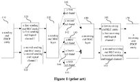
- FIG. 1 schematically illustrate a working scenario diagram of a data sending method in prior art.
- the data sending method may be used in a PDCP duplication function architecture in a Carrier Aggregation (CA) scenario.
- CA Carrier Aggregation
- a sending end PDCP entity 110 sends PDCP data packets to a first sending end RLC entity 121 and a second sending end RLC entity 122 respectively, and the PDCP data packets are sent to a sending end Medium Access Control (MAC) layer 130 through a first sending end logical channel corresponding to the first sending end RLC entity 121 and a second sending end logical channel corresponding to the second sending end RLC entity 122 respectively.
- MAC Medium Access Control
- the PDCP data packets will be sent through different sub-bands respectively. For example, a PDCP data packet sent by the first sending end logical channel will be sent through a first sub-band 141 and a second sub-band 142, and a PDCP data packet sent by the second sending end logical channel will be sent through a third sub-band 143, a fourth sub-band 144 and a fifth sub-band 145.
- a receiving end MAC layer 150 receives the PDCP data packets through different sub-bands, such as the first sub-band 141, the second sub-band 142, the third sub-band 143, the fourth sub-band 144 and the fifth sub-band 145, respectively. And the PDCP data packets will be uploaded to a first receiving end RLC entity 161 and a second receiving end RLC entity 162 correspondingly, and then be uploaded to a receiving end PDCP entity 170 the through a first receiving end logical channel corresponding to the first receiving end RLC entity 161 and a second receiving end logical channel corresponding to the second receiving end RLC entity 162.
- each leg may be a path from the sending end PDCP entity 110 to the receiving end PDCP entity 170, for example, from a sending end PDCP entity, a sending end RLC entity, a sending end MAC layer, a sub-band, a receiving end MSC layer, a receiving end RLC entity, to a receiving end PDCP entity.
- a plurality of steps such as configuration, activation and deactivation may be performed to realize the duplication function.
- a network side may use a Radio Resource Control (RRC) message to configure PDCP duplication function for multiple RBs, and establish an additional duplication RLC entity for each RB; wherein the RRC message may also indicate a sub-band Cell group ID and a Logic Channel ID (LCID) of a main RLC entity.
- RRC Radio Resource Control
- the RRC message may also set a duplication initial state for the RBs (for example, activation/deactivation).
- the two RLC entities are also configured to be mapped to different carriers respectively.
- the activation step is needed to perform the duplication function.
- the activation/deactivation step is performed by sending an activation/deactivation MAC control element (CE) from the network side.
- the MAC CE includes a bitmap, where each bit of the bitmap corresponds to a RB configured with duplication. Specifically, if a certain bit corresponding to a certain RB is configured with 1, it indicates to activate the certain RB; and if a certain bit corresponding to a certain RB is configured with 0, it indicates to deactivate the certain RB.
- the RB may include a Data Radio Bearer (DRB) and a Signaling Radio Bearer (SRB).
- DRB Data Radio Bearer
- SRB Signaling Radio Bearer
- the PDCP layer duplicates the data packet and sends the two same duplicated PDCP Protocol Data Units (PDUs) to two RLC entities corresponding to the RB respectively, and the two RLC entities will send the two same duplicated PDCP PDUs respectively.
- PDUs PDCP Protocol Data Units
- the sending end PDCP layer will not duplicate new data packets.
- the new data packets will be sent to a primary RLC entity (ie, a primary LCH), and not to a secondary RLC entity (ie, a secondary LCH).
- the sending end PDCP entity will notify the secondary RLC entity to cancel data stored in the secondary LCH.
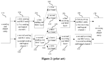
- Figure 2 schematically illustrate another working scenario diagram of a data sending method in prior art.
- the data sending method can be used in a PDCP duplication function architecture in a Dual Connectivity (DC) scenario.
- DC Dual Connectivity
- multiple sending end MAC layers and multiple receiving end MAC layers are provided.
- the multiple sending end MAC layers include a first sending end MAC layer 231 and a second sending end MAC layer 232;
- the multiple receiving end MAC layers include a first receiving end MAC layer 251 and a second receiving end MAC layer 252.
- each leg is a path from a sending end PDCP entity 110 to a receiving end PDCP entity 170, for example, from a sending end PDCP entity, a sending end RLC entity, a sending end MAC layer, a sub-band, a receiving end MAC layer, a receiving end RLC entity to a receiving end PDCP entity.
- the multiple sending end MAC layers correspond to the multiple sending end RLC entities
- the multiple receiving end MAC layers correspond to the multiple receiving end RLC entities.
- a plurality of steps such as configuration, activation and deactivation may be performed to realize the duplication function.
- the configuration step may be similar to that in the CA scenario.
- the activation step is needed to perform the duplication function.
- the activation/deactivation step is performed by sending an activation/deactivation MAC CE from the network side.
- the MAC CE includes a bitmap, where each bit of the bitmap corresponds to a RB configured with duplication. Specifically, if a certain bit corresponding to a certain RB is configured with 1, it indicates to activate the certain RB; and if a certain bit corresponding to a certain RB is configured with 0, it indicates to deactivate the certain RB.
- the PDCP layer duplicates the data packet and sends the two same duplicated PDCP Protocol Data Units (PDUs) to two RLC entities corresponding to the RB respectively, and the two RLC entities will send the two same duplicated PDCP PDUs respectively.
- PDUs PDCP Protocol Data Units
- the UE falls back to a split operation and adopts a relevant configuration of the split operation.
- a RB configured with duplication function may be configured with more than two legs for multiple-connectivity duplication, that is, more than two sending end logical channels may be configured.
- a bit it is not clear to use only one bit to indicate how many sending end logical channels to be used are used to send duplicated PDCP data packets, and which sending end logical channels to be used are used for data transmission.
- one bit only includes two states of 0/1, that is, it can only be used to indicate two logical channels, and cannot clearly indicate the use of multi-connectivity duplication.
- multiple bits are used to indicate sending end logical channels to be used for each RB by setting an activation instruction.
- only one bit is used to indicate sending end logical channels to be used for each RB, which is not clear in the case of multiple-connectivity duplication.
- n of sending end logical channels of each RB is greater than 2
- multiple bits are used to indicate, which facilitates to improve the accuracy of indication and improve the efficiency of transmission resource utilization.
- Figure 3 schematically illustrates a flow chart of a data sending method according to an embodiment.
- the data sending method includes S31 to S32.
- an activation instruction which includes multiple bits to indicate sending end logical channels to be used for each RB is determined.
- a sending end Packet Data Convergence Protocol (PDCP) entity duplicates a PDCP data packet to generate duplicated PDCP data packets, wherein the duplicated PDCP data packets are sent to a receiving end through the sending end logical channels to be used; and wherein a maximum value of the number n of the sending end logical channels to be used for each RB is greater than 2.
- PDCP Packet Data Convergence Protocol
- the operation of determining the activation instruction may be performed in different ways, depending on whether the sending end is a base station or a user equipment.
- the operation of determining activation instruction may include: configuring and sending the activation instruction to a user equipment, so that the user equipment determines the sending end logical channels to be used for each RB according to the multiple bits in the activation instruction.
- the operation of determining the activation instruction may include: receiving the activation instruction from a base station.
- the activation instruction may be transmitted through a MAC CE signaling. It should be noted that in embodiments of the present disclosure, methods of transmitting the activation instruction is not limited.
- each of the multiple bits indicates whether a corresponding sending end logical channel is a sending end logical channel to be used; wherein each bit of the multiple bits has a one-to-one mapping relationship with each sending end logical channel.
- a bit set to be 1 may be used to indicate that a corresponding sending end logical channel is a sending end logical channel to be used, and a bit set to be 0 may be used to indicate that a corresponding sending end logical channel is not a sending end logical channel to be used.
- the one-to-one mapping relationship between each bit of the multiple bits and each sending end logical channel is predefined.
- the RBs corresponding to the multiple bits and the sending end logical channels may be arranged in an ascending order, which may be predefined through a protocol and cannot be modified.
- the one-to-one mapping relationship between each bit of the multiple bits and each sending end logical channel may be sent from a network side (for example, a base station) to a user equipment, for example, a PDCP duplication configuration information may be configured.
- a network side for example, a base station
- a user equipment for example, a PDCP duplication configuration information
- the data sending method further includes: determining the PDCP duplication configuration information.
- the PDCP duplication configuration information includes a mapping relationship between each sending end PDCP entity and a sending end logical channel, and the one-to-one mapping relationship between each bit of the multiple bits and each sending end logical channel; wherein each RB corresponds to a sending end PDCP entity.
- the PDCP duplication configuration information includes a mapping relationship between each sending end PDCP entity and a sending end logical channel, and the one-to-one mapping relationship between each bit of the multiple bits and each sending end logical channel.
- the PDCP duplication configuration information may further includes a mapping relationship between the sending end logical channels and sub-bands.
- the PDCP duplication configuration information may include the one-to-one mapping relationship between each bit of the multiple bits and each sending end logical channel in detail. In other embodiments, the PDCP duplication configuration information may only include a sequence of the multiple bits in the activation instruction, so that, after receiving the activation instruction, the user equipment may determine the one-to-one mapping relationship between each bit of the multiple bits and each sending end logical channel.
- Figure 4 schematically illustrates a working scenario diagram of a data sending method according to an embodiment.
- the data sending method shown in Figure 4 may be used in a CA duplication, where a RB that is configured with a PDCP duplication includes n legs, that is, n sending end logical channels.
- a sending end PDCP entity 410 may send PDCP data packets to a first sending end RLC entity 421, a second sending end RLC entity 422, ... a n-th sending end RLC entity 423, and then the send PDCP data packets may be sent to a sending end MAC layer 430 through a first sending end logical channel corresponding to the first sending end RLC entity 421, a second sending end logical channel corresponding to the second sending end RLC entity 422, ... a nth sending end logical channel corresponding to the nth sending end RLC entity 423; where n is a positive integer.
- the PDCP data packets may be sent through different sub-bands, for example, a first sub-band 441, a second sub-band 442, ..., a nth sub-band 443.
- numbers of specific sub-bands included in the first sub-band 441, the second sub-band 442, and the nth sub-band 443 are not limited, that is, the first sub-band 441, the second sub-band 442, and the nth sub-band 443 may include a sub-band group respectively.
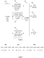
- Figure 5 is a schematic diagram of multiple bits in an activation instruction of a data sending method according to an embodiment.
- RBs indicated by multiple bits in the activation instruction are arranged in an order of sequence numbers of the RBs, and the bits indicating a same RB are arranged in an order of sequence numbers of sending end logical channels; and wherein the order of sequence numbers of the RBs and the order of sequence numbers of the sending end logical channels are ascending or descending, and the order of sequence numbers of the RBs and the order of sequence numbers of the sending end logical channels are same or different.
- multiple bits in the activation instruction are configured in two hierarchies: firstly, the RBs may be arranged in an ascending or descending order of sequence numbers of the RBs; secondly, logical channels (LCHs) may be arranged in an ascending or descending order of sequence numbers of the LCHs; and then a value of each bit in the multiple bits may be configured in the order of arrangement. As shown in Figure 5 , the multiple bits in the activation instruction are configured in the ascending order of sequence numbers of the RBS and the sending end logical channels.
- LCHs logical channels
- the order of sequence numbers of the RBs and the order of sequence numbers of the sending end logical channels are same or different. That is, the sequence numbers of the RBs may be arranged in the ascending order, but the sequence numbers of the sending end logical channels may be arranged in the descending order; or, the sequence numbers of the RBs may be arranged in the descending order, but the sequence numbers of the sending end logical channels may be arranged in the ascending order.
- Figure 6 is a schematic diagram of multiple bits in an activation instruction of a data sending method according to another embodiment.
- the data sending method shown in Figure 6 may be used in a DC duplication, where RBs configured with PDCP duplication function has n legs.
- a sending end PDCP entity 610 may send PDCP data packets to a first sending end RLC entity 621, a second sending end RLC entity 622, ... a nth sending end RLC entity 623, and the PDCP data packets are sent to a first sending end MAC layer 631 through a first sending end logical channel corresponding to the first sending end RLC entity 621, a seocnd sending end MAC layer 632 through a first sending end logical channel corresponding to the seocnd sending end RLC entity 622, and a nth sending end MAC layer 633 through a nth sending end logical channel corresponding to the nth sending end RLC entity 623, where n is a positive integer.
- the PDCP data packets may be sent through different sub-bands respectively.
- a PDCP data packet sent by the first sending end logical channel may be sent through a first sub-band 641
- a PDCP data packet sent by the second sending end logical channel may be sent through a second sub-band 642
- a PDCP data packet sent by the nth sending end logical channel may be sent through a nth sub-band 643.
- numbers of specific sub-bands included in the first sub-band 641, the second sub-band 642, and the nth sub-band 643 are not limited, that is, the first sub-band 641, the second sub-band 642, and the nth sub-band 643 may include a sub-band group respectively.
- Figure 7 is a schematic diagram of multiple bits in an activation instruction of a data sending method according to another embodiment.
- RBs indicated by multiple bits in an activation instruction are arranged in an order of sequence numbers of the RBs, and bits indicating a same RB are arranged in an order of sequence numbers of sending end MAC layers, wherein the order of sequence numbers of the RBs and the order of sequence numbers of the sending end MAC layers are ascending or descending, and the order of sequence numbers of the RBs and the order of sequence numbers of the sending end MAC layers are same or different.
- the multiple bits in the activation instruction are configured in two hierarchies: firstly, the RBs may be arranged in an ascending or descending order of sequence numbers of the RBs; secondly, the sending end logical channels may be arranged in an ascending or descending order of sequence numbers of the sending end logical channels; and then a value of each bit in the multiple bits may be configured in the order of arrangement. As shown in Figure 5 , the multiple bits in the activation instruction are configured in the ascending order of sequence numbers of the RBS and the sending end logical channels.
- the order of sequence numbers of the RBs and the order of sequence numbers of the sending end logical channels are same or different. That is, the sequence numbers of the RBs may be arranged in the ascending order, but the sequence numbers of the sending end logical channels may be arranged in the descending order; or, the sequence numbers of the RBs may be arranged in the descending order, but the sequence numbers of the sending end logical channels may be arranged in the ascending order.
- the activation instruction uses each of the multiple bits of the activation instruction to indicate whether a corresponding sending end logical channel is a sending end logical channel to be used, so that the sending end can determine whether a sender logical channel corresponding to each bit of the multiple bits is a sending logical channel to be used, so that the sending end logical channel to be used is determined when data needs to be sent.
- a value of the multiple bits indicating a RB indicates the number n of the sending end logical channels to be used for each RB, where the sending end logical channels of each RB are arranged in a preset order; and according to the preset order, top n sending end logical channels are selected as the sending end logical channels to be used for each RB.
- the multiple bits in the activation instruction are used to indicate the number n of the sending end logical channel to be used for each RB in the multiple RBs respectively, that is, the value of the multiple bits indicating a RB indicates the number n of the sending end logical channels to be used for each RB, and the UE is defaulted to use the first n sending end logical channels.
- the preset order may be used to indicate priorities of the sending end logical channels in each RB. For example, a sending end logical channel with a higher priority may be set to have a smaller sequence number, so that the sending end logical channel with a higher priority is more likely to be selected.
- the method before determining the activation instruction, the method further includes: determining a PDCP duplication configuration information.
- the PDCP duplication configuration information includes a mapping relationship between each PDCP entity and each sending end logical channel, and the preset order of the sending end logical channels of each RB.
- the PDCP duplication configuration information includes a mapping relationship between each PDCP entity and each sending end logical channel, and the preset order of the sending end logical channels of each RB, and a mapping relationship between the sending end logical channels and sub-bands.
- Figure 8 is a schematic diagram of multiple bits indicating a same RB in an activation instruction of a data sending method according to an embodiment.
- RB1 is "10"
- a value of the multiple bits is 2 and a number n of sending end logical channels to be used for RB1 indicated by the multiple bits is 2, that is, first two sending end logical channels are used;
- multiple bits indicating a RB i.e. RB1
- a value of the multiple bits is 3 and a number n of sending end logical channels to be used for RB 1 indicated by the multiple bits is 3, that is, first 3 sending end logical channels are used.
- the multiple bits in the activation instruction are configured in two hierarchies: firstly, the RBs may be arranged in an ascending or descending order of sequence numbers of the RBs; secondly, for each RB, a value of one or multiple bits may be use to indicate the number n.
- bi represents a number of bits in the activation instruction indicating sending end logical channels to be used for an i-th RB; and n i represents a number of sending end logical channels of the i-th RB.
- the multiple bits used to indicate the sending end logical channels to be used for different RBs may be same or different. If the number of the sending end logical channels to be used changes, the multiple bits used to indicate the sending end logical channels to be used may also change accordingly. Specifically, the user equipment may calculate to determine the multiple bits used to indicate the sending end logical channels to be used for each RB according to the above formula, and then determine the sending end logical channels to be used for each RB.
- the activation instruction uses the value of the multiple bits indicating each RB to indicate the number n of the sending end logical channels to be used, wherein the sending end logical channels of each RB are arranged in a preset order; according to the preset order, top n sending end logical channels are selected as the sending end logical channels to be used.
- the sending end may use fewer bits to indicate the sending end logical channels to be used, so that the sending end can determine the sending end logical channels to be used of each RB according to the value of the multiple bits indicating the RB and the preset order, and determine the sending end logical channels when data needs to be sent.
- the multiple bits used to indicate the sending end logical channels to be used for each RB are a preset number of bits
- the data sending method further includes: determining a PDCP duplication configuration information, wherein the PDCP duplication configuration information includes a mapping relationship between each PDCP entity and each sending end logical channel, the preset order of the sending end logical channels of each RB and the preset number of bits.
- the PDCP duplication configuration information further includes a mapping relationship between the sending end logical channels and sub-bands.
- a preset number of bits may be used to represent each RB in a received instruction, and the sending end may separate the multiple bits corresponding to each RB without calculation, which facilitates to reduce computational complexity.
- the data sending method before determining the activation instruction, further includes: determining a PDCP duplication configuration information, wherein the PDCP duplication configuration information includes a mapping relationship between each PDCP entity and each sending end logical channel, the preset order of the sending end logical channels of each RB, and a preset value of a maximum number of the sending end logical channels of each RB.
- the PDCP duplication configuration information further includes a mapping relationship between the sending end logical channels and sub-bands.
- b i represents a number of bits in the activation instruction indicating sending end logical channels to be used for an i-th RB; and N represents the maximum number of the sending end logical channels of each RB.
- the number of bits calculated according to the above formula can completely indicate all legs which are configured with the replication function.
- the number of bits may be set to be b i calculated according to the above formula, even if the number of legs changes, b i does not need to be changed.
- the activation instruction may use the preset number of bits to indicate each RB, and the sender does not need to calculate for each RB separately.
- multiple bits corresponding to each RB may be separated according to b i , which facilitates to reduce computational complexity.
- the sending end PDCP entity duplicates the PDCP data packet to generate duplicated PDCP data packets and sends the duplicated PDCP data packets to a receiving end through the sending end logical channels to be used, where a maximum value of the number n of the sending end logical channels of each RB is greater than 2.
- the PDCP entity receives a data packet from an upper layer and duplicates it at the PDCP entity's layer. Specifically, if the number of the sending end logical channels to be used is N, the PDCP entity duplicates the PDCP data packet (N-1) times to obtain N PDCP data packets in total, and then sends the original PDCP data packet and the duplicated (N-1) PDCP data packets to the receiver through the sending end logical channels.
- multiple bits are used to indicate sending end logical channels to be used for each RB by setting an activation instruction.
- only one bit is used to indicate sending end logical channels to be used for each RB, which is not clear in the case of multiple-connectivity duplication.
- n of sending end logical channels of each RB is greater than 2
- multiple bits are used to indicate, which facilitates to improve the accuracy of indication and improve the efficiency of transmission resource utilization.
- Figure 9 is a structural diagram of a data sending apparatus according to an embodiment.
- the data sending apparatus includes:
- each of the multiple bits indicates whether a corresponding sending end logical channel is a sending end logical channel to be used; wherein each bit of the multiple bits has a one-to-one mapping relationship with each sending end logical channel.
- the one-to-one mapping relationship between each bit of the multiple bits and each sending end logical channel is predefined.
- the PDCP duplication configuration information further includes a mapping relationship between the sending end logical channels and sub-bands.
- RBs indicated by the multiple bits in the activation instruction are arranged in an order of sequence numbers of the RBs, and the bits indicating a same RB are arranged in an order of sequence numbers of sending end MAC layers; and wherein the order of sequence numbers of the RBs and the order of sequence numbers of the sending end MAC layers are ascending or descending, and the order of sequence numbers of the RBs and the order of sequence numbers of the sending end MAC layers are same or different.
- RBs indicated by the multiple bits in the activation instruction are arranged in an order of sequence numbers of the RBs, and the bits indicating a same RB are arranged in an order of sequence numbers of the sending end logical channels; and wherein the order of sequence numbers of the RBs and the order of sequence numbers of the sending end logical channels are ascending or descending, and the order of sequence numbers of the RBs and the order of sequence numbers of the sending end logical channels are same or different.
- a value of the multiple bits indicating a RB indicates the number n of the sending end logical channels to be used for each RB, where the sending end logical channels of each RB are arranged in a preset order; and according to the preset order, top n sending end logical channels are selected as the sending end logical channels to be used for each RB.
- the PDCP duplication configuration information further includes a mapping relationship between the sending end logical channels and sub-bands.
- the multiple bits used to indicate the sending end logical channels to be used for each RB are a preset number of bits
- the data sending apparatus further includes: a third configuration information determining module, adapted to determine a PDCP duplication configuration information before determining the activation instruction, wherein the PDCP duplication configuration information includes a mapping relationship between each PDCP entity and each sending end logical channel, the preset order of the sending end logical channels of each RB, and the preset number of bits.
- the PDCP duplication configuration information further includes a mapping relationship between the sending end logical channels and sub-bands.
- a storage medium having computer instructions stored therein is provided, wherein once the computer instructions are executed, the above data sending method illustrated in Figure 3 is performed.
- the storage medium may be a computer readable storage medium, for example, including a non-volatile or non-transitory memory, an optical disk, a mechanical disk, a solid disk or the like.
- a sending end including a memory and a processor
- the memory has computer instructions stored therein, and when the processor executes the computer instructions, the above method as shown in Figure 3 is performed.
- the sending end may include but not limited to a network equipment such as a base stations or a server, and a terminal equipment such as a mobile phone, a computers or a tablet.
Landscapes
- Engineering & Computer Science (AREA)
- Computer Networks & Wireless Communication (AREA)
- Signal Processing (AREA)
- Mobile Radio Communication Systems (AREA)
Abstract
Description
- This application claims the benefit of priority to Chinese Patent Application No.
201810908301.2, filed on August 10, 2018 - The present disclosure generally relates to communication technology field, and more particularly, to a data sending method and apparatus, a storage medium and a sending end.
- With the development of wireless communication technology, 3GPP has introduced New Radio (NR) access technology to meet the demand of larger data volume and smaller transmission delay. This technology is also known as the fifth-generation mobile communication technology (5G).
- In 5G, two new technologies are introduced: Packet Data Convergence Protocol (PDCP) duplication function and Band Width Part (BWP).
- Specifically, the PDCP replication function is introduced to improve the reliability of Ultra Reliable Low Latency Communication (URLLC) service transmission. More specifically, a PDCP data packet is duplicated into two same duplicates at a PDCP layer of a sending end, where the two same duplicates are sent to two different Radio Link Control (RLC) entities respectively, and then sent through different sending end Logical Channels (LCH). When the two duplicates are successfully received, a PDCP layer at a receiving end keeps one of them and deletes the other one. In other words, a data packet is duplicated into two same duplicates and transmitted through two different channels, thereby improving the reliability of data transmission. And the PDCP data packet may include a PDCP Protocol Data Unit (PDU) and a PDCP Service Data Unit (SDU).
- However, for multi-connectivity duplication, a radio bearer (RB) configured with duplication function may be configured with more than two wireless data legs. For each RB, it is not clear to use only one bit to indicate how many sending end logical channels to be used are used to send duplicated PDCP data packets, and which sending end logical channels to be used are used for data transmission. Specifically, one bit only includes two states of 0/1, that is, it can only be used to indicate two logical channels, and cannot clearly indicate the use of multi-connectivity duplication.
- Embodiments of the present disclosure provide a data sending method and apparatus, a storage medium and a sending end, which can improve accuracy of instructions, thereby improving efficiency of transmission resource utilization.
- In an embodiment of the present disclosure, a data sending method is provided, including: determining an activation instruction which includes multiple bits to indicate sending end logical channels to be used for each Radio Bearer (RB); and for each RB, according to a number n of the sending end logical channels to be used for the RB, a sending end Packet Data Convergence Protocol (PDCP) entity duplicating a PDCP data packet and sending duplicated PDCP data packets to a receiving end through the sending end logical channels to be used; wherein a maximum value of the number n of the sending end logical channels to be used for each RB is greater than 2.
- Optionally, each of the multiple bits indicates whether a corresponding sending end logical channel is a sending end logical channel to be used; wherein each bit of the multiple bits has a one-to-one mapping relationship with each sending end logical channel.
- Optionally, the one-to-one mapping relationship between each bit of the multiple bits and each sending end logical channel is predefined.
- Optionally, before determining the activation instruction, the data sending method further includes: determining a PDCP duplication configuration information, wherein the PDCP duplication configuration information includes a mapping relationship between each sending end PDCP entity and a sending end logical channel, and the one-to-one mapping relationship between each bit of the multiple bits and each sending end logical channel; wherein each RB corresponds to a sending end PDCP entity.
- Optionally, the PDCP duplication configuration information further includes a mapping relationship between the sending end logical channels and sub-bands.
- Optionally, in a Carrier Aggregation (CA) duplication, RBs indicated by the multiple bits in the activation instruction are arranged in an order of sequence numbers of the RBs, and the bits indicating a same RB are arranged in an order of sequence numbers of the sending end logical channels; and wherein the order of sequence numbers of the RBs and the order of sequence numbers of the sending end logical channels are ascending or descending, and the order of sequence numbers of the RBs and the order of sequence numbers of the sending end logical channels are same or different.
- Optionally, in a Dual Connectivity (DC) duplication, RBs indicated by the multiple bits in the activation instruction are arranged in an order of sequence numbers of the RBs, and the bits indicating a same RB are arranged in an order of sequence numbers of sending end Media Access Control (MAC) layers; and wherein the order of sequence numbers of the RBs and the order of sequence numbers of the sending end MAC layers are ascending or descending, and the order of sequence numbers of the RBs and the order of sequence numbers of the sending end MAC layers are same or different.
- Optionally, a value of the multiple bits indicating a RB indicates the number n of the sending end logical channels to be used for each RB, where the sending end logical channels of each RB are arranged in a preset order; and according to the preset order, top n sending end logical channels are selected as the sending end logical channels to be used for each RB.
- Optionally, before determining the activation instruction, the data sending method further includes: determining a PDCP duplication configuration information, wherein the PDCP duplication configuration information includes a mapping relationship between each PDCP entity and each sending end logical channel, and the preset order of the sending end logical channels of each RB.
- Optionally, the PDCP duplication configuration information further includes a mapping relationship between the sending end logical channels and sub-bands.
- Optionally, a number of bits used to indicate the sending end logical channels to be used for each RB is determined according to a following formula: bi = ┌log2(ni +1)┐; wherein bi represents a number of bits in the activation instruction indicating sending end logical channels to be used for an i-th RB; and ni represents a number of sending end logical channels of the i-th RB.
- Optionally, the multiple bits used to indicate the sending end logical channels to be used for each RB are a preset number of bits, and before determining the activation instruction, the data sending method further includes: determining a PDCP duplication configuration information, wherein the PDCP duplication configuration information includes a mapping relationship between each PDCP entity and each sending end logical channel, the preset order of the sending end logical channels of each RB, and the preset number of bits.
- Optionally, before determining the activation instruction, the data sending method further includes: determining a PDCP duplication configuration information, wherein the PDCP duplication configuration information includes a mapping relationship between each PDCP entity and each sending end logical channel, the preset order of the sending end logical channels of each RB, and a preset value of a maximum number of the sending end logical channels of each RB.
- Optionally, a number of bits used to indicate the sending end logical channels to be used for each RB is determined according to a following formula: bi = ┌log2(N+1)┐; wherein bi represents a number of bits in the activation instruction indicating sending end logical channels to be used for an i-th RB; and N represents the maximum number of the sending end logical channels of each RB.
- Optionally, the PDCP duplication configuration information further includes a mapping relationship between the sending end logical channels and sub-bands.
- In an embodiment of the present disclosure, a data sending apparatus is provided, including: an activation determination module, adapted to determine an activation instruction which includes multiple bits to indicate sending end logical channels to be used for each Radio Bearer (RB); and a sending module, adapted to, for each RB, send duplicated Packet Data Convergence Protocol (PDCP) data packets to a receiving end through the sending end logical channels to be used, wherein the duplicated PDCP data packets are generated by a sending end PDCP entity duplicating a PDCP data packet according to a number n of the sending end logical channels to be used for the RB; wherein a maximum value of the number n of the sending end logical channels to be used for each RB is greater than 2.
- Optionally, each of the multiple bits indicates whether a corresponding sending end logical channel is a sending end logical channel to be used; wherein each bit of the multiple bits has a one-to-one mapping relationship with each sending end logical channel.
- Optionally, the one-to-one mapping relationship between each bit of the multiple bits and each sending end logical channel is predefined.
- Optionally, the data sending apparatus further includes: a first configuration information determining module, adapted to, before determining the activation instruction, determine a PDCP duplication configuration information, wherein the PDCP duplication configuration information includes a mapping relationship between each sending end PDCP entity and a sending end logical channel, and the one-to-one mapping relationship between each bit of the multiple bits and each sending end logical channel; wherein each RB corresponds to a sending end PDCP entity.
- Optionally, the PDCP duplication configuration information further includes a mapping relationship between the sending end logical channels and sub-bands.
- Optionally, in a Carrier Aggregation (CA) duplication, RBs indicated by the multiple bits in the activation instruction are arranged in an order of sequence numbers of the RBs, and the bits indicating a same RB are arranged in an order of sequence numbers of the sending end logical channels; and wherein the order of sequence numbers of the RBs and the order of sequence numbers of the sending end logical channels are ascending or descending, and the order of sequence numbers of the RBs and the order of sequence numbers of the sending end logical channels are same or different.
- Optionally, in a Dual Connectivity (DC) duplication, RBs indicated by the multiple bits in the activation instruction are arranged in an order of sequence numbers of the RBs, and the bits indicating a same RB are arranged in an order of sequence numbers of sending end Media Access Control (MAC) layers; and wherein the order of sequence numbers of the RBs and the order of sequence numbers of the sending end MAC layers are ascending or descending, and the order of sequence numbers of the RBs and the order of sequence numbers of the sending end MAC layers are same or different.
- Optionally, a value of the multiple bits indicating a RB indicates the number n of the sending end logical channels to be used for each RB, where the sending end logical channels of each RB are arranged in a preset order; and according to the preset order, top n sending end logical channels are selected as the sending end logical channels to be used for each RB.
- Optionally, the data sending apparatus further includes: a second configuration information determining module, adapted to, before determining the activation instruction, determine a PDCP duplication configuration information, wherein the PDCP duplication configuration information includes a mapping relationship between each PDCP entity and each sending end logical channel, and the preset order of the sending end logical channels of each RB.
- Optionally, the PDCP duplication configuration information further includes a mapping relationship between the sending end logical channels and sub-bands.
- Optionally, a number of bits used to indicate the sending end logical channels to be used for each RB is determined according to a following formula: bi = ┌log2(ni+1)┐; wherein bi represents a number of bits in the activation instruction indicating sending end logical channels to be used for an i-th RB; and ni represents a number of sending end logical channels of the i-th RB.
- Optionally, the multiple bits used to indicate the sending end logical channels to be used for each RB are a preset number of bits, and the data sending apparatus further includes: a third configuration information determining module, adapted to determine a PDCP duplication configuration information before determining the activation instruction, wherein the PDCP duplication configuration information includes a mapping relationship between each PDCP entity and each sending end logical channel, the preset order of the sending end logical channels of each RB, and the preset number of bits.
- Optionally, the data sending apparatus further includes: a fourth configuration information determining module, adapted to determine a PDCP duplication configuration information, wherein the PDCP duplication configuration information includes a mapping relationship between each PDCP entity and each sending end logical channel, the preset order of the sending end logical channels of each RB, and a preset value of a maximum number of the sending end logical channels of each RB.
- Optionally, a number of bits used to indicate the sending end logical channels to be used for each RB is determined according to a following formula: bi =┌log2(N+1)┐; wherein bi represents a number of bits in the activation instruction indicating sending end logical channels to be used for an i-th RB; and N represents the maximum number of the sending end logical channels of each RB.
- Optionally, the PDCP duplication configuration information further includes a mapping relationship between the sending end logical channels and sub-bands.
- In an embodiment of the present disclosure, a storage medium having computer instructions stored therein is provided, wherein once the computer instructions are executed, the above data sending method is performed.
- In an embodiment of the present disclosure, a sending end including a memory and a processor is provided, wherein the memory has computer instructions stored therein, and when the processor executes the computer instructions, the above data sending method is performed.
- Embodiments of the present disclosure may provide following advantages.
- In embodiments of the present disclosure, multiple bits are used to indicate sending end logical channels to be used for each RB by setting an activation instruction. However in prior art, only one bit is used to indicate sending end logical channels to be used for each RB, which is not clear in the case of multiple-connectivity duplication. According to the embodiments of the present disclosure, when a maximum number n of sending end logical channels of each RB is greater than 2, multiple bits are used to indicate, which facilitates to improve the accuracy of indication and improve the efficiency of transmission resource utilization.
- Further, the activation instruction uses each of the multiple bits of the activation instruction to indicate whether a corresponding sending end logical channel is a sending end logical channel to be used, so that the sending end can determine whether a sender logical channel corresponding to each bit of the multiple bits is a sending logical channel to be used, so that the sending end logical channel to be used is determined when data needs to be sent.
- Further, a value of the multiple bits indicating a RB indicates the number n of the sending end logical channels to be used for each RB, where the sending end logical channels of each RB are arranged in a preset order; and according to the preset order, top n sending end logical channels are selected as the sending end logical channels to be used for each RB. In the embodiment of the present disclosure, the sending end may use fewer bits to indicate the sending end logical channels to be used, so that the sending end can determine the sending end logical channels to be used of each RB according to the value of the multiple bits indicating the RB and the preset order, and determine the sending end logical channels when data needs to be sent.
- Further, the multiple bits used to indicate the sending end logical channels to be used for each RB are a preset number of bits, and the PDCP duplication configuration information includes a mapping relationship between each PDCP entity and each sending end logical channel, the preset order of the sending end logical channels of each RB and the preset number of bits. According to the embodiments of the present disclosure, a preset number of bits may be used to represent each RB in a received instruction, and the sending end may separate the multiple bits corresponding to each RB without calculation, which facilitates to reduce computational complexity.
-
-
Figure 1 schematically illustrates a working scenario diagram of a data sending method in prior art; -
Figure 2 schematically illustrates another working scenario diagram of a data sending method in prior art; -
Figure 3 schematically illustrates a flow chart of a data sending method according to an embodiment; -
Figure 4 schematically illustrates a working scenario diagram of a data sending method according to an embodiment; -
Figure 5 is a schematic diagram of multiple bits in an activation instruction of a data sending method according to an embodiment; -
Figure 6 schematically illustrates a working scenario diagram of a data sending method according to another embodiment; -
Figure 7 is a schematic diagram of multiple bits in an activation instruction of a data sending method according to another embodiment; -
Figure 8 is a schematic diagram of multiple bits indicating a same RB in an activation instruction of a data sending method according to an embodiment; and -
Figure 9 is a structural diagram of a data sending apparatus according to an embodiment. - In prior art, activation/deactivation mechanism of two-leg duplication mode is supported. Specifically, for each Radio Bearer (RB) configured with duplication function, a bit is used to indicate activation or deactivation of the duplication function of the RB. The activation of the duplication function can be used to instruct a PDCP to perform duplication operation and both two legs can be used for data transmission; the deactivation of the duplication function can be used to instruct the PDCP not to perform duplication operation and only a primary leg can be used for data transmission.
- However, for multi-connectivity duplication, an RB configured with duplication function may be configured with more than two wireless data legs. For each RB, it is not clear to use only one bit to indicate how many sending end logical channels to be used are used to send duplicated PDCP data packets, and which sending end logical channels to be used are used for data transmission. Specifically, one bit only includes two states of 0/1, that is, it can only be used to indicate two logical channels, and cannot clearly indicate the use of multi-connectivity duplication.
- Referring to
Figure 1, Figure 1 schematically illustrate a working scenario diagram of a data sending method in prior art. The data sending method may be used in a PDCP duplication function architecture in a Carrier Aggregation (CA) scenario. - In the data sending method, a sending
end PDCP entity 110 sends PDCP data packets to a first sendingend RLC entity 121 and a second sendingend RLC entity 122 respectively, and the PDCP data packets are sent to a sending end Medium Access Control (MAC)layer 130 through a first sending end logical channel corresponding to the first sendingend RLC entity 121 and a second sending end logical channel corresponding to the second sendingend RLC entity 122 respectively. - Since the first sending end logical channel and the second sending end logical channel are respectively mapped to different sub-bands, the PDCP data packets will be sent through different sub-bands respectively. For example, a PDCP data packet sent by the first sending end logical channel will be sent through a
first sub-band 141 and asecond sub-band 142, and a PDCP data packet sent by the second sending end logical channel will be sent through athird sub-band 143, afourth sub-band 144 and afifth sub-band 145. - Further, a receiving
end MAC layer 150 receives the PDCP data packets through different sub-bands, such as thefirst sub-band 141, thesecond sub-band 142, thethird sub-band 143, thefourth sub-band 144 and thefifth sub-band 145, respectively. And the PDCP data packets will be uploaded to a first receivingend RLC entity 161 and a second receivingend RLC entity 162 correspondingly, and then be uploaded to a receivingend PDCP entity 170 the through a first receiving end logical channel corresponding to the first receivingend RLC entity 161 and a second receiving end logical channel corresponding to the second receivingend RLC entity 162. - Specifically, each leg may be a path from the sending
end PDCP entity 110 to the receivingend PDCP entity 170, for example, from a sending end PDCP entity, a sending end RLC entity, a sending end MAC layer, a sub-band, a receiving end MSC layer, a receiving end RLC entity, to a receiving end PDCP entity. - In the existing PDCP duplication function architecture in the CA scenario, a plurality of steps, such as configuration, activation and deactivation may be performed to realize the duplication function.
- Specifically, in the configuration step, a network side (for example, a base station) may use a Radio Resource Control (RRC) message to configure PDCP duplication function for multiple RBs, and establish an additional duplication RLC entity for each RB; wherein the RRC message may also indicate a sub-band Cell group ID and a Logic Channel ID (LCID) of a main RLC entity. The RRC message may also set a duplication initial state for the RBs (for example, activation/deactivation).
- In the CA scenario, usually only one MAC entity is needed. Through the RRC message, the two RLC entities are also configured to be mapped to different carriers respectively.
- Furthermore, after the configuration step is completed, the activation step is needed to perform the duplication function. The activation/deactivation step is performed by sending an activation/deactivation MAC control element (CE) from the network side. The MAC CE includes a bitmap, where each bit of the bitmap corresponds to a RB configured with duplication. Specifically, if a certain bit corresponding to a certain RB is configured with 1, it indicates to activate the certain RB; and if a certain bit corresponding to a certain RB is configured with 0, it indicates to deactivate the certain RB.
- The RB may include a Data Radio Bearer (DRB) and a Signaling Radio Bearer (SRB).
- In the activation step, after a certain RB configured with duplication is activated, the PDCP layer duplicates the data packet and sends the two same duplicated PDCP Protocol Data Units (PDUs) to two RLC entities corresponding to the RB respectively, and the two RLC entities will send the two same duplicated PDCP PDUs respectively.
- In the deactivation step, after a certain RB configured with duplication is deactivated, a corresponding restriction between a corresponding logical channel (LCH) and a carrier is cancelled; the sending end PDCP layer will not duplicate new data packets. The new data packets will be sent to a primary RLC entity (ie, a primary LCH), and not to a secondary RLC entity (ie, a secondary LCH). In addition, the sending end PDCP entity will notify the secondary RLC entity to cancel data stored in the secondary LCH.
- Referring to
Figure 2, Figure 2 schematically illustrate another working scenario diagram of a data sending method in prior art. The data sending method can be used in a PDCP duplication function architecture in a Dual Connectivity (DC) scenario. - Referring to
Figure 2 , multiple sending end MAC layers and multiple receiving end MAC layers are provided. For example, the multiple sending end MAC layers include a first sendingend MAC layer 231 and a second sendingend MAC layer 232; the multiple receiving end MAC layers include a first receivingend MAC layer 251 and a second receivingend MAC layer 252. - In some embodiments, each leg is a path from a sending
end PDCP entity 110 to a receivingend PDCP entity 170, for example, from a sending end PDCP entity, a sending end RLC entity, a sending end MAC layer, a sub-band, a receiving end MAC layer, a receiving end RLC entity to a receiving end PDCP entity. Specifically, the multiple sending end MAC layers correspond to the multiple sending end RLC entities, and the multiple receiving end MAC layers correspond to the multiple receiving end RLC entities. - In the existing PDCP duplication function architecture in the DC scenario, a plurality of steps, such as configuration, activation and deactivation may be performed to realize the duplication function.
- In some embodiments, the configuration step may be similar to that in the CA scenario.
- Furthermore, after the configuration step is completed, the activation step is needed to perform the duplication function. The activation/deactivation step is performed by sending an activation/deactivation MAC CE from the network side. The MAC CE includes a bitmap, where each bit of the bitmap corresponds to a RB configured with duplication. Specifically, if a certain bit corresponding to a certain RB is configured with 1, it indicates to activate the certain RB; and if a certain bit corresponding to a certain RB is configured with 0, it indicates to deactivate the certain RB.
- In the activation step, after a certain RB configured with duplication is activated, the PDCP layer duplicates the data packet and sends the two same duplicated PDCP Protocol Data Units (PDUs) to two RLC entities corresponding to the RB respectively, and the two RLC entities will send the two same duplicated PDCP PDUs respectively.
- In the deactivation step, after a certain RB configured with duplication is deactivated, the UE falls back to a split operation and adopts a relevant configuration of the split operation.
- However, in the prior art, in the case of multiple-connectivity duplication, indication accuracy needs to be improved.
- Inventors of the present disclosure discovered that, in the prior art, a RB configured with duplication function may be configured with more than two legs for multiple-connectivity duplication, that is, more than two sending end logical channels may be configured. For each RB, it is not clear to use only one bit to indicate how many sending end logical channels to be used are used to send duplicated PDCP data packets, and which sending end logical channels to be used are used for data transmission. Specifically, one bit only includes two states of 0/1, that is, it can only be used to indicate two logical channels, and cannot clearly indicate the use of multi-connectivity duplication.
- In embodiments of the present disclosure, multiple bits are used to indicate sending end logical channels to be used for each RB by setting an activation instruction. However in prior art, only one bit is used to indicate sending end logical channels to be used for each RB, which is not clear in the case of multiple-connectivity duplication. According to the embodiments of the present disclosure, when a maximum number n of sending end logical channels of each RB is greater than 2, multiple bits are used to indicate, which facilitates to improve the accuracy of indication and improve the efficiency of transmission resource utilization.
- In order to clarify the object, characteristic and advantages of embodiments of the present disclosure, embodiments of present disclosure will be described clearly in detail in conjunction with accompanying drawings.
-
Figure 3 schematically illustrates a flow chart of a data sending method according to an embodiment. Referring toFigure 3 , the data sending method includes S31 to S32. - In S31, an activation instruction which includes multiple bits to indicate sending end logical channels to be used for each RB is determined.
- In S32, for each RB, according to a number n of the sending end logical channels to be used for the RB, a sending end Packet Data Convergence Protocol (PDCP) entity duplicates a PDCP data packet to generate duplicated PDCP data packets, wherein the duplicated PDCP data packets are sent to a receiving end through the sending end logical channels to be used; and wherein a maximum value of the number n of the sending end logical channels to be used for each RB is greater than 2.
- In S31, the operation of determining the activation instruction may be performed in different ways, depending on whether the sending end is a base station or a user equipment.
- Specifically, when the sending end is a base station, the operation of determining activation instruction may include: configuring and sending the activation instruction to a user equipment, so that the user equipment determines the sending end logical channels to be used for each RB according to the multiple bits in the activation instruction.
- When the sending end is a user equipment, the operation of determining the activation instruction may include: receiving the activation instruction from a base station.
- Further, the activation instruction may be transmitted through a MAC CE signaling. It should be noted that in embodiments of the present disclosure, methods of transmitting the activation instruction is not limited.
- In some embodiments, each of the multiple bits indicates whether a corresponding sending end logical channel is a sending end logical channel to be used; wherein each bit of the multiple bits has a one-to-one mapping relationship with each sending end logical channel.
- In some embodiments, a bit set to be 1 may be used to indicate that a corresponding sending end logical channel is a sending end logical channel to be used, and a bit set to be 0 may be used to indicate that a corresponding sending end logical channel is not a sending end logical channel to be used.
- In some embodiments, the one-to-one mapping relationship between each bit of the multiple bits and each sending end logical channel is predefined.
- Specifically, for example, the RBs corresponding to the multiple bits and the sending end logical channels may be arranged in an ascending order, which may be predefined through a protocol and cannot be modified.
- In some embodiments, the one-to-one mapping relationship between each bit of the multiple bits and each sending end logical channel may be sent from a network side (for example, a base station) to a user equipment, for example, a PDCP duplication configuration information may be configured.
- Specifically, before determining the activation instruction, the data sending method further includes: determining the PDCP duplication configuration information.
- In some embodiments, in a DC duplication, the PDCP duplication configuration information includes a mapping relationship between each sending end PDCP entity and a sending end logical channel, and the one-to-one mapping relationship between each bit of the multiple bits and each sending end logical channel; wherein each RB corresponds to a sending end PDCP entity.
- In some embodiments, in a CA duplication, the PDCP duplication configuration information includes a mapping relationship between each sending end PDCP entity and a sending end logical channel, and the one-to-one mapping relationship between each bit of the multiple bits and each sending end logical channel. The PDCP duplication configuration information may further includes a mapping relationship between the sending end logical channels and sub-bands.
- In some embodiments, the PDCP duplication configuration information may include the one-to-one mapping relationship between each bit of the multiple bits and each sending end logical channel in detail. In other embodiments, the PDCP duplication configuration information may only include a sequence of the multiple bits in the activation instruction, so that, after receiving the activation instruction, the user equipment may determine the one-to-one mapping relationship between each bit of the multiple bits and each sending end logical channel.
- Referring to
Figure 4, Figure 4 schematically illustrates a working scenario diagram of a data sending method according to an embodiment. - The data sending method shown in
Figure 4 may be used in a CA duplication, where a RB that is configured with a PDCP duplication includes n legs, that is, n sending end logical channels. - Specifically, a sending
end PDCP entity 410 may send PDCP data packets to a first sendingend RLC entity 421, a second sendingend RLC entity 422, ... a n-th sendingend RLC entity 423, and then the send PDCP data packets may be sent to a sendingend MAC layer 430 through a first sending end logical channel corresponding to the first sendingend RLC entity 421, a second sending end logical channel corresponding to the second sendingend RLC entity 422, ... a nth sending end logical channel corresponding to the nth sendingend RLC entity 423; where n is a positive integer. - Further, the PDCP data packets may be sent through different sub-bands, for example, a
first sub-band 441, asecond sub-band 442, ..., anth sub-band 443. - It should be noted that in embodiments of the present disclosure, numbers of specific sub-bands included in the
first sub-band 441, thesecond sub-band 442, and thenth sub-band 443 are not limited, that is, thefirst sub-band 441, thesecond sub-band 442, and thenth sub-band 443 may include a sub-band group respectively. - Referring to
Figure 5, Figure 5 is a schematic diagram of multiple bits in an activation instruction of a data sending method according to an embodiment. - In some embodiments, in a CA duplication, RBs indicated by multiple bits in the activation instruction are arranged in an order of sequence numbers of the RBs, and the bits indicating a same RB are arranged in an order of sequence numbers of sending end logical channels; and wherein the order of sequence numbers of the RBs and the order of sequence numbers of the sending end logical channels are ascending or descending, and the order of sequence numbers of the RBs and the order of sequence numbers of the sending end logical channels are same or different.
- In some embodiments, multiple bits in the activation instruction are configured in two hierarchies: firstly, the RBs may be arranged in an ascending or descending order of sequence numbers of the RBs; secondly, logical channels (LCHs) may be arranged in an ascending or descending order of sequence numbers of the LCHs; and then a value of each bit in the multiple bits may be configured in the order of arrangement. As shown in
Figure 5 , the multiple bits in the activation instruction are configured in the ascending order of sequence numbers of the RBS and the sending end logical channels. - In some embodiments, the order of sequence numbers of the RBs and the order of sequence numbers of the sending end logical channels are same or different. That is, the sequence numbers of the RBs may be arranged in the ascending order, but the sequence numbers of the sending end logical channels may be arranged in the descending order; or, the sequence numbers of the RBs may be arranged in the descending order, but the sequence numbers of the sending end logical channels may be arranged in the ascending order.
- Referring to
Figure 6, Figure 6 is a schematic diagram of multiple bits in an activation instruction of a data sending method according to another embodiment. - The data sending method shown in
Figure 6 may be used in a DC duplication, where RBs configured with PDCP duplication function has n legs. - In some embodiments, a sending
end PDCP entity 610 may send PDCP data packets to a first sendingend RLC entity 621, a second sendingend RLC entity 622, ... a nth sendingend RLC entity 623, and the PDCP data packets are sent to a first sendingend MAC layer 631 through a first sending end logical channel corresponding to the first sendingend RLC entity 621, a seocnd sendingend MAC layer 632 through a first sending end logical channel corresponding to the seocnd sendingend RLC entity 622, and a nth sendingend MAC layer 633 through a nth sending end logical channel corresponding to the nth sendingend RLC entity 623, where n is a positive integer. - Further, the PDCP data packets may be sent through different sub-bands respectively. For example, a PDCP data packet sent by the first sending end logical channel may be sent through a
first sub-band 641, and a PDCP data packet sent by the second sending end logical channel may be sent through asecond sub-band 642, and a PDCP data packet sent by the nth sending end logical channel may be sent through anth sub-band 643. - It should be noted that in embodiments of the present disclosure, numbers of specific sub-bands included in the
first sub-band 641, thesecond sub-band 642, and thenth sub-band 643 are not limited, that is, thefirst sub-band 641, thesecond sub-band 642, and thenth sub-band 643 may include a sub-band group respectively. - Referring to
Figure 7, Figure 7 is a schematic diagram of multiple bits in an activation instruction of a data sending method according to another embodiment. - In a DC duplication, RBs indicated by multiple bits in an activation instruction are arranged in an order of sequence numbers of the RBs, and bits indicating a same RB are arranged in an order of sequence numbers of sending end MAC layers, wherein the order of sequence numbers of the RBs and the order of sequence numbers of the sending end MAC layers are ascending or descending, and the order of sequence numbers of the RBs and the order of sequence numbers of the sending end MAC layers are same or different.
- In some embodiments, the multiple bits in the activation instruction are configured in two hierarchies: firstly, the RBs may be arranged in an ascending or descending order of sequence numbers of the RBs; secondly, the sending end logical channels may be arranged in an ascending or descending order of sequence numbers of the sending end logical channels; and then a value of each bit in the multiple bits may be configured in the order of arrangement. As shown in
Figure 5 , the multiple bits in the activation instruction are configured in the ascending order of sequence numbers of the RBS and the sending end logical channels. - In some embodiments, the order of sequence numbers of the RBs and the order of sequence numbers of the sending end logical channels are same or different. That is, the sequence numbers of the RBs may be arranged in the ascending order, but the sequence numbers of the sending end logical channels may be arranged in the descending order; or, the sequence numbers of the RBs may be arranged in the descending order, but the sequence numbers of the sending end logical channels may be arranged in the ascending order.
- According to the embodiments of the present disclosure, the activation instruction uses each of the multiple bits of the activation instruction to indicate whether a corresponding sending end logical channel is a sending end logical channel to be used, so that the sending end can determine whether a sender logical channel corresponding to each bit of the multiple bits is a sending logical channel to be used, so that the sending end logical channel to be used is determined when data needs to be sent.
- In some embodiments, a value of the multiple bits indicating a RB indicates the number n of the sending end logical channels to be used for each RB, where the sending end logical channels of each RB are arranged in a preset order; and according to the preset order, top n sending end logical channels are selected as the sending end logical channels to be used for each RB.
- Specifically, the multiple bits in the activation instruction are used to indicate the number n of the sending end logical channel to be used for each RB in the multiple RBs respectively, that is, the value of the multiple bits indicating a RB indicates the number n of the sending end logical channels to be used for each RB, and the UE is defaulted to use the first n sending end logical channels.
- In some embodiments, the preset order may be used to indicate priorities of the sending end logical channels in each RB. For example, a sending end logical channel with a higher priority may be set to have a smaller sequence number, so that the sending end logical channel with a higher priority is more likely to be selected.
- In some embodiments, before determining the activation instruction, the method further includes: determining a PDCP duplication configuration information.
- In a DC duplication, the PDCP duplication configuration information includes a mapping relationship between each PDCP entity and each sending end logical channel, and the preset order of the sending end logical channels of each RB.
- In a CA duplication, the PDCP duplication configuration information includes a mapping relationship between each PDCP entity and each sending end logical channel, and the preset order of the sending end logical channels of each RB, and a mapping relationship between the sending end logical channels and sub-bands.
- Referring to
Figure 8, Figure 8 is a schematic diagram of multiple bits indicating a same RB in an activation instruction of a data sending method according to an embodiment. - As shown in
Figure 8 , when multiple bits indicating a RB (i.e. RB1) is "00", a value of the multiple bits is 0 and a number n of sending end logical channels to be used forRB 1 indicated by the multiple bits is 0, that is, all three sending end logical channels are not used; when multiple bits bit indicating the RB (i.e. RB1) is "01", a value of the multiple bits is 1 and a number n of sending end logical channels to be used for RB1 indicated by the multiple bits is 1, that is, a first sending end logical channel is used; when multiple bits of indicating a RB (i.e. RB1) is "10", a value of the multiple bits is 2 and a number n of sending end logical channels to be used for RB1 indicated by the multiple bits is 2, that is, first two sending end logical channels are used; when multiple bits indicating a RB (i.e. RB1) is "11", a value of the multiple bits is 3 and a number n of sending end logical channels to be used forRB 1 indicated by the multiple bits is 3, that is, first 3 sending end logical channels are used. - In some embodiments, the multiple bits in the activation instruction are configured in two hierarchies: firstly, the RBs may be arranged in an ascending or descending order of sequence numbers of the RBs; secondly, for each RB, a value of one or multiple bits may be use to indicate the number n.
- In some embodiments, the number of bits used to indicate the sending end logical channels to be used for each RB is determined according to a following formula:

- In the formula, bi represents a number of bits in the activation instruction indicating sending end logical channels to be used for an i-th RB; and ni represents a number of sending end logical channels of the i-th RB.
- It should be noted that in the embodiments of the present disclosure, the multiple bits used to indicate the sending end logical channels to be used for different RBs may be same or different. If the number of the sending end logical channels to be used changes, the multiple bits used to indicate the sending end logical channels to be used may also change accordingly. Specifically, the user equipment may calculate to determine the multiple bits used to indicate the sending end logical channels to be used for each RB according to the above formula, and then determine the sending end logical channels to be used for each RB.
- In the embodiments of the present disclosure, the activation instruction uses the value of the multiple bits indicating each RB to indicate the number n of the sending end logical channels to be used, wherein the sending end logical channels of each RB are arranged in a preset order; according to the preset order, top n sending end logical channels are selected as the sending end logical channels to be used. In the embodiment of the present disclosure, the sending end may use fewer bits to indicate the sending end logical channels to be used, so that the sending end can determine the sending end logical channels to be used of each RB according to the value of the multiple bits indicating the RB and the preset order, and determine the sending end logical channels when data needs to be sent.
- In some embodiments, the multiple bits used to indicate the sending end logical channels to be used for each RB are a preset number of bits, and before determining the activation instruction, the data sending method further includes: determining a PDCP duplication configuration information, wherein the PDCP duplication configuration information includes a mapping relationship between each PDCP entity and each sending end logical channel, the preset order of the sending end logical channels of each RB and the preset number of bits.
- In some embodiments, in the CA duplication, the PDCP duplication configuration information further includes a mapping relationship between the sending end logical channels and sub-bands.
- According to the embodiments of the present disclosure, a preset number of bits may be used to represent each RB in a received instruction, and the sending end may separate the multiple bits corresponding to each RB without calculation, which facilitates to reduce computational complexity.
- In some embodiments, before determining the activation instruction, the data sending method further includes: determining a PDCP duplication configuration information, wherein the PDCP duplication configuration information includes a mapping relationship between each PDCP entity and each sending end logical channel, the preset order of the sending end logical channels of each RB, and a preset value of a maximum number of the sending end logical channels of each RB.
- In some embodiments, the PDCP duplication configuration information further includes a mapping relationship between the sending end logical channels and sub-bands.
- In some embodiments, a number of bits used to indicate the sending end logical channels to be used for each RB is determined according to a following formula:

- In the formula, bi represents a number of bits in the activation instruction indicating sending end logical channels to be used for an i-th RB; and N represents the maximum number of the sending end logical channels of each RB.
- Specifically, for all RBs, since numbers of configured sending end logical channels are not greater than N, the number of bits calculated according to the above formula can completely indicate all legs which are configured with the replication function. In other words, for all RBs configured with the duplication function, the number of bits may be set to be bi calculated according to the above formula, even if the number of legs changes, bi does not need to be changed.
- According to the embodiments of the present disclosure, the activation instruction may use the preset number of bits to indicate each RB, and the sender does not need to calculate for each RB separately. In other words, multiple bits corresponding to each RB may be separated according to bi, which facilitates to reduce computational complexity.
- Still referring to
Figure 3 , in S32, for each RB, according to the number n of the sending end logical channels to be used by the RB, the sending end PDCP entity duplicates the PDCP data packet to generate duplicated PDCP data packets and sends the duplicated PDCP data packets to a receiving end through the sending end logical channels to be used, where a maximum value of the number n of the sending end logical channels of each RB is greater than 2. - In some embodiments, the PDCP entity receives a data packet from an upper layer and duplicates it at the PDCP entity's layer. Specifically, if the number of the sending end logical channels to be used is N, the PDCP entity duplicates the PDCP data packet (N-1) times to obtain N PDCP data packets in total, and then sends the original PDCP data packet and the duplicated (N-1) PDCP data packets to the receiver through the sending end logical channels.
- According to the embodiments of the present disclosure, multiple bits are used to indicate sending end logical channels to be used for each RB by setting an activation instruction. However in prior art, only one bit is used to indicate sending end logical channels to be used for each RB, which is not clear in the case of multiple-connectivity duplication. According to the embodiments of the present disclosure, when a maximum number n of sending end logical channels of each RB is greater than 2, multiple bits are used to indicate, which facilitates to improve the accuracy of indication and improve the efficiency of transmission resource utilization.
- Referring to
Figure 9, Figure 9 is a structural diagram of a data sending apparatus according to an embodiment. The data sending apparatus includes: - an
activation determination module 91, adapted to determine an activation instruction which includes multiple bits to indicate sending end logical channels to be used for each RB; - a sending
module 92, adapted to, for each RB, send duplicated Packet Data Convergence Protocol (PDCP) data packets to a receiving end through the sending end logical channels to be used, wherein the duplicated PDCP data packets are generated by a sending end PDCP entity duplicating a PDCP data packet according to a number n of the sending end logical channels to be used for the RB; wherein a maximum value of the number n of the sending end logical channels to be used for each RB is greater than 2; - a first configuration
information determining module 93, adapted to, before determining the activation instruction, determine a PDCP duplication configuration information, wherein the PDCP duplication configuration information includes a mapping relationship between each sending end PDCP entity and a sending end logical channel, and the one-to-one mapping relationship between each bit of the multiple bits and each sending end logical channel; wherein each RB corresponds to a sending end PDCP entity; - a second configuration
information determining module 94, adapted to, before determining the activation instruction, determine a PDCP duplication configuration information, wherein the PDCP duplication configuration information includes a mapping relationship between each PDCP entity and each sending end logical channel, and the preset order of the sending end logical channels of each RB; - a third configuration
information determining module 95, adapted to determine a PDCP duplication configuration information, wherein the PDCP duplication configuration information includes a mapping relationship between each PDCP entity and each sending end logical channel, the preset order of the sending end logical channels of each RB, and the preset number of bits; and - a fourth configuration
information determining module 96, adapted to determine a PDCP duplication configuration information, wherein the PDCP duplication configuration information includes a mapping relationship between each PDCP entity and each sending end logical channel, the preset order of the sending end logical channels of each RB, and a preset value of a maximum number of the sending end logical channels of each RB. - In some embodiments, each of the multiple bits indicates whether a corresponding sending end logical channel is a sending end logical channel to be used; wherein each bit of the multiple bits has a one-to-one mapping relationship with each sending end logical channel.
- In some embodiments, the one-to-one mapping relationship between each bit of the multiple bits and each sending end logical channel is predefined.
- In some embodiments, the PDCP duplication configuration information further includes a mapping relationship between the sending end logical channels and sub-bands.
- In some embodiments, in a Dual Connectivity (DC) duplication, RBs indicated by the multiple bits in the activation instruction are arranged in an order of sequence numbers of the RBs, and the bits indicating a same RB are arranged in an order of sequence numbers of sending end MAC layers; and wherein the order of sequence numbers of the RBs and the order of sequence numbers of the sending end MAC layers are ascending or descending, and the order of sequence numbers of the RBs and the order of sequence numbers of the sending end MAC layers are same or different.
- In some embodiments, in a CA duplication, RBs indicated by the multiple bits in the activation instruction are arranged in an order of sequence numbers of the RBs, and the bits indicating a same RB are arranged in an order of sequence numbers of the sending end logical channels; and wherein the order of sequence numbers of the RBs and the order of sequence numbers of the sending end logical channels are ascending or descending, and the order of sequence numbers of the RBs and the order of sequence numbers of the sending end logical channels are same or different.
- In some embodiments, a value of the multiple bits indicating a RB indicates the number n of the sending end logical channels to be used for each RB, where the sending end logical channels of each RB are arranged in a preset order; and according to the preset order, top n sending end logical channels are selected as the sending end logical channels to be used for each RB.
- In some embodiments, the PDCP duplication configuration information further includes a mapping relationship between the sending end logical channels and sub-bands.
- In some embodiments, a number of bits used to indicate the sending end logical channels to be used for each RB is determined according to a following formula: bi =┌log2(ni +1)┐; wherein bi represents a number of bits in the activation instruction indicating sending end logical channels to be used for an i-th RB; and ni represents a number of sending end logical channels of the i-th RB.
- In some embodiments, the multiple bits used to indicate the sending end logical channels to be used for each RB are a preset number of bits, and the data sending apparatus further includes: a third configuration information determining module, adapted to determine a PDCP duplication configuration information before determining the activation instruction, wherein the PDCP duplication configuration information includes a mapping relationship between each PDCP entity and each sending end logical channel, the preset order of the sending end logical channels of each RB, and the preset number of bits.
- In some embodiments, a number of bits used to indicate the sending end logical channels to be used for each RB is determined according to a following formula: bi =┌log2(N+1)┐; wherein bi represents a number of bits in the activation instruction indicating sending end logical channels to be used for an i-th RB; and N represents the maximum number of the sending end logical channels of each RB.
- In some embodiments, the PDCP duplication configuration information further includes a mapping relationship between the sending end logical channels and sub-bands.
- Principles, detailed implementation and advantages of the apparatus for determining an uplink multiplexed time-frequency resource can be found in the above descriptions of the method as shown in
Figures 1 to 8 , and are not described here. - In an embodiment of the present disclosure, a storage medium having computer instructions stored therein is provided, wherein once the computer instructions are executed, the above data sending method illustrated in
Figure 3 is performed. The storage medium may be a computer readable storage medium, for example, including a non-volatile or non-transitory memory, an optical disk, a mechanical disk, a solid disk or the like. - In an embodiment of the present disclosure, a sending end including a memory and a processor is provided, wherein the memory has computer instructions stored therein, and when the processor executes the computer instructions, the above method as shown in
Figure 3 is performed. The sending end may include but not limited to a network equipment such as a base stations or a server, and a terminal equipment such as a mobile phone, a computers or a tablet. - Although the present disclosure has been disclosed above with reference to preferred embodiments thereof, it should be understood that the disclosure is presented by way of example only, and not limitation. Those skilled in the art can modify and vary the embodiments without departing from the spirit and scope of the present disclosure.
Claims (32)
- A data sending method, comprising:determining an activation instruction which comprises multiple bits to indicate sending end logical channels to be used for each Radio Bearer (RB); andfor each RB, according to a number n of the sending end logical channels to be used for the RB, a sending end Packet Data Convergence Protocol (PDCP) entity duplicating a PDCP data packet and sending duplicated PDCP data packets to a receiving end through the sending end logical channels to be used;wherein a maximum value of the number n of the sending end logical channels to be used for each RB is greater than 2.
- The data sending method according to claim 1, wherein each of the multiple bits indicates whether a corresponding sending end logical channel is a sending end logical channel to be used; wherein each bit of the multiple bits has a one-to-one mapping relationship with each sending end logical channel.
- The data sending method according to claim 2, wherein the one-to-one mapping relationship between each bit of the multiple bits and each sending end logical channel is predefined.
- The data sending method according to claim 2, wherein before determining the activation instruction, the data sending method further comprises:
determining a PDCP duplication configuration information, wherein the PDCP duplication configuration information comprises a mapping relationship between each sending end PDCP entity and a sending end logical channel, and the one-to-one mapping relationship between each bit of the multiple bits and each sending end logical channel; wherein each RB corresponds to a sending end PDCP entity. - The data sending method according to claim 4, wherein the PDCP duplication configuration information further comprises a mapping relationship between the sending end logical channels and sub-bands.
- The data sending method according to claim 2, wherein in a Carrier Aggregation (CA) duplication, RBs indicated by the multiple bits in the activation instruction are arranged in an order of sequence numbers of the RBs, and the bits indicating a same RB are arranged in an order of sequence numbers of the sending end logical channels; and wherein the order of sequence numbers of the RBs and the order of sequence numbers of the sending end logical channels are ascending or descending, and the order of sequence numbers of the RBs and the order of sequence numbers of the sending end logical channels are same or different.
- The data sending method according to claim 2, wherein in a Dual Connectivity (DC) duplication, RBs indicated by the multiple bits in the activation instruction are arranged in an order of sequence numbers of the RBs, and the bits indicating a same RB are arranged in an order of sequence numbers of sending end Media Access Control (MAC) layers; and wherein the order of sequence numbers of the RBs and the order of sequence numbers of the sending end MAC layers are ascending or descending, and the order of sequence numbers of the RBs and the order of sequence numbers of the sending end MAC layers are same or different.
- The data sending method according to claim 1, wherein a value of the multiple bits indicating a RB indicates the number n of the sending end logical channels to be used for each RB, where the sending end logical channels of each RB are arranged in a preset order; and according to the preset order, top n sending end logical channels are selected as the sending end logical channels to be used for each RB.
- The data sending method according to claim 8, wherein before determining the activation instruction, the data sending method further comprises:
determining a PDCP duplication configuration information, wherein the PDCP duplication configuration information comprises a mapping relationship between each PDCP entity and each sending end logical channel, and the preset order of the sending end logical channels of each RB. - The data sending method according to claim 9, wherein the PDCP duplication configuration information further comprises a mapping relationship between the sending end logical channels and sub-bands.
- The data sending method according to claim 8, wherein a number of bits used to indicate the sending end logical channels to be used for each RB is determined according to a following formula: bi =┌log2(ni +1)┐;
wherein bi represents a number of bits in the activation instruction indicating sending end logical channels to be used for an i-th RB; and ni represents a number of sending end logical channels of the i-th RB. - The data sending method according to claim 8, wherein the multiple bits used to indicate the sending end logical channels to be used for each RB are a preset number of bits, and before determining the activation instruction, the method further comprises:
determining a PDCP duplication configuration information, wherein the PDCP duplication configuration information comprises a mapping relationship between each PDCP entity and each sending end logical channel, the preset order of the sending end logical channels of each RB, and the preset number of bits. - The data sending method according to claim 8, wherein before determining the activation instruction, the data sending method further comprises:
determining a PDCP duplication configuration information, wherein the PDCP duplication configuration information comprises a mapping relationship between each PDCP entity and each sending end logical channel, the preset order of the sending end logical channels of each RB, and a preset value of a maximum number of the sending end logical channels of each RB. - The data sending method according to claim 13, wherein a number of bits used to indicate the sending end logical channels to be used for each RB is determined according to a following formula: bi =┌log2(N+1)┐;
wherein bi represents a number of bits in the activation instruction indicating sending end logical channels to be used for an i-th RB; and N represents the maximum number of the sending end logical channels of each RB. - The data sending method according to claim 12 or 13, wherein the PDCP duplication configuration information further comprises a mapping relationship between the sending end logical channels and sub-bands.
- A data sending apparatus, comprising:an activation determination module, adapted to determine an activation instruction which comprises multiple bits to indicate sending end logical channels to be used for each Radio Bearer (RB); anda sending module, adapted to, for each RB, send duplicated Packet Data Convergence Protocol (PDCP) data packets to a receiving end through the sending end logical channels to be used, wherein the duplicated PDCP data packets are generated by a sending end PDCP entity duplicating a PDCP data packet according to a number n of the sending end logical channels to be used for the RB;wherein a maximum value of the number n of the sending end logical channels to be used for each RB is greater than 2.
- The data sending apparatus according to claim 16, wherein each of the multiple bits indicates whether a corresponding sending end logical channel is a sending end logical channel to be used; wherein each bit of the multiple bits has a one-to-one mapping relationship with each sending end logical channel.
- The data sending apparatus according to claim 17, wherein the one-to-one mapping relationship between each bit of the multiple bits and each sending end logical channel is predefined.
- The data sending apparatus according to claim 17, further comprising:
a first configuration information determining module, adapted to, before determining the activation instruction, determine a PDCP duplication configuration information, wherein the PDCP duplication configuration information comprises a mapping relationship between each sending end PDCP entity and a sending end logical channel, and the one-to-one mapping relationship between each bit of the multiple bits and each sending end logical channel; wherein each RB corresponds to a sending end PDCP entity. - The data sending apparatus according to claim 19, wherein the PDCP duplication configuration information further comprises a mapping relationship between the sending end logical channels and sub-bands.
- The data sending apparatus according to claim 17, wherein in a Carrier Aggregation (CA) duplication, RBs indicated by the multiple bits in the activation instruction are arranged in an order of sequence numbers of the RBs, and the bits indicating a same RB are arranged in an order of sequence numbers of the sending end logical channels; and wherein the order of sequence numbers of the RBs and the order of sequence numbers of the sending end logical channels are ascending or descending, and the order of sequence numbers of the RBs and the order of sequence numbers of the sending end logical channels are same or different.
- The data sending apparatus according to claim 17, wherein in a Dual Connectivity (DC) duplication, RBs indicated by the multiple bits in the activation instruction are arranged in an order of sequence numbers of the RBs, and the bits indicating a same RB are arranged in an order of sequence numbers of sending end Media Access Control (MAC) layers; and wherein the order of sequence numbers of the RBs and the order of sequence numbers of the sending end MAC layers are ascending or descending, and the order of sequence numbers of the RBs and the order of sequence numbers of the sending end MAC layers are same or different.
- The data sending apparatus according to claim 16, wherein a value of the multiple bits indicating a RB indicates the number n of the sending end logical channels to be used for each RB, where the sending end logical channels of each RB are arranged in a preset order; and according to the preset order, top n sending end logical channels are selected as the sending end logical channels to be used for each RB.
- The data sending apparatus according to claim 23, further comprising:
a second configuration information determining module, adapted to, before determining the activation instruction, determine a PDCP duplication configuration information, wherein the PDCP duplication configuration information comprises a mapping relationship between each PDCP entity and each sending end logical channel, and the preset order of the sending end logical channels of each RB. - The data sending apparatus according to claim 24, wherein the PDCP duplication configuration information further comprises a mapping relationship between the sending end logical channels and sub-bands.
- The data sending apparatus according to claim 23, wherein a number of bits used to indicate the sending end logical channels to be used for each RB is determined according to a following formula: bi =┌log2(ni +1)┐;
wherein bi represents a number of bits in the activation instruction indicating sending end logical channels to be used for an i-th RB; and ni represents a number of sending end logical channels of the i-th RB. - The data sending apparatus according to claim 23, wherein the multiple bits used to indicate the sending end logical channels to be used for each RB are a preset number of bits, and the data sending apparatus further comprises:
a third configuration information determining module, adapted to determine a PDCP duplication configuration information before determining the activation instruction, wherein the PDCP duplication configuration information comprises a mapping relationship between each PDCP entity and each sending end logical channel, the preset order of the sending end logical channels of each RB, and the preset number of bits. - The data sending apparatus according to claim 23, further comprising:
a fourth configuration information determining module, adapted to determine a PDCP duplication configuration information, wherein the PDCP duplication configuration information comprises a mapping relationship between each PDCP entity and each sending end logical channel, the preset order of the sending end logical channels of each RB, and a preset value of a maximum number of the sending end logical channels of each RB. - The data sending apparatus according to claim 28, wherein a number of bits used to indicate the sending end logical channels to be used for each RB is determined according to a following formula: bi =┌log2(N+1)┐;
wherein bi represents a number of bits in the activation instruction indicating sending end logical channels to be used for an i-th RB; and N represents the maximum number of the sending end logical channels of each RB. - The data sending apparatus according to claim 28 or 29, wherein the PDCP duplication configuration information further comprises a mapping relationship between the sending end logical channels and sub-bands.
- A storage medium having computer instructions stored therein, wherein once the computer instructions are executed, the method according to any one of claims 1 to 15 is performed.
- A sending end comprising a memory and a processor, wherein the memory has computer instructions stored therein, and when the processor executes the computer instructions, the method according to any one of claims 1 to 15 is performed.
Applications Claiming Priority (2)
| Application Number | Priority Date | Filing Date | Title |
|---|---|---|---|
| CN201810908301.2A CN110831251B (en) | 2018-08-10 | 2018-08-10 | Data sending method and device, storage medium and sending end |
| PCT/CN2019/092982 WO2020029699A1 (en) | 2018-08-10 | 2019-06-26 | Data sending method and apparatus, storage medium, and sending end |
Publications (3)
| Publication Number | Publication Date |
|---|---|
| EP3836616A1 true EP3836616A1 (en) | 2021-06-16 |
| EP3836616A4 EP3836616A4 (en) | 2022-05-04 |
| EP3836616B1 EP3836616B1 (en) | 2024-08-21 |
Family
ID=69414463
Family Applications (1)
| Application Number | Title | Priority Date | Filing Date |
|---|---|---|---|
| EP19846311.9A Active EP3836616B1 (en) | 2018-08-10 | 2019-06-26 | Data sending method and storage medium |
Country Status (4)
| Country | Link |
|---|---|
| US (1) | US11601954B2 (en) |
| EP (1) | EP3836616B1 (en) |
| CN (1) | CN110831251B (en) |
| WO (1) | WO2020029699A1 (en) |
Families Citing this family (5)
| Publication number | Priority date | Publication date | Assignee | Title |
|---|---|---|---|---|
| US11903065B2 (en) * | 2018-12-20 | 2024-02-13 | Sony Group Corporation | Telecommunications apparatus and methods |
| EP3958626A4 (en) * | 2019-04-19 | 2022-04-13 | Fujitsu Limited | BASE STATION, TERMINAL DEVICE AND COMMUNICATION SYSTEM |
| JP7323697B2 (en) * | 2019-07-26 | 2023-08-08 | オッポ広東移動通信有限公司 | Transmission resource selection method, network equipment, user equipment |
| CN112436928B (en) * | 2020-11-23 | 2023-11-03 | 北京中航通用科技有限公司 | Data transmission method and device |
| CN117979328A (en) * | 2020-11-25 | 2024-05-03 | 交互数字专利控股公司 | Enhancement of redundant transmissions in 5G networks |
Family Cites Families (15)
| Publication number | Priority date | Publication date | Assignee | Title |
|---|---|---|---|---|
| CN104883245B (en) | 2008-11-25 | 2018-05-29 | 交互数字专利控股公司 | A kind of user equipment, method and wireless network by user equipment execution |
| CN102131275B (en) * | 2010-01-13 | 2015-11-25 | 中兴通讯股份有限公司 | Carrier control method and device |
| CN105493423B (en) * | 2013-04-24 | 2019-05-03 | 华为技术有限公司 | Data transmission method and device |
| US10764870B2 (en) | 2013-10-21 | 2020-09-01 | Lg Electronics Inc. | Method for transmitting uplink data in a dual connectivity and a device therefor |
| US10142799B2 (en) * | 2014-08-19 | 2018-11-27 | Qualcomm Incorporated | Multicasting traffic using multi-connectivity |
| CN107734546B (en) | 2016-08-12 | 2022-10-28 | 中兴通讯股份有限公司 | Mapping method, device and system of user plane data |
| KR102808928B1 (en) * | 2016-11-04 | 2025-05-16 | 삼성전자 주식회사 | Method and apparatus for data transmission and reception of ultra reliable and low latency communications in wireless communication system |
| CN108270516B (en) * | 2016-12-30 | 2023-07-18 | 华为技术有限公司 | A data transmission method, device and system |
| US10448386B2 (en) * | 2017-01-06 | 2019-10-15 | Kt Corporation | Method and apparatus for controlling redundant data transmission |
| WO2018143600A1 (en) * | 2017-02-02 | 2018-08-09 | Lg Electronics Inc. | Method and device for transmitting data unit |
| CN107438976B (en) * | 2017-03-28 | 2021-03-09 | 北京小米移动软件有限公司 | Data transmission method and device, data receiving method and device, and electronic device |
| CN107147479B (en) | 2017-04-27 | 2020-04-10 | 电信科学技术研究院 | Method and equipment for controlling repeated transmission |
| EP3637892B1 (en) * | 2017-06-16 | 2023-07-26 | Guangdong Oppo Mobile Telecommunications Corp., Ltd. | Data transmission method, terminal device, and network device |
| CN108353408B (en) * | 2017-10-25 | 2022-01-04 | 北京小米移动软件有限公司 | Method and device for configuring supplementary uplink carrier and method and device for allocating scheduling resources |
| WO2020027599A1 (en) * | 2018-08-01 | 2020-02-06 | 삼성전자 주식회사 | Method and device for controlling duplicate packet transmission in wireless communication system |
-
2018
- 2018-08-10 CN CN201810908301.2A patent/CN110831251B/en active Active
-
2019
- 2019-06-26 US US17/265,981 patent/US11601954B2/en active Active
- 2019-06-26 EP EP19846311.9A patent/EP3836616B1/en active Active
- 2019-06-26 WO PCT/CN2019/092982 patent/WO2020029699A1/en not_active Ceased
Also Published As
| Publication number | Publication date |
|---|---|
| CN110831251B (en) | 2020-11-06 |
| EP3836616B1 (en) | 2024-08-21 |
| US11601954B2 (en) | 2023-03-07 |
| CN110831251A (en) | 2020-02-21 |
| WO2020029699A1 (en) | 2020-02-13 |
| US20210314969A1 (en) | 2021-10-07 |
| EP3836616A4 (en) | 2022-05-04 |
Similar Documents
| Publication | Publication Date | Title |
|---|---|---|
| EP3836616B1 (en) | Data sending method and storage medium | |
| KR102943296B1 (en) | Method and device for controlling packet redundancy transmission in a wireless communication system | |
| CN113424580B (en) | Method and apparatus for evolved packet data convergence protocol replication | |
| US11711167B2 (en) | Apparatus, method and computer program | |
| US20230180338A1 (en) | Communication control method | |
| CN111149383A (en) | Method and apparatus for transmitting packet in wireless communication system | |
| US10869213B2 (en) | Transmission status reporting apparatus and method and communication system | |
| EP3164958A1 (en) | Group carrier scheduling for unlicensed long term evolution network | |
| US12120756B2 (en) | Method for data replication, data counting method, corresponding entities and media | |
| EP3376702B1 (en) | Method and apparatus for transmitting duplication data using multiple carriers | |
| TWI706652B (en) | Device and method of handling buffer status reporting for packet duplication | |
| WO2013104310A1 (en) | Method, user equipment, and base station for implementing hybrid automatic repeat request | |
| CN110971349B (en) | Repeated transmission method, terminal and network side equipment | |
| CN109688179B (en) | Communication method and communication device | |
| US11363658B2 (en) | Wireless communication method and terminal device | |
| US11882551B2 (en) | Data uploading method and apparatus of user terminal, storage device, and user terminal | |
| WO2019227280A1 (en) | User equipment used for wireless communication and method and device of base station | |
| CN104429109A (en) | A communication method and device | |
| US9736841B2 (en) | Data transmission method, base station and user equipment | |
| CN110831025B (en) | Method and device for uploading data by user terminal, storage medium and user terminal | |
| EP4030819B1 (en) | Wireless communication method, terminal device, and network device | |
| CN120898391A (en) | Selective replication | |
| JP2024528289A (en) | Method and device for transmitting buffer data status information of secondary cell group | |
| KR20210000245A (en) | Method and apparatus for controlling packet duplication transmission in a wireless communication system | |
| KR20200114968A (en) | Method and apparatus for controlling activation of a plurality of rlc layer in wireless communication system |
Legal Events
| Date | Code | Title | Description |
|---|---|---|---|
| STAA | Information on the status of an ep patent application or granted ep patent |
Free format text: STATUS: THE INTERNATIONAL PUBLICATION HAS BEEN MADE |
|
| PUAI | Public reference made under article 153(3) epc to a published international application that has entered the european phase |
Free format text: ORIGINAL CODE: 0009012 |
|
| STAA | Information on the status of an ep patent application or granted ep patent |
Free format text: STATUS: REQUEST FOR EXAMINATION WAS MADE |
|
| 17P | Request for examination filed |
Effective date: 20210301 |
|
| AK | Designated contracting states |
Kind code of ref document: A1 Designated state(s): AL AT BE BG CH CY CZ DE DK EE ES FI FR GB GR HR HU IE IS IT LI LT LU LV MC MK MT NL NO PL PT RO RS SE SI SK SM TR |
|
| DAV | Request for validation of the european patent (deleted) | ||
| DAX | Request for extension of the european patent (deleted) | ||
| REG | Reference to a national code |
Ref country code: DE Ref legal event code: R079 Free format text: PREVIOUS MAIN CLASS: H04W0028120000 Ipc: H04W0080020000 Ref country code: DE Ref legal event code: R079 Ref document number: 602019057582 Country of ref document: DE Free format text: PREVIOUS MAIN CLASS: H04W0028120000 Ipc: H04W0080020000 |
|
| A4 | Supplementary search report drawn up and despatched |
Effective date: 20220405 |
|
| RIC1 | Information provided on ipc code assigned before grant |
Ipc: H04W 76/15 20180101ALN20220330BHEP Ipc: H04W 80/02 20090101AFI20220330BHEP |
|
| STAA | Information on the status of an ep patent application or granted ep patent |
Free format text: STATUS: EXAMINATION IS IN PROGRESS |
|
| 17Q | First examination report despatched |
Effective date: 20230628 |
|
| RIC1 | Information provided on ipc code assigned before grant |
Ipc: H04W 76/15 20180101ALN20240126BHEP Ipc: H04W 80/02 20090101AFI20240126BHEP |
|
| GRAP | Despatch of communication of intention to grant a patent |
Free format text: ORIGINAL CODE: EPIDOSNIGR1 |
|
| STAA | Information on the status of an ep patent application or granted ep patent |
Free format text: STATUS: GRANT OF PATENT IS INTENDED |
|
| INTG | Intention to grant announced |
Effective date: 20240315 |
|
| GRAS | Grant fee paid |
Free format text: ORIGINAL CODE: EPIDOSNIGR3 |
|
| GRAA | (expected) grant |
Free format text: ORIGINAL CODE: 0009210 |
|
| STAA | Information on the status of an ep patent application or granted ep patent |
Free format text: STATUS: THE PATENT HAS BEEN GRANTED |
|
| AK | Designated contracting states |
Kind code of ref document: B1 Designated state(s): AL AT BE BG CH CY CZ DE DK EE ES FI FR GB GR HR HU IE IS IT LI LT LU LV MC MK MT NL NO PL PT RO RS SE SI SK SM TR |
|
| REG | Reference to a national code |
Ref country code: GB Ref legal event code: FG4D |
|
| REG | Reference to a national code |
Ref country code: CH Ref legal event code: EP |
|
| REG | Reference to a national code |
Ref country code: DE Ref legal event code: R096 Ref document number: 602019057582 Country of ref document: DE |
|
| REG | Reference to a national code |
Ref country code: IE Ref legal event code: FG4D |
|
| REG | Reference to a national code |
Ref country code: LT Ref legal event code: MG9D |
|
| REG | Reference to a national code |
Ref country code: NL Ref legal event code: MP Effective date: 20240821 |
|
| PG25 | Lapsed in a contracting state [announced via postgrant information from national office to epo] |
Ref country code: NO Free format text: LAPSE BECAUSE OF FAILURE TO SUBMIT A TRANSLATION OF THE DESCRIPTION OR TO PAY THE FEE WITHIN THE PRESCRIBED TIME-LIMIT Effective date: 20241121 |
|
| REG | Reference to a national code |
Ref country code: AT Ref legal event code: MK05 Ref document number: 1716855 Country of ref document: AT Kind code of ref document: T Effective date: 20240821 |
|
| PG25 | Lapsed in a contracting state [announced via postgrant information from national office to epo] |
Ref country code: NL Free format text: LAPSE BECAUSE OF FAILURE TO SUBMIT A TRANSLATION OF THE DESCRIPTION OR TO PAY THE FEE WITHIN THE PRESCRIBED TIME-LIMIT Effective date: 20240821 Ref country code: GR Free format text: LAPSE BECAUSE OF FAILURE TO SUBMIT A TRANSLATION OF THE DESCRIPTION OR TO PAY THE FEE WITHIN THE PRESCRIBED TIME-LIMIT Effective date: 20241122 Ref country code: FI Free format text: LAPSE BECAUSE OF FAILURE TO SUBMIT A TRANSLATION OF THE DESCRIPTION OR TO PAY THE FEE WITHIN THE PRESCRIBED TIME-LIMIT Effective date: 20240821 Ref country code: PT Free format text: LAPSE BECAUSE OF FAILURE TO SUBMIT A TRANSLATION OF THE DESCRIPTION OR TO PAY THE FEE WITHIN THE PRESCRIBED TIME-LIMIT Effective date: 20241223 Ref country code: PL Free format text: LAPSE BECAUSE OF FAILURE TO SUBMIT A TRANSLATION OF THE DESCRIPTION OR TO PAY THE FEE WITHIN THE PRESCRIBED TIME-LIMIT Effective date: 20240821 |
|
| PG25 | Lapsed in a contracting state [announced via postgrant information from national office to epo] |
Ref country code: BG Free format text: LAPSE BECAUSE OF FAILURE TO SUBMIT A TRANSLATION OF THE DESCRIPTION OR TO PAY THE FEE WITHIN THE PRESCRIBED TIME-LIMIT Effective date: 20240821 |
|
| PG25 | Lapsed in a contracting state [announced via postgrant information from national office to epo] |
Ref country code: LV Free format text: LAPSE BECAUSE OF FAILURE TO SUBMIT A TRANSLATION OF THE DESCRIPTION OR TO PAY THE FEE WITHIN THE PRESCRIBED TIME-LIMIT Effective date: 20240821 |
|
| PG25 | Lapsed in a contracting state [announced via postgrant information from national office to epo] |
Ref country code: IS Free format text: LAPSE BECAUSE OF FAILURE TO SUBMIT A TRANSLATION OF THE DESCRIPTION OR TO PAY THE FEE WITHIN THE PRESCRIBED TIME-LIMIT Effective date: 20241221 Ref country code: AT Free format text: LAPSE BECAUSE OF FAILURE TO SUBMIT A TRANSLATION OF THE DESCRIPTION OR TO PAY THE FEE WITHIN THE PRESCRIBED TIME-LIMIT Effective date: 20240821 |
|
| PG25 | Lapsed in a contracting state [announced via postgrant information from national office to epo] |
Ref country code: HR Free format text: LAPSE BECAUSE OF FAILURE TO SUBMIT A TRANSLATION OF THE DESCRIPTION OR TO PAY THE FEE WITHIN THE PRESCRIBED TIME-LIMIT Effective date: 20240821 |
|
| PG25 | Lapsed in a contracting state [announced via postgrant information from national office to epo] |
Ref country code: ES Free format text: LAPSE BECAUSE OF FAILURE TO SUBMIT A TRANSLATION OF THE DESCRIPTION OR TO PAY THE FEE WITHIN THE PRESCRIBED TIME-LIMIT Effective date: 20240821 Ref country code: RS Free format text: LAPSE BECAUSE OF FAILURE TO SUBMIT A TRANSLATION OF THE DESCRIPTION OR TO PAY THE FEE WITHIN THE PRESCRIBED TIME-LIMIT Effective date: 20241121 |
|
| PG25 | Lapsed in a contracting state [announced via postgrant information from national office to epo] |
Ref country code: RS Free format text: LAPSE BECAUSE OF FAILURE TO SUBMIT A TRANSLATION OF THE DESCRIPTION OR TO PAY THE FEE WITHIN THE PRESCRIBED TIME-LIMIT Effective date: 20241121 Ref country code: PT Free format text: LAPSE BECAUSE OF FAILURE TO SUBMIT A TRANSLATION OF THE DESCRIPTION OR TO PAY THE FEE WITHIN THE PRESCRIBED TIME-LIMIT Effective date: 20241223 Ref country code: PL Free format text: LAPSE BECAUSE OF FAILURE TO SUBMIT A TRANSLATION OF THE DESCRIPTION OR TO PAY THE FEE WITHIN THE PRESCRIBED TIME-LIMIT Effective date: 20240821 Ref country code: NO Free format text: LAPSE BECAUSE OF FAILURE TO SUBMIT A TRANSLATION OF THE DESCRIPTION OR TO PAY THE FEE WITHIN THE PRESCRIBED TIME-LIMIT Effective date: 20241121 Ref country code: NL Free format text: LAPSE BECAUSE OF FAILURE TO SUBMIT A TRANSLATION OF THE DESCRIPTION OR TO PAY THE FEE WITHIN THE PRESCRIBED TIME-LIMIT Effective date: 20240821 Ref country code: LV Free format text: LAPSE BECAUSE OF FAILURE TO SUBMIT A TRANSLATION OF THE DESCRIPTION OR TO PAY THE FEE WITHIN THE PRESCRIBED TIME-LIMIT Effective date: 20240821 Ref country code: IS Free format text: LAPSE BECAUSE OF FAILURE TO SUBMIT A TRANSLATION OF THE DESCRIPTION OR TO PAY THE FEE WITHIN THE PRESCRIBED TIME-LIMIT Effective date: 20241221 Ref country code: HR Free format text: LAPSE BECAUSE OF FAILURE TO SUBMIT A TRANSLATION OF THE DESCRIPTION OR TO PAY THE FEE WITHIN THE PRESCRIBED TIME-LIMIT Effective date: 20240821 Ref country code: GR Free format text: LAPSE BECAUSE OF FAILURE TO SUBMIT A TRANSLATION OF THE DESCRIPTION OR TO PAY THE FEE WITHIN THE PRESCRIBED TIME-LIMIT Effective date: 20241122 Ref country code: FI Free format text: LAPSE BECAUSE OF FAILURE TO SUBMIT A TRANSLATION OF THE DESCRIPTION OR TO PAY THE FEE WITHIN THE PRESCRIBED TIME-LIMIT Effective date: 20240821 Ref country code: ES Free format text: LAPSE BECAUSE OF FAILURE TO SUBMIT A TRANSLATION OF THE DESCRIPTION OR TO PAY THE FEE WITHIN THE PRESCRIBED TIME-LIMIT Effective date: 20240821 Ref country code: BG Free format text: LAPSE BECAUSE OF FAILURE TO SUBMIT A TRANSLATION OF THE DESCRIPTION OR TO PAY THE FEE WITHIN THE PRESCRIBED TIME-LIMIT Effective date: 20240821 Ref country code: AT Free format text: LAPSE BECAUSE OF FAILURE TO SUBMIT A TRANSLATION OF THE DESCRIPTION OR TO PAY THE FEE WITHIN THE PRESCRIBED TIME-LIMIT Effective date: 20240821 |
|
| PG25 | Lapsed in a contracting state [announced via postgrant information from national office to epo] |
Ref country code: SM Free format text: LAPSE BECAUSE OF FAILURE TO SUBMIT A TRANSLATION OF THE DESCRIPTION OR TO PAY THE FEE WITHIN THE PRESCRIBED TIME-LIMIT Effective date: 20240821 Ref country code: RO Free format text: LAPSE BECAUSE OF FAILURE TO SUBMIT A TRANSLATION OF THE DESCRIPTION OR TO PAY THE FEE WITHIN THE PRESCRIBED TIME-LIMIT Effective date: 20240821 Ref country code: DK Free format text: LAPSE BECAUSE OF FAILURE TO SUBMIT A TRANSLATION OF THE DESCRIPTION OR TO PAY THE FEE WITHIN THE PRESCRIBED TIME-LIMIT Effective date: 20240821 |
|
| PG25 | Lapsed in a contracting state [announced via postgrant information from national office to epo] |
Ref country code: EE Free format text: LAPSE BECAUSE OF FAILURE TO SUBMIT A TRANSLATION OF THE DESCRIPTION OR TO PAY THE FEE WITHIN THE PRESCRIBED TIME-LIMIT Effective date: 20240821 |
|
| PG25 | Lapsed in a contracting state [announced via postgrant information from national office to epo] |
Ref country code: CZ Free format text: LAPSE BECAUSE OF FAILURE TO SUBMIT A TRANSLATION OF THE DESCRIPTION OR TO PAY THE FEE WITHIN THE PRESCRIBED TIME-LIMIT Effective date: 20240821 |
|
| PG25 | Lapsed in a contracting state [announced via postgrant information from national office to epo] |
Ref country code: IT Free format text: LAPSE BECAUSE OF FAILURE TO SUBMIT A TRANSLATION OF THE DESCRIPTION OR TO PAY THE FEE WITHIN THE PRESCRIBED TIME-LIMIT Effective date: 20240821 Ref country code: SK Free format text: LAPSE BECAUSE OF FAILURE TO SUBMIT A TRANSLATION OF THE DESCRIPTION OR TO PAY THE FEE WITHIN THE PRESCRIBED TIME-LIMIT Effective date: 20240821 |
|
| REG | Reference to a national code |
Ref country code: DE Ref legal event code: R097 Ref document number: 602019057582 Country of ref document: DE |
|
| PLBE | No opposition filed within time limit |
Free format text: ORIGINAL CODE: 0009261 |
|
| STAA | Information on the status of an ep patent application or granted ep patent |
Free format text: STATUS: NO OPPOSITION FILED WITHIN TIME LIMIT |
|
| PGFP | Annual fee paid to national office [announced via postgrant information from national office to epo] |
Ref country code: DE Payment date: 20250618 Year of fee payment: 7 |
|
| 26N | No opposition filed |
Effective date: 20250522 |
|
| PG25 | Lapsed in a contracting state [announced via postgrant information from national office to epo] |
Ref country code: SE Free format text: LAPSE BECAUSE OF FAILURE TO SUBMIT A TRANSLATION OF THE DESCRIPTION OR TO PAY THE FEE WITHIN THE PRESCRIBED TIME-LIMIT Effective date: 20240821 |
|
| REG | Reference to a national code |
Ref country code: CH Ref legal event code: H13 Free format text: ST27 STATUS EVENT CODE: U-0-0-H10-H13 (AS PROVIDED BY THE NATIONAL OFFICE) Effective date: 20260127 |
|
| PG25 | Lapsed in a contracting state [announced via postgrant information from national office to epo] |
Ref country code: MC Free format text: LAPSE BECAUSE OF FAILURE TO SUBMIT A TRANSLATION OF THE DESCRIPTION OR TO PAY THE FEE WITHIN THE PRESCRIBED TIME-LIMIT Effective date: 20240821 |
|
| PG25 | Lapsed in a contracting state [announced via postgrant information from national office to epo] |
Ref country code: LU Free format text: LAPSE BECAUSE OF NON-PAYMENT OF DUE FEES Effective date: 20250626 |
|
| GBPC | Gb: european patent ceased through non-payment of renewal fee |
Effective date: 20250626 |
|
| REG | Reference to a national code |
Ref country code: BE Ref legal event code: MM Effective date: 20250630 |
|
| PG25 | Lapsed in a contracting state [announced via postgrant information from national office to epo] |
Ref country code: GB Free format text: LAPSE BECAUSE OF NON-PAYMENT OF DUE FEES Effective date: 20250626 |
|
| PG25 | Lapsed in a contracting state [announced via postgrant information from national office to epo] |
Ref country code: IE Free format text: LAPSE BECAUSE OF NON-PAYMENT OF DUE FEES Effective date: 20250626 |
|
| PG25 | Lapsed in a contracting state [announced via postgrant information from national office to epo] |
Ref country code: BE Free format text: LAPSE BECAUSE OF NON-PAYMENT OF DUE FEES Effective date: 20250630 |
|
| PG25 | Lapsed in a contracting state [announced via postgrant information from national office to epo] |
Ref country code: FR Free format text: LAPSE BECAUSE OF NON-PAYMENT OF DUE FEES Effective date: 20250630 |
|
| PG25 | Lapsed in a contracting state [announced via postgrant information from national office to epo] |
Ref country code: CH Free format text: LAPSE BECAUSE OF NON-PAYMENT OF DUE FEES Effective date: 20250630 |