EP3836573A1 - Method for locating an electronic device, corresponding system and corresponding electronic device - Google Patents
Method for locating an electronic device, corresponding system and corresponding electronic device Download PDFInfo
- Publication number
- EP3836573A1 EP3836573A1 EP19214562.1A EP19214562A EP3836573A1 EP 3836573 A1 EP3836573 A1 EP 3836573A1 EP 19214562 A EP19214562 A EP 19214562A EP 3836573 A1 EP3836573 A1 EP 3836573A1
- Authority
- EP
- European Patent Office
- Prior art keywords
- electronic device
- time slots
- configuration
- during
- anchors
- Prior art date
- Legal status (The legal status is an assumption and is not a legal conclusion. Google has not performed a legal analysis and makes no representation as to the accuracy of the status listed.)
- Pending
Links
Images

Classifications
-
- H—ELECTRICITY
- H04—ELECTRIC COMMUNICATION TECHNIQUE
- H04W—WIRELESS COMMUNICATION NETWORKS
- H04W4/00—Services specially adapted for wireless communication networks; Facilities therefor
- H04W4/02—Services making use of location information
- H04W4/023—Services making use of location information using mutual or relative location information between multiple location based services [LBS] targets or of distance thresholds
-
- G—PHYSICS
- G01—MEASURING; TESTING
- G01S—RADIO DIRECTION-FINDING; RADIO NAVIGATION; DETERMINING DISTANCE OR VELOCITY BY USE OF RADIO WAVES; LOCATING OR PRESENCE-DETECTING BY USE OF THE REFLECTION OR RERADIATION OF RADIO WAVES; ANALOGOUS ARRANGEMENTS USING OTHER WAVES
- G01S5/00—Position-fixing by co-ordinating two or more direction or position line determinations; Position-fixing by co-ordinating two or more distance determinations
- G01S5/02—Position-fixing by co-ordinating two or more direction or position line determinations; Position-fixing by co-ordinating two or more distance determinations using radio waves
- G01S5/06—Position of source determined by co-ordinating a plurality of position lines defined by path-difference measurements
-
- G—PHYSICS
- G01—MEASURING; TESTING
- G01S—RADIO DIRECTION-FINDING; RADIO NAVIGATION; DETERMINING DISTANCE OR VELOCITY BY USE OF RADIO WAVES; LOCATING OR PRESENCE-DETECTING BY USE OF THE REFLECTION OR RERADIATION OF RADIO WAVES; ANALOGOUS ARRANGEMENTS USING OTHER WAVES
- G01S13/00—Systems using the reflection or reradiation of radio waves, e.g. radar systems; Analogous systems using reflection or reradiation of waves whose nature or wavelength is irrelevant or unspecified
- G01S13/74—Systems using reradiation of radio waves, e.g. secondary radar systems; Analogous systems
- G01S13/76—Systems using reradiation of radio waves, e.g. secondary radar systems; Analogous systems wherein pulse-type signals are transmitted
- G01S13/765—Systems using reradiation of radio waves, e.g. secondary radar systems; Analogous systems wherein pulse-type signals are transmitted with exchange of information between interrogator and responder
-
- G—PHYSICS
- G01—MEASURING; TESTING
- G01S—RADIO DIRECTION-FINDING; RADIO NAVIGATION; DETERMINING DISTANCE OR VELOCITY BY USE OF RADIO WAVES; LOCATING OR PRESENCE-DETECTING BY USE OF THE REFLECTION OR RERADIATION OF RADIO WAVES; ANALOGOUS ARRANGEMENTS USING OTHER WAVES
- G01S13/00—Systems using the reflection or reradiation of radio waves, e.g. radar systems; Analogous systems using reflection or reradiation of waves whose nature or wavelength is irrelevant or unspecified
- G01S13/87—Combinations of radar systems, e.g. primary radar and secondary radar
- G01S13/876—Combination of several spaced transponders or reflectors of known location for determining the position of a receiver
-
- G—PHYSICS
- G01—MEASURING; TESTING
- G01S—RADIO DIRECTION-FINDING; RADIO NAVIGATION; DETERMINING DISTANCE OR VELOCITY BY USE OF RADIO WAVES; LOCATING OR PRESENCE-DETECTING BY USE OF THE REFLECTION OR RERADIATION OF RADIO WAVES; ANALOGOUS ARRANGEMENTS USING OTHER WAVES
- G01S5/00—Position-fixing by co-ordinating two or more direction or position line determinations; Position-fixing by co-ordinating two or more distance determinations
- G01S5/0009—Transmission of position information to remote stations
- G01S5/0018—Transmission from mobile station to base station
- G01S5/0036—Transmission from mobile station to base station of measured values, i.e. measurement on mobile and position calculation on base station
-
- G—PHYSICS
- G01—MEASURING; TESTING
- G01S—RADIO DIRECTION-FINDING; RADIO NAVIGATION; DETERMINING DISTANCE OR VELOCITY BY USE OF RADIO WAVES; LOCATING OR PRESENCE-DETECTING BY USE OF THE REFLECTION OR RERADIATION OF RADIO WAVES; ANALOGOUS ARRANGEMENTS USING OTHER WAVES
- G01S5/00—Position-fixing by co-ordinating two or more direction or position line determinations; Position-fixing by co-ordinating two or more distance determinations
- G01S5/02—Position-fixing by co-ordinating two or more direction or position line determinations; Position-fixing by co-ordinating two or more distance determinations using radio waves
- G01S5/0205—Details
-
- H—ELECTRICITY
- H04—ELECTRIC COMMUNICATION TECHNIQUE
- H04W—WIRELESS COMMUNICATION NETWORKS
- H04W64/00—Locating users or terminals or network equipment for network management purposes, e.g. mobility management
- H04W64/006—Locating users or terminals or network equipment for network management purposes, e.g. mobility management with additional information processing, e.g. for direction or speed determination
Definitions
- the invention relates to the domains of wireless communication and mobile electronic device, notably to the domain of the radiolocating systems.
- the invention relates to a method for locating an electronic device and to a corresponding system, a corresponding array and a corresponding electronic device.
- Some automotive vehicles may comprise a wireless system that allows a user in possession of a wireless electronic device, for instance a key, a key fob, a card or a mobile phone, to access or start the vehicle by holding say wireless electronic device in the vicinity of the vehicle. For instance, such a system may unlock a specific door of the vehicle or start the vehicle depending on the location of the user holding the wireless electronic device.
- a wireless electronic device for instance a key, a key fob, a card or a mobile phone
- a well-known solution comprises the use of an array comprising a central unit connected to several anchors arranged at several positions in or on a vehicle, and configured to establish a wireless communication with the wireless device.
- the wireless device As the wireless device is in the range of at least one anchor, it broadcasts a signal in order to notify its presence. Upon receiving this signal from the wireless electronic device, the central unit initiates a data exchange in which the anchors successively transmit signals to the wireless electronic device.
- the wireless electronic device then listens, processes and responds to each of these signals in order for the central unit to determine its location. For instance, the locating could be performed according to well-known methods as the Time-of-Flight method or the RSSI method (Received Signal Strength Indicator).
- the wireless electronic device may listen in vain for a response from the anchor. As the listening generates a high current consumption and as the wireless electronic device operates on battery, this may be very inconvenient.
- an object of the invention is to provide an energy efficient wireless communication method and system for locating a wireless electronic device.
- a method for locating an electronic device in the vicinity of an array comprising a central unit and a plurality of anchors connected to the central unit, the electronic device comprising a receiving circuit and having a first configuration in which the receiving circuit is deactivated and a second configuration in which the receiving circuit is configured to detect and receive signals, said method comprising, during at least a communication cycle comprising a plurality of time slots each allocated to a distinct anchor,
- the receiving circuit is deactivated during at least a time slot, a very low current is consumed by the electronic device during some of the time slots and the autonomy of the electronic device is thus increased. Moreover, since only some of the reply signals are required to locate the electronic device, the method according to the invention does not lead to a drop in the accuracy of the locating.
- the method comprises an election of some of the time slots of the plurality of time slots and, during the earliest time slot of the plurality of time slots,
- the power supply of the electronic device comprises a decoupling capacitor which has therefore more time to reload between the emissions. Consequently, a smaller capacitor may be used, reducing the size and cost of the electronic device, and the method may comprise more time slots, that is to say the array may comprise more anchors.
- the method comprises
- An election based on the quality of the initiation signal is very advantageous because it ensures that only the anchors which can establish the best communication with the electronic device will take part to the locating method.
- the emissions comprise a last emission, by a last anchor, of a last reply signal comprising a deactivation command, the method comprising an operation of the electronic device into the first configuration at the detection of the deactivation command.
- the array advantageously has more time to create a payload corresponding to the deactivation command.
- the method may comprise an operation of the electronic device in the first configuration if, after a predetermined time period during a time slot, no reply signal is detected by the electronic device in the second configuration.
- the method may comprise a plurality of communication cycles.
- a system comprising an electronic device and an array comprising a central unit and a plurality of anchors electrically coupled to the central unit, the electronic device comprising a receiving circuit and having a first configuration in which the receiving circuit is deactivated and a second configuration in which the receiving circuit is configured to detect and receive signals, the array being configured to locate the electronic device during a communication cycle comprising a plurality of time slots each being allocated to an anchor.
- the array is configured to elect some of the time slots of the plurality of time slots and,
- the array is configured
- the array is configured to perform a last emission, by a last anchor, of a last reply signal comprising a deactivation command, the electronic device being configured to operate in the first configuration at the detection of the deactivation command.
- the electronic device is configured to operate in the first configuration if, after a predetermined time period during a time slot, no reply signal is detected by the electronic device operating in the second configuration.
- an array comprising a central unit and a plurality of anchor electrically coupled to the central unit, the array being suitable for locating an electronic device during a communication cycle comprising a plurality of time slots each being allocated to an anchor, the array being configured to emit, via at least some of the anchors during their respective time slots, respective reply signals, the array being configured to calculate a location of the electronic device based on the at least one reply signal received by the electronic device.
- the array is configured
- the array is configured to
- the array is configured to perform a last emission, by a last anchor, of a last reply signal comprising a deactivation command, the electronic device being configured to operate in the first configuration at the detection of the deactivation command.
- the array may be arranged on an automotive vehicle.
- an electronic device comprising a receiving circuit and having a first configuration in which the receiving circuit is deactivated and a second configuration in which the receiving circuit is configured to detect and receive signals, configured to be located by an array comprising a central unit and a plurality of anchors electrically coupled to the central unit during a communication cycle comprising a plurality of time slots each being allocated to an anchor, said electronic device being configured to operate in the first configuration during at least a time slot, and to operate in the second configuration during at least another time slot during which the electronic device is configured to detect and receive a respective reply signal from an anchor.
- the electronic device is configured
- the electronic device is configured to operate in the first configuration at the detection of a deactivation command.
- the electronic device is configured to operate in the first configuration if, after a predetermined time period operating in the second configuration during a time slot, no reply signal is detected.
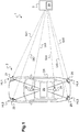
- a system 1 according to an embodiment of the invention is shown in figure 1 .
- the system comprises an array 2 and an electronic device 3, the system being configured to perform distance measurements between the array and the electronic device and to locate the electronic device 3.
- the array 2 is arranged on an automotive vehicle CR, for instance here a car, and the electronic device 3 is an electronic key of the vehicle, or key fob.
- the array may be arranged anywhere, such as in or on another type of vehicle, in a room, outside, etc. and the electronic device may be of any kind, for instance a smartphone, an electronic watch, or a tag having no other function than that of being located .
- the array 2 comprises a central unit 20, for instance a computer or an electronic circuit comprising a microcontroller, and a plurality of anchors 21 to 26, that is to say a programmable transceiver unit, configured to communicate with the central unit 20.
- a central unit 20 for instance a computer or an electronic circuit comprising a microcontroller, and a plurality of anchors 21 to 26, that is to say a programmable transceiver unit, configured to communicate with the central unit 20.
- a first anchor 21 and a second anchor 22 are respectively arranged near a front right headlight HL1 and a front left headlight HL2 of the car CR
- a third anchor 23 is arranged in a front part of the interior of the car CR, for instance between the driver seat and the front passenger seat
- a fourth anchor 24 is arranged in a rear part of the interior of the car CR
- a fifth anchor 25 and a sixth anchor 26 are respectively arranged near a left rear headlight HL3 and a right rear headlight HL4 of a car.
- the anchors 21 to 26 are directly and electrically connected to the central unit 20 so as to be able to communicate with the central unit.
- the anchors are connected to the central unit via CAN (Controller Area Network) buses or LIN (Local Interconnect Network) buses .
- the array 2 is configured to emit and receive radio signals via its anchors 21 to 26.
- the electronic device 3 is a battery-operated device comprising an electronic receiving circuit 30, for instance here an integrated circuit comprising an antenna, and is configured to emit and receive radio signals. More specifically, the electronic device 3 is configured to establish individual (here short-range) communication links Lk1 to Lk6 with the array 2 respectively via the anchors 21 to 26, that is to say communication links at a distance inferior to 100 meters.
- the electronic device is either in a first configuration in which the receiving circuit 30 is deactivated or in a second configuration in which the receiving circuit 30 is configured to detect and receive signals
- the array 2 and the device 3 are configured to communicate according to the Ultra Wide Band Technology (UWB technology), which comprise communications with signals having a very low power spectral density over bandwidth broader than 500 MHz.
- UWB technology comprises communications with signals having a very low power spectral density over bandwidth broader than 500 MHz.
- the UWB technology is suitable for short range communications and is advantageous because it does not interfere with conventional transmission technologies
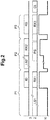
- Figure 2 is a chronogram schematically illustrating an elementary communication between the electronic device 3 and the array 2, that is, a communication between the electronic device 3 and only one of the anchors, and the current consumption Ic of the electronic device 3 during this elementary communication.
- This elementary communication may be part of a communication cycle involving a plurality of elementary communications between the anchors and the electronic device 3, as it will be described below.
- the electronic device 3 initiates the communication by broadcasting an initiation signal, or initiation frame.
- the anchors performs initially an initiation listening LS1 in which it waits for a detection of the initiation signal and, after having detected the initiation signal, it performs an initiation reception Rx1 of the initiation signal.
- the duration of the initiation listening LS1 may be variable and is limited to a first predetermined time period after which the antenna stops listening. For example, the first predetermined time period is equal to 1 millisecond.
- the electronic device 3 consumes a current of 110 milliamperes.
- the electronic device 3 which is in the second configuration, performs a reply listening LS2 in order to detect a reply signal from the anchor.
- the electronic device 3 may be configured to detect a header frame of the reply signal.
- the duration of the reply listening LS2 may be variable and is limited to a second predetermined time period after which the electronic device stops listening. For example, the predetermined time period is equal to 60 microsecond.
- the anchor proceeds to an emission PS of a reply signal to the electronic device 3 in order to facilitate distance measurement.
- This reply signal contains, among others, time synchronization information that allows the antenna and the electronic device 3 to temporally synchronize-[
- the electronic device 3 Upon detection of the reply signal, the electronic device 3 performs a reply reception RX2 in order to process the reply signal.
- the current consumed by the electronic device during the reply phase P2 is equal to 80 milliamperes during the reply listening, and 110 milliamperes during the reply reception. This current is mainly consumed by the receiving circuit 30.
- the receiving circuit consumes a current of 80 milliamperes during the predetermined period of 60 microseconds. This current consumption is therefore lost.
- a final phase P3 which is a last phase of the communication between the array and the electronic device, the electronic device 3 proceeds to a final broadcast RB during which it broadcasts a final signal to the array 2, said final signal finalizes the communication cycle and it comprises time information about when the reply signal has been received by the electronic device 3.
- the array 2 via the anchor, performs a final receiving RX3 of said final signal. Based on the time information contained in the final signal, the anchor performs a calculation CL to determine the distance between itself and the electronic device 3, for instance by using conventional time of flight technics.
- the electronic device may be configured to perform the calculation CL and to send the result in the final signal during the final broadcast RB.
- the current consumed by the electronic device in the second configuration during the final phase P3 is equal to 110 milliamperes.
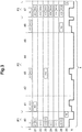
- Figure 3 illustrates an embodiment of the method according to the invention by showing a chronogram of a communication cycle 4 between the array 2 and the electronic device 3, at the end of which a position of the electronic device 3 is determined by the central unit 20. Although only one communication cycle 4 is shown on figure 3 , the method according to the invention may comprise several successive cycles. Figure 3 also illustrate the current consumption Ic of the electronic device 3 during this communication cycle 4.
- the communication cycle 4 is divided in several time slots and
- the initiation phase P1, the reply phase P2 and the final phase P3 are common to all the anchors.
- all the time slots have the same duration, here a duration of 1.175 milliseconds, but in alternative the times slots may have different durations.
- Each time slots of the reply phase is allocated to a distinct anchor.
- the second, third, fourth, fifth, sixth and seventh time slot are pre-allocated respectively to the first, second, third, fourth, fifth and sixth anchors.
- This allocation is a default allocation, and the central unit is configured to change this allocation if needed.
- the electronic device 3 proceeds to the initiation signal in order initiate the communication cycle 4.
- the anchors 21 to 26 perform several initiation listenings, respectively LS11 to LS16, during which each anchor is configured to wait for a detection of the initiation signal. Then, when an anchor detects the initiation signal, it proceeds to an initiation reception in which said initiation signal is received by the anchor and processed. At the end of the initiation phase, each anchor transmits a reception status of its respective initiation reception to the central unit 20, that is to say an information about the success or failure of its respective initiation reception.
- Each anchor is configured to stop the initiation listening after the first predetermined time period if the initiation signal is not received.
- the second anchor 22, the fourth anchor 24 and the fifth anchor 25 have not received the initiation signal and their respective initiation listening LS2, LS4 and LS5 are interrupted after the first predetermined time period. Therefore, they do not perform the initiation receptions, and in this example only the first anchor 21, the third anchor 23 and the sixth anchor 26 perform the initiation receptions respectively RX11, RX13 and RX16.
- the initiation listening may be longer or shorter. This difference may be caused by the configuration of the environment of the array 2, particularly by obstacle placed between the electronic device 3 and the anchors, for instance here people, such as passerby or passengers of the car CR.
- the central unit 20 proceeds to an election EL of some of the time slots, for instance in this embodiment three elected time slots, here the second time slot 41, the fourth time slot 43, and the seventh time slot 46, during which the electronic device 3 will operate in the second configuration.
- the central unit in order to elect the three time slots, proceed to a preliminary election of some of the anchors, for instance here the three preliminary elected anchors 21, 23 and 26 and elects the times slot allocated to these preliminary elected anchors.
- the preliminary election is based on the reception status of the initiation receptions. Because the second, fourth and fifth anchors 22, 24 and 25 did not receive the initiation signal, they are not preliminary elected. It would be possible that the central unit 20 preliminary elects only some of the anchors which receive the initiation signal, for instance based on the power of the received signal. The central unit may also fund the preliminary election on a random selection among the anchors having received the initiation signal, or on a random selection among all the anchors.
- the central unit 20 may choose any number of preliminary elected antennas, a number of at least two antennas is preliminary elected in order to ensure a locating of the electronic device 3, and more preferably a number of at least four antennas to improve the precision of the locating.
- the central unit 20 In order to perform a locating of the electronic device 3, the central unit 20 establishes a time slots map comprising information on which time slots are elected and which time slots are not elected.
- the electronic 3 device operate in the second configuration and the first anchor 21 performs a first emission PS1 of a first reply signal to the electronic device 3, said first reply signal comprising the slot map, and the electronic device 3 performs a first reply listening LS21 during which it waits for a detection of the first reply signal from the first anchor 21.
- the electronic device 3 Upon detection of the first reply signal, the electronic device 3 performs a first reply reception Rx21 of the reply signal.
- the electronic device 3 which possesses, thanks to the slot map, information about the non-election of the next time slot, here the third time slot 42, start to operates in the first configuration, that is, it deactivate the receiving circuit 30. Therefore, during the third time slot 42, the receiving circuit 30 will consume no current and the electronic device 3 will therefore consume a low current, for instance a current inferior to 5 milliamperes.
- the array 2 may be configured to send a reply signal despite the electronic device being in the first configuration. In this alternative, the third reply signal would not be received.
- the electronic device 3 then switches into the second configuration, that is to say activate the receiving circuit 30, for the next elected time slot, here the fourth time slot 43, according to the previously received time slots map and perform a second reply listening LS22.
- the third anchor 23 performs a second emission PS2 of a second reply signal; in the present example, said second reply signal does not contain the time slots map since it has already been sent to the electronic device 3 during the second time slot 41.
- the electronic device 3 Upon detection of the second reply signal, the electronic device 3 performs a second reply reception RX22 of the second reply signal.
- the electronic device operate in the first configuration for the next non allocated time slots, here the fifth and sixth time slot 44 and 45 and switches into the second configuration for next elected time slot, here the seventh time slot 46, during which the sixth anchor performs a third emission PS3 of a third reply signal and the electronic device 3 performs a third reply listening LS23 and a third reply reception Rx3 of the third reply signal.
- the electronic device 3 performs the final broadcasting RB of the final signal, said final signal comprising in this embodiment information on when the first, second and third reply signals have been received by the electronic device 3.
- the final signal may be received by any anchor of the array 2. Therefore, during the final phase, each anchor, respectively 21 to 26, performs a final listening, respectively LS31 to LS36, of the final signal. In this embodiment, all the anchors detect and perform a final reception, respectively RX31, RX32, RX33, RX 34, RX35, RX36 the final signal.
- each anchor is able to perform a calculation CL to determine distance between itself and the electronic device 3, and to transmit the result of the calculation, that is to say the distance value, to the central unit 20 so the central unit 20 can determine a location of the electronic device 3, for instance by trilateration.
- the electronic device 3 may be configured to perform the calculation CL, to determine its location and to send its location in the final signal during the final broadcasting RB.
- the locating process according to the invention may comprise a plurality of cycle, in order to increase the precision of the locating and/or to follow movements of the electronic device 3.
- the elected anchors may of course be different from a cycle to another.
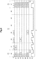
- Figure 4 shows another embodiment of the invention, according to which no slot map is sent to the electronic device 3.
- the election EL comprises an election of the earliest time slots of the reply phase P2, that is to say the second time slot 41, the third time slot 42 and the fourth time slot 43.
- the central unit performs a modification AL of the allocation of the time slots and allocates the second time slot 41, the third time slot 42 and the fourth time slot 43 respectively to the first anchor 21, the third anchor 23 and the sixth anchor 26.
- the three anchors 21, 23 and 26 are preliminary elected by the central unit 20 based on their respective reception status.
- the anchors perform respectively the first emission PS1 of the first reply signal, the second emission PS2 of the second reply signal and the third emission PS3 of the third reply signal, and during each of these time slot, the electronic device (3) which operates in the second configuration, performs the corresponding reply listenings LS21, LS22, LS23 and the corresponding reply receptions RX21, RX22, and RX23.
- the last anchor here the sixth anchor 26, performs the third emission PS3, or last emission, of the third reply signal, or here the last reply signal, said last reply signal comprising a deactivation command.
- the electronic device 3 of this embodiment is configured, in response to the deactivation command, to operate in the first configuration until the end of the reply phase P2, and to switch back to the second configuration for the final phase, that is to say for the eighth time slot 47.
- the electronic device 3 is configured to switch to the second configuration after a time period corresponding to the sum of the lengths of the non-elected time slots.
- the final phase P3 of this embodiment is carried out in a similar way to that described above with reference to figure 3 .
- FIG. 5 Another embodiment is illustrated on figure 5 .
- the method according to this embodiment does not comprise an election of time slots.
- the three anchors 21, 23 and 26 are preliminary elected by the central unit 20 based on the quality of the initiation signal received by each anchor, and only the preliminary elected anchor will send a reply signal.
- the central unit changes the allocation of the time slots and allocate the earliest time slots of the reply phase P2, here second time slot 41, the third time slot 42 and the fourth time slot 43 respectively to the preliminary elected anchor, here the first anchor 21, the third anchor 23 and the sixth anchor 26.
- the electronic device 3 is configured to operate in the first configuration until the final phase P3 if no reply signal is detected after the second predetermined time period during a time slot.
- the electronic device which operates in the second configuration performs a fourth reply listening LS24 in which it waits for a detection of a reply signal during the predetermined time period and then switch to the first configuration because no reply signal is detected.
- the electronic device 3 switch back to the second configuration for the final phase P3, which is carried out in a similar way to that described above with reference to figure 3 , and the central unit performs a calculation CL for determining the location of the electronic device 3.
- the reply phase is simplified because no command is sent to the electronic device via the reply signal.
- the invention is not limited to the embodiments described above, and although embodiment in which the array comprises six anchors have been described, the array may comprise any number of anchors and consequently, the reply phase P2 may comprise any number of time slots.
Landscapes
- Engineering & Computer Science (AREA)
- Radar, Positioning & Navigation (AREA)
- Remote Sensing (AREA)
- Physics & Mathematics (AREA)
- General Physics & Mathematics (AREA)
- Computer Networks & Wireless Communication (AREA)
- Signal Processing (AREA)
- Mobile Radio Communication Systems (AREA)
Abstract
Description
- The invention relates to the domains of wireless communication and mobile electronic device, notably to the domain of the radiolocating systems.
- More precisely the invention relates to a method for locating an electronic device and to a corresponding system, a corresponding array and a corresponding electronic device.
- Some automotive vehicles may comprise a wireless system that allows a user in possession of a wireless electronic device, for instance a key, a key fob, a card or a mobile phone, to access or start the vehicle by holding say wireless electronic device in the vicinity of the vehicle. For instance, such a system may unlock a specific door of the vehicle or start the vehicle depending on the location of the user holding the wireless electronic device. Several solutions exist to locate a wireless electronic device.
- A well-known solution comprises the use of an array comprising a central unit connected to several anchors arranged at several positions in or on a vehicle, and configured to establish a wireless communication with the wireless device.
- As the wireless device is in the range of at least one anchor, it broadcasts a signal in order to notify its presence. Upon receiving this signal from the wireless electronic device, the central unit initiates a data exchange in which the anchors successively transmit signals to the wireless electronic device.
- The wireless electronic device then listens, processes and responds to each of these signals in order for the central unit to determine its location. For instance, the locating could be performed according to well-known methods as the Time-of-Flight method or the RSSI method (Received Signal Strength Indicator).
- However, depending on the arrangement of the anchors and/or the position of the wireless electronic device, it is possible that some anchors are not able to establish a connection with the wireless electronic device. Therefore, the wireless electronic device may listen in vain for a response from the anchor. As the listening generates a high current consumption and as the wireless electronic device operates on battery, this may be very inconvenient.
- Therefore, an object of the invention is to provide an energy efficient wireless communication method and system for locating a wireless electronic device.
- The above objects are achieved thanks to the invention by providing a method for locating an electronic device in the vicinity of an array comprising a central unit and a plurality of anchors connected to the central unit, the electronic device comprising a receiving circuit and having a first configuration in which the receiving circuit is deactivated and a second configuration in which the receiving circuit is configured to detect and receive signals, said method comprising, during at least a communication cycle comprising a plurality of time slots each allocated to a distinct anchor,
- emissions, via at least some of the anchors during their respective time slots, of respective reply signals,
- an operation of the electronic device in the first configuration during at least a time slot,
- an operation of the electronic device in the second configuration during at least another time slot during which the electronic device is configured to detect and receive a reply signal,
- a calculation of a location of the electronic device based on the reply signal received by the electronic device.
- Therefore, thanks to the invention, since the receiving circuit is deactivated during at least a time slot, a very low current is consumed by the electronic device during some of the time slots and the autonomy of the electronic device is thus increased. Moreover, since only some of the reply signals are required to locate the electronic device, the method according to the invention does not lead to a drop in the accuracy of the locating.
- According to an embodiment, the method comprises an election of some of the time slots of the plurality of time slots and, during the earliest time slot of the plurality of time slots,
- an operation of the electronic device in the second configuration,
- a first emission by a first anchor, of a first reply signal comprising a time slots map comprising information on which time slots are elected,
- an operation of the electronic device into the first configuration during the non-elected time slots according to the time slots map and
- an operation of the electronic device into the second configuration during the elected time slots according to the time slots map.
- Therefore, it is possible to better distribute current consumption during the communication cycle. This is notably advantageous when the power supply of the electronic device comprises a decoupling capacitor which has therefore more time to reload between the emissions. Consequently, a smaller capacitor may be used, reducing the size and cost of the electronic device, and the method may comprise more time slots, that is to say the array may comprise more anchors.
- According to an embodiment, the method comprises
- a reception, by at least some of the anchors, of an initiation signal from the electronic device,
- a preliminary election of some of the anchors based on the quality of the reception of the initiation signal by the anchors,
- the election of the time slots allocated to the elected anchors.
- An election based on the quality of the initiation signal is very advantageous because it ensures that only the anchors which can establish the best communication with the electronic device will take part to the locating method.
- Therefore, the accuracy of the method is increased.
- According to an embodiment, the emissions comprise a last emission, by a last anchor, of a last reply signal comprising a deactivation command, the method comprising an operation of the electronic device into the first configuration at the detection of the deactivation command.
- Since the deactivation command is sent during the last emission, the array advantageously has more time to create a payload corresponding to the deactivation command.
- According to an embodiment, the method may comprise an operation of the electronic device in the first configuration if, after a predetermined time period during a time slot, no reply signal is detected by the electronic device in the second configuration.
- This advantageously simplify the method since no payload corresponding to a deactivation command needs to be created.
- The method may comprise a plurality of communication cycles.
- Several communication cycles may be useful to follow the possible movements of the electronic device, or to increase the accuracy of the locating by combining the results obtained during each cycle.
- According to another aspect, it is provided a system comprising an electronic device and an array comprising a central unit and a plurality of anchors electrically coupled to the central unit, the electronic device comprising a receiving circuit and having a first configuration in which the receiving circuit is deactivated and a second configuration in which the receiving circuit is configured to detect and receive signals, the array being configured to locate the electronic device during a communication cycle comprising a plurality of time slots each being allocated to an anchor. In this system,
- the central unit is configured to control emissions, via at least some of the anchors during their respective time slots, of respective reply signals,
- the electronic device is configured to operate in the first configuration during at least a time slot, and to operate in the second configuration during at least another time slot during which the electronic device is configured to detect and receive a reply signal,
- the system being configured to calculate a location of the electronic device based on the at least one reply signal received by the electronic device.
- According to an embodiment, the array is configured to elect some of the time slots of the plurality of time slots and,
- the electronic device is configured to be in the second configuration during the earliest time slot of the plurality of time slots,
- the array is configured to perform a first emission, via a first anchor, of a first reply signal comprising a time slots map comprising information on which time slots are elected,
- the electronic device is configured to operate in the first configuration during the non-elected time slots and to operate in the second configuration during the elected time slots according to the time slot map.
- According to an embodiment, the array is configured
- to perform a reception, by at least some of the anchors, of an initiation signal from the electronic device,
- to perform a preliminary election of some of the anchors based on the quality of the reception of the initiation signal by the anchors,
- to perform the election of the time slots allocated to the preliminary elected anchors.
- According to an embodiment, the array is configured to perform a last emission, by a last anchor, of a last reply signal comprising a deactivation command, the electronic device being configured to operate in the first configuration at the detection of the deactivation command.
- According to an embodiment, the electronic device is configured to operate in the first configuration if, after a predetermined time period during a time slot, no reply signal is detected by the electronic device operating in the second configuration.
- According to another aspect of the invention, it is provided an array comprising a central unit and a plurality of anchor electrically coupled to the central unit, the array being suitable for locating an electronic device during a communication cycle comprising a plurality of time slots each being allocated to an anchor, the array being configured to emit, via at least some of the anchors during their respective time slots, respective reply signals, the array being configured to calculate a location of the electronic device based on the at least one reply signal received by the electronic device.
- According to an embodiment, the array is configured
- to perform an election of some of the time slots of the plurality of time slots and wherein,
- to perform a first emission, via a first anchor, of a first reply signal comprising a time slots map comprising information on which time slots are elected,
- According to an embodiment, the array is configured to
- to perform a reception, by at least some of the anchors, of an initiation signal from the electronic device,
- to perform a preliminary election of some of the anchors based on the quality of the reception of the initiation signal by the anchors,
- to perform the election of the time slots allocated to the elected anchors.
- According to an embodiment, the array is configured to perform a last emission, by a last anchor, of a last reply signal comprising a deactivation command, the electronic device being configured to operate in the first configuration at the detection of the deactivation command.
- The array may be arranged on an automotive vehicle.
- According to another aspect, it is provided an electronic device comprising a receiving circuit and having a first configuration in which the receiving circuit is deactivated and a second configuration in which the receiving circuit is configured to detect and receive signals, configured to be located by an array comprising a central unit and a plurality of anchors electrically coupled to the central unit during a communication cycle comprising a plurality of time slots each being allocated to an anchor, said electronic device being configured to operate in the first configuration during at least a time slot, and to operate in the second configuration during at least another time slot during which the electronic device is configured to detect and receive a respective reply signal from an anchor.
- According to an embodiment, the electronic device is configured
- to operate in the second configuration during the earliest time slot of the plurality of time slots,
- to perform a first reception of a first reply signal comprising a time slots map comprising information regarding an election of some of the time slots by the array,
- to operate in the first configuration during the non-elected time slots and to operate in the first configuration during the elected time slots, according to the time slots map.
- According to an embodiment, the electronic device is configured to operate in the first configuration at the detection of a deactivation command.
- According to an embodiment, the electronic device is configured to operate in the first configuration if, after a predetermined time period operating in the second configuration during a time slot, no reply signal is detected.
- Other advantages and features of the invention will appear in the following detailed description of particular embodiments of the invention and on the accompanying drawings. It should be noted that the invention is not limited to the particular embodiments illustrated in the drawings; accordingly, it should be understood that where features mentioned in the claims are followed by reference signs, such signs are included solely for the purpose of enhancing the intelligibility of the claims and are in no way limiting on the scope of the claims.
- In the accompanying drawings:
-
figure 1 is a schematic view of a system according to an embodiment of the invention; -
figure 2 is a chronogram illustrating a communication between one anchor and an electronic device; -
figure 3 is a chronogram illustrating a method according to an embodiment of the invention; -
figure 4 is a chronogram illustrating a method according to a second embodiment of the invention; -
figure 5 is a chronogram illustrating a method according to a third embodiment of the invention. - A system 1 according to an embodiment of the invention is shown in
figure 1 . The system comprises anarray 2 and anelectronic device 3, the system being configured to perform distance measurements between the array and the electronic device and to locate theelectronic device 3. - In this particular embodiment, the
array 2 is arranged on an automotive vehicle CR, for instance here a car, and theelectronic device 3 is an electronic key of the vehicle, or key fob. However, this example is not at all limiting and the array may be arranged anywhere, such as in or on another type of vehicle, in a room, outside, etc. and the electronic device may be of any kind, for instance a smartphone, an electronic watch, or a tag having no other function than that of being located . - The
array 2 comprises acentral unit 20, for instance a computer or an electronic circuit comprising a microcontroller, and a plurality ofanchors 21 to 26, that is to say a programmable transceiver unit, configured to communicate with thecentral unit 20. - In this embodiment, a
first anchor 21 and asecond anchor 22 are respectively arranged near a front right headlight HL1 and a front left headlight HL2 of the car CR, athird anchor 23 is arranged in a front part of the interior of the car CR, for instance between the driver seat and the front passenger seat, afourth anchor 24 is arranged in a rear part of the interior of the car CR, and afifth anchor 25 and asixth anchor 26 are respectively arranged near a left rear headlight HL3 and a right rear headlight HL4 of a car. - For instance, here, the
anchors 21 to 26 are directly and electrically connected to thecentral unit 20 so as to be able to communicate with the central unit. For instance, the anchors are connected to the central unit via CAN (Controller Area Network) buses or LIN (Local Interconnect Network) buses . - The
array 2 is configured to emit and receive radio signals via itsanchors 21 to 26. - The
electronic device 3 is a battery-operated device comprising anelectronic receiving circuit 30, for instance here an integrated circuit comprising an antenna, and is configured to emit and receive radio signals. More specifically, theelectronic device 3 is configured to establish individual (here short-range) communication links Lk1 to Lk6 with thearray 2 respectively via theanchors 21 to 26, that is to say communication links at a distance inferior to 100 meters. The electronic device is either in a first configuration in which the receivingcircuit 30 is deactivated or in a second configuration in which the receivingcircuit 30 is configured to detect and receive signals - The
array 2 and thedevice 3 are configured to communicate according to the Ultra Wide Band Technology (UWB technology), which comprise communications with signals having a very low power spectral density over bandwidth broader than 500 MHz. The UWB technology is suitable for short range communications and is advantageous because it does not interfere with conventional transmission technologies -
Figure 2 is a chronogram schematically illustrating an elementary communication between theelectronic device 3 and thearray 2, that is, a communication between theelectronic device 3 and only one of the anchors, and the current consumption Ic of theelectronic device 3 during this elementary communication. This elementary communication may be part of a communication cycle involving a plurality of elementary communications between the anchors and theelectronic device 3, as it will be described below. - Initially, during an initiation phase P1 the
electronic device 3 initiates the communication by broadcasting an initiation signal, or initiation frame. - The anchors performs initially an initiation listening LS1 in which it waits for a detection of the initiation signal and, after having detected the initiation signal, it performs an initiation reception Rx1 of the initiation signal. The duration of the initiation listening LS1 may be variable and is limited to a first predetermined time period after which the antenna stops listening. For example, the first predetermined time period is equal to 1 millisecond. During the initiation phase P1, the
electronic device 3 consumes a current of 110 milliamperes. - Then, during a reply phase P2, the
electronic device 3, which is in the second configuration, performs a reply listening LS2 in order to detect a reply signal from the anchor. For example, theelectronic device 3 may be configured to detect a header frame of the reply signal. The duration of the reply listening LS2 may be variable and is limited to a second predetermined time period after which the electronic device stops listening. For example, the predetermined time period is equal to 60 microsecond. - During the reply phase P2, the anchor proceeds to an emission PS of a reply signal to the
electronic device 3 in order to facilitate distance measurement. This reply signal contains, among others, time synchronization information that allows the antenna and theelectronic device 3 to temporally synchronize-[ - Upon detection of the reply signal, the
electronic device 3 performs a reply reception RX2 in order to process the reply signal. - The current consumed by the electronic device during the reply phase P2 is equal to 80 milliamperes during the reply listening, and 110 milliamperes during the reply reception. This current is mainly consumed by the receiving
circuit 30. - It should be noted that when the reply detection is not successful, the receiving circuit consume a current of 80 milliamperes during the predetermined period of 60 microseconds. This current consumption is therefore lost.
- During a final phase P3, which is a last phase of the communication between the array and the electronic device, the
electronic device 3 proceeds to a final broadcast RB during which it broadcasts a final signal to thearray 2, said final signal finalizes the communication cycle and it comprises time information about when the reply signal has been received by theelectronic device 3. - The
array 2, via the anchor, performs a final receiving RX3 of said final signal. Based on the time information contained in the final signal, the anchor performs a calculation CL to determine the distance between itself and theelectronic device 3, for instance by using conventional time of flight technics. - In alternative, the electronic device may be configured to perform the calculation CL and to send the result in the final signal during the final broadcast RB.
- The current consumed by the electronic device in the second configuration during the final phase P3 is equal to 110 milliamperes.
-
Figure 3 illustrates an embodiment of the method according to the invention by showing a chronogram of acommunication cycle 4 between thearray 2 and theelectronic device 3, at the end of which a position of theelectronic device 3 is determined by thecentral unit 20. Although only onecommunication cycle 4 is shown onfigure 3 , the method according to the invention may comprise several successive cycles.Figure 3 also illustrate the current consumption Ic of theelectronic device 3 during thiscommunication cycle 4. - The
communication cycle 4 is divided in several time slots and - the initiation phase P1 comprises a
first time slot 40, - the reply phase P2 comprises a
second time slot 41, athird time slot 42, afourth time slot 43, afifth time slot 44, asixth time slot 45, aseventh time slot 46 and - the final phase P3 comprises an
eighth time slot 46. - In this embodiment, the initiation phase P1, the reply phase P2 and the final phase P3 are common to all the anchors.
- Here, all the time slots have the same duration, here a duration of 1.175 milliseconds, but in alternative the times slots may have different durations.
- Each time slots of the reply phase is allocated to a distinct anchor. For instance, here, the second, third, fourth, fifth, sixth and seventh time slot are pre-allocated respectively to the first, second, third, fourth, fifth and sixth anchors. This allocation is a default allocation, and the central unit is configured to change this allocation if needed.
- During the initiation phase P1, the
electronic device 3 proceeds to the initiation signal in order initiate thecommunication cycle 4. - The
anchors 21 to 26 perform several initiation listenings, respectively LS11 to LS16, during which each anchor is configured to wait for a detection of the initiation signal. Then, when an anchor detects the initiation signal, it proceeds to an initiation reception in which said initiation signal is received by the anchor and processed. At the end of the initiation phase, each anchor transmits a reception status of its respective initiation reception to thecentral unit 20, that is to say an information about the success or failure of its respective initiation reception. - Each anchor is configured to stop the initiation listening after the first predetermined time period if the initiation signal is not received. For instance, on
figure 3 , thesecond anchor 22, thefourth anchor 24 and thefifth anchor 25 have not received the initiation signal and their respective initiation listening LS2, LS4 and LS5 are interrupted after the first predetermined time period. Therefore, they do not perform the initiation receptions, and in this example only thefirst anchor 21, thethird anchor 23 and thesixth anchor 26 perform the initiation receptions respectively RX11, RX13 and RX16. - Depending on the anchor, the initiation listening may be longer or shorter. This difference may be caused by the configuration of the environment of the
array 2, particularly by obstacle placed between theelectronic device 3 and the anchors, for instance here people, such as passerby or passengers of the car CR. - Then, the
central unit 20 proceeds to an election EL of some of the time slots, for instance in this embodiment three elected time slots, here thesecond time slot 41, thefourth time slot 43, and theseventh time slot 46, during which theelectronic device 3 will operate in the second configuration. - In this embodiment, in order to elect the three time slots, the central unit proceed to a preliminary election of some of the anchors, for instance here the three preliminary elected
anchors fifth anchors central unit 20 preliminary elects only some of the anchors which receive the initiation signal, for instance based on the power of the received signal. The central unit may also fund the preliminary election on a random selection among the anchors having received the initiation signal, or on a random selection among all the anchors. - Although the
central unit 20 may choose any number of preliminary elected antennas, a number of at least two antennas is preliminary elected in order to ensure a locating of theelectronic device 3, and more preferably a number of at least four antennas to improve the precision of the locating. - In order to perform a locating of the
electronic device 3, thecentral unit 20 establishes a time slots map comprising information on which time slots are elected and which time slots are not elected. - Then, during the earliest time slot of the reply phase P2, here during the
second time slot 41, the electronic 3 device operate in the second configuration and thefirst anchor 21 performs a first emission PS1 of a first reply signal to theelectronic device 3, said first reply signal comprising the slot map, and theelectronic device 3 performs a first reply listening LS21 during which it waits for a detection of the first reply signal from thefirst anchor 21. Upon detection of the first reply signal, theelectronic device 3 performs a first reply reception Rx21 of the reply signal. - At the end of the
second time slot 41, that is to say at the end of the first elected time slot, theelectronic device 3 which possesses, thanks to the slot map, information about the non-election of the next time slot, here thethird time slot 42, start to operates in the first configuration, that is, it deactivate the receivingcircuit 30. Therefore, during thethird time slot 42, the receivingcircuit 30 will consume no current and theelectronic device 3 will therefore consume a low current, for instance a current inferior to 5 milliamperes. - During the
third time slot 42, which is a non-elected time slot, no reply signal is sent. In alternative, thearray 2 may be configured to send a reply signal despite the electronic device being in the first configuration. In this alternative, the third reply signal would not be received. - The
electronic device 3 then switches into the second configuration, that is to say activate the receivingcircuit 30, for the next elected time slot, here thefourth time slot 43, according to the previously received time slots map and perform a second reply listening LS22. Thethird anchor 23 performs a second emission PS2 of a second reply signal; in the present example, said second reply signal does not contain the time slots map since it has already been sent to theelectronic device 3 during thesecond time slot 41. Upon detection of the second reply signal, theelectronic device 3 performs a second reply reception RX22 of the second reply signal. - Then, according to the time slots map and in a similar way to what has been previously described, the electronic device operate in the first configuration for the next non allocated time slots, here the fifth and
sixth time slot seventh time slot 46, during which the sixth anchor performs a third emission PS3 of a third reply signal and theelectronic device 3 performs a third reply listening LS23 and a third reply reception Rx3 of the third reply signal. - Therefore, thanks to this method, a very low current is consumed during the non-elected time slots.
- During the final phase P3, here during the
eighth time slot 47, theelectronic device 3 performs the final broadcasting RB of the final signal, said final signal comprising in this embodiment information on when the first, second and third reply signals have been received by theelectronic device 3. - The final signal may be received by any anchor of the
array 2. Therefore, during the final phase, each anchor, respectively 21 to 26, performs a final listening, respectively LS31 to LS36, of the final signal. In this embodiment, all the anchors detect and perform a final reception, respectively RX31, RX32, RX33, RX 34, RX35, RX36 the final signal. - Based on the time information contained in the final signal, each anchor is able to perform a calculation CL to determine distance between itself and the
electronic device 3, and to transmit the result of the calculation, that is to say the distance value, to thecentral unit 20 so thecentral unit 20 can determine a location of theelectronic device 3, for instance by trilateration. - In alternative, the
electronic device 3 may be configured to perform the calculation CL, to determine its location and to send its location in the final signal during the final broadcasting RB. - Although only one
communication cycle 4 is shown onfigure 3 , the locating process according to the invention may comprise a plurality of cycle, in order to increase the precision of the locating and/or to follow movements of theelectronic device 3. Moreover, the elected anchors may of course be different from a cycle to another. -
Figure 4 shows another embodiment of the invention, according to which no slot map is sent to theelectronic device 3. - In this embodiment, the election EL comprises an election of the earliest time slots of the reply phase P2, that is to say the
second time slot 41, thethird time slot 42 and thefourth time slot 43. - In this embodiment, the central unit performs a modification AL of the allocation of the time slots and allocates the
second time slot 41, thethird time slot 42 and thefourth time slot 43 respectively to thefirst anchor 21, thethird anchor 23 and thesixth anchor 26. - In this embodiment, the three
anchors central unit 20 based on their respective reception status. - During the second, third and
fourth time slots - During the latest elected time slot, here during the
fourth time slot 43, the last anchor, here thesixth anchor 26, performs the third emission PS3, or last emission, of the third reply signal, or here the last reply signal, said last reply signal comprising a deactivation command. - The
electronic device 3 of this embodiment is configured, in response to the deactivation command, to operate in the first configuration until the end of the reply phase P2, and to switch back to the second configuration for the final phase, that is to say for theeighth time slot 47. - For instance, here, the
electronic device 3 is configured to switch to the second configuration after a time period corresponding to the sum of the lengths of the non-elected time slots. - Therefore, a very low current is consumed during the non-elected time slots.
- The final phase P3 of this embodiment is carried out in a similar way to that described above with reference to
figure 3 . - Another embodiment is illustrated on
figure 5 . - The method according to this embodiment does not comprise an election of time slots.
- In this embodiment, the three
anchors central unit 20 based on the quality of the initiation signal received by each anchor, and only the preliminary elected anchor will send a reply signal. - In this embodiment, the central unit changes the allocation of the time slots and allocate the earliest time slots of the reply phase P2, here
second time slot 41, thethird time slot 42 and thefourth time slot 43 respectively to the preliminary elected anchor, here thefirst anchor 21, thethird anchor 23 and thesixth anchor 26. - In this embodiment, the
electronic device 3 is configured to operate in the first configuration until the final phase P3 if no reply signal is detected after the second predetermined time period during a time slot. - For instance in this embodiment, during the
fifth time slot 44, which is not allocated to a preliminary elected anchor, the electronic device which operates in the second configuration performs a fourth reply listening LS24 in which it waits for a detection of a reply signal during the predetermined time period and then switch to the first configuration because no reply signal is detected. - The
electronic device 3 switch back to the second configuration for the final phase P3, which is carried out in a similar way to that described above with reference tofigure 3 , and the central unit performs a calculation CL for determining the location of theelectronic device 3. - Therefore, the reply phase is simplified because no command is sent to the electronic device via the reply signal.
- The invention is not limited to the embodiments described above, and although embodiment in which the array comprises six anchors have been described, the array may comprise any number of anchors and consequently, the reply phase P2 may comprise any number of time slots.
Claims (15)
- Method for locating an electronic device (3) in the vicinity of an array (2) comprising a central unit (20) and a plurality of anchors (21, 22, 23, 24, 25, 26) connected to the central unit (20), the electronic device (3) comprising a receiving circuit (30) and having a first configuration in which the receiving circuit (30) is deactivated and a second configuration in which the receiving circuit (30) is configured to detect and receive signals, said method comprising, during at least a communication cycle (4) comprising a plurality of time slots (41, 42, 43, 44, 45, 46, 47) each allocated to a distinct anchor,- emissions (PS1, PS2, PS3), via at least some of the anchors during their respective time slots, of respective reply signals,- an operation of the electronic device (3) in the first configuration during at least a time slot,- an operation of the electronic device (3) in the second configuration during at least another time slot during which the electronic device is configured to detect and receive a reply signal,a calculation (CL) of a location of the electronic device (3) based on the reply signal received by the electronic device (3).
- Method according to claim 1, comprising an election (EL) of some of the time slots (41, 43, 46) of the plurality of time slots and, during the earliest time slot (41) of the plurality of time slots,- an operation of the electronic device (3) in the second configuration,- a first emission (PS1) by a first anchor (21), of a first reply signal comprising a time slots map comprising information on which time slots are elected,- an operation of the electronic device (3) into the first configuration during the non-elected time slots according to the time slots map and- an operation of the electronic device (3) into the second configuration during the elected time slots according to the time slots map.
- Method according to claim 2, comprising- a reception, by at least some of the anchors, of an initiation signal from the electronic device (3),- a preliminary election of some of the anchors based on the quality of the reception of the initiation signal by the anchors,- the election (EL) of the time slots allocated to the elected anchors.
- Method according to claim 1, wherein the emissions comprise a last emission (PS3), by a last anchor (26), of a last reply signal comprising a deactivation command, the method comprising an operation of the electronic device (3) into the first configuration at the detection of the deactivation command.
- Method according to claim 1, comprising an operation of the electronic device (3) in the first configuration if, after a predetermined time period during a time slot, no reply signal is detected by the electronic device (3) in the second configuration.
- Method according to any of the preceding claims, comprising a plurality of communication cycles (4).
- System comprising an electronic device (3) and an array (2) comprising a central unit (20) and a plurality of anchors (21, 22, 23, 24, 25, 26) electrically coupled to the central unit (20), the electronic device comprising a receiving circuit and having a first configuration in which the receiving circuit is deactivated and a second configuration in which the receiving circuit is configured to detect and receive signals, the array being configured to locate the electronic device during a communication cycle comprising a plurality of time slots each being allocated to an anchor, wherein- the central unit (20) is configured to control emissions (PS1, PS2, PS3), via at least some of the anchors during their respective time slots, of respective reply signals,- the electronic device (3) is configured to operate in the first configuration during at least a time slot, and to operate in the second configuration during at least another time slot during which the electronic device is configured to detect and receive a reply signal,the system (1) being configured to calculate a location of the electronic device (3) based on the at least one reply signal received by the electronic device (3).
- System according to claim 7, wherein the array (2) is configured to elect some of the time slots (41, 43, 46) of the plurality of time slots and wherein,- the electronic device (3) is configured to be in the second configuration during the earliest time slot (41) of the plurality of time slots,- the array is configured to perform a first emission, via a first anchor, of a first reply signal comprising a time slots map comprising information on which time slots are elected,- the electronic device is configured to operate in the first configuration during the non-elected time slots and to operate in the second configuration during the elected time slots according to the time slots map.
- System according to claim 8, wherein the array (2) is configured- to perform a reception, by at least some of the anchors (21, 23, 26), of an initiation signal from the electronic device (3),- to perform a preliminary election of some of the anchors based on the quality of the reception of the identification signal by the anchors,- to perform the election (EL) of the time slots allocated to the preliminary elected anchors.
- System according to claim 8, wherein the array (2) is configured to perform a last emission (PS3), by a last anchor (26), of a last reply signal comprising a deactivation command, the electronic device (3) being configured to operate in the first configuration at the detection of the deactivation command.
- System according to claim 8, wherein the electronic device (3) is configured to operate in the first configuration if, after a predetermined time period during a time slot, no reply signal is detected by the electronic device (3) operating in the second configuration.
- Electronic device comprising a receiving circuit and having a first configuration in which the receiving circuit is deactivated and a second configuration in which the receiving circuit is configured to detect and receive signals, configured to be located by an array comprising a central unit and a plurality of anchors electrically coupled to the central unit (20) during a communication cycle comprising a plurality of time slots each being allocated to an anchor, said electronic device (3) being configured to operate in the first configuration during at least a time slot, and to operate in the second configuration during at least another time slot during which the electronic device is configured to detect and receive a respective reply signal from an anchor.
- Electronic device according to claim 12, configured- to operate in the second configuration during the earliest time slot (41) of the plurality of time slots,- to perform a first reception of a first reply signal comprising a time slots map comprising information regarding an election of some of the time slots by the array (2),- to operate in the first configuration during the non-elected time slots and to operate in the first configuration during the elected time slots, according to the time slots map.
- Electronic device according to claim 12, configured to operate in the first configuration at the detection of a deactivation command.
- Electronic device according to claim 12, configured to operate in the first configuration if, after a predetermined time period operating in the second configuration during a time slot, no reply signal is detected.
Priority Applications (3)
| Application Number | Priority Date | Filing Date | Title |
|---|---|---|---|
| EP19214562.1A EP3836573A1 (en) | 2019-12-09 | 2019-12-09 | Method for locating an electronic device, corresponding system and corresponding electronic device |
| PCT/EP2020/084331 WO2021115885A1 (en) | 2019-12-09 | 2020-12-02 | Method for locating an electronic device, corresponding system and corresponding electronic device |
| US17/783,482 US12455340B2 (en) | 2019-12-09 | 2020-12-02 | Method for locating an electronic device, corresponding system and corresponding electronic device |
Applications Claiming Priority (1)
| Application Number | Priority Date | Filing Date | Title |
|---|---|---|---|
| EP19214562.1A EP3836573A1 (en) | 2019-12-09 | 2019-12-09 | Method for locating an electronic device, corresponding system and corresponding electronic device |
Publications (1)
| Publication Number | Publication Date |
|---|---|
| EP3836573A1 true EP3836573A1 (en) | 2021-06-16 |
Family
ID=68840978
Family Applications (1)
| Application Number | Title | Priority Date | Filing Date |
|---|---|---|---|
| EP19214562.1A Pending EP3836573A1 (en) | 2019-12-09 | 2019-12-09 | Method for locating an electronic device, corresponding system and corresponding electronic device |
Country Status (3)
| Country | Link |
|---|---|
| US (1) | US12455340B2 (en) |
| EP (1) | EP3836573A1 (en) |
| WO (1) | WO2021115885A1 (en) |
Cited By (2)
| Publication number | Priority date | Publication date | Assignee | Title |
|---|---|---|---|---|
| EP4167203A1 (en) * | 2021-10-13 | 2023-04-19 | Hyundai Mobis Co., Ltd. | Lock control apparatus for vehicle and method of controlling the same |
| EP4343376A3 (en) * | 2022-08-30 | 2024-05-29 | Apple Inc. | One-to-many and many-to-many ranging using nba-mms uwb protocols |
Citations (2)
| Publication number | Priority date | Publication date | Assignee | Title |
|---|---|---|---|---|
| US20170103594A1 (en) * | 2015-10-13 | 2017-04-13 | Hyundai Motor Company | Smart key controller for vehicle routing pattern-based variable control and method thereof |
| GB2551861A (en) * | 2016-07-01 | 2018-01-03 | Lear Corp | Passive entry systems employing time of flight distance measurements |
Family Cites Families (10)
| Publication number | Priority date | Publication date | Assignee | Title |
|---|---|---|---|---|
| US20100304690A1 (en) * | 2009-05-29 | 2010-12-02 | Gm Global Technology Operations, Inc. | Method of passively detecting an approach to a vehicle |
| US9852560B2 (en) * | 2013-03-08 | 2017-12-26 | Lear Corporation | Vehicle remote function system and method for effectuating vehicle operations based on vehicle FOB movement |
| US9086879B2 (en) * | 2013-07-26 | 2015-07-21 | GM Global Technology Operations LLC | Methods and apparatus for optimizing battery life in a remote device |
| US12077997B2 (en) * | 2015-09-12 | 2024-09-03 | Adac Plastics, Inc. | Motor vehicle gesture access system including powered door speed control |
| WO2017062980A1 (en) * | 2015-10-08 | 2017-04-13 | Voxx International Corporation | System and method for micro-locating and communicating with a portable vehicle control device |
| US10559149B1 (en) * | 2018-10-08 | 2020-02-11 | Nxp B.V. | Dynamic anchor pre-selection for ranging applications |
| WO2020198713A1 (en) * | 2019-03-27 | 2020-10-01 | Apple Inc. | Assistance information indication for rat and interface selection for new radio vehicle-to-everything (v2x) |
| US20200307555A1 (en) * | 2019-04-01 | 2020-10-01 | Ford Global Technologies, Llc | Key fob utilization for vehicle remote park-assist |
| US11021134B2 (en) * | 2019-04-29 | 2021-06-01 | Hyundai Mobis Co., Ltd. | Method of controlling smart key |
| US11565658B2 (en) * | 2019-08-07 | 2023-01-31 | Keep Technologies, Inc. | Windshield-mounted vehicle anti-theft apparatus and methods for using same |
-
2019
- 2019-12-09 EP EP19214562.1A patent/EP3836573A1/en active Pending
-
2020
- 2020-12-02 WO PCT/EP2020/084331 patent/WO2021115885A1/en not_active Ceased
- 2020-12-02 US US17/783,482 patent/US12455340B2/en active Active
Patent Citations (2)
| Publication number | Priority date | Publication date | Assignee | Title |
|---|---|---|---|---|
| US20170103594A1 (en) * | 2015-10-13 | 2017-04-13 | Hyundai Motor Company | Smart key controller for vehicle routing pattern-based variable control and method thereof |
| GB2551861A (en) * | 2016-07-01 | 2018-01-03 | Lear Corp | Passive entry systems employing time of flight distance measurements |
Cited By (6)
| Publication number | Priority date | Publication date | Assignee | Title |
|---|---|---|---|---|
| EP4167203A1 (en) * | 2021-10-13 | 2023-04-19 | Hyundai Mobis Co., Ltd. | Lock control apparatus for vehicle and method of controlling the same |
| US12012072B2 (en) | 2021-10-13 | 2024-06-18 | Hyundai Mobis Co., Ltd. | Lock control apparatus for vehicle and method of controlling the same |
| US12017611B2 (en) | 2021-10-13 | 2024-06-25 | Hyundai Mobis Co., Ltd. | Lock control apparatus for vehicle and method of controlling the same |
| US12311879B2 (en) | 2021-10-13 | 2025-05-27 | Hyundai Mobis Co., Ltd. | Lock control apparatus for vehicle and method of controlling the same |
| EP4343376A3 (en) * | 2022-08-30 | 2024-05-29 | Apple Inc. | One-to-many and many-to-many ranging using nba-mms uwb protocols |
| US12574892B2 (en) | 2022-08-30 | 2026-03-10 | Apple Inc. | One-to-many and many-to-many ranging using NBA-MMS UWB protocols |
Also Published As
| Publication number | Publication date |
|---|---|
| WO2021115885A1 (en) | 2021-06-17 |
| US12455340B2 (en) | 2025-10-28 |
| US20230018938A1 (en) | 2023-01-19 |
Similar Documents
| Publication | Publication Date | Title |
|---|---|---|
| CN115552274B (en) | Position estimation system, position estimation method, vehicle communication device | |
| JP7183830B2 (en) | Vehicle localization system | |
| CN108337662B (en) | Method for adjusting the interference level of wireless communication from a first mobile station to a second mobile station | |
| US10013830B2 (en) | Method and smartkey system for reducing battery consumption | |
| US11740342B2 (en) | Method and apparatus for selecting a ranging anchor based on characteristics of communication between a connection anchor and a mobile electronic device | |
| CN111356080B (en) | RF system and method for implementing role switching of transceiver nodes | |
| CN110856140A (en) | Vehicle network sharing | |
| US12455340B2 (en) | Method for locating an electronic device, corresponding system and corresponding electronic device | |
| US11716778B2 (en) | System and method of determining real-time location | |
| CN110537085B (en) | Vehicle gateway system and communication method for communicating with ant-type radio device | |
| WO2023110268A1 (en) | Method and system for accessing a functionality of a vehicle via a mobile device | |
| US9813119B1 (en) | Passive wireless accessory switch pack | |
| US20210217259A1 (en) | System and Method For Communicating With A Vehicle | |
| CN110784850A (en) | Fleet-to-fleet network | |
| US10931153B2 (en) | Wireless electricity transmission system | |
| KR102932907B1 (en) | Uwb system in vehicle and method for opening and closing vehicle door | |
| WO2024048370A1 (en) | Occupant position estimation device and occupant position estimation method | |
| JP7008868B1 (en) | Wireless devices, wireless control methods, control circuits and storage media | |
| US12256432B2 (en) | On-vehicle ultra-wideband system and method | |
| CN118283571A (en) | A UWB-based vehicle communication method, device and computing equipment | |
| JP7563957B2 (en) | Wireless communication device and wireless communication system | |
| US20260016591A1 (en) | Distance measurement system and distancemeasurement method | |
| US20250389835A1 (en) | Method for determining a pose of another road user | |
| US20260126541A1 (en) | Non-line-of-sight object detection | |
| WO2025204034A1 (en) | A system and method for selecting devices for a location system |
Legal Events
| Date | Code | Title | Description |
|---|---|---|---|
| PUAI | Public reference made under article 153(3) epc to a published international application that has entered the european phase |
Free format text: ORIGINAL CODE: 0009012 |
|
| STAA | Information on the status of an ep patent application or granted ep patent |
Free format text: STATUS: THE APPLICATION HAS BEEN PUBLISHED |
|
| AK | Designated contracting states |
Kind code of ref document: A1 Designated state(s): AL AT BE BG CH CY CZ DE DK EE ES FI FR GB GR HR HU IE IS IT LI LT LU LV MC MK MT NL NO PL PT RO RS SE SI SK SM TR |
|
| STAA | Information on the status of an ep patent application or granted ep patent |
Free format text: STATUS: REQUEST FOR EXAMINATION WAS MADE |
|
| 17P | Request for examination filed |
Effective date: 20211213 |
|
| RBV | Designated contracting states (corrected) |
Designated state(s): AL AT BE BG CH CY CZ DE DK EE ES FI FR GB GR HR HU IE IS IT LI LT LU LV MC MK MT NL NO PL PT RO RS SE SI SK SM TR |
|
| RAP3 | Party data changed (applicant data changed or rights of an application transferred) |
Owner name: VALEO COMFORT AND DRIVING ASSISTANCE |
|
| P01 | Opt-out of the competence of the unified patent court (upc) registered |
Effective date: 20230528 |
|
| RAP3 | Party data changed (applicant data changed or rights of an application transferred) |
Owner name: VALEO COMFORT AND DRIVING ASSISTANCE |
|
| STAA | Information on the status of an ep patent application or granted ep patent |
Free format text: STATUS: EXAMINATION IS IN PROGRESS |
|
| 17Q | First examination report despatched |
Effective date: 20240202 |