EP3836519A1 - Mobile terminal - Google Patents
Mobile terminal Download PDFInfo
- Publication number
- EP3836519A1 EP3836519A1 EP19858234.8A EP19858234A EP3836519A1 EP 3836519 A1 EP3836519 A1 EP 3836519A1 EP 19858234 A EP19858234 A EP 19858234A EP 3836519 A1 EP3836519 A1 EP 3836519A1
- Authority
- EP
- European Patent Office
- Prior art keywords
- face
- groove
- image capturing
- capturing device
- mounting groove
- Prior art date
- Legal status (The legal status is an assumption and is not a legal conclusion. Google has not performed a legal analysis and makes no representation as to the accuracy of the status listed.)
- Granted
Links
Images



Classifications
-
- H—ELECTRICITY
- H04—ELECTRIC COMMUNICATION TECHNIQUE
- H04M—TELEPHONIC COMMUNICATION
- H04M1/00—Substation equipment, e.g. for use by subscribers
- H04M1/02—Constructional features of telephone sets
- H04M1/0202—Portable telephone sets, e.g. cordless phones, mobile phones or bar type handsets
- H04M1/026—Details of the structure or mounting of specific components
- H04M1/0264—Details of the structure or mounting of specific components for a camera module assembly
-
- H—ELECTRICITY
- H04—ELECTRIC COMMUNICATION TECHNIQUE
- H04M—TELEPHONIC COMMUNICATION
- H04M1/00—Substation equipment, e.g. for use by subscribers
- H04M1/02—Constructional features of telephone sets
- H04M1/0202—Portable telephone sets, e.g. cordless phones, mobile phones or bar type handsets
- H04M1/0254—Portable telephone sets, e.g. cordless phones, mobile phones or bar type handsets comprising one or a plurality of mechanically detachable modules
- H04M1/0256—Portable telephone sets, e.g. cordless phones, mobile phones or bar type handsets comprising one or a plurality of mechanically detachable modules wherein the modules are operable in the detached state, e.g. one module for the user interface and one module for the transceiver
-
- H—ELECTRICITY
- H04—ELECTRIC COMMUNICATION TECHNIQUE
- H04N—PICTORIAL COMMUNICATION, e.g. TELEVISION
- H04N23/00—Cameras or camera modules comprising electronic image sensors; Control thereof
- H04N23/50—Constructional details
- H04N23/55—Optical parts specially adapted for electronic image sensors; Mounting thereof
-
- H—ELECTRICITY
- H04—ELECTRIC COMMUNICATION TECHNIQUE
- H04N—PICTORIAL COMMUNICATION, e.g. TELEVISION
- H04N23/00—Cameras or camera modules comprising electronic image sensors; Control thereof
- H04N23/57—Mechanical or electrical details of cameras or camera modules specially adapted for being embedded in other devices
-
- H—ELECTRICITY
- H04—ELECTRIC COMMUNICATION TECHNIQUE
- H04M—TELEPHONIC COMMUNICATION
- H04M1/00—Substation equipment, e.g. for use by subscribers
- H04M1/72—Mobile telephones; Cordless telephones, i.e. devices for establishing wireless links to base stations without route selection
- H04M1/724—User interfaces specially adapted for cordless or mobile telephones
- H04M1/72403—User interfaces specially adapted for cordless or mobile telephones with means for local support of applications that increase the functionality
- H04M1/72409—User interfaces specially adapted for cordless or mobile telephones with means for local support of applications that increase the functionality by interfacing with external accessories
- H04M1/72412—User interfaces specially adapted for cordless or mobile telephones with means for local support of applications that increase the functionality by interfacing with external accessories using two-way short-range wireless interfaces
-
- H—ELECTRICITY
- H04—ELECTRIC COMMUNICATION TECHNIQUE
- H04M—TELEPHONIC COMMUNICATION
- H04M2250/00—Details of telephonic subscriber devices
- H04M2250/52—Details of telephonic subscriber devices including functional features of a camera
Definitions
- the present disclosure relates to the field of mobile terminals, and in particular to a mobile terminal.
- Atypical mobile terminal (a mobile phone, a tablet, etc.) may be configured with a camera, and the camera may be configured to provide functions such as video calling and image capturing, and a scene to be captured by the camera may be relatively single.
- the mobile terminal includes following components.
- a terminal device includes a display screen, a first power module, and a first wireless communication module, wherein the first power module is configured to supply power for the display screen and the first wireless communication module, a side of the terminal device opposite to a display region of the display screen defines a mounting groove.
- An image capturing device includes a cover, a camera module, a second power module, and a second wireless communication module, wherein the second power module is configured to supply power for the camera module and the second wireless communication module, the camera module and the second power module are disposed inside the cover, the camera module has a light incidence face exposed from the cover, the image capturing device is capable of being received in the mounting groove to allow the light incidence face to be exposed from the side opposite to the display region, the cover defines a slot.
- a first elastic member is connected to the terminal device and protruding from the mounting groove.
- a lock tongue is slidably connected to the terminal device. After the image capturing device is received in the mounting groove, the lock tongue is capable of sliding to reach a first position and a second position.
- the lock tongue is fastened with the slot, the image capturing device is locked in the mounting groove, and the first elastic member abuts against the image capturing device, when the lock tongue is at the first position.
- the lock tongue is released from the slot, and the first elastic member is configured to eject the image capturing device out of the mounting groove to allow the image capturing device to be detached from the mounting groove, when the lock tongue is at the second position.
- the second wireless communication module is communicatively connected to the first wireless communication module.
- a mobile terminal is provided and includes following components.
- a terminal device includes a display screen and a first wireless communication module, wherein the display screen has a display region, and a side of the terminal device opposite to the display region defines a mounting groove.
- An image capturing device includes a cover, a camera module, and a second wireless communication module.
- the cover defines a slot, the camera module is disposed inside the cover.
- the camera module has a light incidence face, the image capturing device is capable of being received in the mounting groove to allow the light incidence face to be exposed from the side opposite to the display region.
- the image capturing device is communicatively connected to the first wireless communication module through the second wireless communication module.
- a first elastic member is connected to the terminal device and protruding from the mounting groove.
- a lock tongue is slidably connected to the terminal device.
- the lock tongue is capable of sliding to reach a first position and a second position. After the image capturing device is received in the mounting groove, the lock tongue is fastened with the slot at the first position to lock the image capturing device in the mounting groove, and the first elastic member abuts against the image capturing device. The lock tongue is released from the slot at the second position, and the first elastic member is configured to eject the image capturing device out of the mounting groove.
- terminal device hereinafter may refer to, but is not limited to, a device that receives and/or sends communication signals and is connected via one or more of the following connection manners:
- a terminal device set to communicate through a wireless interface may be referred to as the "mobile terminal.”
- Examples of mobile terminals may include but are not limited to the following electronic devices:
- a mobile terminal 10 may be a smart mobile phone.
- the mobile terminal 10 may include a terminal device 100, an image capturing device 200, a first elastic member 300 and a lock tongue 400.
- the terminal device 100 may include a display screen 120, a first power module, and a first wireless communication module.
- the first power module may supply power for display screen 120 and the first wireless communication module.
- the display screen 120 may be configured to display information and to provide an interaction interface for a user.
- a side of the terminal device 100 away from a display region of the display screen 120 may define a mounting groove 130. Further, as shown in FIG. 5 and FIG.
- the image capturing device 200 may include a cover 210, a camera module 220, a second power module 230, and a second wireless module.
- the second power module 230 may supply power for the camera module 220 and the second wireless communication module.
- the camera module 220 and the second power module 230 may be disposed inside the cover 210.
- the camera module 220 may have a light incidence face 221, and the light incidence face 221 may be exposed from the cover 210.
- An ambient light may pass through the light incidence face 221 to reach a photosensitive element of the camera module 220.
- the image capturing device 200 may be received in the mounting groove 130, such that the light incidence face 221 may be exposed from the side away from the display region of the display screen 120.
- the cover 210 may define a slot 211.
- the first elastic member 300 may be connected to the terminal device 100 and protrude from the mounting groove 130.
- the lock tongue 400 may be slidably connected to the terminal device 100. After the image capturing device 200 is received in the mounting groove 130, the lock tongue 400 may slide to a first position and a second position. As shown in FIG. 8 , when the lock tongue 400 is at the first position, the lock tongue 400 may be fastened with the slot 211, the image capturing device 200 may be locked in the mounting groove 130, and the first elastic member 300 may abut against the image capturing device 200. When the lock tongue 400 is at the second position, the lock tongue 400 may be released out of the slot 211. Further as shown in FIG.
- the first elastic member 300 may eject the image capturing device 200 out of the mounting groove 130 such that the image capturing device 200 may be detached from the mounting groove 130.
- the second wireless communication module may be communicatively connected to the first wireless communication module, such that the image capturing device 200 may be communicatively connected to the terminal device 100.
- the mobile terminal 10 may be a tablet.
- the first wireless communication module and the second communication module may be configured for data transmission between the terminal device 100 and the image capturing device 200.
- a near field communication technology may be applied in the first wireless communication module and the second wireless communication module, and a same communication protocol may be applied in the first wireless communication module and the second wireless communication module.
- both of the first wireless communication module and the second wireless communication module may be Bluetooth communication modules, Wireless Fidelity (Wi-Fi) communication module, infrared data association (IrDA) modules, ZigBee communication modules, ultra wideband modules, or near field communication (NFC) modules, etc.
- the terminal device 100 may include a third wireless communication module, and the third wireless communication module may be configured to communicatively connect to an external device, such as a base station or other mobile terminals 10, such that various mobile terminals 10 may communicate easily.
- the image capturing device 200 may communicatively connect to the first wireless communication module through the second wireless communication module.
- the camera module 220 may perform a function of a rear camera.
- the user may use the image capturing device 200 to capture an image distantly, to record a video, and the like.
- the second wireless communication module may be communicatively connected to the first wireless communication module. In this situation, the user may use the image capturing device 200 to capture images from various angles and to capture various scenes.
- the image capturing device 200 may be locked in the mounting groove 130 and detached from the mounting groove 130. After the image capturing device 200 being detached from the mounting groove 130, the image capturing device 200 may communicatively connect to the first wireless communication module of the terminal device 100 through the second wireless communication module, and the user may use the image capturing device 200 to capture images from various angles and to capture various scenes. As shown in FIG. 10 , in one embodiment, the user may use one hand to hold the image capturing device 200, and use the other hand to hold the terminal device 100. The user may use the image capturing device 200 to capture images from various positions and various angles, and view the images through the display screen 120 of the terminal device 100.
- the user may place the image capturing device 200 at a certain location, and stand at another location and view the images captured by the image capturing device 200 through the terminal device 100.
- a front camera may not be required to be configured on a side of the terminal device 100 on which the display screen 120 is disposed. Therefore, a screen-to-body ratio of the terminal device 100 may be improved. For example, by configuring the terminal device 100 in the above-mentioned structure, the screen-to-body ratio may be over 85%.
- configuration of the first elastic member 300 and the lock tongue 400 may enable the image capturing device 200 to be securely fixed in the mounting groove 130, preventing the image capturing device 200 from being released out of the mounting groove 130 easily.
- the first elastic member 300 may eject the image capturing device 200 out of the mounting groove 130, such that the user may take the image capturing device 200 easily.
- the terminal device 100 may substantially be a rectangular cube.
- the terminal device 100 may include a rear wall 111 and a side wall connected to an outer periphery of the display screen 120.
- the rear wall 111 may be disposed on the side of the terminal device 100 opposite to the display region and may be connected to the side wall.
- the side wall may include a left side wall 112, a right side wall 114 opposite to the left side wall 112, a top side wall 116, and a bottom side wall 118 opposite to the top side wall 116.
- the left side wall 112 and the right side wall 114 are disposed between the top side wall 116 and the bottom side wall 118.
- the top side wall 116 and the bottom side wall 118 are disposed between the left side wall 112 and the right side wall 114.
- the mounting groove 130 may extend through the rear wall 111.
- the mounting groove 130 may be defined between the left side wall 112 and the right side wall 114, and between the top side wall 116 and the bottom side wall 118.
- the terminal device 100 may include a middle board 140, disposed between the display screen 120 and the rear wall 111.
- the first elastic member 300 may be connected to the middle board 140.
- the middle board 140 and the side wall may be formed integrally. Alternatively, the middle board 140 may be detachably connected to the side wall. Structural stability of the first elastic member 300 may be improved by configuring the middle board 140 to support the first elastic member 300.
- a side of the rear wall 111 opposite to the display region may define a groove 150 extending through the rear wall 111.
- the lock tongue 400 may include a body portion 410 and a slide block 420 connected to the body portion 410.
- the slide block 420 may be received in and extend through the groove 150.
- the body portion 410 may switch between the first position and the second position by slidable engagement between the slide block 420 and the groove 150.
- the groove 150 may include a slide groove 151 and a reservation groove 153 communicating with the slide groove 151.
- the slide block 420 may include a limiting portion 421 and a connection portion 423, and the limiting portion 421 and the connection portion 423 are integrally formed as an overall structure.
- connection portion 423 may be received in and extend through the reservation groove 153, and may be detachably connected to the body portion 410.
- the limiting portion 421 may be slidably received in the slide groove 151 and may be exposed from the side of the rear wall 111 opposite to the display region. The user may push the limiting portion 421 to slide in the slide groove 151 to allow the body portion 410 to switch between the first position and the second position.
- a size of a cross section of the reservation groove 153 may be greater than that of the connection portion 423, and the size of the cross section of the reservation groove 153 may be less than that of the limiting portion 421.
- the connection portion 423 and the body portion 410 may be engaged easily, and a position of the limiting portion 421 may be limited by the reservation groove 153, preventing the limiting portion 421 from tilting to be received in the reservation groove 153, such that reliability of movement of the lock tongue 400 may be improved.
- the mobile terminal 10 may include a second elastic member 160.
- One end of the second elastic member 160 may abut against the body portion 410, and the other end of the second elastic member 160 may abut against the terminal device 100.
- the second elastic member 160 may push the body portion 410 from the second position to the first position, such that the body portion 410 may be received in the mounting groove 130.
- the second elastic member 160 may be a spring, and may allow the lock tongue 400 to be reset easily, such that the lock tongue 400 may protrude from the mounting groove 130 and may securely lock the image capturing device 200 while being in the first position.
- the second elastic member 160 may be an elastic post, an elastic sheet, and the like.
- the first elastic member 30 may be a spring, an elastic post, an elastic sheet, and the like, which will not be illustrated in more detail herein. It should be understood that, the second elastic member 160 may not be an necessary element.
- the image capturing device 200 may be securely received in the mounting groove 130 by configuring the lock tongue 400 to slide relative to the rear wall 111.
- a second groove wall 143 may be inclined towards a side at which the bottom side wall 118 is arranged to form a draft angle.
- the draft angle may allow the image capturing device 200 to be ejected from the mounting groove 130 easily, such that the user may take the image capturing device 200 out of the mounting groove 130 easily.
- the terminal device 100 may have a first groove wall 141 and the second groove wall 143 opposite to first groove wall 141. Compared to the second groove wall 143, the first groove wall 141 may be closer to the top side wall 116. In the first position, the body portion 410 may protrude from the second groove wall 143. Further, as shown in FIG. 11 , a protrusion 145 may be arranged on the first groove wall 141. The protrusion 145 may protrude from the mounting groove 130.
- the cover 210 may define a positioning recess 213 corresponding to the protrusion 145. After the image capturing device 200 received in the mounting groove 130, the protrusion 145 may be fastened in the positioning recess 213.
- Fastening the protrusion 145 with the positioning recess 213 may allow the image capturing device 200 to be positioned inside the mounting groove 130 easily, and allow the user to mount the image capturing device 200 into the mounting groove 130 securely, preventing the image capturing device 200 from being detached from the mounting groove 130 easily.
- the image capturing device 200 may substantially be a rectangular cube.
- the cover 210 may include a front end face 215, a rear end face 217 opposite to the front end face 215, and a side end face connected to the front end face 215 and the rear end face 217.
- the side end face may include a left end face 212, a right end face 214 opposite to the left end face 212, a top end face 216, and a bottom end face 218 opposite to the top end face 216.
- the left end face 212 and the right end face 214 may be disposed between the top end face 216 and the bottom end face 218.
- the top end face 216 and the bottom end face 218 may be disposed between the left end face 212 and the right end face 214.
- the light incidence face 221 may be exposed from the front end face 215.
- the slot 211 may be defined in a side at which the bottom end face 218 is disposed.
- the positioning recess 213 may be defined in the side at which the top end face 216 is disposed.
- the light incidence face 221 may protrude form the front end face 215.
- a position of the image capturing device 200 at which the light incidence face 221 is disposed may be manufactured to be relatively thick, and other positions of the image capturing device 200 may be manufactured to be relatively thin.
- the image capturing device 200 may be light and thin, and the mobile terminal 10 may be light and thin.
- the image capturing device 200 may include a module contact, and the terminal device 100 may include a device contact.
- the module contact When the image capturing device is received in the mounting groove 130, the module contact may be in contact with and connected to the device contact, such that the terminal device 100 may charge the image capturing device 200. In this way, the terminal device 100 may easily charge the image capturing device 200, and the image capturing device 200 may remain sufficient power to be used by the user easily.
- each of the module contact or the device contact may be a metal contact, and may have various structural forms.
- the image capturing device 200 may define a hole, and the metal contact may be received in the hole, serving as the module contact.
- the terminal device 100 may be arranged with a protruded metal contact, serving as the device contact.
- the terminal device 100 charging the terminal device 100 may be achieved by engaging the module contact with the device contact.
- the protrusion 145 may have the metal contact structure, serving as the device contact, and the metal contact may be received in the positioning recess 213 to serve as the module contact.
- the image capturing device 200 may include a module main board 240 in the cover 210.
- the second power module 230 may be stacked on the module main board 240 and supply power for the module main board 240.
- the module main board 240 may be communicatively connected to the camera module 220 and the second wireless communication module.
- the module main board 240 may include a circuit board and a plurality of electronic elements connected to the circuit board.
- the module main board 240 may process image information collected by the camera module 220, and send the image information to the terminal device 100 via the second wireless communication module.
- the module main board 240 may define a first through hole 241 to allow the module main board 240 to be substantially ring-shaped.
- the camera module 220 may include a lens tube 223, and the lens tube 223 may be received in and extend through the first through hole 241. In this way, the lens tube 223 may not stack above the module main board 240, and therefore, internal elements of the image capturing device 200 may be arranged compactly, and an overall thickness of the image capturing device 200 may be reduced.
- the second power module 230 may define a second through hole 231 to allow the second power module 230 to be substantially ring-shaped.
- the second through hole 231 may communicate with the first through hole 241.
- the lens tube 223 may extend through the first through hole 241 and the second through hole 231. In this way, the lens tube 223 may not stack above the second power module 230. Therefore, the internal elements of the image capturing device 200 may be arranged compactly, and the overall thickness of the image capturing device 200 may be reduced.
- each of the first power module and the second power module 230 may include a battery able to repeatedly charge and discharge, such as a lithium battery. In other embodiments, each of the first power module and the second power module 230 may be a fuel battery or other types of batteries.
- the second power module 230 may be connected to the module main board 240 through a power flexible printed circuit board (FPC), such that the second power module 230 may supply power for the module main board 240, which will not be described in detail herein.
- FPC power
Landscapes
- Engineering & Computer Science (AREA)
- Signal Processing (AREA)
- Multimedia (AREA)
- Human Computer Interaction (AREA)
- Telephone Set Structure (AREA)
Abstract
Description
- The present disclosure relates to the field of mobile terminals, and in particular to a mobile terminal.
- Atypical mobile terminal (a mobile phone, a tablet, etc.) may be configured with a camera, and the camera may be configured to provide functions such as video calling and image capturing, and a scene to be captured by the camera may be relatively single.
- Accordingly, it may be necessary to provide a mobile terminal.
- The mobile terminal includes following components.
- A terminal device includes a display screen, a first power module, and a first wireless communication module, wherein the first power module is configured to supply power for the display screen and the first wireless communication module, a side of the terminal device opposite to a display region of the display screen defines a mounting groove.
- An image capturing device includes a cover, a camera module, a second power module, and a second wireless communication module, wherein the second power module is configured to supply power for the camera module and the second wireless communication module, the camera module and the second power module are disposed inside the cover, the camera module has a light incidence face exposed from the cover, the image capturing device is capable of being received in the mounting groove to allow the light incidence face to be exposed from the side opposite to the display region, the cover defines a slot.
- A first elastic member is connected to the terminal device and protruding from the mounting groove.
- A lock tongue is slidably connected to the terminal device. After the image capturing device is received in the mounting groove, the lock tongue is capable of sliding to reach a first position and a second position. The lock tongue is fastened with the slot, the image capturing device is locked in the mounting groove, and the first elastic member abuts against the image capturing device, when the lock tongue is at the first position. The lock tongue is released from the slot, and the first elastic member is configured to eject the image capturing device out of the mounting groove to allow the image capturing device to be detached from the mounting groove, when the lock tongue is at the second position. After the image capturing device is detached from the mounting, groove, the second wireless communication module is communicatively connected to the first wireless communication module.
- A mobile terminal is provided and includes following components.
- A terminal device includes a display screen and a first wireless communication module, wherein the display screen has a display region, and a side of the terminal device opposite to the display region defines a mounting groove.
- An image capturing device includes a cover, a camera module, and a second wireless communication module. The cover defines a slot, the camera module is disposed inside the cover. The camera module has a light incidence face, the image capturing device is capable of being received in the mounting groove to allow the light incidence face to be exposed from the side opposite to the display region. The image capturing device is communicatively connected to the first wireless communication module through the second wireless communication module.
- A first elastic member is connected to the terminal device and protruding from the mounting groove.
- A lock tongue is slidably connected to the terminal device. The lock tongue is capable of sliding to reach a first position and a second position. After the image capturing device is received in the mounting groove, the lock tongue is fastened with the slot at the first position to lock the image capturing device in the mounting groove, and the first elastic member abuts against the image capturing device. The lock tongue is released from the slot at the second position, and the first elastic member is configured to eject the image capturing device out of the mounting groove.
- In order to clearly describe technical solutions of the embodiments of the present disclosure or in the prior art, accompanying drawings for the description of the embodiments or the prior art will be introduced in brief. Obviously, the drawings in the following description are only some embodiments of the present disclosure. Any ordinary skilled in the art may obtain other drawings based on the following drawings without creative work.
-
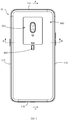
FIG. 1 is a perspective view of an image capturing device received in a mounting groove of a mobile terminal according to an embodiment of the present disclosure. -
FIG. 2 is a front view of the image capturing device received in the mounting groove of the mobile terminal shown inFIG. 1 . -
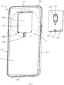
FIG. 3 is a perspective view of the image capturing device taken out of the mounting groove of the mobile terminal shown inFIG. 2 . -
FIG. 4 is an enlarged view of a portion C of the mobile terminal shown inFIG. 3 . -
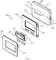
FIG. 5 is an exploded perspective view of the image capturing device of the mobile terminal shown inFIG. 3 . -
FIG. 6 is a perspective view of the image capturing device of the mobile terminal shown inFIG. 5 , omitting a cover shell. -
FIG. 7 is a cross-sectional view of the mobile terminal shown inFIG. 2 , taken along the line A-A. -
FIG. 8 is an enlarged view of a portion D of the mobile terminal shown inFIG. 7 . -
FIG. 9 is a cross-sectional view of the mobile terminal shown inFIG. 2 taking along the line B-B. -
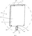
FIG. 10 is an application scenario of the image capturing device of the mobile terminal shown inFIG. 3 . -
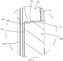
FIG. 11 is an enlarged view of a portion E of the mobile terminal shown inFIG. 7 . - In order to facilitate the understanding of the present disclosure, the present disclosure will be the comprehensively described by referring to the accompanying drawings. The drawings show preferred embodiments of the present disclosure. However, the present disclosure may be implemented in many different forms and is not limited to the embodiments described herein. On the contrary, the purpose of providing these embodiments is to enable the present disclosure to be understood more thoroughly and comprehensively.
- The "terminal device" hereinafter may refer to, but is not limited to, a device that receives and/or sends communication signals and is connected via one or more of the following connection manners:
- (1) connected via a wired line, such as public switched telephone networks (PSTN), a digital subscriber line (DSL), a digital cable, and direct cable connection;
- (2) connected via a wireless interface, such as a cellular network, a Wireless Local Area Network (WLAN), a digital TV network such as a DVB-H network, a satellite network, and an AM-FM broadcast transmitter.
- A terminal device set to communicate through a wireless interface may be referred to as the "mobile terminal." Examples of mobile terminals may include but are not limited to the following electronic devices:
- (1) a satellite phone or a cellular phone;
- (2) a personal communication system (PCS) terminal that combines a cellular radio telephone with data processing, faxing and data communication capabilities;
- (3) a radio telephone, a pager, an Internet/Intranet access, a Web browser, a notebook, a calendar, a personal digital assistant (PDA) installed with a Global Positioning System (GPS) receiver;
- (4) a conventional laptop and/or palmtop receiver;
- (5) a conventional laptop and/or palmtop radio telephone transceiver, etc.
- As shown in
FIG. 1 ,FIG. 2 , andFIG. 3 , in one embodiment, amobile terminal 10 may be a smart mobile phone. Themobile terminal 10 may include aterminal device 100, an image capturingdevice 200, a firstelastic member 300 and alock tongue 400. Theterminal device 100 may include adisplay screen 120, a first power module, and a first wireless communication module. The first power module may supply power fordisplay screen 120 and the first wireless communication module. Thedisplay screen 120 may be configured to display information and to provide an interaction interface for a user. As shown inFIG. 4 , a side of theterminal device 100 away from a display region of thedisplay screen 120 may define amounting groove 130. Further, as shown inFIG. 5 andFIG. 6 , the image capturingdevice 200 may include acover 210, acamera module 220, asecond power module 230, and a second wireless module. Thesecond power module 230 may supply power for thecamera module 220 and the second wireless communication module. Thecamera module 220 and thesecond power module 230 may be disposed inside thecover 210. Thecamera module 220 may have alight incidence face 221, and thelight incidence face 221 may be exposed from thecover 210. An ambient light may pass through thelight incidence face 221 to reach a photosensitive element of thecamera module 220. Theimage capturing device 200 may be received in the mountinggroove 130, such that thelight incidence face 221 may be exposed from the side away from the display region of thedisplay screen 120. Thecover 210 may define aslot 211. - As shown in
FIG. 4 , the firstelastic member 300 may be connected to theterminal device 100 and protrude from the mountinggroove 130. As shown inFIG. 7 andFIG. 8 , thelock tongue 400 may be slidably connected to theterminal device 100. After theimage capturing device 200 is received in the mountinggroove 130, thelock tongue 400 may slide to a first position and a second position. As shown inFIG. 8 , when thelock tongue 400 is at the first position, thelock tongue 400 may be fastened with theslot 211, theimage capturing device 200 may be locked in the mountinggroove 130, and the firstelastic member 300 may abut against theimage capturing device 200. When thelock tongue 400 is at the second position, thelock tongue 400 may be released out of theslot 211. Further as shown inFIG. 9 , the firstelastic member 300 may eject theimage capturing device 200 out of the mountinggroove 130 such that theimage capturing device 200 may be detached from the mountinggroove 130. After detaching theimage capturing device 200 from the mountinggroove 130, the second wireless communication module may be communicatively connected to the first wireless communication module, such that theimage capturing device 200 may be communicatively connected to theterminal device 100. In other embodiments, themobile terminal 10 may be a tablet. - The first wireless communication module and the second communication module may be configured for data transmission between the
terminal device 100 and theimage capturing device 200. A near field communication technology may be applied in the first wireless communication module and the second wireless communication module, and a same communication protocol may be applied in the first wireless communication module and the second wireless communication module. For example, both of the first wireless communication module and the second wireless communication module may be Bluetooth communication modules, Wireless Fidelity (Wi-Fi) communication module, infrared data association (IrDA) modules, ZigBee communication modules, ultra wideband modules, or near field communication (NFC) modules, etc. In one embodiment, theterminal device 100 may include a third wireless communication module, and the third wireless communication module may be configured to communicatively connect to an external device, such as a base station or othermobile terminals 10, such that variousmobile terminals 10 may communicate easily. - It should be understood that, in response to the
image capturing device 200 being locked in the mountinggroove 130, theimage capturing device 200 may communicatively connect to the first wireless communication module through the second wireless communication module. In this situation, thecamera module 220 may perform a function of a rear camera. The user may use theimage capturing device 200 to capture an image distantly, to record a video, and the like. After theimage capturing device 200 is detached from the mountinggroove 130, the second wireless communication module may be communicatively connected to the first wireless communication module. In this situation, the user may use theimage capturing device 200 to capture images from various angles and to capture various scenes. - In the
mobile terminal 10 as described in the above, theimage capturing device 200 may be locked in the mountinggroove 130 and detached from the mountinggroove 130. After theimage capturing device 200 being detached from the mountinggroove 130, theimage capturing device 200 may communicatively connect to the first wireless communication module of theterminal device 100 through the second wireless communication module, and the user may use theimage capturing device 200 to capture images from various angles and to capture various scenes. As shown inFIG. 10 , in one embodiment, the user may use one hand to hold theimage capturing device 200, and use the other hand to hold theterminal device 100. The user may use theimage capturing device 200 to capture images from various positions and various angles, and view the images through thedisplay screen 120 of theterminal device 100. In another example, the user may place theimage capturing device 200 at a certain location, and stand at another location and view the images captured by theimage capturing device 200 through theterminal device 100. It should be understood that, as theimage capturing device 200 is able to be detached from theterminal device 100, and is able to communicatively connect to theterminal device 100 after being detached, a front camera may not be required to be configured on a side of theterminal device 100 on which thedisplay screen 120 is disposed. Therefore, a screen-to-body ratio of theterminal device 100 may be improved. For example, by configuring theterminal device 100 in the above-mentioned structure, the screen-to-body ratio may be over 85%. It should be understood that configuration of the firstelastic member 300 and thelock tongue 400 may enable theimage capturing device 200 to be securely fixed in the mountinggroove 130, preventing theimage capturing device 200 from being released out of the mountinggroove 130 easily. When thelock tongue 400 is unlocked, the firstelastic member 300 may eject theimage capturing device 200 out of the mountinggroove 130, such that the user may take theimage capturing device 200 easily. - As shown in
FIGS. 1 to 3 , theterminal device 100 may substantially be a rectangular cube. Theterminal device 100 may include arear wall 111 and a side wall connected to an outer periphery of thedisplay screen 120. Therear wall 111 may be disposed on the side of theterminal device 100 opposite to the display region and may be connected to the side wall. The side wall may include aleft side wall 112, aright side wall 114 opposite to theleft side wall 112, atop side wall 116, and abottom side wall 118 opposite to thetop side wall 116. Theleft side wall 112 and theright side wall 114 are disposed between thetop side wall 116 and thebottom side wall 118. Thetop side wall 116 and thebottom side wall 118 are disposed between theleft side wall 112 and theright side wall 114. The mountinggroove 130 may extend through therear wall 111. The mountinggroove 130 may be defined between theleft side wall 112 and theright side wall 114, and between thetop side wall 116 and thebottom side wall 118. Further, theterminal device 100 may include amiddle board 140, disposed between thedisplay screen 120 and therear wall 111. The firstelastic member 300 may be connected to themiddle board 140. Themiddle board 140 and the side wall may be formed integrally. Alternatively, themiddle board 140 may be detachably connected to the side wall. Structural stability of the firstelastic member 300 may be improved by configuring themiddle board 140 to support the firstelastic member 300. - As shown in
FIG. 7 andFIG. 8 , a side of therear wall 111 opposite to the display region may define agroove 150 extending through therear wall 111. Thelock tongue 400 may include abody portion 410 and aslide block 420 connected to thebody portion 410. Theslide block 420 may be received in and extend through thegroove 150. Thebody portion 410 may switch between the first position and the second position by slidable engagement between theslide block 420 and thegroove 150. Further, thegroove 150 may include aslide groove 151 and areservation groove 153 communicating with theslide groove 151. Theslide block 420 may include a limitingportion 421 and aconnection portion 423, and the limitingportion 421 and theconnection portion 423 are integrally formed as an overall structure. Theconnection portion 423 may be received in and extend through thereservation groove 153, and may be detachably connected to thebody portion 410. The limitingportion 421 may be slidably received in theslide groove 151 and may be exposed from the side of therear wall 111 opposite to the display region. The user may push the limitingportion 421 to slide in theslide groove 151 to allow thebody portion 410 to switch between the first position and the second position. - Further, in one implementation, a size of a cross section of the
reservation groove 153 may be greater than that of theconnection portion 423, and the size of the cross section of thereservation groove 153 may be less than that of the limitingportion 421. In this way, theconnection portion 423 and thebody portion 410 may be engaged easily, and a position of the limitingportion 421 may be limited by thereservation groove 153, preventing the limitingportion 421 from tilting to be received in thereservation groove 153, such that reliability of movement of thelock tongue 400 may be improved. - As shown in
FIG. 8 , in one embodiment, themobile terminal 10 may include a secondelastic member 160. One end of the secondelastic member 160 may abut against thebody portion 410, and the other end of the secondelastic member 160 may abut against theterminal device 100. The secondelastic member 160 may push thebody portion 410 from the second position to the first position, such that thebody portion 410 may be received in the mountinggroove 130. In one embodiment, the secondelastic member 160 may be a spring, and may allow thelock tongue 400 to be reset easily, such that thelock tongue 400 may protrude from the mountinggroove 130 and may securely lock theimage capturing device 200 while being in the first position. In other embodiments, the secondelastic member 160 may be an elastic post, an elastic sheet, and the like. It should be understood that, the first elastic member 30 may be a spring, an elastic post, an elastic sheet, and the like, which will not be illustrated in more detail herein. It should be understood that, the secondelastic member 160 may not be an necessary element. Theimage capturing device 200 may be securely received in the mountinggroove 130 by configuring thelock tongue 400 to slide relative to therear wall 111. - Further, as shown in
FIG. 8 , in one embodiment, asecond groove wall 143 may be inclined towards a side at which thebottom side wall 118 is arranged to form a draft angle. When thelock tongue 400 moves to reach the second position to unlock theimage capturing device 200 with theterminal device 100, the draft angle may allow theimage capturing device 200 to be ejected from the mountinggroove 130 easily, such that the user may take theimage capturing device 200 out of the mountinggroove 130 easily. - As shown in
FIG. 7 andFIG. 8 , theterminal device 100 may have afirst groove wall 141 and thesecond groove wall 143 opposite tofirst groove wall 141. Compared to thesecond groove wall 143, thefirst groove wall 141 may be closer to thetop side wall 116. In the first position, thebody portion 410 may protrude from thesecond groove wall 143. Further, as shown inFIG. 11 , aprotrusion 145 may be arranged on thefirst groove wall 141. Theprotrusion 145 may protrude from the mountinggroove 130. Thecover 210 may define apositioning recess 213 corresponding to theprotrusion 145. After theimage capturing device 200 received in the mountinggroove 130, theprotrusion 145 may be fastened in thepositioning recess 213. Fastening theprotrusion 145 with thepositioning recess 213 may allow theimage capturing device 200 to be positioned inside the mountinggroove 130 easily, and allow the user to mount theimage capturing device 200 into the mountinggroove 130 securely, preventing theimage capturing device 200 from being detached from the mountinggroove 130 easily. - Further, as shown in
FIG. 5 andFIG. 6 , theimage capturing device 200 may substantially be a rectangular cube. Thecover 210 may include afront end face 215, arear end face 217 opposite to thefront end face 215, and a side end face connected to thefront end face 215 and therear end face 217. The side end face may include aleft end face 212, aright end face 214 opposite to theleft end face 212, atop end face 216, and abottom end face 218 opposite to thetop end face 216. Theleft end face 212 and theright end face 214 may be disposed between thetop end face 216 and thebottom end face 218. Thetop end face 216 and thebottom end face 218 may be disposed between theleft end face 212 and theright end face 214. Thelight incidence face 221 may be exposed from thefront end face 215. Theslot 211 may be defined in a side at which thebottom end face 218 is disposed. In the embodiment where theimage capturing device 200 defines thepositioning recess 213, thepositioning recess 213 may be defined in the side at which thetop end face 216 is disposed. When theimage capturing device 200 is received in the mountinggroove 130, thefront end face 215 may flush with an outer surface of therear wall 111. After theimage capturing device 200 having the above-mentioned structure is received in the mountinggroove 130, an appearance of themobile terminal 10 may be highly maintained as an integral. In one embodiment, thelight incidence face 221 may protrude form thefront end face 215. In this way, a position of theimage capturing device 200 at which thelight incidence face 221 is disposed may be manufactured to be relatively thick, and other positions of theimage capturing device 200 may be manufactured to be relatively thin. In this way, theimage capturing device 200 may be light and thin, and themobile terminal 10 may be light and thin. - In one embodiment, the
image capturing device 200 may include a module contact, and theterminal device 100 may include a device contact. When the image capturing device is received in the mountinggroove 130, the module contact may be in contact with and connected to the device contact, such that theterminal device 100 may charge theimage capturing device 200. In this way, theterminal device 100 may easily charge theimage capturing device 200, and theimage capturing device 200 may remain sufficient power to be used by the user easily. It should be understood that each of the module contact or the device contact may be a metal contact, and may have various structural forms. For example, theimage capturing device 200 may define a hole, and the metal contact may be received in the hole, serving as the module contact. Theterminal device 100 may be arranged with a protruded metal contact, serving as the device contact. Theterminal device 100 charging theterminal device 100 may be achieved by engaging the module contact with the device contact. Further, in one implementation, theprotrusion 145 may have the metal contact structure, serving as the device contact, and the metal contact may be received in thepositioning recess 213 to serve as the module contact. - As shown in
FIG. 5 andFIG. 6 , theimage capturing device 200 may include a modulemain board 240 in thecover 210. Thesecond power module 230 may be stacked on the modulemain board 240 and supply power for the modulemain board 240. The modulemain board 240 may be communicatively connected to thecamera module 220 and the second wireless communication module. The modulemain board 240 may include a circuit board and a plurality of electronic elements connected to the circuit board. The modulemain board 240 may process image information collected by thecamera module 220, and send the image information to theterminal device 100 via the second wireless communication module. The modulemain board 240 may define a first throughhole 241 to allow the modulemain board 240 to be substantially ring-shaped. Thecamera module 220 may include alens tube 223, and thelens tube 223 may be received in and extend through the first throughhole 241. In this way, thelens tube 223 may not stack above the modulemain board 240, and therefore, internal elements of theimage capturing device 200 may be arranged compactly, and an overall thickness of theimage capturing device 200 may be reduced. - Further, the
second power module 230 may define a second throughhole 231 to allow thesecond power module 230 to be substantially ring-shaped. The second throughhole 231 may communicate with the first throughhole 241. Thelens tube 223 may extend through the first throughhole 241 and the second throughhole 231. In this way, thelens tube 223 may not stack above thesecond power module 230. Therefore, the internal elements of theimage capturing device 200 may be arranged compactly, and the overall thickness of theimage capturing device 200 may be reduced. It should be understood that each of the first power module and thesecond power module 230 may include a battery able to repeatedly charge and discharge, such as a lithium battery. In other embodiments, each of the first power module and thesecond power module 230 may be a fuel battery or other types of batteries. Thesecond power module 230 may be connected to the modulemain board 240 through a power flexible printed circuit board (FPC), such that thesecond power module 230 may supply power for the modulemain board 240, which will not be described in detail herein. - Various technical features of the above-mentioned embodiments may be combined arbitrarily. In order to provide a concise description, all possible combinations of the various technical features in the above-mentioned embodiments are not described. However, as long as there is no contradiction in the combination of these technical features, all the combinations should be included in the scope of the present disclosure.
- The above-mentioned embodiments only show several implementations of the present disclosure, and the several implementations are described in specific details, but it should not be understood as a limitation of the scope of the present disclosure. It should be noted that for those ordinary skilled in the art, without departing from the concept of the present disclosure, various modifications and improvements may be made and should fall within the scope of the present disclosure. Therefore, the scope of the present disclosure shall be subject to the appended claims.
Claims (21)
- A mobile terminal, comprising:a terminal device, comprising a display screen, a first power module, and a first wireless communication module, wherein the first power module is configured to supply power for the display screen and the first wireless communication module, a side of the terminal device opposite to a display region of the display screen defines a mounting groove;an image capturing device, comprising a cover, a camera module, a second power module, and a second wireless communication module, wherein the second power module is configured to supply power for the camera module and the second wireless communication module, the camera module and the second power module are disposed inside the cover, the camera module has a light incidence face exposed from the cover, the image capturing device is capable of being received in the mounting groove to allow the light incidence face to be exposed from the side opposite to the display region, the cover defines a slot;a first elastic member, connected to the terminal device and protruding from the mounting groove; anda lock tongue, slidably connected to the terminal device, wherein after the image capturing device is received in the mounting groove,the lock tongue is capable of sliding to reach a first position and a second position;the lock tongue is fastened with the slot, the image capturing device is locked in the mounting groove, and the first elastic member abuts against the image capturing device, when the lock tongue is at the first position;the lock tongue is released from the slot, and the first elastic member is configured to eject the image capturing device out of the mounting groove to allow the image capturing device to be detached from the mounting groove, when the lock tongue is at the second position; andafter the image capturing device is detached from the mounting, groove, the second wireless communication module is communicatively connected to the first wireless communication module.
- The mobile terminal as claimed in claim 1, wherein the terminal device comprises a rear wall and a side wall connected to an outer periphery of the display screen;
the rear wall is disposed on the side opposite to the display region and is connected to the side wall;
the side wall comprises a left side wall, a right side wall opposite to the left side wall, a top side wall, and a bottom side wall opposite to the top side wall;
the left side wall and the right side wall are disposed between the top side wall and the bottom side wall;
the top side wall and the bottom side wall are disposed between the left side wall and the right side wall;
the mounting groove extends through the rear wall;
the mounting groove is defined between the left side wall and the right side wall, and is defined between the top side wall and the bottom side wall. - The mobile terminal as claimed in claim 2, wherein a side of the rear wall opposite to the display region defines a groove extending through the rear wall;
the lock tongue comprises a body portion and a slide block connected to the body portion;
the slide block extends through the groove; and
the body portion is switched between the first position and the second position by sliding engagement between the slide block and the groove. - The mobile terminal as claimed in claim 3, wherein the groove comprises a slide groove and a reservation groove communicating with the slide groove;
the slide block comprises a limiting portion and a connection portion, the limiting portion and the connection portion are connected with each other to be an integral structure;
the connection portion is received in and extends through the reservation groove and is detachably connected to the body portion;
the limiting portion is slidably received in the slide groove and is exposed from the side of the rear wall opposite to the display region. - The mobile terminal as claimed in claim 4, wherein a size of a cross section of the reservation groove is greater than that of the connection portion, and the size of the cross section of the reservation groove is less than that of the limiting portion.
- The mobile terminal as claimed in claim 4, further comprising a second elastic member, wherein one end of the second elastic member abuts against the body portion, the other end of the second elastic member abuts against the terminal device; and
the second elastic member is configured to push the body portion from the second position to the first position to allow the body portion to be received in the mounting groove. - The mobile terminal as claimed in claim 3, wherein the terminal device has a first groove wall and a second groove wall opposite to the first groove wall;
compared to the second groove wall, the first groove wall is closer to the top side wall;
the body portion protrudes from the second groove wall at the first position;
the first groove wall is arranged with a protrusion, the protrusion protrudes from the mounting groove;
the cover defines a positioning recess; and
after the image capturing device is received in the mounting groove, the protrusion is fastened into the positioning recess. - The mobile terminal as claimed in claim 7, wherein the second groove wall is inclined towards a side at which the bottom side wall is disposed to serve as a draft angle.
- The mobile terminal as claimed in claim 2, wherein the cover comprises a front end face, a rear end face opposite to the front end face, and a side end face connected between the front end face and the rear end face;
the side end face comprises a left end face, a right end face opposite to the left end face, a top end face, and a bottom end face opposite to the top end face;
the left end face and the right end face are disposed between the top end face and the bottom end face;
the top end face and the bottom end face are disposed between the left end face and the right end face;
the light incidence face is exposed from the front end face;
when the image capturing device is received in the mounting groove, the front end face flushes with an outer surface of the rear wall. - The mobile terminal as claimed in claim 1, wherein the image capturing device comprises a module contact, the terminal device comprises a device contact;
when the image capturing device is received in the mounting groove, the module contact is in contact with and connected to the device contact to allow the terminal device to charge the image capturing device. - The mobile terminal as claimed in claim 1, wherein the image capturing device comprises a module main board disposed inside the cover;
the second power module is stacked on the module main board and is configured to supply power for the module main board;
the module main board is communicatively connected to the camera module and the second wireless communication module;
the module main board defines a first through hole, the camera module comprises a lens tube, and the lens tube extends through the first through hole. - The mobile terminal as claimed in claim 11, wherein the second power module defines a second through hole, the second through hole communicates with the first through hole, and the lens tube extends through the second through hole.
- The mobile terminal as claimed in claim 1, wherein both of the first wireless communication module and the second wireless communication module are Bluetooth communication modules, or WiFi communication modules, or ZigBee communication modules, or NFC communication modules.
- A mobile terminal, comprising:a terminal device, comprising a display screen and a first wireless communication module, wherein the display screen has a display region, and a side of the terminal device opposite to the display region defines a mounting groove;an image capturing device, comprising a cover, a camera module, and a second wireless communication module, whereinthe cover defines a slot, the camera module is disposed inside the cover;the camera module has a light incidence face, the image capturing device is capable of being received in the mounting groove to allow the light incidence face to be exposed from the side opposite to the display region;the image capturing device is communicatively connected to the first wireless communication module through the second wireless communication module;a first elastic member, connected to the terminal device and protruding from the mounting groove; anda lock tongue, slidably connected to the terminal device, whereinthe lock tongue is capable of sliding to reach a first position and a second position;after the image capturing device is received in the mounting groove, the lock tongue is fastened with the slot at the first position to lock the image capturing device in the mounting groove, and the first elastic member abuts against the image capturing device;the lock tongue is released from the slot at the second position, and the first elastic member is configured to eject the image capturing device out of the mounting groove.
- The mobile terminal as claimed in claim 14, wherein the terminal device comprises a rear wall and a side wall connected to an outer periphery of the display screen;
the rear wall is disposed on the side opposite to the display region and is connected to the side wall;
the mounting groove extends through the rear wall. - The mobile terminal as claimed in claim 15, wherein the cover comprises a front end face, a rear end face opposite to the front end face, and a side end face connected between the front end face and the rear end face;
the side end face comprises a left end face, a right end face opposite to the left end face, a top end face, and a bottom end face opposite to the top end face;
the left end face and the right end face are disposed between the top end face and the bottom end face;
the top end face and the bottom end face are disposed between the left end face and the right end face;
the light incidence face is exposed from the front end face;
when the image capturing device is received in the mounting groove, the front end face flushes with an outer surface of the rear wall. - The mobile terminal as claimed in claim 15 or claim 16, wherein a side of the rear wall opposite to the display region defines a groove extending through the rear wall;
the lock tongue comprises a body portion and a slide block connected to the body portion;
the slide block extends through the groove; and
the body portion is switched between the first position and the second position by sliding engagement between the slide block and the groove. - The mobile terminal as claimed in claim 17, wherein the groove comprises a slide groove and a reservation groove;
the slide block comprises a limiting portion and a connection portion, the limiting portion and the connection portion are connected with each other to serve as an integral structure;
the connection portion is received in and extends through the reservation groove and is detachably connected to the body portion;
the limiting portion is slidably received in the slide groove and is exposed from the side of the rear wall opposite to the display region. - The mobile terminal as claimed in claim 18, wherein a size of a cross section of the reservation groove is greater than that of the connection portion, and the size of the cross section of the reservation groove is less than that of the limiting portion.
- The mobile terminal according to claim 18, further comprising a second elastic member, wherein one end of the second elastic member abuts against the body portion, the other end of the second elastic member abuts against the terminal device; and
the second elastic member is configured to push the body portion from the second position to the first position to allow the body portion to be received in the mounting groove. - The mobile terminal according to claim 14, wherein the image capturing device comprises a module contact, the terminal device comprises a device contact;
when the image capturing device is received in the mounting groove, the module contact is in contact with and connected to the device contact to allow the terminal device to charge the image capturing device.
Applications Claiming Priority (2)
| Application Number | Priority Date | Filing Date | Title |
|---|---|---|---|
| CN201821460525.3U CN209608691U (en) | 2018-09-06 | 2018-09-06 | Mobile terminal |
| PCT/CN2019/095737 WO2020048225A1 (en) | 2018-09-06 | 2019-07-12 | Mobile terminal |
Publications (3)
| Publication Number | Publication Date |
|---|---|
| EP3836519A1 true EP3836519A1 (en) | 2021-06-16 |
| EP3836519A4 EP3836519A4 (en) | 2021-10-20 |
| EP3836519B1 EP3836519B1 (en) | 2023-04-19 |
Family
ID=68393386
Family Applications (1)
| Application Number | Title | Priority Date | Filing Date |
|---|---|---|---|
| EP19858234.8A Active EP3836519B1 (en) | 2018-09-06 | 2019-07-12 | Mobile terminal |
Country Status (4)
| Country | Link |
|---|---|
| US (1) | US20210195005A1 (en) |
| EP (1) | EP3836519B1 (en) |
| CN (1) | CN209608691U (en) |
| WO (1) | WO2020048225A1 (en) |
Cited By (1)
| Publication number | Priority date | Publication date | Assignee | Title |
|---|---|---|---|---|
| CN114899648A (en) * | 2022-04-20 | 2022-08-12 | 荣耀终端有限公司 | Electronic device |
Families Citing this family (2)
| Publication number | Priority date | Publication date | Assignee | Title |
|---|---|---|---|---|
| CN111140929B (en) * | 2020-01-19 | 2025-02-07 | 广东美的制冷设备有限公司 | Air dispersion components and air conditioners |
| US11303790B1 (en) * | 2020-12-12 | 2022-04-12 | John G. Posa | Electronic binocular modules adapted for attachment to smartphones and cases therefor |
Family Cites Families (6)
| Publication number | Priority date | Publication date | Assignee | Title |
|---|---|---|---|---|
| KR20030073271A (en) * | 2002-03-09 | 2003-09-19 | 주식회사 엘지이아이 | Hand-held terminal including assembly and disassembly function of module |
| KR20150064955A (en) * | 2013-12-04 | 2015-06-12 | 엘지전자 주식회사 | Mobile terminal |
| KR101727512B1 (en) * | 2014-11-04 | 2017-04-17 | 엘지전자 주식회사 | Mobile terminal |
| CN104363316B (en) * | 2014-11-06 | 2018-03-27 | 广东欧珀移动通信有限公司 | Mobile terminal |
| US10795240B2 (en) * | 2016-11-18 | 2020-10-06 | Moment Inc | Protective case for a mobile device |
| CN206413044U (en) * | 2016-12-25 | 2017-08-15 | 北京沃凡思智选家居科技有限公司 | mobile phone with camera unit |
-
2018
- 2018-09-06 CN CN201821460525.3U patent/CN209608691U/en not_active Expired - Fee Related
-
2019
- 2019-07-12 EP EP19858234.8A patent/EP3836519B1/en active Active
- 2019-07-12 WO PCT/CN2019/095737 patent/WO2020048225A1/en not_active Ceased
-
2021
- 2021-03-04 US US17/192,054 patent/US20210195005A1/en not_active Abandoned
Cited By (1)
| Publication number | Priority date | Publication date | Assignee | Title |
|---|---|---|---|---|
| CN114899648A (en) * | 2022-04-20 | 2022-08-12 | 荣耀终端有限公司 | Electronic device |
Also Published As
| Publication number | Publication date |
|---|---|
| CN209608691U (en) | 2019-11-08 |
| EP3836519A4 (en) | 2021-10-20 |
| WO2020048225A1 (en) | 2020-03-12 |
| US20210195005A1 (en) | 2021-06-24 |
| EP3836519B1 (en) | 2023-04-19 |
Similar Documents
| Publication | Publication Date | Title |
|---|---|---|
| CN110557470B (en) | Mobile Terminal | |
| US20210195005A1 (en) | Mobile Terminal and Photographing System | |
| US11265451B2 (en) | Camera module and mobile terminal | |
| WO2019228380A1 (en) | Camera module and mobile terminal | |
| US20210195006A1 (en) | Mobile terminal | |
| WO2019228324A1 (en) | Mobile terminal | |
| CN110557468B (en) | Mobile terminal | |
| CN208987022U (en) | Mobile terminal | |
| CN209390166U (en) | Image acquisition equipment and electronic devices | |
| CN111433685B (en) | Watch modules, watches, electronic equipment, electronic devices and mobile terminals | |
| CN110557472B (en) | Mobile Terminal | |
| CN110557467B (en) | Image acquisition equipment and electronic devices | |
| US10681193B2 (en) | Mobile terminal | |
| CN208890847U (en) | mobile terminal | |
| CN110557469B (en) | Mobile Terminal | |
| CN110138913A (en) | Mobile terminal | |
| CN210041886U (en) | electronic device | |
| CN209134461U (en) | Mobile terminal | |
| CN209134462U (en) | Mobile terminal | |
| CN110557524B (en) | Image acquisition equipment and electronic devices | |
| WO2019228383A1 (en) | Image acquisition apparatus and electronic device | |
| CN209572030U (en) | mobile terminal | |
| CN111512615B (en) | electronic device | |
| CN209497511U (en) | Mobile terminal | |
| WO2019228322A1 (en) | Mobile terminal |
Legal Events
| Date | Code | Title | Description |
|---|---|---|---|
| STAA | Information on the status of an ep patent application or granted ep patent |
Free format text: STATUS: THE INTERNATIONAL PUBLICATION HAS BEEN MADE |
|
| PUAI | Public reference made under article 153(3) epc to a published international application that has entered the european phase |
Free format text: ORIGINAL CODE: 0009012 |
|
| STAA | Information on the status of an ep patent application or granted ep patent |
Free format text: STATUS: REQUEST FOR EXAMINATION WAS MADE |
|
| 17P | Request for examination filed |
Effective date: 20210312 |
|
| AK | Designated contracting states |
Kind code of ref document: A1 Designated state(s): AL AT BE BG CH CY CZ DE DK EE ES FI FR GB GR HR HU IE IS IT LI LT LU LV MC MK MT NL NO PL PT RO RS SE SI SK SM TR |
|
| A4 | Supplementary search report drawn up and despatched |
Effective date: 20210916 |
|
| RIC1 | Information provided on ipc code assigned before grant |
Ipc: H04M 1/72412 20210101ALN20210910BHEP Ipc: H04N 5/225 20060101ALI20210910BHEP Ipc: H04M 1/02 20060101AFI20210910BHEP |
|
| DAV | Request for validation of the european patent (deleted) | ||
| DAX | Request for extension of the european patent (deleted) | ||
| GRAP | Despatch of communication of intention to grant a patent |
Free format text: ORIGINAL CODE: EPIDOSNIGR1 |
|
| STAA | Information on the status of an ep patent application or granted ep patent |
Free format text: STATUS: GRANT OF PATENT IS INTENDED |
|
| RIC1 | Information provided on ipc code assigned before grant |
Ipc: H04M 1/72412 20210101ALN20221221BHEP Ipc: H04N 5/225 20060101ALI20221221BHEP Ipc: H04M 1/02 20060101AFI20221221BHEP |
|
| INTG | Intention to grant announced |
Effective date: 20230120 |
|
| RIC1 | Information provided on ipc code assigned before grant |
Ipc: H04M 1/72412 20210101ALN20230109BHEP Ipc: H04N 23/57 20230101ALI20230109BHEP Ipc: H04M 1/02 19680901AFI20230109BHEP |
|
| GRAS | Grant fee paid |
Free format text: ORIGINAL CODE: EPIDOSNIGR3 |
|
| GRAA | (expected) grant |
Free format text: ORIGINAL CODE: 0009210 |
|
| STAA | Information on the status of an ep patent application or granted ep patent |
Free format text: STATUS: THE PATENT HAS BEEN GRANTED |
|
| AK | Designated contracting states |
Kind code of ref document: B1 Designated state(s): AL AT BE BG CH CY CZ DE DK EE ES FI FR GB GR HR HU IE IS IT LI LT LU LV MC MK MT NL NO PL PT RO RS SE SI SK SM TR |
|
| REG | Reference to a national code |
Ref country code: GB Ref legal event code: FG4D |
|
| REG | Reference to a national code |
Ref country code: DE Ref legal event code: R096 Ref document number: 602019027879 Country of ref document: DE |
|
| REG | Reference to a national code |
Ref country code: CH Ref legal event code: EP |
|
| REG | Reference to a national code |
Ref country code: IE Ref legal event code: FG4D |
|
| REG | Reference to a national code |
Ref country code: AT Ref legal event code: REF Ref document number: 1562056 Country of ref document: AT Kind code of ref document: T Effective date: 20230515 |
|
| P01 | Opt-out of the competence of the unified patent court (upc) registered |
Effective date: 20230525 |
|
| REG | Reference to a national code |
Ref country code: LT Ref legal event code: MG9D |
|
| REG | Reference to a national code |
Ref country code: NL Ref legal event code: MP Effective date: 20230419 |
|
| REG | Reference to a national code |
Ref country code: AT Ref legal event code: MK05 Ref document number: 1562056 Country of ref document: AT Kind code of ref document: T Effective date: 20230419 |
|
| PG25 | Lapsed in a contracting state [announced via postgrant information from national office to epo] |
Ref country code: NL Free format text: LAPSE BECAUSE OF FAILURE TO SUBMIT A TRANSLATION OF THE DESCRIPTION OR TO PAY THE FEE WITHIN THE PRESCRIBED TIME-LIMIT Effective date: 20230419 |
|
| PG25 | Lapsed in a contracting state [announced via postgrant information from national office to epo] |
Ref country code: SE Free format text: LAPSE BECAUSE OF FAILURE TO SUBMIT A TRANSLATION OF THE DESCRIPTION OR TO PAY THE FEE WITHIN THE PRESCRIBED TIME-LIMIT Effective date: 20230419 Ref country code: PT Free format text: LAPSE BECAUSE OF FAILURE TO SUBMIT A TRANSLATION OF THE DESCRIPTION OR TO PAY THE FEE WITHIN THE PRESCRIBED TIME-LIMIT Effective date: 20230821 Ref country code: NO Free format text: LAPSE BECAUSE OF FAILURE TO SUBMIT A TRANSLATION OF THE DESCRIPTION OR TO PAY THE FEE WITHIN THE PRESCRIBED TIME-LIMIT Effective date: 20230719 Ref country code: ES Free format text: LAPSE BECAUSE OF FAILURE TO SUBMIT A TRANSLATION OF THE DESCRIPTION OR TO PAY THE FEE WITHIN THE PRESCRIBED TIME-LIMIT Effective date: 20230419 Ref country code: AT Free format text: LAPSE BECAUSE OF FAILURE TO SUBMIT A TRANSLATION OF THE DESCRIPTION OR TO PAY THE FEE WITHIN THE PRESCRIBED TIME-LIMIT Effective date: 20230419 |
|
| PG25 | Lapsed in a contracting state [announced via postgrant information from national office to epo] |
Ref country code: RS Free format text: LAPSE BECAUSE OF FAILURE TO SUBMIT A TRANSLATION OF THE DESCRIPTION OR TO PAY THE FEE WITHIN THE PRESCRIBED TIME-LIMIT Effective date: 20230419 Ref country code: PL Free format text: LAPSE BECAUSE OF FAILURE TO SUBMIT A TRANSLATION OF THE DESCRIPTION OR TO PAY THE FEE WITHIN THE PRESCRIBED TIME-LIMIT Effective date: 20230419 Ref country code: LV Free format text: LAPSE BECAUSE OF FAILURE TO SUBMIT A TRANSLATION OF THE DESCRIPTION OR TO PAY THE FEE WITHIN THE PRESCRIBED TIME-LIMIT Effective date: 20230419 Ref country code: LT Free format text: LAPSE BECAUSE OF FAILURE TO SUBMIT A TRANSLATION OF THE DESCRIPTION OR TO PAY THE FEE WITHIN THE PRESCRIBED TIME-LIMIT Effective date: 20230419 Ref country code: IS Free format text: LAPSE BECAUSE OF FAILURE TO SUBMIT A TRANSLATION OF THE DESCRIPTION OR TO PAY THE FEE WITHIN THE PRESCRIBED TIME-LIMIT Effective date: 20230819 Ref country code: HR Free format text: LAPSE BECAUSE OF FAILURE TO SUBMIT A TRANSLATION OF THE DESCRIPTION OR TO PAY THE FEE WITHIN THE PRESCRIBED TIME-LIMIT Effective date: 20230419 Ref country code: GR Free format text: LAPSE BECAUSE OF FAILURE TO SUBMIT A TRANSLATION OF THE DESCRIPTION OR TO PAY THE FEE WITHIN THE PRESCRIBED TIME-LIMIT Effective date: 20230720 Ref country code: AL Free format text: LAPSE BECAUSE OF FAILURE TO SUBMIT A TRANSLATION OF THE DESCRIPTION OR TO PAY THE FEE WITHIN THE PRESCRIBED TIME-LIMIT Effective date: 20230419 |
|
| PG25 | Lapsed in a contracting state [announced via postgrant information from national office to epo] |
Ref country code: FI Free format text: LAPSE BECAUSE OF FAILURE TO SUBMIT A TRANSLATION OF THE DESCRIPTION OR TO PAY THE FEE WITHIN THE PRESCRIBED TIME-LIMIT Effective date: 20230419 |
|
| PG25 | Lapsed in a contracting state [announced via postgrant information from national office to epo] |
Ref country code: SK Free format text: LAPSE BECAUSE OF FAILURE TO SUBMIT A TRANSLATION OF THE DESCRIPTION OR TO PAY THE FEE WITHIN THE PRESCRIBED TIME-LIMIT Effective date: 20230419 |
|
| REG | Reference to a national code |
Ref country code: DE Ref legal event code: R097 Ref document number: 602019027879 Country of ref document: DE |
|
| PG25 | Lapsed in a contracting state [announced via postgrant information from national office to epo] |
Ref country code: SM Free format text: LAPSE BECAUSE OF FAILURE TO SUBMIT A TRANSLATION OF THE DESCRIPTION OR TO PAY THE FEE WITHIN THE PRESCRIBED TIME-LIMIT Effective date: 20230419 Ref country code: SK Free format text: LAPSE BECAUSE OF FAILURE TO SUBMIT A TRANSLATION OF THE DESCRIPTION OR TO PAY THE FEE WITHIN THE PRESCRIBED TIME-LIMIT Effective date: 20230419 Ref country code: RO Free format text: LAPSE BECAUSE OF FAILURE TO SUBMIT A TRANSLATION OF THE DESCRIPTION OR TO PAY THE FEE WITHIN THE PRESCRIBED TIME-LIMIT Effective date: 20230419 Ref country code: EE Free format text: LAPSE BECAUSE OF FAILURE TO SUBMIT A TRANSLATION OF THE DESCRIPTION OR TO PAY THE FEE WITHIN THE PRESCRIBED TIME-LIMIT Effective date: 20230419 Ref country code: DK Free format text: LAPSE BECAUSE OF FAILURE TO SUBMIT A TRANSLATION OF THE DESCRIPTION OR TO PAY THE FEE WITHIN THE PRESCRIBED TIME-LIMIT Effective date: 20230419 Ref country code: CZ Free format text: LAPSE BECAUSE OF FAILURE TO SUBMIT A TRANSLATION OF THE DESCRIPTION OR TO PAY THE FEE WITHIN THE PRESCRIBED TIME-LIMIT Effective date: 20230419 |
|
| REG | Reference to a national code |
Ref country code: DE Ref legal event code: R119 Ref document number: 602019027879 Country of ref document: DE |
|
| PLBE | No opposition filed within time limit |
Free format text: ORIGINAL CODE: 0009261 |
|
| STAA | Information on the status of an ep patent application or granted ep patent |
Free format text: STATUS: NO OPPOSITION FILED WITHIN TIME LIMIT |
|
| PG25 | Lapsed in a contracting state [announced via postgrant information from national office to epo] |
Ref country code: MC Free format text: LAPSE BECAUSE OF FAILURE TO SUBMIT A TRANSLATION OF THE DESCRIPTION OR TO PAY THE FEE WITHIN THE PRESCRIBED TIME-LIMIT Effective date: 20230419 |
|
| PG25 | Lapsed in a contracting state [announced via postgrant information from national office to epo] |
Ref country code: MC Free format text: LAPSE BECAUSE OF FAILURE TO SUBMIT A TRANSLATION OF THE DESCRIPTION OR TO PAY THE FEE WITHIN THE PRESCRIBED TIME-LIMIT Effective date: 20230419 |
|
| REG | Reference to a national code |
Ref country code: CH Ref legal event code: PL |
|
| REG | Reference to a national code |
Ref country code: BE Ref legal event code: MM Effective date: 20230731 |
|
| PG25 | Lapsed in a contracting state [announced via postgrant information from national office to epo] |
Ref country code: LU Free format text: LAPSE BECAUSE OF NON-PAYMENT OF DUE FEES Effective date: 20230712 |
|
| 26N | No opposition filed |
Effective date: 20240122 |
|
| GBPC | Gb: european patent ceased through non-payment of renewal fee |
Effective date: 20230719 |
|
| PG25 | Lapsed in a contracting state [announced via postgrant information from national office to epo] |
Ref country code: LU Free format text: LAPSE BECAUSE OF NON-PAYMENT OF DUE FEES Effective date: 20230712 |
|
| REG | Reference to a national code |
Ref country code: IE Ref legal event code: MM4A |
|
| PG25 | Lapsed in a contracting state [announced via postgrant information from national office to epo] |
Ref country code: DE Free format text: LAPSE BECAUSE OF NON-PAYMENT OF DUE FEES Effective date: 20240201 Ref country code: GB Free format text: LAPSE BECAUSE OF NON-PAYMENT OF DUE FEES Effective date: 20230719 Ref country code: CH Free format text: LAPSE BECAUSE OF NON-PAYMENT OF DUE FEES Effective date: 20230731 |
|
| PG25 | Lapsed in a contracting state [announced via postgrant information from national office to epo] |
Ref country code: SI Free format text: LAPSE BECAUSE OF FAILURE TO SUBMIT A TRANSLATION OF THE DESCRIPTION OR TO PAY THE FEE WITHIN THE PRESCRIBED TIME-LIMIT Effective date: 20230419 |
|
| PG25 | Lapsed in a contracting state [announced via postgrant information from national office to epo] |
Ref country code: SI Free format text: LAPSE BECAUSE OF FAILURE TO SUBMIT A TRANSLATION OF THE DESCRIPTION OR TO PAY THE FEE WITHIN THE PRESCRIBED TIME-LIMIT Effective date: 20230419 Ref country code: IT Free format text: LAPSE BECAUSE OF FAILURE TO SUBMIT A TRANSLATION OF THE DESCRIPTION OR TO PAY THE FEE WITHIN THE PRESCRIBED TIME-LIMIT Effective date: 20230419 Ref country code: FR Free format text: LAPSE BECAUSE OF NON-PAYMENT OF DUE FEES Effective date: 20230731 Ref country code: BE Free format text: LAPSE BECAUSE OF NON-PAYMENT OF DUE FEES Effective date: 20230731 |
|
| PG25 | Lapsed in a contracting state [announced via postgrant information from national office to epo] |
Ref country code: IE Free format text: LAPSE BECAUSE OF NON-PAYMENT OF DUE FEES Effective date: 20230712 |
|
| PG25 | Lapsed in a contracting state [announced via postgrant information from national office to epo] |
Ref country code: IE Free format text: LAPSE BECAUSE OF NON-PAYMENT OF DUE FEES Effective date: 20230712 |
|
| PG25 | Lapsed in a contracting state [announced via postgrant information from national office to epo] |
Ref country code: BG Free format text: LAPSE BECAUSE OF FAILURE TO SUBMIT A TRANSLATION OF THE DESCRIPTION OR TO PAY THE FEE WITHIN THE PRESCRIBED TIME-LIMIT Effective date: 20230419 |
|
| PG25 | Lapsed in a contracting state [announced via postgrant information from national office to epo] |
Ref country code: BG Free format text: LAPSE BECAUSE OF FAILURE TO SUBMIT A TRANSLATION OF THE DESCRIPTION OR TO PAY THE FEE WITHIN THE PRESCRIBED TIME-LIMIT Effective date: 20230419 |
|
| PG25 | Lapsed in a contracting state [announced via postgrant information from national office to epo] |
Ref country code: CY Free format text: LAPSE BECAUSE OF FAILURE TO SUBMIT A TRANSLATION OF THE DESCRIPTION OR TO PAY THE FEE WITHIN THE PRESCRIBED TIME-LIMIT; INVALID AB INITIO Effective date: 20190712 |
|
| PG25 | Lapsed in a contracting state [announced via postgrant information from national office to epo] |
Ref country code: HU Free format text: LAPSE BECAUSE OF FAILURE TO SUBMIT A TRANSLATION OF THE DESCRIPTION OR TO PAY THE FEE WITHIN THE PRESCRIBED TIME-LIMIT; INVALID AB INITIO Effective date: 20190712 |
|
| PG25 | Lapsed in a contracting state [announced via postgrant information from national office to epo] |
Ref country code: TR Free format text: LAPSE BECAUSE OF FAILURE TO SUBMIT A TRANSLATION OF THE DESCRIPTION OR TO PAY THE FEE WITHIN THE PRESCRIBED TIME-LIMIT Effective date: 20230419 |