EP3836468A1 - Procédé d'indication et de détermination de ressources de canal de liaison montante, et base station, terminal et support - Google Patents
Procédé d'indication et de détermination de ressources de canal de liaison montante, et base station, terminal et support Download PDFInfo
- Publication number
- EP3836468A1 EP3836468A1 EP19848365.3A EP19848365A EP3836468A1 EP 3836468 A1 EP3836468 A1 EP 3836468A1 EP 19848365 A EP19848365 A EP 19848365A EP 3836468 A1 EP3836468 A1 EP 3836468A1
- Authority
- EP
- European Patent Office
- Prior art keywords
- subbands
- uplink data
- harq
- data transmission
- downlink control
- Prior art date
- Legal status (The legal status is an assumption and is not a legal conclusion. Google has not performed a legal analysis and makes no representation as to the accuracy of the status listed.)
- Pending
Links
- 238000000034 method Methods 0.000 title claims abstract description 66
- 230000011664 signaling Effects 0.000 claims abstract description 27
- 230000005540 biological transmission Effects 0.000 claims description 140
- 238000001514 detection method Methods 0.000 claims description 73
- 230000008569 process Effects 0.000 claims description 11
- 238000010586 diagram Methods 0.000 description 16
- 238000001228 spectrum Methods 0.000 description 12
- 238000013468 resource allocation Methods 0.000 description 4
- 230000008901 benefit Effects 0.000 description 3
- 238000005516 engineering process Methods 0.000 description 2
- 230000002776 aggregation Effects 0.000 description 1
- 238000004220 aggregation Methods 0.000 description 1
- 238000004891 communication Methods 0.000 description 1
- 230000007774 longterm Effects 0.000 description 1
- 230000007246 mechanism Effects 0.000 description 1
- 230000003287 optical effect Effects 0.000 description 1
- 230000008520 organization Effects 0.000 description 1
Images


Classifications
-
- H—ELECTRICITY
- H04—ELECTRIC COMMUNICATION TECHNIQUE
- H04L—TRANSMISSION OF DIGITAL INFORMATION, e.g. TELEGRAPHIC COMMUNICATION
- H04L1/00—Arrangements for detecting or preventing errors in the information received
- H04L1/12—Arrangements for detecting or preventing errors in the information received by using return channel
- H04L1/16—Arrangements for detecting or preventing errors in the information received by using return channel in which the return channel carries supervisory signals, e.g. repetition request signals
- H04L1/18—Automatic repetition systems, e.g. Van Duuren systems
- H04L1/1867—Arrangements specially adapted for the transmitter end
- H04L1/1887—Scheduling and prioritising arrangements
-
- H—ELECTRICITY
- H04—ELECTRIC COMMUNICATION TECHNIQUE
- H04L—TRANSMISSION OF DIGITAL INFORMATION, e.g. TELEGRAPHIC COMMUNICATION
- H04L1/00—Arrangements for detecting or preventing errors in the information received
- H04L1/12—Arrangements for detecting or preventing errors in the information received by using return channel
- H04L1/16—Arrangements for detecting or preventing errors in the information received by using return channel in which the return channel carries supervisory signals, e.g. repetition request signals
- H04L1/1607—Details of the supervisory signal
- H04L1/1671—Details of the supervisory signal the supervisory signal being transmitted together with control information
-
- H—ELECTRICITY
- H04—ELECTRIC COMMUNICATION TECHNIQUE
- H04L—TRANSMISSION OF DIGITAL INFORMATION, e.g. TELEGRAPHIC COMMUNICATION
- H04L1/00—Arrangements for detecting or preventing errors in the information received
- H04L1/12—Arrangements for detecting or preventing errors in the information received by using return channel
- H04L1/16—Arrangements for detecting or preventing errors in the information received by using return channel in which the return channel carries supervisory signals, e.g. repetition request signals
- H04L1/18—Automatic repetition systems, e.g. Van Duuren systems
- H04L1/1812—Hybrid protocols; Hybrid automatic repeat request [HARQ]
- H04L1/1819—Hybrid protocols; Hybrid automatic repeat request [HARQ] with retransmission of additional or different redundancy
-
- H—ELECTRICITY
- H04—ELECTRIC COMMUNICATION TECHNIQUE
- H04L—TRANSMISSION OF DIGITAL INFORMATION, e.g. TELEGRAPHIC COMMUNICATION
- H04L1/00—Arrangements for detecting or preventing errors in the information received
- H04L1/12—Arrangements for detecting or preventing errors in the information received by using return channel
- H04L1/16—Arrangements for detecting or preventing errors in the information received by using return channel in which the return channel carries supervisory signals, e.g. repetition request signals
- H04L1/18—Automatic repetition systems, e.g. Van Duuren systems
- H04L1/1822—Automatic repetition systems, e.g. Van Duuren systems involving configuration of automatic repeat request [ARQ] with parallel processes
-
- H—ELECTRICITY
- H04—ELECTRIC COMMUNICATION TECHNIQUE
- H04L—TRANSMISSION OF DIGITAL INFORMATION, e.g. TELEGRAPHIC COMMUNICATION
- H04L1/00—Arrangements for detecting or preventing errors in the information received
- H04L1/12—Arrangements for detecting or preventing errors in the information received by using return channel
- H04L1/16—Arrangements for detecting or preventing errors in the information received by using return channel in which the return channel carries supervisory signals, e.g. repetition request signals
- H04L1/18—Automatic repetition systems, e.g. Van Duuren systems
- H04L1/1867—Arrangements specially adapted for the transmitter end
- H04L1/1893—Physical mapping arrangements
-
- H—ELECTRICITY
- H04—ELECTRIC COMMUNICATION TECHNIQUE
- H04L—TRANSMISSION OF DIGITAL INFORMATION, e.g. TELEGRAPHIC COMMUNICATION
- H04L27/00—Modulated-carrier systems
- H04L27/0006—Assessment of spectral gaps suitable for allocating digitally modulated signals, e.g. for carrier allocation in cognitive radio
-
- H—ELECTRICITY
- H04—ELECTRIC COMMUNICATION TECHNIQUE
- H04L—TRANSMISSION OF DIGITAL INFORMATION, e.g. TELEGRAPHIC COMMUNICATION
- H04L5/00—Arrangements affording multiple use of the transmission path
- H04L5/0001—Arrangements for dividing the transmission path
- H04L5/0003—Two-dimensional division
- H04L5/0005—Time-frequency
- H04L5/0007—Time-frequency the frequencies being orthogonal, e.g. OFDM(A), DMT
- H04L5/001—Time-frequency the frequencies being orthogonal, e.g. OFDM(A), DMT the frequencies being arranged in component carriers
-
- H—ELECTRICITY
- H04—ELECTRIC COMMUNICATION TECHNIQUE
- H04L—TRANSMISSION OF DIGITAL INFORMATION, e.g. TELEGRAPHIC COMMUNICATION
- H04L5/00—Arrangements affording multiple use of the transmission path
- H04L5/003—Arrangements for allocating sub-channels of the transmission path
- H04L5/0044—Arrangements for allocating sub-channels of the transmission path allocation of payload
-
- H—ELECTRICITY
- H04—ELECTRIC COMMUNICATION TECHNIQUE
- H04L—TRANSMISSION OF DIGITAL INFORMATION, e.g. TELEGRAPHIC COMMUNICATION
- H04L5/00—Arrangements affording multiple use of the transmission path
- H04L5/003—Arrangements for allocating sub-channels of the transmission path
- H04L5/0053—Allocation of signaling, i.e. of overhead other than pilot signals
- H04L5/0055—Physical resource allocation for ACK/NACK
-
- H—ELECTRICITY
- H04—ELECTRIC COMMUNICATION TECHNIQUE
- H04L—TRANSMISSION OF DIGITAL INFORMATION, e.g. TELEGRAPHIC COMMUNICATION
- H04L5/00—Arrangements affording multiple use of the transmission path
- H04L5/0091—Signaling for the administration of the divided path
- H04L5/0094—Indication of how sub-channels of the path are allocated
-
- H—ELECTRICITY
- H04—ELECTRIC COMMUNICATION TECHNIQUE
- H04W—WIRELESS COMMUNICATION NETWORKS
- H04W72/00—Local resource management
- H04W72/04—Wireless resource allocation
- H04W72/044—Wireless resource allocation based on the type of the allocated resource
-
- H—ELECTRICITY
- H04—ELECTRIC COMMUNICATION TECHNIQUE
- H04W—WIRELESS COMMUNICATION NETWORKS
- H04W72/00—Local resource management
- H04W72/12—Wireless traffic scheduling
- H04W72/1263—Mapping of traffic onto schedule, e.g. scheduled allocation or multiplexing of flows
- H04W72/1268—Mapping of traffic onto schedule, e.g. scheduled allocation or multiplexing of flows of uplink data flows
-
- H—ELECTRICITY
- H04—ELECTRIC COMMUNICATION TECHNIQUE
- H04W—WIRELESS COMMUNICATION NETWORKS
- H04W72/00—Local resource management
- H04W72/20—Control channels or signalling for resource management
- H04W72/23—Control channels or signalling for resource management in the downlink direction of a wireless link, i.e. towards a terminal
-
- H—ELECTRICITY
- H04—ELECTRIC COMMUNICATION TECHNIQUE
- H04W—WIRELESS COMMUNICATION NETWORKS
- H04W72/00—Local resource management
- H04W72/04—Wireless resource allocation
- H04W72/044—Wireless resource allocation based on the type of the allocated resource
- H04W72/0453—Resources in frequency domain, e.g. a carrier in FDMA
-
- H—ELECTRICITY
- H04—ELECTRIC COMMUNICATION TECHNIQUE
- H04W—WIRELESS COMMUNICATION NETWORKS
- H04W74/00—Wireless channel access
- H04W74/08—Non-scheduled access, e.g. ALOHA
- H04W74/0808—Non-scheduled access, e.g. ALOHA using carrier sensing, e.g. carrier sense multiple access [CSMA]
Definitions
- the present disclosure generally relates to communication field, and more particularly, to an uplink channel resource indication method, an uplink channel resource determination method, a base station, a terminal and a medium.
- the 3rd Generation Partnership Project (3GPP) standards organization to deploy a New Radio (NR) network on an unlicensed spectrum, so as to achieve fair and effective usage of the unlicensed spectrum and increase a data transmission rate of NR systems.
- NR New Radio
- UE User Equipment
- LTE Long Term Evolution
- a licensed i spectrum and an unlicensed spectrum are used cooperatively through carrier aggregation, that is, a terminal and an Evolved Node B (eNB) may simultaneously operate on the licensed spectrum and the unlicensed spectrum, which is called New RAT unlicense (NR-U) technology.
- eNB Evolved Node B
- NR-U New RAT unlicense
- interlaces are adopted for Physical Uplink Share Channel (PUSCH) transmission, and each interlace is a basic unit of resource allocation, interlace of 20MHz/10MHz contains 10 Physical Resource Blocks (PRBs) evenly distributed in a frequency domain.
- interlace 0 consists of Resource Blocks (RBs) with indexes of 0, 10, 20, ..., 90.
- RB0 to RB9 constitute interlaced resource cluster
- RB10 to RB19 constitute interlaced resource cluster 1, and so on.
- Each interlaced resource cluster contains 10 RBs which belong to different interlaces.
- the Listen-Before-Talk (LBT) mechanism may be adopted to realize the coexistence of LAA and other systems of different operators in an unlicensed spectrum.
- LBT Listen-Before-Talk
- CCA Clear Channel Assessment
- a carrier or a Bandwidth Part supports a relatively large bandwidth range, for example, greater than 20MHz, or less than 20MHz.
- Existing uplink resource indication uses full carrier or full BWP as a unit, thereby resulting in low resource utilization and poor NR network performance.
- Embodiments of the present disclosure may improve resource utilization and performance of a NR network.
- an uplink channel resource indication method including: indicating frequency domain resource information corresponding to N subbands contained in a current carrier to a UE through high-layer signaling, where N>1; and indicating one or more subbands for uplink data transmission to the UE through downlink control information, so that the UE uses a frequency domain resource corresponding to the one or more subbands for uplink data transmission to transmit uplink data based on frequency domain resource information corresponding to the one or more subbands for uplink data transmission.
- the frequency domain resource information corresponding to the N subbands includes (N-1) Common Resource Block (CRB) indexes, wherein the (N-1) CRB indexes are used for indicating a starting CRB of the N subbands.
- CRB Common Resource Block
- indicating one or more subbands for uplink data transmission to the UE through downlink control information includes: indicating an index of the one or more subbands for uplink data transmission to the UE through a bitmap in the downlink control information.
- indicating one or more subbands for uplink data transmission to the UE through downlink control information includes: indicating an index of the one or more subbands for uplink data transmission to the UE through a resource indication value in the downlink control information.
- indicating one or more subbands for uplink data transmission to the UE through downlink control information includes: indicating a starting position and length of at least one interlaced resource cluster for uplink data transmission to the UE through a resource indication value in the downlink control information.
- an uplink channel resource determination method including: receiving high-layer signaling from a base station, wherein the high-layer signaling includes frequency domain resource information corresponding to N subbands contained in a current carrier, where N>1; and receiving downlink control information from the base station, wherein the downlink control information includes one or more subbands for uplink data transmission, and using a frequency domain resource corresponding to the one or more subbands for uplink data transmission to transmit uplink data, based on frequency domain resource information corresponding to the one or more subbands for uplink data transmission.
- the frequency domain resource information corresponding to the N subbands includes (N-1) CRB indexes, wherein the (N-1) CRB indexes are used for indicating a starting CRB of the N subbands.
- each of the one or more subbands for uplink data transmission corresponds to one PUSCH.
- using the frequency domain resource corresponding to the one or more subbands for uplink data transmission to transmit uplink data includes: performing LBT detection on the one or more subbands indicated by the downlink control information; selecting a subband where the LBT detection succeeds as a candidate subband based on a result of the LBT detection; and using the frequency domain resource corresponding to the candidate subband to transmit uplink data.
- selecting a subband where the LBT detection succeeds as a candidate subband includes: among subbands where the LBT detection succeeds, selecting a subband with a smallest index value or a greatest index value as the candidate subband.
- using the frequency domain resource corresponding to the candidate subband to transmit uplink data further includes: determining a HARQ ID used by the PUSCH corresponding to the i-th time slot based on the following formula: mod( n HARQ_ID + i,N HARQ ), where i is a relative index corresponding to a time slot for scheduling the PUSCH in the downlink control information, n HARQ_ID is a starting HARQ ID indicated in the downlink control information, N HARQ is a total number of HARQ IDs, and mod() is a remainder operator.
- using the frequency domain resource corresponding to the one or more subbands for uplink data transmission to transmit uplink data includes: performing LBT detection on the one or more subbands indicated by the downlink control information; and using the frequency domain resource corresponding to the one or more subbands where the LBT detection succeeds to transmit uplink data based on a result of the LBT detection.
- the one or more subbands correspond to the same PUSCH or different PUSCHs.
- using the frequency domain resource corresponding to the one or more subbands where the LBT detection succeeds to transmit uplink data further includes: determining a HARQ ID used by the PUSCH corresponding to the i-th time slot based on the following formula: mod( n HARQ_ID + i,N HARQ ) , where i is a relative index corresponding to a time slot for scheduling the PUSCH in the downlink control information, n HARQ_ID is a starting HARQ ID indicated in the downlink control information, N HARQ is a total number of HARQ IDs, and mod() is a remainder operator.
- the different PUSCHs correspond to different HARQ-ID versions and/or different Redundancy Version (RV) versions.
- RV Redundancy Version
- using the frequency domain resource corresponding to the one or more subbands where the LBT detection succeeds to transmit uplink data further includes: determining a HARQ ID used by the PUSCH corresponding to the j-th subband based on the following formula: mod( n HARQ_ID + i ⁇ M + j,N HARQ ), where M is a total number of subbands contained in a current BWP, j is a subband index, j of 0 indicates the subband with a lowest frequency domain position, i is a relative index corresponding to a time slot for scheduling the PUSCH in the downlink control information, n HARQ_ID is a starting HARQ ID indicated in the downlink control information, N HARQ is a total number of HARQ IDs, and mod() is a remainder operator.
- a base station including: a first indication circuitry, configured to indicate frequency domain resource information corresponding to N subbands contained in a current carrier to a User Equipment (UE) through high-layer signaling, where N>1; and a second indication circuitry, configured to indicate one or more subbands for uplink data transmission to the UE through downlink control information, so that the UE uses a frequency domain resource corresponding to the one or more subbands for uplink data transmission to transmit uplink data based on frequency domain resource information corresponding to the one or more subbands for uplink data transmission.
- UE User Equipment
- the frequency domain resource information corresponding to the N subbands includes (N-1) CRB indexes, wherein the (N-1) CRB indexes are used for indicating a starting CRB of the N subbands.
- the second indication circuitry is configured to indicate an index of the one or more subbands for uplink data transmission to the UE through a bitmap in the downlink control information.
- the second indication circuitry is configured to indicate an index of the one or more subbands for uplink data transmission to the UE through a resource indication value in the downlink control information.
- the second indication circuitry is configured to indicate a starting position and length of at least one interlaced resource cluster for uplink data transmission to the UE through a resource indication value in the downlink control information.
- a terminal including: a reception circuitry configured to receive high-layer signaling from a base station, wherein the high-layer signaling includes frequency domain resource information corresponding to N subbands contained in a current carrier, where N>1; and a process circuitry configured to receive downlink control information from the base station, wherein the downlink control information includes one or more subbands for uplink data transmission, and use a frequency domain resource corresponding to the one or more subbands for uplink data transmission to transmit uplink data, based on frequency domain resource information corresponding to the one or more subbands for uplink data transmission.
- the frequency domain resource information corresponding to the N subbands includes (N-1) CRB indexes, wherein the (N-1) CRB indexes are used for indicating a starting CRB of the N subbands.
- each of the one or more subbands for uplink data transmission corresponds to one PUSCH.
- the process circuitry includes: a detection sub-circuitry configured to perform LBT detection on the one or more subbands indicated by the downlink control information; a selection sub-circuitry configured to select a subband where the LBT detection succeeds as a candidate subband based on a result of the LBT detection; and a first transmission sub-circuitry configured to use the frequency domain resource corresponding to the candidate subband to transmit uplink data.
- the selection sub-circuitry is configured to select, among subbands where the LBT detection succeeds, a subband with a smallest index value or a greatest index value as the candidate subband.
- the first transmission sub-circuitry is further configured to determine a HARQ ID used by the PUSCH corresponding to the i-th time slot based on the following formula: mod( n HARQ_ID + i,N HARQ ), where i is a relative index corresponding to a time slot for scheduling the PUSCH in the downlink control information, n HARQ_ID is a starting HARQ ID indicated in the downlink control information, N HARQ is a total number of HARQ IDs, and mod() is a remainder operator.
- the process circuitry when the access mode of the PUSCH is long LBT, includes: a detection sub-circuitry configured to perform LBT detection on the one or more subbands indicated by the downlink control information; and a second transmission sub-circuitry configured to use the frequency domain resource corresponding to the one or more subbands where the LBT detection succeeds to transmit uplink data based on a result of the LBT detection.
- the one or more subbands correspond to the same PUSCH or different PUSCHs.
- the second transmission sub-circuitry is further configured to determine a HARQ ID used by the PUSCH corresponding to the i-th time slot based on the following formula: mod( n HARQ_ID + i,N HARQ ), where i is a relative index corresponding to a time slot for scheduling the PUSCH in the downlink control information, n HARQ_ID is a starting HARQ ID indicated in the downlink control information, N HARQ is a total number of HARQ IDs, and mod() is a remainder operator.
- the different PUSCHs correspond to different HARQ-ID versions and/or different RV versions.
- the second transmission sub-circuitry is further configured to determine a HARQ ID used by the PUSCH corresponding to the j-th subband based on the following formula: mod( n HARQ_ID + i ⁇ M + j,N HARQ ), where M is a total number of subbands contained in a current BWP, j is a subband index, j of 0 indicates the subband with a lowest frequency domain position, i is a relative index corresponding to a time slot for scheduling the PUSCH in the downlink control information, n HARQ_ID is a starting HARQ ID indicated in the downlink control information, N HARQ is a total number of HARQ IDs, and mod() is a remainder operator.
- a nonvalatile or nontransitory computer readable storage medium having computer instructions stored therein wherein when the computer instructions are executed, the above uplink channel resource indication method, or the above uplink channel resource determination method is performed.
- a base station including a memory and a processor
- the memory has computer instructions stored therein, and when the processor executes the computer instructions, the above uplink channel resource indication method is performed.
- a terminal including a memory and a processor
- the memory has computer instructions stored therein, and when the processor executes the computer instructions, the above uplink channel resource determination method is performed.
- Embodiments of the present disclosure may provide following advantages.
- frequency domain resource information corresponding to N subbands contained in a current carrier is indicated to a UE through high-layer signaling, and one or more subbands for uplink data transmission are further indicated to the UE through downlink control information, so that the UE transmits uplink data based on frequency domain resource information corresponding to the one or more subbands for uplink data transmission.
- An uplink resource can be indicated in unit of subband, thereby improving resource utilization and performance of a NR network.
- the high-layer signaling is received from the base station, and then the downlink control information is received from the base station, so that the UE uses a frequency domain resource corresponding to the one or more subbands for uplink data transmission to transmit uplink data, based on frequency domain resource information corresponding to the one or more subbands for uplink data transmission.
- An uplink resource can be indicated in unit of subband, thereby improving resource utilization and performance of a NR network.
- a carrier or a BWP supports a relatively large bandwidth range, for example, greater than 20MHz, or less than 20MHz.
- Existing uplink resource indication uses full carrier or full BWP as a unit, thereby resulting in low resource utilization and poor NR network performance.
- frequency domain resource information corresponding to N subbands contained in a current carrier is indicated to a UE through high-layer signaling, and one or more subbands for uplink data transmission are further indicated to the UE through downlink control information, so that the UE transmits uplink data based on frequency domain resource information corresponding to the one or more subbands for uplink data transmission.
- An uplink resource can be indicated in unit of subband, thereby improving resource utilization and performance of a NR network.
- Figure 1 is a flow chart of an uplink channel resource indication method according to an embodiment. Referring to Figure 1 , the method may include S101 and S102.
- frequency domain resource information corresponding to N subbands contained in a current carrier is indicated to a UE through high-layer signaling, where N>1.
- uplink resource indication uses full carrier or full BWP as a unit, thereby resulting in low resource utilization and poor NR network performance.
- uplink resources may be indicated in unit of subband.
- to indicate uplink resources in unit of subband it is necessary to indicate configuration information of the subbands, i.e., frequency domain resource information corresponding to the subbands, to the UE through high-layer signaling.
- bandwidth corresponding to the subband is less than or equal to bandwidth of the current carrier or bandwidth of the current BWP (i.e., the currently activated BWP).
- the bandwidth of the subband may be 20MHz, 40MHz, or others, which is not limited in the present disclosure.
- the high-layer signaling may be cell-level high-layer signaling, that is, each cell indicates to the UE the frequency domain resource information corresponding to the N subbands contained in the current carrier.
- the frequency domain resource information corresponding to the N subbands includes (N-1) CRB indexes, wherein the (N-1) CRB indexes are used to indicate a starting CRB of the N subbands. That is, from a first available CRB index of the carrier bandwidth to the first CRB index minus 1 is the first subband, from the first CRB index to the second CRB index is the second subband, ..., from the (N-1)-th CRB index to the greatest CRB index of the carrier bandwidth is the N-th subband.
- N 2, that is, the current carrier contains 2 subbands, and 1 CRB index is used to indicate the starting CRB of the 2 subbands.
- the CRB index of x means that from the first available CRB index of the carrier bandwidth (for example, CRB6) to (x-1) is the first subband, and from x to the greatest CRB index of the carrier bandwidth is the second subband.
- one or more subbands for uplink data transmission are indicated to the UE through downlink control information, so that the UE uses a frequency domain resource corresponding to the one or more subbands for uplink data transmission to transmit uplink data based on frequency domain resource information corresponding to the one or more subbands for uplink data transmission.
- the one or more subbands for uplink transmission may be scheduled through Downlink Control Information (DCI).
- DCI Downlink Control Information
- an index of the one or more subbands for uplink data transmission may be indicated to the UE through a bitmap in the downlink control information.
- downlink scheduling indicates that an access mode of a PUSCH is short LBT
- the current carrier includes N subbands
- the current BWP includes M subbands
- the DCI includes a bitmap with M bits to indicate which subbands can be used for uplink data transmission.
- the frequency domain resource indication information in each subband is the same.
- an index of the one or more subbands for uplink data transmission may be indicated to the UE through a Resource Indication Value (RIV) in the downlink control information.
- RIV Resource Indication Value
- downlink scheduling indicates that an access mode of a PUSCH is short LBT
- the current carrier includes N subbands
- the current BWP includes M subbands
- the DCI includes a RIV field of M bits to indicate which subbands can be used for uplink data transmission.
- using RIV to indicate to the UE the index of the one or more subbands for uplink data transmission can merely indicate continuous subbands, and the frequency domain resource indication information in each of the subbands is the same. Which method is used is determined according to requirements in practical applications.
- a frequency domain resource allocation field in the DCI may further be used to indicate which interlaces and which clusters are allocated, so that the UE can determine the one or more subbands for uplink data transmission based on a starting position and length of the cluster.
- an embodiment of the present disclosure provides a diagram of a relation between interlace, cluster and subband according to an embodiment, as shown in Figure 2 .
- the bandwidth corresponding to the current BWP is 40MHz, which is divided into subband 1 and subband 2, and the bandwidth corresponding to each subband is 20MHz.
- Each subband corresponds to 10 clusters, which are cluster 0 to cluster 9.
- Each cluster contains 10 RBs including RB 0 to RB 9, and the 10 RBs belong to different interlaces.
- interlace 0 consists of RBs with index 0 in each cluster.
- a starting position and length of at least one interlaced resource cluster for uplink data transmission may be indicated to the UE through a resource indication value in the downlink control information, so that the UE can determine the one or more subbands for uplink data transmission based on the starting position and the length of the interlaced resource cluster.
- the downlink control information may not carry subband information, which also falls into the scope of the present disclosure.
- frequency domain resource information corresponding to N subbands contained in a current carrier is indicated to a UE through high-layer signaling, and one or more subbands for uplink data transmission is further indicated to the UE through downlink control information, so that the UE transmits uplink data based on frequency domain resource information corresponding to the one or more subbands for uplink data transmission.
- An uplink resource can be indicated in unit of subband, thereby improving resource utilization and performance of a NR network.
- an embodiment of the present disclosure provides an uplink channel resource determination method as shown in Figure 9 .
- the uplink channel resource determination method includes S901 and S902.
- high-layer signaling is received from a base station, wherein the high-layer signaling includes frequency domain resource information corresponding to N subbands contained in a current carrier, where N>1.
- the base station may use the method in the embodiment as shown in Figure 1 to indicate the frequency domain resource information corresponding to the N subbands contained in the current carrier, which is not described in detail here.
- downlink control information is received from the base station, wherein the downlink control information includes one or more subbands for uplink data transmission, and a frequency domain resource corresponding to the one or more subbands for uplink data transmission is used to transmit uplink data, based on frequency domain resource information corresponding to the one or more subbands for uplink data transmission.
- the base station may use the method in the embodiment as shown in Figure 1 to indicate the one or more subbands for uplink data transmission, which is not described in detail here.
- the frequency domain resource information corresponding to the N subbands includes (N-1) CRB indexes, wherein the (N-1) CRB indexes are used for indicating a starting CRB of the N subbands.
- downlink scheduling may indicate an access mode of a PUSCH.
- the access mode of the PUSCH is short LBT, all of the one or more subbands for uplink data transmission correspond to one PUSCH; and when the access mode of the PUSCH is long LBT, each of the one or more subbands for uplink data transmission corresponds to one PUSCH.
- downlink scheduling indicates that an access mode of a PUSCH is short LBT, all of the one or more subbands for uplink data transmission correspond to one PUSCH; and if downlink scheduling indicates that the access mode of the PUSCH is long LBT, each of the one or more subbands for uplink data transmission corresponds to one PUSCH.
- using the frequency domain resource corresponding to the one or more subbands for uplink data transmission to transmit uplink data includes: performing LBT detection on the one or more subbands indicated by the downlink control information; selecting a subband where the LBT detection succeeds as a candidate subband based on a result of the LBT detection; and using the frequency domain resource corresponding to the candidate subband to transmit uplink data.
- any one subband may be selected from the subbands where the LBT detection succeeds as the candidate subband.
- selecting a subband where the LBT detection succeeds as a candidate subband includes: among subbands where the LBT detection succeeds, selecting a subband with a smallest index value or a greatest index value as the candidate subband.
- a HARQ ID used by the PUSCH corresponding to the i-th time slot needs to be determined.
- using the frequency domain resource corresponding to the candidate subband to transmit uplink data further includes: determining a HARQ ID used by the PUSCH corresponding to the i-th time slot based on formula (1): mod n HARQ _ ID + i , N HARQ where i is a relative index corresponding to a time slot for scheduling the PUSCH in the downlink control information, n HARQ_ID is a starting HARQ ID indicated in the downlink control information, N HARQ is a total number of HARQ IDs, and mod() is a remainder operator.
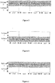
- an embodiment of the present disclosure provides a diagram of HARQ ID as shown in Figure 3 .
- the current BWP includes two subbands, DCI schedules 4 time slots, the starting HARQ ID is 0, and LBT detection succeeds in merely one subband (subband 2).
- the UE selects subband 2 to transmit PUSCH, and determines, based on the formula (1), that the HARQ IDs used by slot 0 to slot 3 are 0, 1, 2 and 3 respectively.
- an embodiment of the present disclosure provides another diagram of HARQ ID as shown in Figure 4 .
- the current BWP includes two subbands (subband 1 and subband 2), DCI schedules 4 time slots, the starting HARQ ID is 0, and LBT detection succeeds in both the two subbands.
- the UE selects subband 1 with a lower index value to transmit PUSCH, and determines, based on the formula (1), that the HARQ IDs used by slot 0 to slot 3 are 0, 1, 2 and 3 respectively.
- all the subbands where the LBT detection succeeds may be selected for uplink data transmission.
- using the frequency domain resource corresponding to the one or more subbands for uplink data transmission to transmit uplink data includes: performing LBT detection on the one or more subbands indicated by the downlink control information; and using the frequency domain resource corresponding to all the subbands where the LBT detection succeeds to transmit uplink data based on a result of the LBT detection.
- the subbands may correspond to the same PUSCH or different PUSCHs.
- the UE may select all subbands where the LBT detection succeeds from the subbands indicated through DCI by the base station to transmit the PUSCH, and the PUSCH transmitted in each subband is the same.
- using the frequency domain resource corresponding to all the subbands where the LBT detection succeeds to transmit uplink data further includes: determining a HARQ ID used by the PUSCH corresponding to the i-th time slot based on the formula (1).
- an embodiment of the present disclosure provides another diagram of HARQ ID as shown in Figure 5 .
- the current BWP includes two subbands, DCI schedules 4 time slots, the starting HARQ ID is 0, and LBT detection succeeds in merely one subband (subband 2).
- the UE selects subband 2 to transmit PUSCH, and determines, based on the formula (1), that the HARQ IDs used by slot 0 to slot 3 are 0, 1, 2 and 3 respectively.
- an embodiment of the present disclosure provides another diagram of HARQ ID as shown in Figure 6 .
- the current BWP includes two subbands (subband 1 and subband 2), DCI schedules 4 time slots, the starting HARQ ID is 0, and LBT detection succeeds in both the two subbands.
- the UE selects both the subband 1 and the subband 2 to transmit the same PUSCH, and determines, for the subband 1 and the subband 2 based on the formula (1), that the HARQ IDs used by slot 0 to slot 3 are 0, 1, 2 and 3 respectively.
- the different PUSCHs correspond to different HARQ-ID versions and/or different RV versions.
- the UE may select all subbands where the LBT detection succeeds from the subbands indicated through DCI to transmit the PUSCH, and each subband corresponds to one independent PUSCH.
- Modulation and Coding Schemes MCS
- MCS Modulation and Coding Schemes
- an embodiment of the present disclosure provides another diagram of HARQ ID as shown in Figure 7 .
- the current BWP includes two subbands, DCI schedules 4 time slots, the starting HARQ ID is 0, and LBT detection succeeds in merely one subband (subband 2).
- the UE selects subband 2 to transmit PUSCH, and determines, based on the formula (2), that the HARQ IDs used by slot 0 to slot 3 are 1, 3, 5 and 7 respectively.
- an embodiment of the present disclosure provides another diagram of HARQ ID as shown in Figure 8 .
- the current BWP includes two subbands (subband 1 and subband 2), DCI schedules 4 time slots, the starting HARQ ID is 0, and LBT detection succeeds in both the two subbands.
- the UE selects both the subband 1 and the subband 2 to transmit the same PUSCH, and determines, for the subband 2 based on the formula (2), that the HARQ IDs used by slot 0 to slot 3 are 1, 3, 5 and 7 respectively, and for the subband 1 based on the formula (2), that the HARQ IDs used by slot 0 to slot 3 are 0, 2, 4 and 6 respectively.
- the high-layer signaling is received from the base station, and then the downlink control information is received from the base station, so that the UE uses a frequency domain resource corresponding to the one or more subbands for uplink data transmission to transmit uplink data, based on frequency domain resource information corresponding to the one or more subbands for uplink data transmission.
- An uplink resource can be indicated in unit of subband, thereby improving resource utilization and performance of a NR network.
- an embodiment of the present disclosure further provides a base station capable of performing the uplink channel resource indication method as shown in Figure 10 .
- the base station 10 may include a first indication circuitry 101 and a second indication circuitry 102.
- the first indication circuitry 101 is configured to indicate frequency domain resource information corresponding to N subbands contained in a current carrier to a UE through high-layer signaling, where N>1.
- the second indication circuitry 102 is configured to indicate one or more subbands for uplink data transmission to the UE through downlink control information, so that the UE uses a frequency domain resource corresponding to the one or more subbands for uplink data transmission to transmit uplink data based on frequency domain resource information corresponding to the one or more subbands for uplink data transmission.
- the frequency domain resource information corresponding to the N subbands includes (N-1) CRB indexes, wherein the (N-1) CRB indexes are used for indicating a starting CRB of the N subbands.
- the second indication circuitry 102 is configured to indicate an index of the one or more subbands for uplink data transmission to the UE through a bitmap in the downlink control information.
- the second indication circuitry 102 is configured to indicate an index of the one or more subbands for uplink data transmission to the UE through a resource indication value in the downlink control information.
- the second indication circuitry 102 is configured to indicate a starting position and length of at least one interlaced resource cluster for uplink data transmission to the UE through a resource indication value in the downlink control information.
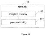
- an embodiment of the present disclosure further provides a terminal capable of performing the uplink channel resource determination method as shown in Figure 11 .
- the terminal 11 may include a reception circuitry 111 and a process circuitry 112.
- the reception circuitry 111 is configured to receive high-layer signaling from a base station, wherein the high-layer signaling includes frequency domain resource information corresponding to N subbands contained in a current carrier, where N>1.
- the process circuitry 112 is configured to receive downlink control information from the base station, wherein the downlink control information includes one or more subbands for uplink data transmission, and use a frequency domain resource corresponding to the one or more subbands for uplink data transmission to transmit uplink data, based on frequency domain resource information corresponding to the one or more subbands for uplink data transmission.
- the frequency domain resource information corresponding to the N subbands includes (N-1) CRB indexes, wherein the (N-1) CRB indexes are used for indicating a starting CRB of the N subbands.
- each of the one or more subbands for uplink data transmission corresponds to one PUSCH.
- the process circuitry 112 when the access mode of the PUSCH is long LBT, includes: a detection sub-circuitry (not shown), a selection sub-circuitry (not shown) and a first transmission sub-circuitry (not shown).
- the detection sub-circuitry is configured to perform LBT detection on the one or more subbands indicated by the downlink control information.
- the selection sub-circuitry is configured to select a subband where the LBT detection succeeds as a candidate subband based on a result of the LBT detection.
- the first transmission sub-circuitry is configured to use the frequency domain resource corresponding to the candidate subband to transmit uplink data.
- the selection sub-circuitry is configured to select, among subbands where the LBT detection succeeds, a subband with a smallest index value or a greatest index value as the candidate subband.
- the first transmission sub-circuitry is further configured to determine a HARQ ID used by the PUSCH corresponding to the i-th time slot based on the following formula: mod( n HARQ_ID + i,N HARQ ), where i is a relative index corresponding to a time slot for scheduling the PUSCH in the downlink control information, n HARQ_ID is a starting HARQ ID indicated in the downlink control information, N HARQ is a total number of HARQ IDs, and mod() is a remainder operator.
- the process circuitry 112 when the access mode of the PUSCH is long LBT, includes: a detection sub-circuitry (not shown) and a second transmission sub-circuitry (not shown).
- the detection sub-circuitry is configured to perform LBT detection on the one or more subbands indicated by the downlink control information.
- the second transmission sub-circuitry is configured to use the frequency domain resource corresponding to the one or more subbands where the LBT detection succeeds to transmit uplink data based on a result of the LBT detection.
- the one or more subbands correspond to the same PUSCH or different PUSCHs.
- the second transmission sub-circuitry is further configured to determine a HARQ ID used by the PUSCH corresponding to the i-th time slot based on the following formula: mod( n HARQ_ID + i,N HARQ ), where i is a relative index corresponding to a time slot for scheduling the PUSCH in the downlink control information, n HARQ_ID is a starting HARQ ID indicated in the downlink control information, N HARQ is a total number of HARQ IDs, and mod() is a remainder operator.
- the different PUSCHs correspond to different HARQ-ID versions and/or different RV versions.
- the second transmission sub-circuitry is further configured to determine a HARQ ID used by the PUSCH corresponding to the j-th subband based on the following formula: mod( n HARQ_ID + i ⁇ M + j,N HARQ ), where M is a total number of subbands contained in a current BWP, j is a subband index, j of 0 indicates the subband with a lowest frequency domain position, i is a relative index corresponding to a time slot for scheduling the PUSCH in the downlink control information, n HARQ_ID is a starting HARQ ID indicated in the downlink control information, N HARQ is a total number of HARQ IDs, and mod() is a remainder operator.
- a nonvalatile or nontransitory computer readable storage medium having computer instructions stored therein wherein when the computer instructions are executed, any one of the above uplink channel resource indication methods or the above uplink channel resource determination methods is performed.
- a base station including a memory and a processor
- the memory has computer instructions stored therein, and when the processor executes the computer instructions, any one of the above uplink channel resource indication methods is performed.
- a terminal including a memory and a processor
- the memory has computer instructions stored therein, and when the processor executes the computer instructions, any one of the above uplink channel resource determination methods is performed.
- the storage medium may include a Read Only Memory (ROM), a Random Access Memory (RAM), a magnetic disk or an optical disk.
Landscapes
- Engineering & Computer Science (AREA)
- Signal Processing (AREA)
- Computer Networks & Wireless Communication (AREA)
- Physics & Mathematics (AREA)
- Health & Medical Sciences (AREA)
- General Health & Medical Sciences (AREA)
- Spectroscopy & Molecular Physics (AREA)
- Mobile Radio Communication Systems (AREA)
Applications Claiming Priority (2)
| Application Number | Priority Date | Filing Date | Title |
|---|---|---|---|
| CN201810899832.XA CN110830194B (zh) | 2018-08-08 | 2018-08-08 | 上行信道资源的指示及确定方法、基站、终端、介质 |
| PCT/CN2019/092980 WO2020029698A1 (fr) | 2018-08-08 | 2019-06-26 | Procédé d'indication et de détermination de ressources de canal de liaison montante, et base station, terminal et support |
Publications (2)
| Publication Number | Publication Date |
|---|---|
| EP3836468A1 true EP3836468A1 (fr) | 2021-06-16 |
| EP3836468A4 EP3836468A4 (fr) | 2022-05-11 |
Family
ID=69413915
Family Applications (1)
| Application Number | Title | Priority Date | Filing Date |
|---|---|---|---|
| EP19848365.3A Pending EP3836468A4 (fr) | 2018-08-08 | 2019-06-26 | Procédé d'indication et de détermination de ressources de canal de liaison montante, et base station, terminal et support |
Country Status (4)
| Country | Link |
|---|---|
| US (1) | US11552773B2 (fr) |
| EP (1) | EP3836468A4 (fr) |
| CN (1) | CN110830194B (fr) |
| WO (1) | WO2020029698A1 (fr) |
Families Citing this family (8)
| Publication number | Priority date | Publication date | Assignee | Title |
|---|---|---|---|---|
| CN116528370A (zh) | 2017-06-16 | 2023-08-01 | 华为技术有限公司 | 一种通信方法及装置 |
| CN113225829B (zh) | 2018-04-04 | 2024-04-12 | 华为技术有限公司 | 一种发送、接收上行控制信息的方法及装置 |
| CN114616902A (zh) * | 2020-03-17 | 2022-06-10 | 北京小米移动软件有限公司 | 通信方法、装置、设备及可读存储介质 |
| WO2021195801A1 (fr) * | 2020-03-28 | 2021-10-07 | Qualcomm Incorporated | Ressources multiples dans des canaux de communication à faible latence dans une bande sans licence |
| CN115278785A (zh) * | 2020-04-10 | 2022-11-01 | 展讯通信(上海)有限公司 | 上行数据传输的子频带的确定方法、终端及可读存储介质 |
| CN115209556A (zh) * | 2021-04-08 | 2022-10-18 | 维沃移动通信有限公司 | 传输资源确定方法和设备 |
| CN115866757A (zh) * | 2021-09-24 | 2023-03-28 | 展讯通信(上海)有限公司 | 数据传输方向的指示方法及装置、通信装置 |
| CN116133123A (zh) * | 2021-11-12 | 2023-05-16 | 中国移动通信有限公司研究院 | 一种频域资源分配方法、装置及设备 |
Family Cites Families (16)
| Publication number | Priority date | Publication date | Assignee | Title |
|---|---|---|---|---|
| CN102404584B (zh) | 2010-09-13 | 2014-05-07 | 腾讯科技(成都)有限公司 | 调整场景左右摄像机的方法及装置、3d眼镜、客户端 |
| CN102404854B (zh) * | 2011-11-04 | 2018-04-06 | 中兴通讯股份有限公司 | 一种上行解调参考信号的资源配置方法及系统 |
| KR102413069B1 (ko) | 2015-01-09 | 2022-06-24 | 삼성전자주식회사 | 무선통신 시스템에서 단말을 위한 제어 채널 전송 방법 및 장치 |
| CN106507486B (zh) * | 2015-09-08 | 2020-04-28 | 华为技术有限公司 | 用于上行数据传输的方法、网络设备和终端设备 |
| CN106658742B (zh) | 2015-11-03 | 2020-07-03 | 中兴通讯股份有限公司 | 数据调度及传输的方法、装置及系统 |
| EP3407653B1 (fr) * | 2016-01-20 | 2021-12-29 | Ntt Docomo, Inc. | Terminal d'utilisateur, station de base sans fil et procédé de communication sans fil |
| CN105722229B (zh) | 2016-02-05 | 2019-08-27 | 北京佰才邦技术有限公司 | 信道的选择方法和装置 |
| WO2017171847A1 (fr) * | 2016-04-01 | 2017-10-05 | Nokia Solutions And Networks Oy | Transmission et multiplexage de préambules de rach avec des données et/ou des signaux de commande |
| KR102329949B1 (ko) * | 2016-07-05 | 2021-11-23 | 한국전자통신연구원 | 뉴머롤러지를 이용한 전송 방법 및 장치, 그리고 뉴머롤러지를 이용한 스케줄링 방법 및 장치 |
| CN107743315B (zh) * | 2016-08-11 | 2022-01-11 | 上海诺基亚贝尔股份有限公司 | 用于基于竞争的传输的方法和设备 |
| WO2018084660A1 (fr) * | 2016-11-04 | 2018-05-11 | 엘지전자 주식회사 | Procédé d'émission/réception de canal de commande de liaison montante physique entre un terminal et une station de base dans un système de communication sans fil et dispositif prenant en charge ledit procédé |
| CN108076518B (zh) | 2016-11-17 | 2021-01-05 | 华为技术有限公司 | 一种上行数据传输方法及设备 |
| WO2018128938A1 (fr) * | 2017-01-09 | 2018-07-12 | Intel IP Corporation | Adaptation de largeur de bande destinée à un système de communication sans fil |
| US11229031B2 (en) * | 2017-12-16 | 2022-01-18 | Lg Electronics Inc. | Uplink control information transmitting method in wireless communication system and device using method |
| US10873423B2 (en) * | 2018-02-15 | 2020-12-22 | Huawei Technologies Co., Ltd. | Systems and methods for allocation of uplink control channel resources in unlicensed spectrum |
| US11184776B2 (en) * | 2018-07-16 | 2021-11-23 | Kt Corporation | Method and apparatus for performing wireless communication in unlicensed band |
-
2018
- 2018-08-08 CN CN201810899832.XA patent/CN110830194B/zh active Active
-
2019
- 2019-06-26 EP EP19848365.3A patent/EP3836468A4/fr active Pending
- 2019-06-26 WO PCT/CN2019/092980 patent/WO2020029698A1/fr unknown
- 2019-06-26 US US17/265,860 patent/US11552773B2/en active Active
Also Published As
| Publication number | Publication date |
|---|---|
| US20210176028A1 (en) | 2021-06-10 |
| CN110830194A (zh) | 2020-02-21 |
| WO2020029698A1 (fr) | 2020-02-13 |
| CN110830194B (zh) | 2020-10-30 |
| US11552773B2 (en) | 2023-01-10 |
| EP3836468A4 (fr) | 2022-05-11 |
Similar Documents
| Publication | Publication Date | Title |
|---|---|---|
| US11552773B2 (en) | Uplink channel resource indication method, uplink channel resource determination method, base station, terminal and medium | |
| US10687320B2 (en) | Data sending method, data receiving method, base station and user equipment | |
| US20210099987A1 (en) | Allocating transmission resources in communication networks that provide low latency services | |
| US9191824B2 (en) | Sharing frequencies in an OFDM-based wireless communication system | |
| EP3110195A1 (fr) | Station de base, et procédé et dispositif pour l'ordonnancement sur le spectre sans licence dans un ue | |
| CN107836134B (zh) | 上行信息的发送方法、装置和用户设备 | |
| US11330568B2 (en) | Uplink control information transmitting method, device, storage medium, and user equipment | |
| JP2020536419A (ja) | リソース割り当て特定方法、リソース割り当て指示方法、端末およびネットワーク側機器 | |
| EP3606231B1 (fr) | Procédé et appareil de transmission sans planification | |
| EP3955676A1 (fr) | Procédé de communication et dispositif de communication | |
| EP3637644A1 (fr) | Procédé de saisie de données, dispositif associé et système. | |
| CN107567105B (zh) | 一种pucch资源的调度方法和装置 | |
| US10581574B2 (en) | Data transmission method, and apparatus | |
| US11438875B2 (en) | Signaling receiving method and related device | |
| EP3618537B1 (fr) | Procédé et appareil de transmission de message, dispositif terminal et station de base | |
| CN108811090B (zh) | 一种资源分配指示方法、装置、网络侧设备及用户设备 | |
| EP3902307A1 (fr) | Procédé et appareil de transmission d'informations de commande de liaison montante, support d'informations et terminal utilisateur | |
| CN112533289B (zh) | 上行控制信息传输方法、终端、电子设备和存储介质 | |
| CN107615850B (zh) | 传输数据的方法及装置及用户设备 | |
| CN113783674A (zh) | 一种将调制符号的映射到分配子帧的方法 | |
| CN113518390B (zh) | 上行数据传输方法、终端及可读存储介质 | |
| CN114257330B (zh) | Lte230系统的资源调度方法及装置 | |
| WO2023010384A1 (fr) | Rétroaction de csi pour une transmission multi-pdsch | |
| EP3780819A1 (fr) | Procédé et appareil d'attribution de sous-bandes de programmation, et dispositif et support d'informations lisible | |
| CN114760698A (zh) | Pucch资源分配方法和装置 |
Legal Events
| Date | Code | Title | Description |
|---|---|---|---|
| STAA | Information on the status of an ep patent application or granted ep patent |
Free format text: STATUS: THE INTERNATIONAL PUBLICATION HAS BEEN MADE |
|
| STAA | Information on the status of an ep patent application or granted ep patent |
Free format text: STATUS: THE INTERNATIONAL PUBLICATION HAS BEEN MADE |
|
| PUAI | Public reference made under article 153(3) epc to a published international application that has entered the european phase |
Free format text: ORIGINAL CODE: 0009012 |
|
| STAA | Information on the status of an ep patent application or granted ep patent |
Free format text: STATUS: REQUEST FOR EXAMINATION WAS MADE |
|
| 17P | Request for examination filed |
Effective date: 20210121 |
|
| AK | Designated contracting states |
Kind code of ref document: A1 Designated state(s): AL AT BE BG CH CY CZ DE DK EE ES FI FR GB GR HR HU IE IS IT LI LT LU LV MC MK MT NL NO PL PT RO RS SE SI SK SM TR |
|
| DAV | Request for validation of the european patent (deleted) | ||
| DAX | Request for extension of the european patent (deleted) | ||
| A4 | Supplementary search report drawn up and despatched |
Effective date: 20220408 |
|
| RIC1 | Information provided on ipc code assigned before grant |
Ipc: H04W 74/08 20090101ALN20220404BHEP Ipc: H04W 72/04 20090101ALN20220404BHEP Ipc: H04W 72/12 20090101ALI20220404BHEP Ipc: H04L 27/00 20060101ALI20220404BHEP Ipc: H04L 1/18 20060101ALI20220404BHEP Ipc: H04L 5/00 20060101AFI20220404BHEP |
|
| STAA | Information on the status of an ep patent application or granted ep patent |
Free format text: STATUS: EXAMINATION IS IN PROGRESS |
|
| 17Q | First examination report despatched |
Effective date: 20230220 |
|
| GRAP | Despatch of communication of intention to grant a patent |
Free format text: ORIGINAL CODE: EPIDOSNIGR1 |
|
| STAA | Information on the status of an ep patent application or granted ep patent |
Free format text: STATUS: GRANT OF PATENT IS INTENDED |
|
| RIC1 | Information provided on ipc code assigned before grant |
Ipc: H04W 72/23 20230101ALN20240307BHEP Ipc: H04W 74/0808 20240101ALN20240307BHEP Ipc: H04W 72/0453 20230101ALN20240307BHEP Ipc: H04L 1/1867 20230101ALI20240307BHEP Ipc: H04L 1/1822 20230101ALI20240307BHEP Ipc: H04W 72/12 20090101ALI20240307BHEP Ipc: H04L 27/00 20060101ALI20240307BHEP Ipc: H04L 1/1812 20230101ALI20240307BHEP Ipc: H04L 5/00 20060101AFI20240307BHEP |
|
| INTG | Intention to grant announced |
Effective date: 20240320 |
|
| RIC1 | Information provided on ipc code assigned before grant |
Ipc: H04L 27/00 20060101ALI20240308BHEP Ipc: H04L 1/1812 20230101ALI20240308BHEP Ipc: H04L 5/00 20060101AFI20240308BHEP Ipc: H04W 72/23 20230101ALN20240308BHEP Ipc: H04W 74/0808 20240101ALN20240308BHEP Ipc: H04W 72/0453 20230101ALN20240308BHEP Ipc: H04L 1/1867 20230101ALI20240308BHEP Ipc: H04L 1/1822 20230101ALI20240308BHEP Ipc: H04W 72/12 20090101ALI20240308BHEP |