EP3835821A1 - Method and device for determining a safe distance - Google Patents
Method and device for determining a safe distance Download PDFInfo
- Publication number
- EP3835821A1 EP3835821A1 EP19215728.7A EP19215728A EP3835821A1 EP 3835821 A1 EP3835821 A1 EP 3835821A1 EP 19215728 A EP19215728 A EP 19215728A EP 3835821 A1 EP3835821 A1 EP 3835821A1
- Authority
- EP
- European Patent Office
- Prior art keywords
- tag
- transponder
- resp
- poll
- safe
- Prior art date
- Legal status (The legal status is an assumption and is not a legal conclusion. Google has not performed a legal analysis and makes no representation as to the accuracy of the status listed.)
- Pending
Links
- 238000000034 method Methods 0.000 title claims abstract description 38
- 230000005540 biological transmission Effects 0.000 claims abstract description 14
- 238000004891 communication Methods 0.000 claims abstract description 9
- 238000012545 processing Methods 0.000 claims abstract description 4
- 101000651958 Crotalus durissus terrificus Snaclec crotocetin-1 Proteins 0.000 claims description 15
- 101100258328 Neurospora crassa (strain ATCC 24698 / 74-OR23-1A / CBS 708.71 / DSM 1257 / FGSC 987) crc-2 gene Proteins 0.000 claims description 13
- 238000005259 measurement Methods 0.000 claims description 7
- 230000004224 protection Effects 0.000 description 13
- 238000011161 development Methods 0.000 description 8
- 230000018109 developmental process Effects 0.000 description 8
- 230000001681 protective effect Effects 0.000 description 6
- 238000013459 approach Methods 0.000 description 3
- 230000004807 localization Effects 0.000 description 3
- 230000009885 systemic effect Effects 0.000 description 2
- 101100392078 Caenorhabditis elegans cat-4 gene Proteins 0.000 description 1
- 101000879673 Streptomyces coelicolor Subtilisin inhibitor-like protein 3 Proteins 0.000 description 1
- 230000032683 aging Effects 0.000 description 1
- 230000009286 beneficial effect Effects 0.000 description 1
- 238000013461 design Methods 0.000 description 1
- 238000001514 detection method Methods 0.000 description 1
- 230000000694 effects Effects 0.000 description 1
- 230000000704 physical effect Effects 0.000 description 1
- 230000009979 protective mechanism Effects 0.000 description 1
- 230000001960 triggered effect Effects 0.000 description 1
- 230000000007 visual effect Effects 0.000 description 1
Images


Classifications
-
- G—PHYSICS
- G01—MEASURING; TESTING
- G01S—RADIO DIRECTION-FINDING; RADIO NAVIGATION; DETERMINING DISTANCE OR VELOCITY BY USE OF RADIO WAVES; LOCATING OR PRESENCE-DETECTING BY USE OF THE REFLECTION OR RERADIATION OF RADIO WAVES; ANALOGOUS ARRANGEMENTS USING OTHER WAVES
- G01S11/00—Systems for determining distance or velocity not using reflection or reradiation
- G01S11/02—Systems for determining distance or velocity not using reflection or reradiation using radio waves
-
- F—MECHANICAL ENGINEERING; LIGHTING; HEATING; WEAPONS; BLASTING
- F16—ENGINEERING ELEMENTS AND UNITS; GENERAL MEASURES FOR PRODUCING AND MAINTAINING EFFECTIVE FUNCTIONING OF MACHINES OR INSTALLATIONS; THERMAL INSULATION IN GENERAL
- F16P—SAFETY DEVICES IN GENERAL; SAFETY DEVICES FOR PRESSES
- F16P3/00—Safety devices acting in conjunction with the control or operation of a machine; Control arrangements requiring the simultaneous use of two or more parts of the body
- F16P3/12—Safety devices acting in conjunction with the control or operation of a machine; Control arrangements requiring the simultaneous use of two or more parts of the body with means, e.g. feelers, which in case of the presence of a body part of a person in or near the danger zone influence the control or operation of the machine
- F16P3/14—Safety devices acting in conjunction with the control or operation of a machine; Control arrangements requiring the simultaneous use of two or more parts of the body with means, e.g. feelers, which in case of the presence of a body part of a person in or near the danger zone influence the control or operation of the machine the means being photocells or other devices sensitive without mechanical contact
- F16P3/147—Safety devices acting in conjunction with the control or operation of a machine; Control arrangements requiring the simultaneous use of two or more parts of the body with means, e.g. feelers, which in case of the presence of a body part of a person in or near the danger zone influence the control or operation of the machine the means being photocells or other devices sensitive without mechanical contact using electro-magnetic technology, e.g. tags or radar
-
- G—PHYSICS
- G01—MEASURING; TESTING
- G01S—RADIO DIRECTION-FINDING; RADIO NAVIGATION; DETERMINING DISTANCE OR VELOCITY BY USE OF RADIO WAVES; LOCATING OR PRESENCE-DETECTING BY USE OF THE REFLECTION OR RERADIATION OF RADIO WAVES; ANALOGOUS ARRANGEMENTS USING OTHER WAVES
- G01S13/00—Systems using the reflection or reradiation of radio waves, e.g. radar systems; Analogous systems using reflection or reradiation of waves whose nature or wavelength is irrelevant or unspecified
- G01S13/74—Systems using reradiation of radio waves, e.g. secondary radar systems; Analogous systems
-
- G—PHYSICS
- G06—COMPUTING; CALCULATING OR COUNTING
- G06F—ELECTRIC DIGITAL DATA PROCESSING
- G06F21/00—Security arrangements for protecting computers, components thereof, programs or data against unauthorised activity
- G06F21/60—Protecting data
- G06F21/64—Protecting data integrity, e.g. using checksums, certificates or signatures
- G06F21/645—Protecting data integrity, e.g. using checksums, certificates or signatures using a third party
-
- H—ELECTRICITY
- H04—ELECTRIC COMMUNICATION TECHNIQUE
- H04W—WIRELESS COMMUNICATION NETWORKS
- H04W12/00—Security arrangements; Authentication; Protecting privacy or anonymity
- H04W12/10—Integrity
- H04W12/104—Location integrity, e.g. secure geotagging
-
- H—ELECTRICITY
- H04—ELECTRIC COMMUNICATION TECHNIQUE
- H04W—WIRELESS COMMUNICATION NETWORKS
- H04W12/00—Security arrangements; Authentication; Protecting privacy or anonymity
- H04W12/60—Context-dependent security
- H04W12/61—Time-dependent
-
- H—ELECTRICITY
- H04—ELECTRIC COMMUNICATION TECHNIQUE
- H04W—WIRELESS COMMUNICATION NETWORKS
- H04W4/00—Services specially adapted for wireless communication networks; Facilities therefor
- H04W4/02—Services making use of location information
- H04W4/029—Location-based management or tracking services
-
- G—PHYSICS
- G01—MEASURING; TESTING
- G01S—RADIO DIRECTION-FINDING; RADIO NAVIGATION; DETERMINING DISTANCE OR VELOCITY BY USE OF RADIO WAVES; LOCATING OR PRESENCE-DETECTING BY USE OF THE REFLECTION OR RERADIATION OF RADIO WAVES; ANALOGOUS ARRANGEMENTS USING OTHER WAVES
- G01S13/00—Systems using the reflection or reradiation of radio waves, e.g. radar systems; Analogous systems using reflection or reradiation of waves whose nature or wavelength is irrelevant or unspecified
- G01S13/87—Combinations of radar systems, e.g. primary radar and secondary radar
- G01S13/876—Combination of several spaced transponders or reflectors of known location for determining the position of a receiver
-
- G—PHYSICS
- G06—COMPUTING; CALCULATING OR COUNTING
- G06F—ELECTRIC DIGITAL DATA PROCESSING
- G06F2221/00—Indexing scheme relating to security arrangements for protecting computers, components thereof, programs or data against unauthorised activity
- G06F2221/21—Indexing scheme relating to G06F21/00 and subgroups addressing additional information or applications relating to security arrangements for protecting computers, components thereof, programs or data against unauthorised activity
- G06F2221/2111—Location-sensitive, e.g. geographical location, GPS
-
- G—PHYSICS
- G06—COMPUTING; CALCULATING OR COUNTING
- G06F—ELECTRIC DIGITAL DATA PROCESSING
- G06F2221/00—Indexing scheme relating to security arrangements for protecting computers, components thereof, programs or data against unauthorised activity
- G06F2221/21—Indexing scheme relating to G06F21/00 and subgroups addressing additional information or applications relating to security arrangements for protecting computers, components thereof, programs or data against unauthorised activity
- G06F2221/2151—Time stamp
-
- H—ELECTRICITY
- H04—ELECTRIC COMMUNICATION TECHNIQUE
- H04L—TRANSMISSION OF DIGITAL INFORMATION, e.g. TELEGRAPHIC COMMUNICATION
- H04L1/00—Arrangements for detecting or preventing errors in the information received
- H04L1/004—Arrangements for detecting or preventing errors in the information received by using forward error control
- H04L1/0056—Systems characterized by the type of code used
- H04L1/0061—Error detection codes
-
- H—ELECTRICITY
- H04—ELECTRIC COMMUNICATION TECHNIQUE
- H04W—WIRELESS COMMUNICATION NETWORKS
- H04W12/00—Security arrangements; Authentication; Protecting privacy or anonymity
- H04W12/30—Security of mobile devices; Security of mobile applications
- H04W12/33—Security of mobile devices; Security of mobile applications using wearable devices, e.g. using a smartwatch or smart-glasses
-
- H—ELECTRICITY
- H04—ELECTRIC COMMUNICATION TECHNIQUE
- H04W—WIRELESS COMMUNICATION NETWORKS
- H04W4/00—Services specially adapted for wireless communication networks; Facilities therefor
- H04W4/02—Services making use of location information
- H04W4/023—Services making use of location information using mutual or relative location information between multiple location based services [LBS] targets or of distance thresholds
-
- H—ELECTRICITY
- H04—ELECTRIC COMMUNICATION TECHNIQUE
- H04W—WIRELESS COMMUNICATION NETWORKS
- H04W4/00—Services specially adapted for wireless communication networks; Facilities therefor
- H04W4/90—Services for handling of emergency or hazardous situations, e.g. earthquake and tsunami warning systems [ETWS]
Definitions
- the invention relates to a method and a device for determining a safe distance according to the TWR principle between a wirelessly communicating object transponder and at least one anchor gateway, each of which has means for recording time stamps.
- protective fences are often used for personal protection, for example to protect operating personnel or moving objects from a moving assembly robot arm that is in operation.
- a virtual protective fence for dangerous production machines can be implemented with a laser distance measurement or visual recognition with cameras, but this is usually very complex, inflexible and expensive.
- the localization of a wirelessly communicating object transponder i.e. the calculation of an absolute position in space (2D or 3D) by a radio-based localization system with standard components is, however, considered unsafe in the prior art.
- the calculated position can be falsified by hardware and / or software errors in the components used or by physical effects that can be caused, for example, by the radio channel.
- Such effects can be caused by radio channels that are not based on a direct line of sight.
- Signal reflections can lead to multipath propagation and subsequently to multiple reception of the same transmission signal, but with different transit times.
- the known TWR method (“Two Way Ranging”) can be used to improve the transit time measurement.
- the two-way distance method determines the signal propagation time (flight time) of the UWB RF signal and then calculates the distance between nodes by multiplying the time by the speed of light.
- the TWR process is used between a transponder and a requested anchor, only one anchor should be involved in the TWR at a given time.
- An anchor is understood to be a stationary radio unit with a known position.
- the object of the invention is to provide a method and a device for determining a safe distance between a wirelessly communicating object transponder and an anchor gateway.
- the wirelessly communicating object transponder can be carried, for example, by a person, that is to say the operating personnel.
- an object such as an autonomously driving vehicle with an object transponder can also be used be equipped to protect this vehicle from a collision, for example.
- the protection zone is a virtual zone which can be used to ensure that a protective mechanism is activated when this zone is interfered with, for example by immediately stopping the intervening object such as a robot arm.
- the protection radius of the protection zone describes the minimum radius in which the transponder is definitely located, that is, reliably not outside.
- a fail-safe computing unit as a safety-certified component carries out the same computing operations, for example using two independent computing devices, compares their results with one another and, if they match, provides a result that is considered to be safe.
- a fail-safe computing unit can execute safety-relevant and non-safety-relevant application programs and is certified up to SIL3 according to IEC 61508 and Cat4 PLd according to ISO 13849-1.
- the IEC 61508 is an international series of standards for the development of electrical, electronic and programmable electronic systems that perform a safety function. It is published by the International Electrotechnical Commission (IEC) and bears the title Functional safety of safety-related electrical / electronic / programmable electronic systems.
- IEC International Electrotechnical Commission
- the EN ISO 13849 standard is a safety-specific standard that deals with design principles for safety-related parts of control systems.
- the wireless communication between the object transponder and the one anchor gateway for a localization query, a query, a response and an end message is sent and received.
- the method can be based on a simple and known method for two-way measurement.
- a process number is generated by the fail-safe computing device, which is transmitted with the response message.
- the process number is a random number.
- control information is parity information.
- a communication address of the object transponder or of the at least one anchor gateway is taken into account when calculating the control information.
- a further development of the invention provides that safe distances are determined at a first and a second point in time, from which a movement speed of the transponder is determined, and the movement speed is compared with a predefined limit value.
- the object of the invention is also achieved by a device of the type mentioned at the beginning which is set up to carry out the steps of the method according to the invention.
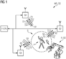
- Fig. 1 an embodiment of a warning and protection system is shown.
- a respective query signal P1-P3 is emitted into a radio channel, which includes a query message MP (English "Poll").
- the respective query signal P1-P3 is received by the respective gateway G1-G3 from the radio channel, processed further and emitted again as the respective response signal R1-R3, which a respective response message MR (English “response”) comprises.
- the response signals R1-R3 are received by the object transponder T, processed further and emitted as the respective end signal F1-F3 back into the radio channel, which comprises the respective response message MF (English "final”).
- the end signals F1-F3 are received by the respective gateway G1-G3 and transferred to a fail-safe computing device F-CPU, which determines the protection radius r P of a protection zone S.
- a hazard system is in operation, for example in the form of a production plant, and a robot arm R of the production plant intervenes in the protection zone S, a termination process for its operation is triggered for the robot arm, whereby the robot arm comes to a standstill immediately.
- the intervention in the protection zone S can take place, for example, in that the person P approaches the robot arm R in an unauthorized manner, and personal protection is no longer reliably guaranteed.
- a method for determining a safe distance d TWR according to the TWR principle between a wirelessly communicating object transponder T and at least one anchor gateway G1-G3, each of which has means for recording time stamps, is described below using an exemplary embodiment of the invention .
- a query, a response and an end message MP, MR, MF are sent and received between the object transponder T and the at least one anchor gateway G1-G3 for a location query.
- a process number RNR can be generated by the fail-safe computing device F-CPU, which is transmitted with the response message MR.
- the transaction number RNR is, for example, a random number.
- an address of the object transponder T or of the at least one anchor gateway G1-G3 can also be taken into account.
- Fig. 2 represents an example of a flow chart for determining the safe distance d TWR , on the basis of which the invention is described in detail.
- a safe distance is a distance that is determined without systemic errors when measuring the transit time.
- Undesired influences for example due to a fluctuating or inaccurate time base, which can occur when measuring the transit time of signals, are systemically excluded by a corresponding "safe" calculation.
- the position of the object transponder T (also called "tag") in a three-dimensional space is to be determined according to the further explanations, the anchor or gateway transponders G1, G2, G3 with a known position being used.
- the query message MP is sent on the transponder T or day at a time with a time stamp TS TAG_TX_POLL and received at the respective anchor gateway G1-G3 at a time with a time stamp TS GW_RX_POLL .
- the transmission of the query message MP in the radio channel between the transponder T and the respective gateway of the three gateways G1-G3 requires a duration TOF 1 (English "time-of-flight").
- the query message MP is processed by the anchor gateway within a time span T GW_REPLY and a corresponding response message MR is sent from the anchor gateway to the transponder T at a point in time with a time stamp TS GW_TX_RESP and received on the day at a point in time with a time stamp TS TAG_RX_RESP .
- the time span T GW_REPLY is determined by the clock rate of the gateway component T GW_CLK and is known within certain known limits.
- T GW_REPLY TS GW_TX_RESP - TS GW_RX_POLL
- T Round1 denotes the signal propagation time between the time stamp TS TAG_TX_POLL and the time stamp TS TAG_RX_RESP .
- T Round 1 TS TAG_RX_RESP - TS TAG_TX_POLL
- the response message MR is processed by the tag within a time span T TAG_REPLY and a corresponding end message MF is sent from the anchor gateway to the transponder T at a time with a time stamp TS TAG_TX_FINAL .
- the time span T TAG_REPLY is determined by the clock rate of the gateway component T TAG_CLK and is known within certain known limits.
- the anchor gateway receives the end message MF at a point in time with a time stamp TS GW_RX_FINAL .
- T Round2 denotes the signal propagation time between the time stamp TS GW_TX_RESP and the time stamp TS GW_RX_FINAL .
- T Round 2 TS GW_RX_FINAL - TS GW_TX_RESP
- T TAG_REPLY TS TAG_TX_FINAL - TS TAG_RX_RESP
- the time stamps are recorded by a tag counter CT in the object transponder or a gateway counter CG in the anchor transponder.
- the computing device F-CPU can now recognize a first error, provided that the time stamps required for the distance calculation of the transponder and the gateway are falsified.
- a systemic error is understood to be an error which has an unfavorable influence on the generation or recording of time stamps, for example an undesirably different time base in an electronic component, which can be caused by changing temperature, aging, component tolerances or the like.
- Such an error can occur between individual components in a system, such as the transponder T and a gateway G1-G3, in that a local time base changes unevenly in the form of a clock generation for a digital electronic circuit.
- Time stamps or a drift of a respective timer cycle in a component such as the transponder T1 or the gateways G1-G3 are independent of one another. As a result, an error only affects its own timestamp and not that of the other components.
- TWR has an integrated error detection.
- T Round 1 2 ⁇ TPF + T GW_REPLY
- T Round 2 2 ⁇ TOF + T TAG_REPLY
- safe_twr_value T Round 1 - T GW_REPLY - T Round 2 - T TAG_REPLY 2
- a program P_T of the transponder T with method steps PT1-PT3 for the transponder T is also shown in simplified form as part of the flowchart.
- a program P_G of a respective gateway G1-G3 with method steps PG1-PG3 for the respective gateway G1-G3 can be seen, as well as a program P_F of the fail-safe computing device F-CPU with method steps PF1-PF4 for the computing device F-CPU.
- step PT1 the query message MP is initiated by the transponder T and sent.
- the respective gateway receives the query message MP in step PG1 and determines the sending time for the response message MR.
- step PF1 a random number RNR is generated by the fail-safe computing device F-CPU and sent to the respective gateway.
- the gateway sends a response message MR in step PG2 to the transponder T, which contains the random number RNR.
- the response message MR is received in step PT2 by the transponder T and the transmission time for the end message MF is calculated.
- the transponder T determines a first checksum CRC1 from the time stamps and the address of the transponder T and the random number and sends an end message MF from the transponder T to the gateway, which contains the first checksum CRC1.
- step PG3 the gateway receives the end message MF and determines a second checksum CRC2 from the time stamps and the address of the gateway and the first checksum CRC1 and transmits the time stamps and the address of the gateway and the transponder T, as well as the second checksum CRC2 the F-CPU device.
- step PF2 the device F-CPU calculates a third checksum CRC3 and compares it with the second checksum CRC2.
- step PF3 the device F-CPU calculates a safe value safe_twr_value for the distance between the gateway and the transponder T by means of the TWR method and checks the values for plausibility.
- step PF4 the device F-CPU calculates the safe distance sought on the basis of the previous relationship with regard to the signal propagation time in the radio channel TOF.
- Fig. 3 represents an example of an interrogation message MP_TWR according to the prior art for TWR, which includes data elements for a sequence number MPSN, a destination address MPZA, a source address MPQA and a function code MPFC, and for example also as an interrogation message MP can be used in the method according to the invention.
- Fig. 4 represents an example of a response message MR_TWR according to the prior art for TWR, which includes data elements for a sequence number MRSN, a destination address MRZA, a source address MRQA and a function code MRFC.
- Fig. 5 represents an example of the response message MR according to the invention, which includes data elements for a sequence number MRSN, a destination address MRZA, a source address MRQA and a function code MRFC.
- the function code MRFC can differ from the prior art.
- the random number RNR is also included.
- Fig. 6 shows an example of the end message MF according to the prior art for TWR, which includes data elements for a sequence number MFSN, a destination address MFZA, a source address MFQA and a function code MFFC.
- the function code MFFC can differ from that from the prior art.
- the end message MF has a data element for a time difference MFRXTX, which denotes the time between the sending of the query message MP and the receipt of the response message MR by the transponder T.
- the end message MF has a data element for a time difference MFTXRX, which denotes the time between the receipt of the response message MR and the sending of the end message MF by the transponder T.
- Fig. 7 shows an example of the end message MP according to the invention, which includes data elements for a sequence number MPSN, a destination address MPZA, a source address MPQA and a function code MPFC.
- the function code MFFC can differ from that from the prior art.
- the end message MP also contains a data element in each case in the form of a time stamp for a query send time MF_PTX, a response receive time MF_RRX, and an end send time MF_FTX.
- the end message MP has the first checksum CRC1, which is formed using the time stamp of the transponder T and the random number RNR.
Abstract
Verfahren zur Bestimmung einer sicheren Distanz nach dem TWR-Prinzip zwischen einem drahtlos kommunizierenden Objekt-Transponder (T) und zumindest einem Anker-Gateway (G1-G3), welche jeweils Mittel zur Erfassung von Zeitstempeln aufweisen, dadurch gekennzeichnet, dass folgende Schritte ausgeführt werden:a) Erfassen von Sende- und Empfangs-Zeitstempeln für eine jeweilige Kommunikations-Nachricht seitens des Transponders (T) und des zumindest einen Anker-Gateways (G1-G3),b) Übertragen der jeweiligen Zeitstempel vom Transponder (T) und dem zumindest einen Anker-Gateway (G1-G3) mit zumindest einer jeweiligen Kontrollinformation an eine fehlersichere Rechenvorrichtung (F-CPU),c) Durchführen von zumindest einer Überprüfung durch die fehlersichere Rechenvorrichtung (F-CPU) ausgewählt aus:c1) Überprüfung der Richtigkeit der jeweiligen Zeitstempel anhand der zumindest einen Kontrollinformation,c2) Überprüfung der errechneten Zeitdauer für die Bearbeitungszeiten des Transponders (T) und jener des zumindest einen Anker-Gateways (G1-G3) anhand bekannter Erfahrungswerte,d) Bestimmen der sicheren Distanz mithilfe der überprüften Zeitstempel durch die fehlersichere Rechenvorrichtung (F-CPU),wobei bei der Erfassung der Zeitstempel Zeitstempel-Fehler nur durch den Transponder (T) oder alternativ nur durch das eine Anker-Gateway (G1-G3) hervorgerufen werden.Method for determining a safe distance according to the TWR principle between a wirelessly communicating object transponder (T) and at least one anchor gateway (G1-G3), each of which has means for recording time stamps, characterized in that the following steps are carried out : a) Acquisition of send and receive time stamps for a respective communication message on the part of the transponder (T) and the at least one anchor gateway (G1-G3), b) transmission of the respective time stamps from the transponder (T) and the at least an anchor gateway (G1-G3) with at least one respective control information to a fail-safe computing device (F-CPU), c) performing at least one check by the fail-safe computing device (F-CPU) selected from: c1) checking the correctness of the respective Time stamp based on the at least one control information item, c2) checking the calculated time period for the processing times of the transponder (T) and that de s At least one anchor gateway (G1-G3) based on known empirical values, d) Determination of the safe distance with the help of the checked time stamps by the fail-safe computing device (F-CPU), with time stamp errors only being caused by the transponder (T ) or alternatively only through the one anchor gateway (G1-G3).
Description
Die Erfindung betrifft ein Verfahren und eine Vorrichtung zur Bestimmung einer sicheren Distanz nach dem TWR-Prinzip zwischen einem drahtlos kommunizierenden Objekt-Transponder und zumindest einem Anker-Gateway, welche jeweils Mittel zur Erfassung von Zeitstempeln aufweisen.The invention relates to a method and a device for determining a safe distance according to the TWR principle between a wirelessly communicating object transponder and at least one anchor gateway, each of which has means for recording time stamps.
In Produktionssystemen werden häufig Schutzzäune zum Personenschutz eingesetzt, um beispielsweise Bedienungspersonal oder bewegte Objekte vor einem, in Betrieb befindlichen, bewegten Montage-Roboterarm zu schützen.In production systems, protective fences are often used for personal protection, for example to protect operating personnel or moving objects from a moving assembly robot arm that is in operation.
Schutzzäune benötigen allerdings Platz in der Produktionsanlage und können den Zugang zu Anlagen erschweren. Damit sind indirekt Produktionskosten verbunden, welche einen wirtschaftlichen Betrieb eines Produktionssystems unerwünscht beeinträchtigen.Protective fences, however, require space in the production plant and can make access to the plant more difficult. This is indirectly linked to production costs which undesirably impair the economic operation of a production system.
Beispielsweise kann mit einer Laserentfernungsmessung oder visueller Erkennung mit Kameras ein virtueller Schutzzaun für gefährliche Produktionsmaschinen realisiert werden, was jedoch in der Regel sehr aufwändig, unflexibel und teuer ist.For example, a virtual protective fence for dangerous production machines can be implemented with a laser distance measurement or visual recognition with cameras, but this is usually very complex, inflexible and expensive.
Die Lokalisierung eines drahtlos kommunizierenden Objekt-Transponders, also die Berechnung einer absoluten Position im Raum (2D oder 3D) durch ein funkbasiertes Lokalisierungssystem mit Standardkomponenten gilt im Stand der Technik allerdings als unsicher.The localization of a wirelessly communicating object transponder, i.e. the calculation of an absolute position in space (2D or 3D) by a radio-based localization system with standard components is, however, considered unsafe in the prior art.
Die berechnete Position kann durch Hardware- und/oder Software-Fehler der zum Einsatz kommenden Komponenten oder durch physikalische Effekte, welche beispielsweise durch den Funckanal hervorgerufen werden können, verfälscht werden.The calculated position can be falsified by hardware and / or software errors in the components used or by physical effects that can be caused, for example, by the radio channel.
Solche Effekte können durch Funkkanäle, welche auf keiner direkten Sichtverbindung basieren, hervorgerufen werden. Durch Signalreflektionen kann es zu Mehrwegausbreitung und in weiterer Folge zum Mehrfachempfang desselben Sendesignals, jedoch mit unterschiedlichen Laufzeiten kommen.Such effects can be caused by radio channels that are not based on a direct line of sight. By Signal reflections can lead to multipath propagation and subsequently to multiple reception of the same transmission signal, but with different transit times.
Eine Verbesserung der Laufzeitmessung kann durch das bekannte TWR-Verfahren (englisch "Two Way Ranging", Zweiwege-Entfernungsmethode) erreicht werden. Die Zweiwege-Entfernungsmethode bestimmt die Signallaufzeit (Flugzeit) des UWB-HF-Signals und berechnet dann die Entfernung zwischen den Knoten, indem die Zeit mit der Lichtgeschwindigkeit multipliziert wird. Der TWR-Prozess wird zwischen einem Transponder und einem angeforderten Anker angewendet, es soll zu einem bestimmten Zeitpunkt nur ein Anker am TWR beteiligt sein. Unter einem Anker wird eine stationäre Funkeinheit mit bekannter Position verstanden.The known TWR method ("Two Way Ranging") can be used to improve the transit time measurement. The two-way distance method determines the signal propagation time (flight time) of the UWB RF signal and then calculates the distance between nodes by multiplying the time by the speed of light. The TWR process is used between a transponder and a requested anchor, only one anchor should be involved in the TWR at a given time. An anchor is understood to be a stationary radio unit with a known position.
Es ist jedoch derzeit kein Ortungsverfahren mithilfe eines Funksystems bekannt, mit welchem sicherheitsrelevante Aufgaben, wie beispielsweise der Verzicht auf Schutzzäune bei Produktionsanlagen, realisiert werden können, da die Bestimmung insbesondere der Übertragungsparameter eines Funkkanals nicht hinreichend verlässlich ist, um beispielsweise in einem Produktionssystem eingesetzt zu werden und bei einem unerwünschten Eingriff das Produktionssystem abzuschalten und dadurch die Personen- bzw. Objektsicherheit zu gewährleisten.However, there is currently no known location method using a radio system with which security-related tasks, such as the omission of protective fences in production plants, can be implemented, since the determination of the transmission parameters of a radio channel in particular is not sufficiently reliable to be used in a production system, for example and shut down the production system in the event of undesired interference, thereby ensuring personal and property safety.
Es ist Aufgabe der Erfindung ein Verfahren und eine Vorrichtung zur Bestimmung einer sicheren Distanz zwischen einem drahtlos kommunizierenden Objekt-Transponder und einem Anker-Gateway bereitzustellen.The object of the invention is to provide a method and a device for determining a safe distance between a wirelessly communicating object transponder and an anchor gateway.
Dabei kann der drahtlos kommunizierende Objekt-Transponder beispielsweise von einer Person, das heißt dem Bedienungspersonal, getragen werden. Natürlich kann auch ein Objekt, wie ein autonom fahrendes Fahrzeug mit einem Objekt-Transponder ausgestattet sein, um dieses Fahrzeug beispielsweise vor einer Kollision zu schützen.In this case, the wirelessly communicating object transponder can be carried, for example, by a person, that is to say the operating personnel. Of course, an object such as an autonomously driving vehicle with an object transponder can also be used be equipped to protect this vehicle from a collision, for example.
Die Schutzzone ist eine virtuelle Zone, durch welche sichergestellt werden kann, dass bei Eingriff in diese Zone ein Schutzmechanismus aktiviert wird, beispielsweise indem des eingreifenden Objekts wie ein Roboterarm unmittelbar gestoppt wird. Mit anderen Worten beschreibt der Schutzradius der Schutzzone jenen minimalen Radius, in welche sich der Transponder mit Sicherheit befindet, das heißt verlässlich nicht außerhalb befindet.The protection zone is a virtual zone which can be used to ensure that a protective mechanism is activated when this zone is interfered with, for example by immediately stopping the intervening object such as a robot arm. In other words, the protection radius of the protection zone describes the minimum radius in which the transponder is definitely located, that is, reliably not outside.
Dadurch können beispielsweise große Anlagen ohne Schutzzäune realisiert werden, in denen gefährliche Maschinen automatisch abgeschaltet werden, wenn sich ein Arbeiter, der mit einem Objekt-Transponder ausgestattet ist, der Maschine soweit nähert, dass der Schutzradius den gefährlichen Bereich schneidet. Dies ist günstig, da nur jener Teil der Anlage mit der betroffenen Maschine und nicht die ganze Anlage von der Sicherheitsmaßnahme betroffen ist.In this way, for example, large systems can be implemented without protective fences, in which dangerous machines are automatically switched off if a worker who is equipped with an object transponder approaches the machine so far that the protective radius intersects the dangerous area. This is beneficial because only that part of the system with the affected machine and not the entire system is affected by the safety measure.
Eine fehlersicher arbeitende Recheneinheit (F-CPU) als sicherheitszertifizierte Komponente führt beispielweise mittels zweier unabhängiger Rechenvorrichtungen jeweils die gleichen Rechenoperationen aus, vergleicht deren Ergebnisse miteinander und stellt bei einer Übereinstimmung ein als sicher geltendes Ergebnis bereit. Eine fehlersicher arbeitende Recheneinheit kann sicherheits-relevante und nicht-sicherheits-relevante Anwendungsprogramme ausführen und ist bis zu SIL3 gemäß IEC 61508 und Cat4 PLd gemäß ISO 13849-1 zertifiziert.A fail-safe computing unit (F-CPU) as a safety-certified component carries out the same computing operations, for example using two independent computing devices, compares their results with one another and, if they match, provides a result that is considered to be safe. A fail-safe computing unit can execute safety-relevant and non-safety-relevant application programs and is certified up to SIL3 according to IEC 61508 and Cat4 PLd according to ISO 13849-1.
Die IEC 61508 ist eine internationale Normenserie zur Entwicklung von elektrischen, elektronischen und programmierbaren elektronischen Systemen, die eine Sicherheitsfunktion ausführen. Sie wird von der Internationalen Elektrotechnischen Kommission (IEC) herausgegeben und trägt den Titel Funktionale Sicherheit sicherheitsbezogener elektrischer/elektronischer/programmierbarer elektronischer Systeme.The IEC 61508 is an international series of standards for the development of electrical, electronic and programmable electronic systems that perform a safety function. It is published by the International Electrotechnical Commission (IEC) and bears the title Functional safety of safety-related electrical / electronic / programmable electronic systems.
Die Norm EN ISO 13849 ist eine sicherheitsspezifische Norm, welche sich mit Gestaltungsleitsätzen zu sicherheitsbezogenen Teilen von Steuerungen beschäftigt.The EN ISO 13849 standard is a safety-specific standard that deals with design principles for safety-related parts of control systems.
Die erfindungsgemäße Aufgabe wird durch ein Verfahren eingangs genannter Art gelöst, wobei folgende Schritte ausgeführt werden:
- a) Erfassen von Sende- und Empfangs-Zeitstempeln für eine jeweilige Kommunikations-Nachricht seitens des Transponders und des einen Anker-Gateways,
- b) Übertragen der jeweiligen Zeitstempel vom Transponder und dem einen Anker-Gateway mit zumindest einer jeweiligen Kontrollinformation an eine fehlersichere Rechenvorrichtung, wobei die Kontrollinformation vorzugsweise eine Paritätsinformation ist
- c) Durchführen von zumindest einer Überprüfung durch die fehlersichere Rechenvorrichtung ausgewählt aus:
- c1) Überprüfung der Richtigkeit der jeweiligen Zeitstempel anhand der zumindest einen Kontrollinformation,
- c2) Überprüfung der errechneten Zeitdauer für die Bearbeitungszeiten des Transponders und jener des einen Anker-Gateways anhand bekannter Erfahrungswerte,
- d) Bestimmen der sicheren Distanz mithilfe der überprüften Zeitstempel durch die fehlersichere Rechenvorrichtung.
- a) Acquisition of send and receive time stamps for a respective communication message on the part of the transponder and the one anchor gateway,
- b) Transmission of the respective time stamp from the transponder and the one anchor gateway with at least one respective control information item to a fail-safe computing device, the control information item preferably being parity information
- c) Carrying out at least one check by the fail-safe computing device selected from:
- c1) Checking the correctness of the respective time stamp using the at least one control information item,
- c2) Checking the calculated time for the processing times of the transponder and that of the one anchor gateway on the basis of known empirical values,
- d) Determination of the safe distance with the aid of the checked time stamp by the fail-safe computing device.
Dadurch wird erreicht, dass die zu bestimmende Distanz fehlersicher berechnet wird, da jede Rechenoperation zur Bestimmung der Distanz in einer fehlersicher arbeitenden Rechenvorrichtung durchgeführt werden. Die Erfassung der Basisdaten, das heißt der Zeitstempel erfolgt durch den Transponder beziehungsweise die Anker-Gateways und die Übertragung der Zeitstempel wird durch eine jeweilige Kontrollinformation gesichert. Daher kann beispielsweise ein Fehler bei der Erzeugung, der Übertragung und der Berechnung festgestellt werden und eine Warnung ausgegeben werden, dass die Sicherheit einer durchgeführten Berechnung aktuell nicht sichergestellt ist.This ensures that the distance to be determined is calculated in a fail-safe manner, since each arithmetic operation for determining the distance is performed in a fail-safe computing device be performed. The acquisition of the basic data, i.e. the time stamp, is carried out by the transponder or the anchor gateways and the transmission of the time stamp is secured by respective control information. Therefore, for example, an error in the generation, transmission and calculation can be detected and a warning can be output that the security of a calculation carried out is currently not ensured.
In einer Weiterbildung der Erfindung ist es vorgesehen, dass ein Indikatorwert für eine sichere Distanzmessung durch folgenden Zusammenhang mittels der fehlersicheren Rechenvorrichtung ermittelt wird, welcher ein Maß für die Sicherheit der berechneten sicheren Distanz ist: ![]()
![]()
![]()
![]()
![]()
![]()
![]()
![]()
![]()
![]()
Dadurch kann auf eine einfache Weise festgestellt werden, dass die Erzeugung der Zeitstempel plausibel erfolgt ist.This makes it possible to determine in a simple manner that the time stamps were plausibly generated.
In einer Weiterbildung der Erfindung ist es vorgesehen, dass der drahtlosen Kommunikation zwischen dem Objekt-Transponder und dem einen Anker-Gateway für eine Lokalisierungs-Abfrage eine Abfrage-, eine Antwort- und eine End-Nachricht versendet und empfangen wird.In a further development of the invention it is provided that the wireless communication between the object transponder and the one anchor gateway for a localization query, a query, a response and an end message is sent and received.
Dadurch kann das Verfahren auf ein einfaches und bekanntes Verfahren zur Zwei-Wege-Vermessung aufbauen.As a result, the method can be based on a simple and known method for two-way measurement.
In einer Weiterbildung der Erfindung ist es vorgesehen, dass eine Vorgangsnummer von der fehlersicheren Rechenvorrichtung erzeugt wird, welche mit der Antwort-Nachricht übertragen wird.In a further development of the invention, it is provided that a process number is generated by the fail-safe computing device, which is transmitted with the response message.
In einer Weiterbildung der Erfindung ist es vorgesehen, dass die Vorgangsnummer eine Zufallszahl ist.In a further development of the invention it is provided that the process number is a random number.
Dadurch wird die Manipulationssicherheit erhöht, da die Kenntnis der Zahl vonnöten ist, um sie einem Anker-Gateway zuordnen zu können.This increases the security against manipulation, since it is necessary to know the number in order to be able to assign it to an anchor gateway.
In einer Weiterbildung der Erfindung ist es vorgesehen, dass die Kontrollinformation eine Paritätsinformation ist.In a further development of the invention it is provided that the control information is parity information.
Dadurch wird eine technisch einfache Umsetzung erreicht, bei welcher Fehler oder Manipulationen bei der Übertragung der Zeitstempel entdeckt werden können, ohne die Zeitstempel selbst zu manipulieren, wie dies beispielsweise bei einer Verschlüsselung auftreten könnte und im Widerspruch zum erfindungsgemäßen Ansatz steht, dass Berechnungen nur von einer fehlersicheren Rechenvorrichtung ausgeführt werden.This achieves a technically simple implementation in which errors or manipulations in the transmission of the time stamps can be discovered without manipulating the time stamps themselves, as could occur, for example, with encryption and which contradicts the approach according to the invention that calculations are only carried out by one fail-safe computing device are executed.
In einer Weiterbildung der Erfindung ist es vorgesehen, dass bei der Berechnung der Kontrollinformation eine Kommunikations-Adresse des Objekt-Transponders oder des zumindest einen Anker-Gateways berücksichtigt wird.In a further development of the invention it is provided that a communication address of the object transponder or of the at least one anchor gateway is taken into account when calculating the control information.
Dadurch wird die Manipulationssicherheit weiter erhöht, da eine zusätzliche Überprüfung der im System bekannten Anker-Gateways erfolgen kann.This further increases the security against manipulation, since an additional check of the anchor gateways known in the system can be carried out.
In einer Weiterbildung der Erfindung ist es vorgesehen, dass zu einem ersten und einem zweiten Zeitpunkt jeweils sichere Distanzen bestimmt werden, aus welchen eine Bewegungsgeschwindigkeit des Transponders ermittelt wird, und die Bewegungsgeschwindigkeit mit einem vordefinierten Grenzwert verglichen wird.A further development of the invention provides that safe distances are determined at a first and a second point in time, from which a movement speed of the transponder is determined, and the movement speed is compared with a predefined limit value.
Dadurch wird eine weitere Plausibilisierung der Distanzmessungen erreicht und die Zuverlässigkeit des Verfahrens weiter gesteigert.As a result, a further plausibility check of the distance measurements is achieved and the reliability of the method is further increased.
Die Aufgabe der Erfindung wird auch durch eine Vorrichtung eingangs genannter Art gelöst, welche dazu eingerichtet ist, die Schritte des erfindungsgemäßen Verfahrens auszuführen.The object of the invention is also achieved by a device of the type mentioned at the beginning which is set up to carry out the steps of the method according to the invention.
Die Erfindung wird nachfolgend anhand von in den beigeschlossenen Zeichnungen dargestellten Ausführungsbeispiele näher erläutert. In den Zeichnungen zeigt:
- Fig. 1
- ein Ausführungsbeispiel für ein Warn- und Schutzsystem,
- Fig. 2
- ein Beispiel für ein erfindungsgemäßes Ablaufdiagramm zur sicheren Bestimmung der Distanz,
- Fig. 3
- ein Beispiel für eine Abfrage-Nachricht,
- Fig. 4
- ein Beispiel für eine TWR-Antwort-Nachricht,
- Fig. 5
- ein Beispiel für eine erfindungsmäße Antwort-Nachricht,
- Fig. 6
- ein Beispiel für eine TWR-End-Nachricht,
- Fig. 7
- ein Beispiel für eine erfindungsmäße End-Nachricht.
- Fig. 1
- an embodiment of a warning and protection system,
- Fig. 2
- an example of a flow chart according to the invention for reliably determining the distance,
- Fig. 3
- an example of a query message,
- Fig. 4
- an example of a TWR reply message,
- Fig. 5
- an example of a reply message according to the invention,
- Fig. 6
- an example of a TWR end message,
- Fig. 7
- an example of an end message according to the invention.
In
Von einem Objekt-Transponder oder "Tag" T, welcher beispielsweise von einer Person P am Körper getragen wird, wird ein jeweiliges Abfrage-Signal P1-P3 in einen Funkkanal abgestrahlt, welches eine Abfrage Nachricht MP (englisch "Poll") umfasst.From an object transponder or "tag" T, which is worn on the body by a person P, for example, a respective query signal P1-P3 is emitted into a radio channel, which includes a query message MP (English "Poll").
Das jeweilige Abfrage-Signal P1-P3 wird vom jeweiligen Gateway G1-G3 vom Funkkanal empfangen, weiterverarbeitet und als jeweiliges Antwort-Signal R1-R3 wieder abgestrahlt, welches eine jeweilige Antwort-Nachricht MR (englisch "response") umfasst.The respective query signal P1-P3 is received by the respective gateway G1-G3 from the radio channel, processed further and emitted again as the respective response signal R1-R3, which a respective response message MR (English "response") comprises.
Die Antwort-Signale R1-R3 werden vom Objekt-Transponder T empfangen, weiterverarbeitet und als jeweiliges End-Signal F1-F3 wieder in den Funkkanal abgestrahlt, welches die jeweilige Antwort-Nachricht MF (englisch "final") umfasst.The response signals R1-R3 are received by the object transponder T, processed further and emitted as the respective end signal F1-F3 back into the radio channel, which comprises the respective response message MF (English "final").
Die End-Signale F1-F3 werden vom jeweiligen Gateway G1-G3 empfangen und an eine fehlersicher rechnende Rechenvorrichtung F-CPU übergeben, welche den Schutzradius rP einer Schutzzone S bestimmt.The end signals F1-F3 are received by the respective gateway G1-G3 and transferred to a fail-safe computing device F-CPU, which determines the protection radius r P of a protection zone S.
Wenn sich ein Gefahrensystem beispielsweise in Form einer Produktionsanlage in Betrieb befindet, und dabei ein Roboter-arm R der Produktionsanlage in die Schutzzone S eingreift, wird für den Roboterarm ein Abbruchvorgang für dessen Betrieb ausgelöst, wodurch der Roboterarm unverzüglich zum Stillstand kommt.If a hazard system is in operation, for example in the form of a production plant, and a robot arm R of the production plant intervenes in the protection zone S, a termination process for its operation is triggered for the robot arm, whereby the robot arm comes to a standstill immediately.
Der Eingriff in die Schutzzone S kann beispielsweise dadurch erfolgen, dass sich die Person P dem Roboterarm R unerlaubt nahe annähert, und der Personenschutz nicht mehr sicher gewährleistet ist.The intervention in the protection zone S can take place, for example, in that the person P approaches the robot arm R in an unauthorized manner, and personal protection is no longer reliably guaranteed.
Ein Verfahren zur Bestimmung einer sicheren Distanz dTWR nach dem TWR-Prinzip zwischen einem drahtlos kommunizierenden Objekt-Transponder T und zumindest einem Anker-Gateway G1-G3, welche jeweils Mittel zur Erfassung von Zeitstempeln aufweisen, wird im Weiteren anhand eines Ausführungsbeispiels der Erfindung beschrieben.A method for determining a safe distance d TWR according to the TWR principle between a wirelessly communicating object transponder T and at least one anchor gateway G1-G3, each of which has means for recording time stamps, is described below using an exemplary embodiment of the invention .
Allgemein werden dabei folgende Schritte ausgeführt:
- a) Erfassen von Sende- und Empfangs-Zeitstempeln TSTAG_TX_POLL, TSGW_RX_POLL, TSGW_TX_RESP, TSTAG_RX_RESP, TSTAG_TX_FINAL, TSGW_RX_FINAL für eine jeweilige Kommunikations-Nachricht seitens des Transponders T und des zumindest einen Anker-Gateways G1-G3,
- b) Übertragen der jeweiligen Zeitstempel TSTAG_TX_POLL, TSGW_RX_POLL, TSGW_TX_RESP, TSTAG_RX_RESP , TSTAG_TX_FINAL, TSGW_RX_FINAL vom Transponders T und dem zumindest einen Anker-Gateway G1-G3 mit zumindest einer jeweiligen Kontrollinformation CRC1, CRC2, beispielsweise eine Paritätsinformation, an eine fehlersichere Rechenvorrichtung F-CPU,
- c) Durchführen von zumindest einer Überprüfung durch die fehlersichere Rechenvorrichtung (F-CPU) ausgewählt aus:
- c1) Überprüfung der Richtigkeit der jeweiligen Zeitstempel TSTAG_TX_POLL, TSGW_RX_POLLn TSGW_TX_RESP, TSTAG_RX_RESP, TSTAG_TX_FINAL, TSGW_RX_FINAL anhand der zumindest einen Kontrollinformation CRC1, CRC2,
- c2) Überprüfung der errechneten Zeitdauer für die Bearbeitungszeiten des Transponders T und jener des zumindest einen Anker-Gateways G1-G3 anhand bekannter Erfahrungswerte,
- d) Bestimmen der sicheren Distanz dTWR mithilfe der überprüften Zeitstempel TSTAG_TX_POLL, TSGW_RX_POLL, TSGW_TX_RESP, TSTAG_RX_RESP, TSTAG_TX_FINAL, TSGW_RX_FINAL durch die fehlersichere Rechenvorrichtung F-CPU,
- a) Acquisition of send and receive time stamps TS TAG_TX_POLL , TS GW_RX_POLL , TS GW_TX_RESP , TS TAG_RX_RESP , TS TAG_TX_FINAL , TS GW_RX_FINAL for a respective communication message from the Transponder T and the at least one anchor gateway G1-G3,
- b) Transmission of the respective time stamps TS TAG_TX_POLL , TS GW_RX_POLL , TS GW_TX_RESP , TS TAG_RX_RESP , TS TAG_TX_FINAL , TS GW_RX_FINAL from the transponder T and the at least one anchor gateway G1-G3 with at least one respective control information item, for example CRC1, CRC1., CRC2 a fail-safe computing device F-CPU,
- c) Carrying out at least one check by the fail-safe computing device (F-CPU) selected from:
- c1) Checking the correctness of the respective time stamp TS TAG_TX_POLL , TS GW_RX_POLLn TS GW_TX_RESP , TS TAG_RX_RESP , TS TAG_TX_FINAL , TS GW_RX_FINAL using the at least one control information CRC1, CRC2,
- c2) Checking the calculated duration for the processing times of the transponder T and those of the at least one anchor gateway G1-G3 on the basis of known empirical values,
- d) Determination of the safe distance d TWR using the checked time stamp TS TAG_TX_POLL , TS GW_RX_POLL , TS GW_TX_RESP , TS TAG_RX_RESP , TS TAG_TX_FINAL , TS GW_RX_FINAL by the fail-safe computing device F-CPU,
Daraus kann ein Indikatorwert safe_twr_value für eine sichere Distanzmessung durch folgenden Zusammenhang mittels der fehlersicheren Rechenvorrichtung F-CPU ermittelt wird, welcher ein Maß für die Sicherheit der berechneten sicheren Distanz dTWR ist: ![]()
![]()
![]()
![]()
![]()
![]()
![]()
![]()
![]()
![]()
Während der drahtlosen Kommunikation wird zwischen dem Objekt-Transponder T und dem zumindest einen Anker-Gateway G1-G3 für eine Lokalisierungs-Abfrage eine Abfrage-, eine Antwort- und eine End-Nachricht MP, MR, MF versendet und empfangen.During the wireless communication, a query, a response and an end message MP, MR, MF are sent and received between the object transponder T and the at least one anchor gateway G1-G3 for a location query.
Außerdem kann eine Vorgangsnummer RNR von der fehlersicheren Rechenvorrichtung F-CPU erzeugt werden, welche mit der Antwort-Nachricht MR übertragen wird. Die Vorgangsnummer RNR ist beispielsweise eine Zufallszahl.In addition, a process number RNR can be generated by the fail-safe computing device F-CPU, which is transmitted with the response message MR. The transaction number RNR is, for example, a random number.
Bei der Berechnung der Kontrollinformation CRC1, CRC2 kann ferner eine Adresse des Objekt-Transponder T oder des zumindest einen Anker-Gateway G1-G3 berücksichtigt werden.When calculating the control information CRC1, CRC2, an address of the object transponder T or of the at least one anchor gateway G1-G3 can also be taken into account.
Eine sichere Distanz ist eine Entfernung, welche ohne systemische Fehler bei einer Laufzeitmessung ermittelt wird.A safe distance is a distance that is determined without systemic errors when measuring the transit time.
Unerwünschte Einflüsse, beispielsweise durch eine schwankende oder ungenaue Zeitbasis, welche bei einer Laufzeitmessung von Signalen auftreten können, werden durch eine entsprechende "sichere" Berechnung systemisch ausgeschlossen.Undesired influences, for example due to a fluctuating or inaccurate time base, which can occur when measuring the transit time of signals, are systemically excluded by a corresponding "safe" calculation.
Die Position des Objekt-Transponders T (auch englisch "tag") in einem dreidimensionalen Raum soll gemäß den weiteren Ausführungen ermittelt werden, wobei die Anker- beziehungsweise Gateway-Transponder G1, G2, G3 mit bekannter Position herangezogen werden.The position of the object transponder T (also called "tag") in a three-dimensional space is to be determined according to the further explanations, the anchor or gateway transponders G1, G2, G3 with a known position being used.
Die Abfragenachricht MP wird am Transponder T beziehungsweise Tag zu einem Zeitpunkt mit einem Zeitstempel TSTAG_TX_POLL abgesendet und am jeweiligen Anker-Gateway G1-G3 zu einem Zeitpunkt mit einem Zeitstempel TSGW_RX_POLL empfangen.The query message MP is sent on the transponder T or day at a time with a time stamp TS TAG_TX_POLL and received at the respective anchor gateway G1-G3 at a time with a time stamp TS GW_RX_POLL .
Die Übertragung der Abfragenachricht MP im Funkkanal zwischen dem Transponder T und dem jeweiligen Gateway der drei Gateways G1-G3 benötigt eine Dauer TOF1 (englisch "time-offlight").The transmission of the query message MP in the radio channel between the transponder T and the respective gateway of the three gateways G1-G3 requires a duration TOF 1 (English "time-of-flight").
Die Abfragenachricht MP wird vom Anker-Gateway innerhalb einer Zeitspanne TGW_REPLY verarbeitet und eine entsprechende Antwortnachricht MR vom Anker-Gateway zum Transponder T zu einem Zeitpunkt mit einem Zeitstempel TSGW_TX_RESP gesendet und am Tag zu einem Zeitpunkt mit einem Zeitstempel TSTAG_RX_RESP empfangen.The query message MP is processed by the anchor gateway within a time span T GW_REPLY and a corresponding response message MR is sent from the anchor gateway to the transponder T at a point in time with a time stamp TS GW_TX_RESP and received on the day at a point in time with a time stamp TS TAG_RX_RESP .
Die Zeitspanne TGW_REPLY wird durch den Takt des Gateway-Komponenten TGW_CLK bestimmt und ist innerhalb gewisser und bekannter Grenzen bekannt.The time span T GW_REPLY is determined by the clock rate of the gateway component T GW_CLK and is known within certain known limits.
Somit kann angegeben werden: ![]()
![]()
Die Zeitspanne TRound1 bezeichnet die Signallaufzeit zwischen dem Zeitstempel TSTAG_TX_POLL und dem Zeitstempel TSTAG_RX_RESP. ![]()
![]()
Die Übertragung im Funkkanal benötigt die Dauer TOF2. Falls der Transponder T nicht bewegt wurde, entspricht TOF1 = TOF2. Die Antwortnachricht MR wird vom Tag innerhalb einer Zeitspanne TTAG_REPLY verarbeitet und eine entsprechende Endnachricht MF vom Anker-Gateway zum Transponder T zu einem Zeitpunkt mit einem Zeitstempel TSTAG_TX_FINAL gesendet.The transmission in the radio channel requires the duration TOF 2 . If the transponder T has not been moved, TOF 1 = TOF 2 . The response message MR is processed by the tag within a time span T TAG_REPLY and a corresponding end message MF is sent from the anchor gateway to the transponder T at a time with a time stamp TS TAG_TX_FINAL .
Die Zeitspanne TTAG_REPLY wird durch den Takt des Gateway-Komponenten TTAG_CLK bestimmt und ist innerhalb gewisser und bekannter Grenzen bekannt.The time span T TAG_REPLY is determined by the clock rate of the gateway component T TAG_CLK and is known within certain known limits.
Die Übertragung im Funkkanal benötigt die Dauer TOF3. Falls der Transponder T nicht bewegt wurde, entspricht TOF1 = TOF2 = TOF3.The transmission in the radio channel requires the duration TOF 3 . If the transponder T has not been moved, TOF 1 = TOF 2 = TOF 3 .
Das Anker-Gateway empfängt die Endnachricht MF zu einem Zeitpunkt mit einem Zeitstempel TSGW_RX_FINAL.The anchor gateway receives the end message MF at a point in time with a time stamp TS GW_RX_FINAL .
Die Zeitspanne TRound2 bezeichnet die Signallaufzeit zwischen dem Zeitstempel TSGW_TX_RESP und dem Zeitstempel TSGW_RX_FINAL. ![]()
![]()
![]()
![]()
Die Zeitstempel werden von einem Tag-Zähler CT im Objekt-Transponder beziehungsweise einem Gateway-Zähler CG im Anker-Transponder erfasst.The time stamps are recorded by a tag counter CT in the object transponder or a gateway counter CG in the anchor transponder.
Aus den ermittelten Laufzeiten kann die Signallaufzeit im Funkkanal TOF = TOF1 = TOF2 = TOF3 und über die Lichtgeschwindigkeit c die entsprechende Distanz dTWR bestimmt werden. 
![]()
![]()
Die Rechenvorrichtung F-CPU kann nun einen ersten Fehler erkennen, sofern die für die Distanzberechnung benötigten Zeitstempel des Transponders und der Gateways falsifiziert werden.The computing device F-CPU can now recognize a first error, provided that the time stamps required for the distance calculation of the transponder and the gateway are falsified.
Dabei wird angenommen, dass nur Fehler seitens des Transponders T oder alternativ nur Fehler seitens eines der Gateways G1-G3 zur selben Zeit passieren, und nicht Fehler seitens des Transponders und eines Gateways gleichzeitig.It is assumed that only errors on the part of the transponder T or, alternatively, only errors on the part of one of the gateways G1-G3 occur at the same time, and not errors on the part of the transponder and one gateway at the same time.
Unter einem systemischen Fehler wird ein Fehler verstanden, welcher die Erzeugung oder Erfassung von Zeitstempeln ungünstig beeinflusst, beispielsweise eine unerwünscht abweichende Zeitbasis in einem elektronischen Bauteil, welche durch wechselnde Temperatur, Alterung, Bauteiltoleranzen oder ähnliches hervorgerufen werden kann. Ein solcher Fehler kann zwischen einzelnen Komponenten in einem System, wie dem Transponder T und einem Gateway G1-G3 auftreten, indem sich eine lokale Zeitbasis in Form einer Takterzeugung für eine digitale Elektronikschaltung ungleichmäßig verändert.A systemic error is understood to be an error which has an unfavorable influence on the generation or recording of time stamps, for example an undesirably different time base in an electronic component, which can be caused by changing temperature, aging, component tolerances or the like. Such an error can occur between individual components in a system, such as the transponder T and a gateway G1-G3, in that a local time base changes unevenly in the form of a clock generation for a digital electronic circuit.
Zeitstempel oder eine Drift eines jeweiligen Zeitgeber-Takts in einer Komponente wie dem Transponder T1 oder den Gateways G1-G3 sind voneinander unabhängig. Folglich beeinflusst ein Fehler nur den eigenen Zeitstempel und nicht jenen der anderen Komponenten.Time stamps or a drift of a respective timer cycle in a component such as the transponder T1 or the gateways G1-G3 are independent of one another. As a result, an error only affects its own timestamp and not that of the other components.
TWR verfügt über eine integrierte Fehlererkennung. Dabei wird von folgenden Zusammenhängen ausgegangen: ![]()
![]()
![]()
![]()
Eine Abweichung von TOF durch Fehler im Transponder oder im Gateway kann nun berechnet werden durch ![]()
![]()
Ein TWR-Ergebnis ist für safetwr
Mit dem Wert safe_twr_value_limit = 825 ps ist eine Takt-Drift für den Transponder mit < ±200 ppm beschränkt.With the value safe_twr_value_limit = 825 ps, a clock drift for the transponder is limited to <± 200 ppm.
In der Figur ist ferner ein Programm P_T des Transponders T mit Verfahrensschritten PT1-PT3 für den Transponder T als Teil des Ablaufdiagramms vereinfacht dargestellt.In the figure, a program P_T of the transponder T with method steps PT1-PT3 for the transponder T is also shown in simplified form as part of the flowchart.
Außerdem ist ein Programm P_G eines jeweiligen Gateways G1-G3 mit Verfahrensschritten PG1-PG3 für das jeweilige Gateway G1-G3 erkennbar, sowie ein Programm P_F der fehlersicher rechnenden Vorrichtung F-CPU mit Verfahrensschritten PF1-PF4 für die Rechenvorrichtung F-CPU.In addition, a program P_G of a respective gateway G1-G3 with method steps PG1-PG3 for the respective gateway G1-G3 can be seen, as well as a program P_F of the fail-safe computing device F-CPU with method steps PF1-PF4 for the computing device F-CPU.
Im Schritt PT1 wird die Abfrage-Nachricht MP durch den Transponder T initiiert und gesendet.In step PT1, the query message MP is initiated by the transponder T and sent.
Das jeweilige Gateway empfängt im Schritt PG1 die Abfrage-Nachricht MP und bestimmt den Sendezeitpunkt für die Antwortnachricht MR.The respective gateway receives the query message MP in step PG1 and determines the sending time for the response message MR.
Im Schritt PF1 wird eine Zufallszahl RNR durch die fehlersicher rechnende Vorrichtung F-CPU erzeugt und an das jeweilige Gateway gesendet.In step PF1, a random number RNR is generated by the fail-safe computing device F-CPU and sent to the respective gateway.
Das Gateway sendet eine Antwort-Nachricht MR im Schritt PG2 an den Transponder T, welche die Zufallszahl RNR enthält.The gateway sends a response message MR in step PG2 to the transponder T, which contains the random number RNR.
Die Antwort-Nachricht MR wird im Schritt PT2 durch den Transponder T empfangen und der Sendezeitpunkt für die End-Nachricht MF errechnet.The response message MR is received in step PT2 by the transponder T and the transmission time for the end message MF is calculated.
Der Transponder T bestimmt im Schritt PT3 aus den Zeitstempeln und der Adresse des Transponders T, und der Zufallszahl eine erste Prüfsumme CRC1 und sendet eine End-Nachricht MF vom Transponder T an das Gateway, welche die erste Prüfsumme CRC1 enthält.In step PT3, the transponder T determines a first checksum CRC1 from the time stamps and the address of the transponder T and the random number and sends an end message MF from the transponder T to the gateway, which contains the first checksum CRC1.
Im Schritt PG3 empfängt das Gateway die End-Nachricht MF und bestimmt aus den Zeitstempeln und der Adresse des Gateways und der ersten Prüfsumme CRC1 eine zweite Prüfsumme CRC2 und übermittelt die Zeitstempel und die Adresse des Gateways und des Transponders T, sowie die zweite Prüfsumme CRC2 an die Vorrichtung F-CPU.In step PG3 the gateway receives the end message MF and determines a second checksum CRC2 from the time stamps and the address of the gateway and the first checksum CRC1 and transmits the time stamps and the address of the gateway and the transponder T, as well as the second checksum CRC2 the F-CPU device.
Im Schritt PF2 errechnet die Vorrichtung F-CPU eine dritte Prüfsumme CRC3 und vergleicht sie mit der zweiten Prüfsumme CRC2.In step PF2, the device F-CPU calculates a third checksum CRC3 and compares it with the second checksum CRC2.
Im Schritt PF3 errechnet die Vorrichtung F-CPU einen sicheren Wert safe_twr_value für die Entfernung zwischen dem Gateway und dem Transponder T mittels des TWR-Verfahrens und überprüft die Werte auf Plausibilität.In step PF3 the device F-CPU calculates a safe value safe_twr_value for the distance between the gateway and the transponder T by means of the TWR method and checks the values for plausibility.
Im Schritt PF4 errechnet die Vorrichtung F-CPU die gesuchte sichere Distanz anhand des vorhergehenden Zusammenhangs hinsichtlich der Signallaufzeit im Funkkanal TOF.In step PF4, the device F-CPU calculates the safe distance sought on the basis of the previous relationship with regard to the signal propagation time in the radio channel TOF.
Zusätzlich ist die Zufallszahl RNR enthalten.The random number RNR is also included.
Zusätzlich weist die End-Nachricht MF ein Datenelement für eine Zeitdifferenz MFRXTX auf, welche die Zeitdauer zwischen dem Absenden der Abfrage-Nachricht MP und dem Empfangen der Antwort-Nachricht MR seitens des Transponders T bezeichnet.In addition, the end message MF has a data element for a time difference MFRXTX, which denotes the time between the sending of the query message MP and the receipt of the response message MR by the transponder T.
Außerdem weist die End-Nachricht MF ein Datenelement für eine Zeitdifferenz MFTXRX auf, welche die Zeitdauer zwischen dem Empfangen der Antwort-Nachricht MR und dem Absenden der End-Nachricht MF seitens des Transponders T bezeichnet.In addition, the end message MF has a data element for a time difference MFTXRX, which denotes the time between the receipt of the response message MR and the sending of the end message MF by the transponder T.
Die End-Nachricht MP enthält ferner jeweils ein Datenelement in Form eines Zeitstempels für einen Abfrage-Sendezeitpunkt MF_PTX, einen Antwort Empfangszeitpunkt MF_RRX, sowie einen End-Sendezeitpunkt MF_FTX.The end message MP also contains a data element in each case in the form of a time stamp for a query send time MF_PTX, a response receive time MF_RRX, and an end send time MF_FTX.
Außerdem weist die End-Nachricht MP die erste Prüfsumme CRC1 auf, welche über die Zeitstempel des Transponders T und über die Zufallszahl RNR gebildet ist.In addition, the end message MP has the first checksum CRC1, which is formed using the time stamp of the transponder T and the random number RNR.
- CGCG
- Zähler Anker-TransponderCounter anchor transponder
- CRC1, CRC2CRC1, CRC2
- PrüfsummeChecksum
- CTCT
- Zähler Objekt-TransponderObject transponder counter
- dTWRdTWR
- sichere Distanzsafe distance
- F-CPUF-CPU
- fehlersichere Rechenvorrichtungfail-safe computing device
- F1-F3F1-F3
- End-SignalEnd signal
- G1, G2, G3G1, G2, G3
- Ankerpunkte, GatewayAnchor points, gateway
- GSGS
- GefahrensystemHazard system
- MM.
- Übertragungs-Medium, FunkkanalTransmission medium, radio channel
- MP, MP_TWRMP, MP_TWR
- Abfrage-Nachricht, "Pull"Query message, "pull"
- MR, MR_TWRMR, MR_TWR
- Antwort-Nachricht, "Response"Reply message, "Response"
- MF_TWRMF_TWR
- End-Nachricht, "Final"End message, "Final"
- MPSN, MRSN, MFSNMPSN, MRSN, MFSN
- fortlaufende Nummer, Sequenznummerconsecutive number, sequence number
- MPZA, MRZA, MFZAMPZA, MRZA, MFZA
- Ziel-AdresseDestination address
- MPQA, MRQA, MFQAMPQA, MRQA, MFQA
- Quell-AdresseSource address
- MPFC, MRFC, MFFCMPFC, MRFC, MFFC
- Funktions-CodeFunction code
- MFRXTX, MFTXRXMFRXTX, MFTXRX
- ZeitdifferenzTime difference
- MF_PTX, MF_RRX, MF_FTXMF_PTX, MF_RRX, MF_FTX
- Zeitpunkttime
- PP.
- Person mit Objekt-TransponderPerson with object transponder
- P_F-CPU, P_G, P_TP_F-CPU, P_G, P_T
- Verfahren, ProgrammProcedure, program
- PF1-PF4PF1-PF4
- Verfahrensschritte in der F-CPUProcess steps in the F-CPU
- PG1-PG3PG1-PG3
- Verfahrensschritte im GatewayProcess steps in the gateway
- PT1-PT3PT1-PT3
- Verfahrensschritte im Transponder/ TagProcess steps in the transponder / day
- P1-P3P1-P3
- Abfrage-SignalQuery signal
- RR.
- Roboter-ArmRobotic arm
- RNRRNR
- Zufallszahl, "random number"Random number
- R1-R3R1-R3
- Antwort-SignalResponse signal
- SS.
- SchutzzoneProtection zone
- SSSS
- SchutzsystemProtection system
- TT
- Objekt-TransponderObject transponder
- TOF, TOFG1, TOFG2, TOFG3TOF, TOFG1, TOFG2, TOFG3
- "Time-of-Flight"- Signallaufzeit"Time-of-Flight" - signal transit time
- TSTAG_TX_POLL, TSTAG_RX_RESP, TSTAG_TX_FINAL, TSGW_RX_POLL, TSGW_TX_RESP, TSGW_RX_FINALTSTAG_TX_POLL, TSTAG_RX_RESP, TSTAG_TX_FINAL, TSGW_RX_POLL, TSGW_TX_RESP, TSGW_RX_FINAL
- Zeitstempeltime stamp
- TTAG_REPLY, TTAG_CLK, TGW_REPLY, TGW_CLK, TRound1, TRound2TTAG_REPLY, TTAG_CLK, TGW_REPLY, TGW_CLK, TRound1, TRound2
- SignallaufzeitSignal delay
- TWRTWR
- "Two-Way-Ranging"-Verfahren"Two-Way-Ranging" procedure
- WSWS
- WarnsystemWarning system
Claims (9)
Priority Applications (5)
| Application Number | Priority Date | Filing Date | Title |
|---|---|---|---|
| EP19215728.7A EP3835821A1 (en) | 2019-12-12 | 2019-12-12 | Method and device for determining a safe distance |
| PCT/EP2020/084637 WO2021115952A1 (en) | 2019-12-12 | 2020-12-04 | Method and device for determining a definite distance |
| US17/784,332 US20230046478A1 (en) | 2019-12-12 | 2020-12-04 | Method and Device for Determining a Definite Distance |
| EP20824141.4A EP4055409A1 (en) | 2019-12-12 | 2020-12-04 | Method and device for determining a definite distance |
| CN202080096500.3A CN115038988A (en) | 2019-12-12 | 2020-12-04 | Method and device for determining a safe distance |
Applications Claiming Priority (1)
| Application Number | Priority Date | Filing Date | Title |
|---|---|---|---|
| EP19215728.7A EP3835821A1 (en) | 2019-12-12 | 2019-12-12 | Method and device for determining a safe distance |
Publications (1)
| Publication Number | Publication Date |
|---|---|
| EP3835821A1 true EP3835821A1 (en) | 2021-06-16 |
Family
ID=69104219
Family Applications (2)
| Application Number | Title | Priority Date | Filing Date |
|---|---|---|---|
| EP19215728.7A Pending EP3835821A1 (en) | 2019-12-12 | 2019-12-12 | Method and device for determining a safe distance |
| EP20824141.4A Pending EP4055409A1 (en) | 2019-12-12 | 2020-12-04 | Method and device for determining a definite distance |
Family Applications After (1)
| Application Number | Title | Priority Date | Filing Date |
|---|---|---|---|
| EP20824141.4A Pending EP4055409A1 (en) | 2019-12-12 | 2020-12-04 | Method and device for determining a definite distance |
Country Status (4)
| Country | Link |
|---|---|
| US (1) | US20230046478A1 (en) |
| EP (2) | EP3835821A1 (en) |
| CN (1) | CN115038988A (en) |
| WO (1) | WO2021115952A1 (en) |
Citations (7)
| Publication number | Priority date | Publication date | Assignee | Title |
|---|---|---|---|---|
| US20060160540A1 (en) * | 2004-12-30 | 2006-07-20 | Guenael Strutt | System and method for determining the mobility of nodes in a wireless communication network |
| US20080250147A1 (en) * | 2004-09-17 | 2008-10-09 | Koninklijke Philips Electronics, N.V. | Proximity Check Server |
| US8325704B1 (en) * | 2007-05-16 | 2012-12-04 | Dust Networks, Inc. | Time correction and distance measurement in wireless mesh networks |
| US20130286960A1 (en) * | 2012-04-30 | 2013-10-31 | Samsung Electronics Co., Ltd | Apparatus and method for control channel beam management in a wireless system with a large number of antennas |
| WO2015183965A1 (en) * | 2014-05-27 | 2015-12-03 | Qualcomm Incorporated | Location support using a device identification conveyed by a positioning protocol |
| JP2018155679A (en) * | 2017-03-21 | 2018-10-04 | 株式会社明電舎 | Time correction method |
| CN108834071A (en) * | 2018-09-12 | 2018-11-16 | 西安维德汇通工业自动化有限公司 | A method of positioning Wireless-wire message is merged based on TOF/TDOA |
Family Cites Families (2)
| Publication number | Priority date | Publication date | Assignee | Title |
|---|---|---|---|---|
| US7660588B2 (en) | 2002-10-17 | 2010-02-09 | Qualcomm Incorporated | Method and apparatus for improving radio location accuracy with measurements |
| US8155666B2 (en) | 2008-06-16 | 2012-04-10 | Skyhook Wireless, Inc. | Methods and systems for determining location using a cellular and WLAN positioning system by selecting the best cellular positioning system solution |
-
2019
- 2019-12-12 EP EP19215728.7A patent/EP3835821A1/en active Pending
-
2020
- 2020-12-04 WO PCT/EP2020/084637 patent/WO2021115952A1/en active Search and Examination
- 2020-12-04 EP EP20824141.4A patent/EP4055409A1/en active Pending
- 2020-12-04 US US17/784,332 patent/US20230046478A1/en active Pending
- 2020-12-04 CN CN202080096500.3A patent/CN115038988A/en active Pending
Patent Citations (7)
| Publication number | Priority date | Publication date | Assignee | Title |
|---|---|---|---|---|
| US20080250147A1 (en) * | 2004-09-17 | 2008-10-09 | Koninklijke Philips Electronics, N.V. | Proximity Check Server |
| US20060160540A1 (en) * | 2004-12-30 | 2006-07-20 | Guenael Strutt | System and method for determining the mobility of nodes in a wireless communication network |
| US8325704B1 (en) * | 2007-05-16 | 2012-12-04 | Dust Networks, Inc. | Time correction and distance measurement in wireless mesh networks |
| US20130286960A1 (en) * | 2012-04-30 | 2013-10-31 | Samsung Electronics Co., Ltd | Apparatus and method for control channel beam management in a wireless system with a large number of antennas |
| WO2015183965A1 (en) * | 2014-05-27 | 2015-12-03 | Qualcomm Incorporated | Location support using a device identification conveyed by a positioning protocol |
| JP2018155679A (en) * | 2017-03-21 | 2018-10-04 | 株式会社明電舎 | Time correction method |
| CN108834071A (en) * | 2018-09-12 | 2018-11-16 | 西安维德汇通工业自动化有限公司 | A method of positioning Wireless-wire message is merged based on TOF/TDOA |
Non-Patent Citations (4)
| Title |
|---|
| "Information technology -- Real time locating systems (RTLS) -- Part 62: High rate pulse repetition frequency Ultra Wide Band (UWB) air interface", ISO/IEC 24730-62:2013, IEC, 3, RUE DE VAREMBÉ, PO BOX 131, CH-1211 GENEVA 20, SWITZERLAND, 26 August 2013 (2013-08-26), pages 1 - 57, XP082006036 * |
| HAKYONG KIM: "A ranging scheme for asynchronous location positioning systems", POSITIONING, NAVIGATION AND COMMUNICATION, 2009. WPNC 2009. 6TH WORKSHOP ON, IEEE, PISCATAWAY, NJ, USA, 19 March 2009 (2009-03-19), pages 89 - 94, XP031452377, ISBN: 978-1-4244-3292-9, DOI: 10.1109/WPNC.2009.4907809 * |
| OSHIGA OMOTAYO ET AL: "Optimized super-resolution ranging over ToA measurements", 2014 IEEE WIRELESS COMMUNICATIONS AND NETWORKING CONFERENCE (WCNC), IEEE, 6 April 2014 (2014-04-06), pages 2976 - 2981, XP032682597, DOI: 10.1109/WCNC.2014.6952931 * |
| PIRAMUTHU ET AL: "Protocols for RFID tag/reader authentication", DECISION SUPPORT SYSTEMS, ELSEVIER SCIENCE PUBLISHERS, AMSTERDAM, NL, vol. 43, no. 3, 1 April 2007 (2007-04-01), pages 897 - 914, XP024339761, ISSN: 0167-9236, [retrieved on 20070327], DOI: 10.1016/J.DSS.2007.01.003 * |
Also Published As
| Publication number | Publication date |
|---|---|
| CN115038988A (en) | 2022-09-09 |
| EP4055409A1 (en) | 2022-09-14 |
| WO2021115952A1 (en) | 2021-06-17 |
| US20230046478A1 (en) | 2023-02-16 |
Similar Documents
| Publication | Publication Date | Title |
|---|---|---|
| EP3835806A1 (en) | Method and system for locating a wireless communicating object transponder, and personal protection system | |
| DE60309928T2 (en) | PROCESS FOR INCREASING THE SAFETY INTEGRITY LEVEL OF A CONTROL SYSTEM | |
| DE102019110882B4 (en) | Securing a moving machine part | |
| DE102010062908B4 (en) | Method for parameterizing a device, parameterizable device and Parameterisationvorrtchtung | |
| EP3193071B1 (en) | Safety system | |
| EP0987563A2 (en) | Method for determining the distance separating an object and a movable installation, in particular a motorised vehicle | |
| DE102013112488A1 (en) | Safety controller with configurable inputs | |
| DE102016116350B3 (en) | monitoring device | |
| EP3014313B1 (en) | Method for synchronizing a light grid | |
| EP3474564A1 (en) | Sensor and method for serial transmission of data relating to the sensor | |
| EP2701018B1 (en) | Method for securely adjusting the parameters of a field device | |
| EP3812863B1 (en) | Movable machine | |
| WO2014072064A1 (en) | Device for improving manufacturing processes | |
| EP3835821A1 (en) | Method and device for determining a safe distance | |
| AT517784A1 (en) | Method for the automated control of a machine component | |
| DE202017104603U1 (en) | System for securing a machine | |
| EP3249476B1 (en) | Sensor | |
| EP3444790A1 (en) | Device and method for remote operation of a device | |
| DE102020129823B4 (en) | Visualization of a protective field | |
| DE102020107950A1 (en) | Procedure for fault detection and safe sensor system | |
| DE102017119283B4 (en) | Sensor system | |
| EP3474578A1 (en) | Method and system for a security sensor | |
| EP3015755A1 (en) | RFID element, RFID transmitter/reception system and safety switch | |
| EP3104242A1 (en) | Guidance system and method for the evaluation of the communication in a technical process | |
| DE10200436A1 (en) | Device for safe position monitoring |
Legal Events
| Date | Code | Title | Description |
|---|---|---|---|
| PUAI | Public reference made under article 153(3) epc to a published international application that has entered the european phase |
Free format text: ORIGINAL CODE: 0009012 |
|
| STAA | Information on the status of an ep patent application or granted ep patent |
Free format text: STATUS: REQUEST FOR EXAMINATION WAS MADE |
|
| 17P | Request for examination filed |
Effective date: 20200619 |
|
| AK | Designated contracting states |
Kind code of ref document: A1 Designated state(s): AL AT BE BG CH CY CZ DE DK EE ES FI FR GB GR HR HU IE IS IT LI LT LU LV MC MK MT NL NO PL PT RO RS SE SI SK SM TR |
|
| STAA | Information on the status of an ep patent application or granted ep patent |
Free format text: STATUS: EXAMINATION IS IN PROGRESS |