EP3835771A1 - Method and apparatus for measuring the cross-linking degree of a component of elastomeric material - Google Patents
Method and apparatus for measuring the cross-linking degree of a component of elastomeric material Download PDFInfo
- Publication number
- EP3835771A1 EP3835771A1 EP19214709.8A EP19214709A EP3835771A1 EP 3835771 A1 EP3835771 A1 EP 3835771A1 EP 19214709 A EP19214709 A EP 19214709A EP 3835771 A1 EP3835771 A1 EP 3835771A1
- Authority
- EP
- European Patent Office
- Prior art keywords
- component
- sample
- value
- cross
- linking
- Prior art date
- Legal status (The legal status is an assumption and is not a legal conclusion. Google has not performed a legal analysis and makes no representation as to the accuracy of the status listed.)
- Granted
Links
Images


Classifications
-
- G—PHYSICS
- G01—MEASURING; TESTING
- G01N—INVESTIGATING OR ANALYSING MATERIALS BY DETERMINING THEIR CHEMICAL OR PHYSICAL PROPERTIES
- G01N33/00—Investigating or analysing materials by specific methods not covered by groups G01N1/00 - G01N31/00
- G01N33/44—Resins; Plastics; Rubber; Leather
-
- B—PERFORMING OPERATIONS; TRANSPORTING
- B29—WORKING OF PLASTICS; WORKING OF SUBSTANCES IN A PLASTIC STATE IN GENERAL
- B29C—SHAPING OR JOINING OF PLASTICS; SHAPING OF MATERIAL IN A PLASTIC STATE, NOT OTHERWISE PROVIDED FOR; AFTER-TREATMENT OF THE SHAPED PRODUCTS, e.g. REPAIRING
- B29C48/00—Extrusion moulding, i.e. expressing the moulding material through a die or nozzle which imparts the desired form; Apparatus therefor
- B29C48/25—Component parts, details or accessories; Auxiliary operations
- B29C48/92—Measuring, controlling or regulating
-
- B—PERFORMING OPERATIONS; TRANSPORTING
- B29—WORKING OF PLASTICS; WORKING OF SUBSTANCES IN A PLASTIC STATE IN GENERAL
- B29C—SHAPING OR JOINING OF PLASTICS; SHAPING OF MATERIAL IN A PLASTIC STATE, NOT OTHERWISE PROVIDED FOR; AFTER-TREATMENT OF THE SHAPED PRODUCTS, e.g. REPAIRING
- B29C35/00—Heating, cooling or curing, e.g. crosslinking or vulcanising; Apparatus therefor
- B29C35/02—Heating or curing, e.g. crosslinking or vulcanizing during moulding, e.g. in a mould
- B29C35/0288—Controlling heating or curing of polymers during moulding, e.g. by measuring temperatures or properties of the polymer and regulating the process
-
- B—PERFORMING OPERATIONS; TRANSPORTING
- B29—WORKING OF PLASTICS; WORKING OF SUBSTANCES IN A PLASTIC STATE IN GENERAL
- B29C—SHAPING OR JOINING OF PLASTICS; SHAPING OF MATERIAL IN A PLASTIC STATE, NOT OTHERWISE PROVIDED FOR; AFTER-TREATMENT OF THE SHAPED PRODUCTS, e.g. REPAIRING
- B29C48/00—Extrusion moulding, i.e. expressing the moulding material through a die or nozzle which imparts the desired form; Apparatus therefor
- B29C48/022—Extrusion moulding, i.e. expressing the moulding material through a die or nozzle which imparts the desired form; Apparatus therefor characterised by the choice of material
-
- G—PHYSICS
- G01—MEASURING; TESTING
- G01N—INVESTIGATING OR ANALYSING MATERIALS BY DETERMINING THEIR CHEMICAL OR PHYSICAL PROPERTIES
- G01N27/00—Investigating or analysing materials by the use of electric, electrochemical, or magnetic means
- G01N27/02—Investigating or analysing materials by the use of electric, electrochemical, or magnetic means by investigating impedance
-
- G—PHYSICS
- G01—MEASURING; TESTING
- G01N—INVESTIGATING OR ANALYSING MATERIALS BY DETERMINING THEIR CHEMICAL OR PHYSICAL PROPERTIES
- G01N27/00—Investigating or analysing materials by the use of electric, electrochemical, or magnetic means
- G01N27/02—Investigating or analysing materials by the use of electric, electrochemical, or magnetic means by investigating impedance
- G01N27/04—Investigating or analysing materials by the use of electric, electrochemical, or magnetic means by investigating impedance by investigating resistance
- G01N27/041—Investigating or analysing materials by the use of electric, electrochemical, or magnetic means by investigating impedance by investigating resistance of a solid body
-
- B—PERFORMING OPERATIONS; TRANSPORTING
- B29—WORKING OF PLASTICS; WORKING OF SUBSTANCES IN A PLASTIC STATE IN GENERAL
- B29C—SHAPING OR JOINING OF PLASTICS; SHAPING OF MATERIAL IN A PLASTIC STATE, NOT OTHERWISE PROVIDED FOR; AFTER-TREATMENT OF THE SHAPED PRODUCTS, e.g. REPAIRING
- B29C2948/00—Indexing scheme relating to extrusion moulding
- B29C2948/92—Measuring, controlling or regulating
- B29C2948/92009—Measured parameter
- B29C2948/92047—Energy, power, electric current or voltage
-
- B—PERFORMING OPERATIONS; TRANSPORTING
- B29—WORKING OF PLASTICS; WORKING OF SUBSTANCES IN A PLASTIC STATE IN GENERAL
- B29C—SHAPING OR JOINING OF PLASTICS; SHAPING OF MATERIAL IN A PLASTIC STATE, NOT OTHERWISE PROVIDED FOR; AFTER-TREATMENT OF THE SHAPED PRODUCTS, e.g. REPAIRING
- B29C2948/00—Indexing scheme relating to extrusion moulding
- B29C2948/92—Measuring, controlling or regulating
- B29C2948/92009—Measured parameter
- B29C2948/92219—Degree of crosslinking, solidification, crystallinity or homogeneity
-
- B—PERFORMING OPERATIONS; TRANSPORTING
- B29—WORKING OF PLASTICS; WORKING OF SUBSTANCES IN A PLASTIC STATE IN GENERAL
- B29C—SHAPING OR JOINING OF PLASTICS; SHAPING OF MATERIAL IN A PLASTIC STATE, NOT OTHERWISE PROVIDED FOR; AFTER-TREATMENT OF THE SHAPED PRODUCTS, e.g. REPAIRING
- B29C2948/00—Indexing scheme relating to extrusion moulding
- B29C2948/92—Measuring, controlling or regulating
- B29C2948/92323—Location or phase of measurement
- B29C2948/92428—Calibration, after-treatment, or cooling zone
-
- B—PERFORMING OPERATIONS; TRANSPORTING
- B29—WORKING OF PLASTICS; WORKING OF SUBSTANCES IN A PLASTIC STATE IN GENERAL
- B29D—PRODUCING PARTICULAR ARTICLES FROM PLASTICS OR FROM SUBSTANCES IN A PLASTIC STATE
- B29D30/00—Producing pneumatic or solid tyres or parts thereof
- B29D30/0061—Accessories, details or auxiliary operations not otherwise provided for
- B29D2030/0066—Tyre quality control during manufacturing
-
- B—PERFORMING OPERATIONS; TRANSPORTING
- B29—WORKING OF PLASTICS; WORKING OF SUBSTANCES IN A PLASTIC STATE IN GENERAL
- B29D—PRODUCING PARTICULAR ARTICLES FROM PLASTICS OR FROM SUBSTANCES IN A PLASTIC STATE
- B29D30/00—Producing pneumatic or solid tyres or parts thereof
- B29D30/0061—Accessories, details or auxiliary operations not otherwise provided for
-
- B—PERFORMING OPERATIONS; TRANSPORTING
- B29—WORKING OF PLASTICS; WORKING OF SUBSTANCES IN A PLASTIC STATE IN GENERAL
- B29K—INDEXING SCHEME ASSOCIATED WITH SUBCLASSES B29B, B29C OR B29D, RELATING TO MOULDING MATERIALS OR TO MATERIALS FOR MOULDS, REINFORCEMENTS, FILLERS OR PREFORMED PARTS, e.g. INSERTS
- B29K2021/00—Use of unspecified rubbers as moulding material
- B29K2021/006—Thermosetting elastomers
-
- B—PERFORMING OPERATIONS; TRANSPORTING
- B29—WORKING OF PLASTICS; WORKING OF SUBSTANCES IN A PLASTIC STATE IN GENERAL
- B29K—INDEXING SCHEME ASSOCIATED WITH SUBCLASSES B29B, B29C OR B29D, RELATING TO MOULDING MATERIALS OR TO MATERIALS FOR MOULDS, REINFORCEMENTS, FILLERS OR PREFORMED PARTS, e.g. INSERTS
- B29K2105/00—Condition, form or state of moulded material or of the material to be shaped
- B29K2105/24—Condition, form or state of moulded material or of the material to be shaped crosslinked or vulcanised
-
- B—PERFORMING OPERATIONS; TRANSPORTING
- B29—WORKING OF PLASTICS; WORKING OF SUBSTANCES IN A PLASTIC STATE IN GENERAL
- B29K—INDEXING SCHEME ASSOCIATED WITH SUBCLASSES B29B, B29C OR B29D, RELATING TO MOULDING MATERIALS OR TO MATERIALS FOR MOULDS, REINFORCEMENTS, FILLERS OR PREFORMED PARTS, e.g. INSERTS
- B29K2995/00—Properties of moulding materials, reinforcements, fillers, preformed parts or moulds
- B29K2995/0003—Properties of moulding materials, reinforcements, fillers, preformed parts or moulds having particular electrical or magnetic properties, e.g. piezoelectric
- B29K2995/0005—Conductive
Definitions
- the present invention relates to a method for measuring the cross-linking degree of a component of at least partially electrically-conductive elastomeric material, obtained as a result of a hot-forming process.
- the present invention also relates to an apparatus for the quality control of a component of at least partially electrically-conductive elastomeric material, obtained by a hot-forming process.
- the present invention is applied to components of elastomeric material mounted on board a motor-vehicle.
- cross-linking of an elastomeric material means a process by which the polymeric chains of the material undergo a reaction which creates chemical bonds between different chains. With the formation of these bonds, the physical properties of the material vary according to the quantity and type of these bonds.
- the cross-linking process of rubber is commonly called the vulcanization process.
- measuring the degree of cross-linking of the components may be unfeasible by the known methods, since the dimensions of these components are incompatible with the dimensions required to carry out the measurement by means of mechanical tests such as, for example, the load and elongation at break.
- elastomeric materials are the basis for producing various components present on board motor-vehicles, for example, tubular components, gaskets, suspension components, tires, etc.
- the present invention is based on the need to propose a method for measuring the degree of cross-linking of a component made of elastomeric material, which is reliable and simple to implement.
- the object underlying the present invention is to provide a method of the type indicated at the beginning of the present description, and a relative apparatus, which overcomes the aforementioned drawbacks of the prior art, so as to provide a repeatable method, which leads to reliable results, and adaptable to elastomeric components with different compositions and sizes.
- a further object of the invention is that of achieving the aforesaid objective with a simple method to implement that is inexpensive.
- the invention relates to a method having all the characteristics indicated at the beginning of the present description, comprising the following steps:
- measuring the corresponding current value by means of said ammeter is performed consecutively at least three times, so as to have a statistical evaluation of the phenomenon.
- said predetermined voltage value is between 1 V and 20 V, and is provided by said voltage generator for at least (60 ⁇ 1) seconds.
- the step of leaving the sample again in the resting configuration at room temperature following the measurement of the current value is continued for a time of at least (300 ⁇ 1) seconds.
- the present invention also relates to an apparatus for quality control of a component of at least partially electrically-conductive elastomeric material, obtained by a hot-forming process, comprising:
- an embodiment in the context of this description indicates that a particular configuration, structure or characteristic described in relation to the embodiment is included in at least one embodiment. Therefore, phrases such as "in an embodiment”, possibly present in different places of this description do not necessarily refer to the same embodiment. Moreover, particular conformations, structures or characteristics can be combined in a suitable manner in one or more embodiments and/or associated with the embodiments in a different way from that illustrated here, for example, a characteristic here exemplified in relation to a figure may be applied to one or more embodiments exemplified in a different figure.
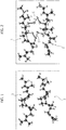
- FIGs 1 and 2 are schematic views showing some polymeric chains 1, 2 of a component made of an elastomeric material.
- the chains 1, 2 are illustrated in a state in which the rubber vulcanization method has not yet taken place.
- vulcanization creates a modification of the molecular conformation of the polymer, causing an increase in elasticity and tensile strength, and the suppression of negative properties such as abrasiveness.
- vulcanization is carried out using the elastomer in question, a source of sulfur and various additives; the combination of these products constitutes the compound. Pressure and temperature conditions may vary depending on the specific process involved.
- the polymeric chains 1, 2 undergo a reaction that creates chemical bonds C between the different chains 1, 2 ( Figure 2 ). By forming these bonds C, the physical properties of the component vary according to the relative quantity of these bonds.
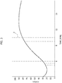
- Figure 3 illustrates an example of a rheometric curve of an elastomeric material that indicates the progress of the cross-linking state of the material during its hot-forming process.
- the time of the forming process is indicated on the horizontal axis
- an operational parameter of a measuring instrument is indicated on the vertical axis. From the curve it is possible to identify the value of t90 (indicated with the reference 3), which indicates the time of the forming process in which 90% of the cross-linking process has occurred.
- the component is removed from the mold and allowed to cool to complete the cross-linking process, until the component is completely cooled.
- the method according to the invention aimed at measuring the cross-linking degree of a component of elastomeric material, comprises a preliminary calibration step.
- the elastomeric material must be at least partially electrically-conductive.
- the elastomers used in the method of the invention must contain black carbon particles.
- the preliminary calibration step comprises providing a plurality of samples 8 of the same material as component C of which the cross-linking degree is to be measured.
- the samples 8 have identical dimensions (thickness, width and length). Taking as reference the rheometric curve of the material on which the measurement is to be carried out, the aforesaid samples 8 are obtained with different degrees of cross-linking following respective hot-forming processes conducted for different periods of time.
- the samples 8 are plate-shaped and are obtained following a process of extrusion or hot molding.
- the plate shape is to be considered purely by way of example, since the samples can be made with other shapes and sizes suitable for achieving the preset purposes (for example, of tubular shape).
- the preliminary calibration comprises providing a measuring device comprising an electrical circuit I in which a voltage generator 5 is arranged, along with metal contacts 7 configured to selectively receive one of the samples, and an ammeter 6.
- a measuring device comprising an electrical circuit I in which a voltage generator 5 is arranged, along with metal contacts 7 configured to selectively receive one of the samples, and an ammeter 6.
- these components are arranged in series with each other.
- one of the samples 8 is positioned between the metal contacts 7.
- the sample 8 must be positioned so it is not subject to stresses, for example, bending.
- the metal contacts 7 are made of copper and have a hood-like shape to receive the ends of the plate-shaped sample 8.
- the calibration step further comprises the following steps:
- the measurement of the corresponding current value by means of the ammeter 6 is performed consecutively at least three times, so as to have a statistical evaluation of the phenomenon.
- the predetermined voltage value applied is comprised between 1 V and 20 V, and is supplied by the generator 5 for a time of at least (60 ⁇ 1) seconds.
- the step of leaving the sample again in the resting configuration at room temperature following the measurement of the current value is continued for a time of at least (300 ⁇ 1) seconds.
- the samples 8 can be left in the resting condition by positioning them on the metal contacts 7 arranged in the electrical circuit II.
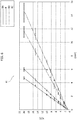
- a calibration map M illustrated in Figure 6 , which associates a given cross-linking degree of the material of which each sample 8 is made with each determined value of electrical conductivity.
- the example illustrated in Figure 6 includes three straight lines 8A, 8B and 8C, identifying different measurements made on three different samples 8 of the same material, obtained with different degrees of cross-linking interrupting the molding process at different times, respectively t1 ⁇ t2 ⁇ t3.
- the calibration map of Figure 6 shows the voltage value supplied by the voltage generator on the y-axis, and the corresponding determined electrical conductivity value on the x-axis.
- the line 8A identifying the sample with a lower cross-linking degree corresponding to the lower forming time t1 has lower electrical conductivity values than the samples identified with the straight lines 8B and 8C.
- the method includes a measuring step carried out directly on the component C of elastomeric material, whose degree of cross-linking is to be verified.
- This step of the method envisages measuring the electrical conductivity of the component C made of the same material as the samples 8, of which information must be obtained concerning the quality of its forming method.
- the measurement is carried out following the application of different voltage values, so as to obtain a straight line R on the calibration map M identifying the electrical conductivity of the component C.
- the method according to the invention therefore comprises a step of comparing the conductivity value of the samples 8 and of the component C, to obtain information on the quality of the component C on the basis of the aforesaid comparison.
- the straight line 8C identifies the acceptability margin
- the identifying straight line R of the electrical conductivity of the real component C provides information on the cross-linking degree of the component C.
- the quality of the forming process of the component C is lower than a minimum acceptable value. Consequently, again with reference to the specific case of the drawings, it is possible to proceed with the discarding of component C, since it was produced with a forming method carried out in incorrect conditions (linked, for example, to incorrect temperature, pressure or duration values of the process), thus avoiding installation of a defective component on the vehicle.
- the invention is also directed to an apparatus A (schematically illustrated in Figure 7 ), for quality control of a component C of elastomeric material obtained by a hot-forming process, comprising:
- the method and the relative apparatus allow a series of important advantages to be achieved.
- the measuring method is repeatable and reliable.
- the method according to the invention is adaptable to elastomeric components with different compositions and sizes.
- the method according to the invention is simple to implement and inexpensive.
Landscapes
- Chemical & Material Sciences (AREA)
- Health & Medical Sciences (AREA)
- Physics & Mathematics (AREA)
- Life Sciences & Earth Sciences (AREA)
- General Health & Medical Sciences (AREA)
- General Physics & Mathematics (AREA)
- Pathology (AREA)
- Immunology (AREA)
- Analytical Chemistry (AREA)
- Biochemistry (AREA)
- Engineering & Computer Science (AREA)
- Electrochemistry (AREA)
- Chemical Kinetics & Catalysis (AREA)
- Mechanical Engineering (AREA)
- Food Science & Technology (AREA)
- Medicinal Chemistry (AREA)
- Oral & Maxillofacial Surgery (AREA)
- Thermal Sciences (AREA)
- Investigating Or Analyzing Materials By The Use Of Electric Means (AREA)
- Measurement Of Resistance Or Impedance (AREA)
Abstract
Description
- The present invention relates to a method for measuring the cross-linking degree of a component of at least partially electrically-conductive elastomeric material, obtained as a result of a hot-forming process.
- The present invention also relates to an apparatus for the quality control of a component of at least partially electrically-conductive elastomeric material, obtained by a hot-forming process.
- The present invention is applied to components of elastomeric material mounted on board a motor-vehicle.
- The expression "cross-linking of an elastomeric material" means a process by which the polymeric chains of the material undergo a reaction which creates chemical bonds between different chains. With the formation of these bonds, the physical properties of the material vary according to the quantity and type of these bonds. The cross-linking process of rubber is commonly called the vulcanization process.
- Methods for measuring the cross-linking state of an elastomeric material have already been proposed in the past, of the type in which the measurement is carried out by means of systems configured to correlate the cross-linking state with the mechanical properties of the material (for example hardness, load and elongation at break, "compression set"). These known methods can have some disadvantages, such as high implementation times and costs, and margins of uncertainty on the results obtained.
- Moreover, in some cases, measuring the degree of cross-linking of the components may be unfeasible by the known methods, since the dimensions of these components are incompatible with the dimensions required to carry out the measurement by means of mechanical tests such as, for example, the load and elongation at break.
- To date, elastomeric materials are the basis for producing various components present on board motor-vehicles, for example, tubular components, gaskets, suspension components, tires, etc.
- In view of the above, there is a particular need to measure the degree of cross-linking of the materials constituting these components, in order to be able to carry out an in-depth analysis and identify possible problems in their production process, so as to avoid the use of defective components that could cause malfunctions during operation.
- The present invention is based on the need to propose a method for measuring the degree of cross-linking of a component made of elastomeric material, which is reliable and simple to implement.
- The object underlying the present invention is to provide a method of the type indicated at the beginning of the present description, and a relative apparatus, which overcomes the aforementioned drawbacks of the prior art, so as to provide a repeatable method, which leads to reliable results, and adaptable to elastomeric components with different compositions and sizes.
- A further object of the invention is that of achieving the aforesaid objective with a simple method to implement that is inexpensive.
- In order to achieve the aforesaid objects, the invention relates to a method having all the characteristics indicated at the beginning of the present description, comprising the following steps:
- performing a preliminary calibration step comprising:
- providing a plurality of samples made of the same material of said component, wherein said samples are obtained with different degrees of cross-linking following respective hot-forming processes conducted for different periods of time;
- leaving said samples in a resting condition at room temperature;
- providing a measuring device comprising an electrical circuit, in which a voltage generator is arranged in series with metal contacts configured to selectively receive a sample and an ammeter;
- positioning a sample between said metal contacts, avoiding that said sample is subject to bending,
- providing a predetermined voltage value by means of said voltage generator;
- detecting the corresponding current value by means of said ammeter;
- leaving the sample again in a resting configuration at room temperature;
- repeating the aforesaid steps of positioning the sample between the metal contacts, providing a voltage value and detecting the corresponding current value, in which the voltage value generated by said voltage generator is different with respect to the previously applied voltage value;
- repeating the aforesaid steps for each sample, so as to obtain a calibration map that associates a given degree of cross-linking of the material constituting said component with each determined value of electrical conductivity;
- performing a step of measuring the electrical conductivity of said component, to compare said conductivity value with a predetermined threshold value obtained from said calibration map and obtaining information on the quality of the component based on the aforesaid comparison.
- Preferably, during said preliminary calibration step, for each voltage value applied on each sample, measuring the corresponding current value by means of said ammeter is performed consecutively at least three times, so as to have a statistical evaluation of the phenomenon.
- Preferably, said predetermined voltage value is between 1 V and 20 V, and is provided by said voltage generator for at least (60±1) seconds.
- Preferably, the step of leaving the sample again in the resting configuration at room temperature following the measurement of the current value is continued for a time of at least (300±1) seconds.
- The present invention also relates to an apparatus for quality control of a component of at least partially electrically-conductive elastomeric material, obtained by a hot-forming process, comprising:
- an electrical circuit to measure the electrical conductivity of the component, and
- an electronic controller associated with a memory containing a calibration map that associates a given degree of cross-linking of the material constituting said component with each determined value of electrical conductivity,
- said electronic controller being programmed to receive information on the electrical conductivity value of the component from said electronic circuit, to compare said conductivity value with a predetermined threshold value and provide information on the quality of the component on the basis of the aforesaid comparison.
- Further characteristics and advantages of the invention will become apparent from the following description, provided purely by way of nonlimiting example, with reference to a preferred embodiment of the invention.
- Embodiments of the invention are illustrated in the attached drawings, wherein:
-
Figures 1 and 2 illustrate schematic views of chemical bonds between the polymeric chains of an elastomeric material, before and after a vulcanization process, respectively, -
Figure 3 is a graph indicating the correlation between the degree of cross-linking of an elastomeric material and the forming process to which it is subjected, -
Figures 4 and 5 are schematic views that illustrate some steps of the method according to the invention, -
Figure 6 is a calibration map obtained following a step of the method according to the invention, and -
Figure 7 illustrates a schematic perspective view of a measuring apparatus. - In the following description, various specific details are illustrated aimed at a thorough understanding of examples of one or more embodiments. The embodiments can be implemented without one or more of the specific details, or with other methods, components, materials, etc. In other cases, known structures, materials, or operations are not shown or described in detail to avoid obscuring various aspects of the embodiments.
- The reference to "an embodiment" in the context of this description indicates that a particular configuration, structure or characteristic described in relation to the embodiment is included in at least one embodiment. Therefore, phrases such as "in an embodiment", possibly present in different places of this description do not necessarily refer to the same embodiment. Moreover, particular conformations, structures or characteristics can be combined in a suitable manner in one or more embodiments and/or associated with the embodiments in a different way from that illustrated here, for example, a characteristic here exemplified in relation to a figure may be applied to one or more embodiments exemplified in a different figure.
- The references illustrated here are only for convenience and do not, therefore, delimit the field of protection or the scope of the embodiments.
-
Figures 1 and 2 are schematic views showing somepolymeric chains Figure 1 , thechains - Following this process, the
polymeric chains different chains 1, 2 (Figure 2 ). By forming these bonds C, the physical properties of the component vary according to the relative quantity of these bonds. -
Figure 3 illustrates an example of a rheometric curve of an elastomeric material that indicates the progress of the cross-linking state of the material during its hot-forming process. In this figure, the time of the forming process is indicated on the horizontal axis, and an operational parameter of a measuring instrument (rheometer) is indicated on the vertical axis. From the curve it is possible to identify the value of t90 (indicated with the reference 3), which indicates the time of the forming process in which 90% of the cross-linking process has occurred. Typically, in a hot-forming method of an elastomeric material, in particular in the extrusion or molding process, when the time of the forming method reaches the value of t90, the component is removed from the mold and allowed to cool to complete the cross-linking process, until the component is completely cooled. - According to the illustrated example, the method according to the invention, aimed at measuring the cross-linking degree of a component of elastomeric material, comprises a preliminary calibration step. In order to make the method feasible, the elastomeric material must be at least partially electrically-conductive. For this reason, the elastomers used in the method of the invention must contain black carbon particles.
- The preliminary calibration step comprises providing a plurality of
samples 8 of the same material as component C of which the cross-linking degree is to be measured. Thesamples 8 have identical dimensions (thickness, width and length). Taking as reference the rheometric curve of the material on which the measurement is to be carried out, theaforesaid samples 8 are obtained with different degrees of cross-linking following respective hot-forming processes conducted for different periods of time. - Preferably, the
samples 8 are plate-shaped and are obtained following a process of extrusion or hot molding. Of course, the plate shape is to be considered purely by way of example, since the samples can be made with other shapes and sizes suitable for achieving the preset purposes (for example, of tubular shape). - In various embodiments, as in the one illustrated, the preliminary calibration comprises providing a measuring device comprising an electrical circuit I in which a
voltage generator 5 is arranged, along withmetal contacts 7 configured to selectively receive one of the samples, and anammeter 6. Preferably, these components are arranged in series with each other. - Following a step in which the
samples 8 are left in a resting condition at room temperature, after their hot-forming, one of thesamples 8 is positioned between themetal contacts 7. Thesample 8 must be positioned so it is not subject to stresses, for example, bending. - In a concrete embodiment, the
metal contacts 7 are made of copper and have a hood-like shape to receive the ends of the plate-shapedsample 8. - In various embodiments, as in the illustrated one, the calibration step further comprises the following steps:
- providing a predetermined voltage value by means of the
voltage generator 5; - detecting the corresponding current value by means of the
ammeter 6, corresponding to the conductivity value of thesample 8, - leaving the
sample 8 again in a resting configuration at room temperature, - repeating the steps of positioning the sample between the
metal contacts 7, providing a voltage value and detecting the corresponding current value, in which the voltage value generated by thevoltage generator 5 is different with respect to the previously applied voltage value. - Preferably, for each voltage value applied, the measurement of the corresponding current value by means of the
ammeter 6 is performed consecutively at least three times, so as to have a statistical evaluation of the phenomenon. - Still according to a further preferred characteristic of the invention, the predetermined voltage value applied is comprised between 1 V and 20 V, and is supplied by the
generator 5 for a time of at least (60±1) seconds. - Still according to a preferred characteristic of the invention, the step of leaving the sample again in the resting configuration at room temperature following the measurement of the current value is continued for a time of at least (300±1) seconds.
- As illustrated in
Figure 5 , thesamples 8 can be left in the resting condition by positioning them on themetal contacts 7 arranged in the electrical circuit II. - By repeating the aforesaid preliminary calibration steps for each
sample 8, it is possible to obtain a calibration map M, illustrated inFigure 6 , which associates a given cross-linking degree of the material of which eachsample 8 is made with each determined value of electrical conductivity. The example illustrated inFigure 6 includes threestraight lines 8A, 8B and 8C, identifying different measurements made on threedifferent samples 8 of the same material, obtained with different degrees of cross-linking interrupting the molding process at different times, respectively t1 < t2 <t3. - More specifically, the calibration map of
Figure 6 shows the voltage value supplied by the voltage generator on the y-axis, and the corresponding determined electrical conductivity value on the x-axis. Theline 8A identifying the sample with a lower cross-linking degree corresponding to the lower forming time t1 has lower electrical conductivity values than the samples identified with the straight lines 8B and 8C. - According to the method according to the invention, following the preliminary calibration step indicated above, which leads to defining of the calibration map M for a specific type of elastomeric material (for example, illustrated in
Figure 6 ), the method includes a measuring step carried out directly on the component C of elastomeric material, whose degree of cross-linking is to be verified. This step of the method envisages measuring the electrical conductivity of the component C made of the same material as thesamples 8, of which information must be obtained concerning the quality of its forming method. - The measurement is carried out following the application of different voltage values, so as to obtain a straight line R on the calibration map M identifying the electrical conductivity of the component C.
- The method according to the invention therefore comprises a step of comparing the conductivity value of the
samples 8 and of the component C, to obtain information on the quality of the component C on the basis of the aforesaid comparison. - In the example shown in
Figure 6 , assuming that the straight line 8C identifies the acceptability margin, the identifying straight line R of the electrical conductivity of the real component C, provides information on the cross-linking degree of the component C. In this case, the quality of the forming process of the component C is lower than a minimum acceptable value. Consequently, again with reference to the specific case of the drawings, it is possible to proceed with the discarding of component C, since it was produced with a forming method carried out in incorrect conditions (linked, for example, to incorrect temperature, pressure or duration values of the process), thus avoiding installation of a defective component on the vehicle. - As already indicated, the invention is also directed to an apparatus A (schematically illustrated in
Figure 7 ), for quality control of a component C of elastomeric material obtained by a hot-forming process, comprising: - an electrical circuit to measure the electrical conductivity of the component C, and
- an electronic controller associated with a memory containing a calibration map that associates a given degree of cross-linking of the material constituting component C with each determined electrical conductivity value. The electronic controller is programmed to receive information on the value of electrical conductivity of the component C from the electronic circuit, to compare said conductivity value with a predetermined threshold value, and provide information on the quality of the component based on the aforesaid comparison. In this way, it is possible to obtain information on the quality of the production method of the component C, thus avoiding the mounting of a component on motor-vehicles that does not comply with the required requirements, which could lead to malfunctions during operation.
- Thanks to the characteristics indicated above, the method and the relative apparatus allow a series of important advantages to be achieved. First of all, the measuring method is repeatable and reliable. Secondly, the method according to the invention is adaptable to elastomeric components with different compositions and sizes. Moreover, the method according to the invention is simple to implement and inexpensive.
- Of course, without prejudice to the principle of the invention, the details of construction and the embodiments may vary widely with respect to those described and illustrated purely by way of example, without departing from the scope of the present invention.
Claims (9)
- A method for measuring the cross-linking degree of a component (C) of at least partially electrically-conductive elastomeric material, obtained as a result of a hot-forming process, comprising the following steps:- performing a preliminary calibration step comprising:- providing a plurality of samples (8) made of the same material of said component (C), wherein said samples (8) are obtained with different degrees of cross-linking following respective hot-forming processes conducted for different periods of time;- leaving said samples in a resting condition at room temperature;- providing a measuring device comprising an electrical circuit (I), in which a voltage generator (5) is arranged in series with metal contacts (7) configured to selectively receive a sample (8), and an ammeter (6);- positioning a sample (8) between said metal contacts (7), so that said sample (8) is not subject to bending,- providing a predetermined voltage value by means of said voltage generator (5);- detecting the corresponding current value by means of said ammeter (6);- leaving the sample (8) again in a resting configuration at room temperature;- repeating the aforesaid steps of positioning the sample between the metal contacts (7), providing a voltage value and detecting the corresponding current value, in which the voltage value generated by said voltage generator (5) is different with respect to the previously applied voltage value;- repeating the aforementioned steps for each sample (8), so as to obtain a calibration map (M) that associates a given degree of cross-linking of the material constituting said component (C) with each determined value of electrical conductivity;- performing a step of measuring the electrical conductivity of said component (C), to compare said conductivity value with a predetermined threshold value obtained from said calibration map (M) and obtaining information on the quality of the component (C) based on the aforesaid comparison.
- A method according to claim 1, characterized in that during said preliminary calibration step, for each voltage value applied on each sample (8), measuring the corresponding current value by means of said ammeter (6) is performed consecutively at least three times, so as to have a statistical evaluation of the phenomenon.
- A method according to claim 1, characterized in that said hot-forming processes include an extrusion or molding process.
- A method according to claim 1, characterized in that said samples (8) are homogeneous in terms of size and production process.
- A method according to claim 4, characterized in that said samples (8) are shaped like a plate.
- A method according to claim 1, characterized in that said predetermined voltage value is between 1 V and 20 V, and is provided by said voltage generator (5) for at least (60±1) seconds.
- A method according to claim 1, characterized in that the step of leaving said samples (8) in a resting condition at room temperature following the forming process is continued for a time of at least 24 hours.
- A method according to claim 1, characterized in that the step of leaving the sample (8) again in the resting configuration at room temperature following the measurement of the current value is continued for a time of at least (300±1) seconds.
- An apparatus (A) for the quality control of a component (C) of at least partially electrically-conductive elastomeric material, obtained by a hot-forming process, comprising:- an electrical circuit to measure the electrical conductivity of the component (C), and- an electronic controller associated with a memory containing a calibration map (M) that associates a given degree of cross-linking of the material constituting said component (C) with each determined value of electrical conductivity,- said electronic controller being programmed to receive information on the electrical conductivity value of the component (C) from said electronic circuit, to compare said conductivity value with a predetermined threshold value and provide information on the quality of the component (C) on the basis of the aforesaid comparison.
Priority Applications (4)
| Application Number | Priority Date | Filing Date | Title |
|---|---|---|---|
| EP19214709.8A EP3835771B1 (en) | 2019-12-10 | 2019-12-10 | Method for measuring the cross-linking degree of a component of elastomeric material |
| PCT/IB2020/057508 WO2021116784A1 (en) | 2019-12-10 | 2020-08-10 | A method for measuring the cross-linking degree of a component of elastomeric material |
| CN202080040530.2A CN113939738A (en) | 2019-12-10 | 2020-08-10 | Method for measuring the degree of crosslinking of a component of elastomeric material |
| US17/595,743 US12370735B2 (en) | 2019-12-10 | 2020-08-10 | Method for use in measuring a property of an automobile component |
Applications Claiming Priority (1)
| Application Number | Priority Date | Filing Date | Title |
|---|---|---|---|
| EP19214709.8A EP3835771B1 (en) | 2019-12-10 | 2019-12-10 | Method for measuring the cross-linking degree of a component of elastomeric material |
Publications (2)
| Publication Number | Publication Date |
|---|---|
| EP3835771A1 true EP3835771A1 (en) | 2021-06-16 |
| EP3835771B1 EP3835771B1 (en) | 2022-08-10 |
Family
ID=69191845
Family Applications (1)
| Application Number | Title | Priority Date | Filing Date |
|---|---|---|---|
| EP19214709.8A Active EP3835771B1 (en) | 2019-12-10 | 2019-12-10 | Method for measuring the cross-linking degree of a component of elastomeric material |
Country Status (4)
| Country | Link |
|---|---|
| US (1) | US12370735B2 (en) |
| EP (1) | EP3835771B1 (en) |
| CN (1) | CN113939738A (en) |
| WO (1) | WO2021116784A1 (en) |
Families Citing this family (2)
| Publication number | Priority date | Publication date | Assignee | Title |
|---|---|---|---|---|
| EP4167065B1 (en) * | 2021-08-25 | 2026-01-28 | Seoul National University R&DB Foundation | Triboresistive touch sensor |
| CN116698640A (en) * | 2023-07-14 | 2023-09-05 | 英利能源发展有限公司 | Environment-friendly crosslinking degree testing method |
Citations (4)
| Publication number | Priority date | Publication date | Assignee | Title |
|---|---|---|---|---|
| JPH02275349A (en) * | 1989-04-15 | 1990-11-09 | Nok Corp | Evaluating method for vulcanization bonding |
| US20050119785A1 (en) * | 2001-03-21 | 2005-06-02 | Signature Control Systems | Process and apparatus for improving and controlling the vulcanization of natural and synthetic rubber compounds |
| US8217669B1 (en) * | 2007-08-22 | 2012-07-10 | Watkins Jr Kenneth S | Electrical sensor for monitoring degradation of products from environmental stressors |
| EP2500718A2 (en) * | 2011-03-14 | 2012-09-19 | ContiTech AG | Method for measuring the change in conductivity of a visco-elastic material during its production by combining rheological and dielectric testing methods |
Family Cites Families (5)
| Publication number | Priority date | Publication date | Assignee | Title |
|---|---|---|---|---|
| US6774643B2 (en) * | 2001-03-21 | 2004-08-10 | Signature Control Systems | Non-bridged single electrode impedance measurement system for determining a condition of a dielectric according to impedance related changes over a range of frequencies |
| ITTO20010389A1 (en) * | 2001-04-20 | 2002-10-20 | Bridgestone Firestone Tech | PLANT AND METHOD FOR THE PRODUCTION OF PMEUMATICS WITH IN-LINE CONTROL OF ELECTRIC CONDUCTIVITY. |
| EP2499175B2 (en) * | 2009-11-11 | 2022-08-17 | Borealis AG | A polymer composition and a power cable comprising the polymer composition |
| ES2966769T3 (en) * | 2017-09-26 | 2024-04-24 | Hoffmann La Roche | Calibration procedure |
| EP3672067B1 (en) | 2018-12-20 | 2021-07-28 | Commissariat à l'énergie atomique et aux énergies alternatives | Method for characterizing the average crosslinking rate of an encapsulation layer in a photovoltaic module |
-
2019
- 2019-12-10 EP EP19214709.8A patent/EP3835771B1/en active Active
-
2020
- 2020-08-10 WO PCT/IB2020/057508 patent/WO2021116784A1/en not_active Ceased
- 2020-08-10 CN CN202080040530.2A patent/CN113939738A/en active Pending
- 2020-08-10 US US17/595,743 patent/US12370735B2/en active Active
Patent Citations (4)
| Publication number | Priority date | Publication date | Assignee | Title |
|---|---|---|---|---|
| JPH02275349A (en) * | 1989-04-15 | 1990-11-09 | Nok Corp | Evaluating method for vulcanization bonding |
| US20050119785A1 (en) * | 2001-03-21 | 2005-06-02 | Signature Control Systems | Process and apparatus for improving and controlling the vulcanization of natural and synthetic rubber compounds |
| US8217669B1 (en) * | 2007-08-22 | 2012-07-10 | Watkins Jr Kenneth S | Electrical sensor for monitoring degradation of products from environmental stressors |
| EP2500718A2 (en) * | 2011-03-14 | 2012-09-19 | ContiTech AG | Method for measuring the change in conductivity of a visco-elastic material during its production by combining rheological and dielectric testing methods |
Also Published As
| Publication number | Publication date |
|---|---|
| WO2021116784A1 (en) | 2021-06-17 |
| US20220314519A1 (en) | 2022-10-06 |
| CN113939738A (en) | 2022-01-14 |
| US12370735B2 (en) | 2025-07-29 |
| EP3835771B1 (en) | 2022-08-10 |
Similar Documents
| Publication | Publication Date | Title |
|---|---|---|
| Stone et al. | The application of Weibull statistics to insulation aging tests | |
| US12370735B2 (en) | Method for use in measuring a property of an automobile component | |
| CN105842598A (en) | Cross-linked polyethylene cable life detection method | |
| CN113219311B (en) | Test method for rapidly evaluating corona resistance time of enameled wire | |
| US6924652B2 (en) | Method for determining optimal degree of vulcanization and optimal content of constituent ingredient of composition for vulcanization in real time by impedance measurement and analysis | |
| CN115327267B (en) | A high and low temperature cycle test method, system, terminal and storage medium | |
| CN113884264B (en) | Composite vibration and impact test method of thin film capacitor for electric automobile | |
| Muhonen et al. | HMM round robin study: What to expect when testing components to the IEC 61000-4-2 waveform | |
| CN112834943A (en) | Battery management system life test method and device based on high temperature endurance test | |
| CN106291380A (en) | The appraisal procedure of cell degradation and device | |
| CN117129812A (en) | A testing method and evaluation system for space charge performance of DC cable insulation materials | |
| CN110851936A (en) | Through hole welding spot reliability evaluation test method and device | |
| KR20150004446A (en) | Wire harness inspection method | |
| CN118758839A (en) | A method for testing accelerated thermal oxidation aging of thermoplastic cable insulation materials | |
| JP2020085776A (en) | Rubber inspection method | |
| CN116735389A (en) | Method to obtain elastic-plastic fatigue crack growth rate based on low-cycle fatigue test | |
| EP4624965A1 (en) | An automated process for testing a wire harness | |
| Tanış et al. | A comparative case study for fatigue lifetime predictors on EPDM rubber | |
| EP4624947A1 (en) | A wire harness automated diagnosis system and method | |
| del Casale et al. | Direct interaction between partial discharge and temperature on epoxies: phenomenological life models | |
| JP5867191B2 (en) | Evaluation method of spring material for connector terminals | |
| EP4624946A1 (en) | A wire harness automated diagnosis system and method | |
| JP2020085777A (en) | Rubber inspection method | |
| CN117761441A (en) | A multi-factor combined aging test device and method for silicone rubber materials | |
| CN118501628A (en) | Method for testing performance of lead |
Legal Events
| Date | Code | Title | Description |
|---|---|---|---|
| STAA | Information on the status of an ep patent application or granted ep patent |
Free format text: STATUS: EXAMINATION IS IN PROGRESS |
|
| PUAI | Public reference made under article 153(3) epc to a published international application that has entered the european phase |
Free format text: ORIGINAL CODE: 0009012 |
|
| 17P | Request for examination filed |
Effective date: 20201013 |
|
| AK | Designated contracting states |
Kind code of ref document: A1 Designated state(s): AL AT BE BG CH CY CZ DE DK EE ES FI FR GB GR HR HU IE IS IT LI LT LU LV MC MK MT NL NO PL PT RO RS SE SI SK SM TR |
|
| GRAP | Despatch of communication of intention to grant a patent |
Free format text: ORIGINAL CODE: EPIDOSNIGR1 |
|
| STAA | Information on the status of an ep patent application or granted ep patent |
Free format text: STATUS: GRANT OF PATENT IS INTENDED |
|
| INTG | Intention to grant announced |
Effective date: 20220404 |
|
| GRAS | Grant fee paid |
Free format text: ORIGINAL CODE: EPIDOSNIGR3 |
|
| GRAA | (expected) grant |
Free format text: ORIGINAL CODE: 0009210 |
|
| STAA | Information on the status of an ep patent application or granted ep patent |
Free format text: STATUS: THE PATENT HAS BEEN GRANTED |
|
| AK | Designated contracting states |
Kind code of ref document: B1 Designated state(s): AL AT BE BG CH CY CZ DE DK EE ES FI FR GB GR HR HU IE IS IT LI LT LU LV MC MK MT NL NO PL PT RO RS SE SI SK SM TR |
|
| REG | Reference to a national code |
Ref country code: AT Ref legal event code: REF Ref document number: 1510914 Country of ref document: AT Kind code of ref document: T Effective date: 20220815 Ref country code: CH Ref legal event code: EP |
|
| REG | Reference to a national code |
Ref country code: IE Ref legal event code: FG4D |
|
| REG | Reference to a national code |
Ref country code: DE Ref legal event code: R096 Ref document number: 602019018063 Country of ref document: DE |
|
| REG | Reference to a national code |
Ref country code: NL Ref legal event code: MP Effective date: 20220810 |
|
| REG | Reference to a national code |
Ref country code: LT Ref legal event code: MG9D |
|
| PG25 | Lapsed in a contracting state [announced via postgrant information from national office to epo] |
Ref country code: SE Free format text: LAPSE BECAUSE OF FAILURE TO SUBMIT A TRANSLATION OF THE DESCRIPTION OR TO PAY THE FEE WITHIN THE PRESCRIBED TIME-LIMIT Effective date: 20220810 Ref country code: RS Free format text: LAPSE BECAUSE OF FAILURE TO SUBMIT A TRANSLATION OF THE DESCRIPTION OR TO PAY THE FEE WITHIN THE PRESCRIBED TIME-LIMIT Effective date: 20220810 Ref country code: PT Free format text: LAPSE BECAUSE OF FAILURE TO SUBMIT A TRANSLATION OF THE DESCRIPTION OR TO PAY THE FEE WITHIN THE PRESCRIBED TIME-LIMIT Effective date: 20221212 Ref country code: NO Free format text: LAPSE BECAUSE OF FAILURE TO SUBMIT A TRANSLATION OF THE DESCRIPTION OR TO PAY THE FEE WITHIN THE PRESCRIBED TIME-LIMIT Effective date: 20221110 Ref country code: NL Free format text: LAPSE BECAUSE OF FAILURE TO SUBMIT A TRANSLATION OF THE DESCRIPTION OR TO PAY THE FEE WITHIN THE PRESCRIBED TIME-LIMIT Effective date: 20220810 Ref country code: LV Free format text: LAPSE BECAUSE OF FAILURE TO SUBMIT A TRANSLATION OF THE DESCRIPTION OR TO PAY THE FEE WITHIN THE PRESCRIBED TIME-LIMIT Effective date: 20220810 Ref country code: LT Free format text: LAPSE BECAUSE OF FAILURE TO SUBMIT A TRANSLATION OF THE DESCRIPTION OR TO PAY THE FEE WITHIN THE PRESCRIBED TIME-LIMIT Effective date: 20220810 Ref country code: FI Free format text: LAPSE BECAUSE OF FAILURE TO SUBMIT A TRANSLATION OF THE DESCRIPTION OR TO PAY THE FEE WITHIN THE PRESCRIBED TIME-LIMIT Effective date: 20220810 |
|
| REG | Reference to a national code |
Ref country code: AT Ref legal event code: MK05 Ref document number: 1510914 Country of ref document: AT Kind code of ref document: T Effective date: 20220810 |
|
| PG25 | Lapsed in a contracting state [announced via postgrant information from national office to epo] |
Ref country code: PL Free format text: LAPSE BECAUSE OF FAILURE TO SUBMIT A TRANSLATION OF THE DESCRIPTION OR TO PAY THE FEE WITHIN THE PRESCRIBED TIME-LIMIT Effective date: 20220810 Ref country code: IS Free format text: LAPSE BECAUSE OF FAILURE TO SUBMIT A TRANSLATION OF THE DESCRIPTION OR TO PAY THE FEE WITHIN THE PRESCRIBED TIME-LIMIT Effective date: 20221210 Ref country code: HR Free format text: LAPSE BECAUSE OF FAILURE TO SUBMIT A TRANSLATION OF THE DESCRIPTION OR TO PAY THE FEE WITHIN THE PRESCRIBED TIME-LIMIT Effective date: 20220810 Ref country code: GR Free format text: LAPSE BECAUSE OF FAILURE TO SUBMIT A TRANSLATION OF THE DESCRIPTION OR TO PAY THE FEE WITHIN THE PRESCRIBED TIME-LIMIT Effective date: 20221111 |
|
| PG25 | Lapsed in a contracting state [announced via postgrant information from national office to epo] |
Ref country code: SM Free format text: LAPSE BECAUSE OF FAILURE TO SUBMIT A TRANSLATION OF THE DESCRIPTION OR TO PAY THE FEE WITHIN THE PRESCRIBED TIME-LIMIT Effective date: 20220810 Ref country code: RO Free format text: LAPSE BECAUSE OF FAILURE TO SUBMIT A TRANSLATION OF THE DESCRIPTION OR TO PAY THE FEE WITHIN THE PRESCRIBED TIME-LIMIT Effective date: 20220810 Ref country code: ES Free format text: LAPSE BECAUSE OF FAILURE TO SUBMIT A TRANSLATION OF THE DESCRIPTION OR TO PAY THE FEE WITHIN THE PRESCRIBED TIME-LIMIT Effective date: 20220810 Ref country code: DK Free format text: LAPSE BECAUSE OF FAILURE TO SUBMIT A TRANSLATION OF THE DESCRIPTION OR TO PAY THE FEE WITHIN THE PRESCRIBED TIME-LIMIT Effective date: 20220810 Ref country code: CZ Free format text: LAPSE BECAUSE OF FAILURE TO SUBMIT A TRANSLATION OF THE DESCRIPTION OR TO PAY THE FEE WITHIN THE PRESCRIBED TIME-LIMIT Effective date: 20220810 Ref country code: AT Free format text: LAPSE BECAUSE OF FAILURE TO SUBMIT A TRANSLATION OF THE DESCRIPTION OR TO PAY THE FEE WITHIN THE PRESCRIBED TIME-LIMIT Effective date: 20220810 |
|
| REG | Reference to a national code |
Ref country code: DE Ref legal event code: R097 Ref document number: 602019018063 Country of ref document: DE |
|
| PG25 | Lapsed in a contracting state [announced via postgrant information from national office to epo] |
Ref country code: SK Free format text: LAPSE BECAUSE OF FAILURE TO SUBMIT A TRANSLATION OF THE DESCRIPTION OR TO PAY THE FEE WITHIN THE PRESCRIBED TIME-LIMIT Effective date: 20220810 Ref country code: EE Free format text: LAPSE BECAUSE OF FAILURE TO SUBMIT A TRANSLATION OF THE DESCRIPTION OR TO PAY THE FEE WITHIN THE PRESCRIBED TIME-LIMIT Effective date: 20220810 |
|
| PLBE | No opposition filed within time limit |
Free format text: ORIGINAL CODE: 0009261 |
|
| STAA | Information on the status of an ep patent application or granted ep patent |
Free format text: STATUS: NO OPPOSITION FILED WITHIN TIME LIMIT |
|
| PG25 | Lapsed in a contracting state [announced via postgrant information from national office to epo] |
Ref country code: AL Free format text: LAPSE BECAUSE OF FAILURE TO SUBMIT A TRANSLATION OF THE DESCRIPTION OR TO PAY THE FEE WITHIN THE PRESCRIBED TIME-LIMIT Effective date: 20220810 |
|
| 26N | No opposition filed |
Effective date: 20230511 |
|
| REG | Reference to a national code |
Ref country code: CH Ref legal event code: PL |
|
| REG | Reference to a national code |
Ref country code: BE Ref legal event code: MM Effective date: 20221231 |
|
| PG25 | Lapsed in a contracting state [announced via postgrant information from national office to epo] |
Ref country code: SI Free format text: LAPSE BECAUSE OF FAILURE TO SUBMIT A TRANSLATION OF THE DESCRIPTION OR TO PAY THE FEE WITHIN THE PRESCRIBED TIME-LIMIT Effective date: 20220810 Ref country code: LU Free format text: LAPSE BECAUSE OF NON-PAYMENT OF DUE FEES Effective date: 20221210 |
|
| PG25 | Lapsed in a contracting state [announced via postgrant information from national office to epo] |
Ref country code: LI Free format text: LAPSE BECAUSE OF NON-PAYMENT OF DUE FEES Effective date: 20221231 Ref country code: IE Free format text: LAPSE BECAUSE OF NON-PAYMENT OF DUE FEES Effective date: 20221210 Ref country code: CH Free format text: LAPSE BECAUSE OF NON-PAYMENT OF DUE FEES Effective date: 20221231 |
|
| PG25 | Lapsed in a contracting state [announced via postgrant information from national office to epo] |
Ref country code: BE Free format text: LAPSE BECAUSE OF NON-PAYMENT OF DUE FEES Effective date: 20221231 |
|
| PG25 | Lapsed in a contracting state [announced via postgrant information from national office to epo] |
Ref country code: CY Free format text: LAPSE BECAUSE OF FAILURE TO SUBMIT A TRANSLATION OF THE DESCRIPTION OR TO PAY THE FEE WITHIN THE PRESCRIBED TIME-LIMIT Effective date: 20220810 |
|
| PG25 | Lapsed in a contracting state [announced via postgrant information from national office to epo] |
Ref country code: MK Free format text: LAPSE BECAUSE OF FAILURE TO SUBMIT A TRANSLATION OF THE DESCRIPTION OR TO PAY THE FEE WITHIN THE PRESCRIBED TIME-LIMIT Effective date: 20220810 Ref country code: HU Free format text: LAPSE BECAUSE OF FAILURE TO SUBMIT A TRANSLATION OF THE DESCRIPTION OR TO PAY THE FEE WITHIN THE PRESCRIBED TIME-LIMIT; INVALID AB INITIO Effective date: 20191210 |
|
| PG25 | Lapsed in a contracting state [announced via postgrant information from national office to epo] |
Ref country code: MC Free format text: LAPSE BECAUSE OF FAILURE TO SUBMIT A TRANSLATION OF THE DESCRIPTION OR TO PAY THE FEE WITHIN THE PRESCRIBED TIME-LIMIT Effective date: 20220810 |
|
| PG25 | Lapsed in a contracting state [announced via postgrant information from national office to epo] |
Ref country code: TR Free format text: LAPSE BECAUSE OF FAILURE TO SUBMIT A TRANSLATION OF THE DESCRIPTION OR TO PAY THE FEE WITHIN THE PRESCRIBED TIME-LIMIT Effective date: 20220810 Ref country code: MC Free format text: LAPSE BECAUSE OF FAILURE TO SUBMIT A TRANSLATION OF THE DESCRIPTION OR TO PAY THE FEE WITHIN THE PRESCRIBED TIME-LIMIT Effective date: 20220810 |
|
| PG25 | Lapsed in a contracting state [announced via postgrant information from national office to epo] |
Ref country code: BG Free format text: LAPSE BECAUSE OF FAILURE TO SUBMIT A TRANSLATION OF THE DESCRIPTION OR TO PAY THE FEE WITHIN THE PRESCRIBED TIME-LIMIT Effective date: 20220810 |
|
| GBPC | Gb: european patent ceased through non-payment of renewal fee |
Effective date: 20231210 |
|
| PG25 | Lapsed in a contracting state [announced via postgrant information from national office to epo] |
Ref country code: MT Free format text: LAPSE BECAUSE OF FAILURE TO SUBMIT A TRANSLATION OF THE DESCRIPTION OR TO PAY THE FEE WITHIN THE PRESCRIBED TIME-LIMIT Effective date: 20220810 |
|
| PG25 | Lapsed in a contracting state [announced via postgrant information from national office to epo] |
Ref country code: GB Free format text: LAPSE BECAUSE OF NON-PAYMENT OF DUE FEES Effective date: 20231210 |
|
| PG25 | Lapsed in a contracting state [announced via postgrant information from national office to epo] |
Ref country code: GB Free format text: LAPSE BECAUSE OF NON-PAYMENT OF DUE FEES Effective date: 20231210 |
|
| PGFP | Annual fee paid to national office [announced via postgrant information from national office to epo] |
Ref country code: DE Payment date: 20251126 Year of fee payment: 7 |
|
| PGFP | Annual fee paid to national office [announced via postgrant information from national office to epo] |
Ref country code: IT Payment date: 20251119 Year of fee payment: 7 |
|
| PGFP | Annual fee paid to national office [announced via postgrant information from national office to epo] |
Ref country code: FR Payment date: 20251119 Year of fee payment: 7 |