EP3835756A1 - Particle detection device and method and method of manufacturing - Google Patents
Particle detection device and method and method of manufacturing Download PDFInfo
- Publication number
- EP3835756A1 EP3835756A1 EP20212687.6A EP20212687A EP3835756A1 EP 3835756 A1 EP3835756 A1 EP 3835756A1 EP 20212687 A EP20212687 A EP 20212687A EP 3835756 A1 EP3835756 A1 EP 3835756A1
- Authority
- EP
- European Patent Office
- Prior art keywords
- variation
- wavelengths
- particle
- incident radiation
- sub
- Prior art date
- Legal status (The legal status is an assumption and is not a legal conclusion. Google has not performed a legal analysis and makes no representation as to the accuracy of the status listed.)
- Granted
Links
- 239000002245 particle Substances 0.000 title claims abstract description 135
- 238000001514 detection method Methods 0.000 title claims abstract description 36
- 238000000034 method Methods 0.000 title claims description 31
- 238000004519 manufacturing process Methods 0.000 title claims description 11
- 230000005855 radiation Effects 0.000 claims abstract description 88
- 230000010363 phase shift Effects 0.000 claims abstract description 35
- 239000000758 substrate Substances 0.000 claims abstract description 25
- 239000011159 matrix material Substances 0.000 claims abstract description 11
- 230000003595 spectral effect Effects 0.000 claims description 62
- 238000010521 absorption reaction Methods 0.000 claims description 36
- 239000010409 thin film Substances 0.000 claims description 24
- 230000001427 coherent effect Effects 0.000 claims description 9
- GWEVSGVZZGPLCZ-UHFFFAOYSA-N Titan oxide Chemical compound O=[Ti]=O GWEVSGVZZGPLCZ-UHFFFAOYSA-N 0.000 claims description 8
- MCMNRKCIXSYSNV-UHFFFAOYSA-N Zirconium dioxide Chemical compound O=[Zr]=O MCMNRKCIXSYSNV-UHFFFAOYSA-N 0.000 claims description 8
- 238000005286 illumination Methods 0.000 claims description 7
- 238000013461 design Methods 0.000 claims description 6
- 239000000463 material Substances 0.000 claims description 6
- 230000001747 exhibiting effect Effects 0.000 claims description 5
- 229910004541 SiN Inorganic materials 0.000 claims description 4
- UHYPYGJEEGLRJD-UHFFFAOYSA-N cadmium(2+);selenium(2-) Chemical compound [Se-2].[Cd+2] UHYPYGJEEGLRJD-UHFFFAOYSA-N 0.000 claims description 4
- 230000001939 inductive effect Effects 0.000 claims description 4
- 238000012545 processing Methods 0.000 claims description 4
- SBIBMFFZSBJNJF-UHFFFAOYSA-N selenium;zinc Chemical compound [Se]=[Zn] SBIBMFFZSBJNJF-UHFFFAOYSA-N 0.000 claims description 4
- 229910052710 silicon Inorganic materials 0.000 claims description 4
- PBCFLUZVCVVTBY-UHFFFAOYSA-N tantalum pentoxide Inorganic materials O=[Ta](=O)O[Ta](=O)=O PBCFLUZVCVVTBY-UHFFFAOYSA-N 0.000 claims description 4
- 229910017083 AlN Inorganic materials 0.000 claims description 3
- 238000004364 calculation method Methods 0.000 claims description 3
- 239000002360 explosive Substances 0.000 claims description 3
- 239000010410 layer Substances 0.000 description 36
- 230000005540 biological transmission Effects 0.000 description 27
- 230000003287 optical effect Effects 0.000 description 8
- 230000008901 benefit Effects 0.000 description 5
- 230000004907 flux Effects 0.000 description 5
- 238000003384 imaging method Methods 0.000 description 4
- 238000005033 Fourier transform infrared spectroscopy Methods 0.000 description 3
- 229910000661 Mercury cadmium telluride Inorganic materials 0.000 description 3
- MCMSPRNYOJJPIZ-UHFFFAOYSA-N cadmium;mercury;tellurium Chemical compound [Cd]=[Te]=[Hg] MCMSPRNYOJJPIZ-UHFFFAOYSA-N 0.000 description 3
- 239000004205 dimethyl polysiloxane Substances 0.000 description 3
- 235000013870 dimethyl polysiloxane Nutrition 0.000 description 3
- 238000010438 heat treatment Methods 0.000 description 3
- 239000000203 mixture Substances 0.000 description 3
- CXQXSVUQTKDNFP-UHFFFAOYSA-N octamethyltrisiloxane Chemical compound C[Si](C)(C)O[Si](C)(C)O[Si](C)(C)C CXQXSVUQTKDNFP-UHFFFAOYSA-N 0.000 description 3
- 238000004987 plasma desorption mass spectroscopy Methods 0.000 description 3
- 229920000435 poly(dimethylsiloxane) Polymers 0.000 description 3
- 239000010408 film Substances 0.000 description 2
- 238000002536 laser-induced breakdown spectroscopy Methods 0.000 description 2
- 239000000126 substance Substances 0.000 description 2
- XLYOFNOQVPJJNP-UHFFFAOYSA-N water Substances O XLYOFNOQVPJJNP-UHFFFAOYSA-N 0.000 description 2
- 229910001868 water Inorganic materials 0.000 description 2
- 238000001069 Raman spectroscopy Methods 0.000 description 1
- 240000008042 Zea mays Species 0.000 description 1
- 229910003481 amorphous carbon Inorganic materials 0.000 description 1
- 238000004458 analytical method Methods 0.000 description 1
- 230000003667 anti-reflective effect Effects 0.000 description 1
- 229910052799 carbon Inorganic materials 0.000 description 1
- 150000004770 chalcogenides Chemical class 0.000 description 1
- 230000008859 change Effects 0.000 description 1
- 238000011109 contamination Methods 0.000 description 1
- 238000000354 decomposition reaction Methods 0.000 description 1
- 230000007123 defense Effects 0.000 description 1
- 230000001419 dependent effect Effects 0.000 description 1
- 230000001066 destructive effect Effects 0.000 description 1
- 230000000694 effects Effects 0.000 description 1
- 238000000609 electron-beam lithography Methods 0.000 description 1
- 238000005516 engineering process Methods 0.000 description 1
- 238000001900 extreme ultraviolet lithography Methods 0.000 description 1
- 235000013305 food Nutrition 0.000 description 1
- 238000013467 fragmentation Methods 0.000 description 1
- 238000006062 fragmentation reaction Methods 0.000 description 1
- 230000031700 light absorption Effects 0.000 description 1
- 239000007788 liquid Substances 0.000 description 1
- 238000005259 measurement Methods 0.000 description 1
- 230000000051 modifying effect Effects 0.000 description 1
- 230000001603 reducing effect Effects 0.000 description 1
- 230000002441 reversible effect Effects 0.000 description 1
- 210000002374 sebum Anatomy 0.000 description 1
- 239000010703 silicon Substances 0.000 description 1
- 239000002356 single layer Substances 0.000 description 1
- 238000001228 spectrum Methods 0.000 description 1
- 210000004243 sweat Anatomy 0.000 description 1
- 238000001931 thermography Methods 0.000 description 1
- 238000012546 transfer Methods 0.000 description 1
Images


Classifications
-
- G—PHYSICS
- G01—MEASURING; TESTING
- G01N—INVESTIGATING OR ANALYSING MATERIALS BY DETERMINING THEIR CHEMICAL OR PHYSICAL PROPERTIES
- G01N15/00—Investigating characteristics of particles; Investigating permeability, pore-volume or surface-area of porous materials
- G01N15/10—Investigating individual particles
- G01N15/14—Optical investigation techniques, e.g. flow cytometry
- G01N15/1456—Optical investigation techniques, e.g. flow cytometry without spatial resolution of the texture or inner structure of the particle, e.g. processing of pulse signals
-
- G—PHYSICS
- G01—MEASURING; TESTING
- G01N—INVESTIGATING OR ANALYSING MATERIALS BY DETERMINING THEIR CHEMICAL OR PHYSICAL PROPERTIES
- G01N15/00—Investigating characteristics of particles; Investigating permeability, pore-volume or surface-area of porous materials
- G01N15/06—Investigating concentration of particle suspensions
- G01N15/0606—Investigating concentration of particle suspensions by collecting particles on a support
- G01N15/0612—Optical scan of the deposits
-
- G—PHYSICS
- G01—MEASURING; TESTING
- G01N—INVESTIGATING OR ANALYSING MATERIALS BY DETERMINING THEIR CHEMICAL OR PHYSICAL PROPERTIES
- G01N15/00—Investigating characteristics of particles; Investigating permeability, pore-volume or surface-area of porous materials
- G01N15/10—Investigating individual particles
- G01N15/14—Optical investigation techniques, e.g. flow cytometry
- G01N15/1434—Optical arrangements
-
- G—PHYSICS
- G01—MEASURING; TESTING
- G01N—INVESTIGATING OR ANALYSING MATERIALS BY DETERMINING THEIR CHEMICAL OR PHYSICAL PROPERTIES
- G01N21/00—Investigating or analysing materials by the use of optical means, i.e. using sub-millimetre waves, infrared, visible or ultraviolet light
- G01N21/17—Systems in which incident light is modified in accordance with the properties of the material investigated
- G01N21/25—Colour; Spectral properties, i.e. comparison of effect of material on the light at two or more different wavelengths or wavelength bands
- G01N21/31—Investigating relative effect of material at wavelengths characteristic of specific elements or molecules, e.g. atomic absorption spectrometry
- G01N21/35—Investigating relative effect of material at wavelengths characteristic of specific elements or molecules, e.g. atomic absorption spectrometry using infrared light
-
- G—PHYSICS
- G01—MEASURING; TESTING
- G01N—INVESTIGATING OR ANALYSING MATERIALS BY DETERMINING THEIR CHEMICAL OR PHYSICAL PROPERTIES
- G01N21/00—Investigating or analysing materials by the use of optical means, i.e. using sub-millimetre waves, infrared, visible or ultraviolet light
- G01N21/17—Systems in which incident light is modified in accordance with the properties of the material investigated
- G01N21/41—Refractivity; Phase-affecting properties, e.g. optical path length
- G01N21/45—Refractivity; Phase-affecting properties, e.g. optical path length using interferometric methods; using Schlieren methods
- G01N21/453—Holographic interferometry
-
- G—PHYSICS
- G01—MEASURING; TESTING
- G01N—INVESTIGATING OR ANALYSING MATERIALS BY DETERMINING THEIR CHEMICAL OR PHYSICAL PROPERTIES
- G01N21/00—Investigating or analysing materials by the use of optical means, i.e. using sub-millimetre waves, infrared, visible or ultraviolet light
- G01N21/84—Systems specially adapted for particular applications
- G01N21/8422—Investigating thin films, e.g. matrix isolation method
-
- G—PHYSICS
- G01—MEASURING; TESTING
- G01N—INVESTIGATING OR ANALYSING MATERIALS BY DETERMINING THEIR CHEMICAL OR PHYSICAL PROPERTIES
- G01N21/00—Investigating or analysing materials by the use of optical means, i.e. using sub-millimetre waves, infrared, visible or ultraviolet light
- G01N21/84—Systems specially adapted for particular applications
- G01N21/88—Investigating the presence of flaws or contamination
- G01N21/94—Investigating contamination, e.g. dust
-
- G—PHYSICS
- G01—MEASURING; TESTING
- G01N—INVESTIGATING OR ANALYSING MATERIALS BY DETERMINING THEIR CHEMICAL OR PHYSICAL PROPERTIES
- G01N15/00—Investigating characteristics of particles; Investigating permeability, pore-volume or surface-area of porous materials
- G01N15/01—Investigating characteristics of particles; Investigating permeability, pore-volume or surface-area of porous materials specially adapted for biological cells, e.g. blood cells
-
- G—PHYSICS
- G01—MEASURING; TESTING
- G01N—INVESTIGATING OR ANALYSING MATERIALS BY DETERMINING THEIR CHEMICAL OR PHYSICAL PROPERTIES
- G01N15/00—Investigating characteristics of particles; Investigating permeability, pore-volume or surface-area of porous materials
- G01N15/06—Investigating concentration of particle suspensions
- G01N15/075—Investigating concentration of particle suspensions by optical means
-
- G—PHYSICS
- G01—MEASURING; TESTING
- G01N—INVESTIGATING OR ANALYSING MATERIALS BY DETERMINING THEIR CHEMICAL OR PHYSICAL PROPERTIES
- G01N15/00—Investigating characteristics of particles; Investigating permeability, pore-volume or surface-area of porous materials
- G01N15/10—Investigating individual particles
- G01N15/14—Optical investigation techniques, e.g. flow cytometry
- G01N15/1434—Optical arrangements
- G01N2015/144—Imaging characterised by its optical setup
-
- G—PHYSICS
- G01—MEASURING; TESTING
- G01N—INVESTIGATING OR ANALYSING MATERIALS BY DETERMINING THEIR CHEMICAL OR PHYSICAL PROPERTIES
- G01N15/00—Investigating characteristics of particles; Investigating permeability, pore-volume or surface-area of porous materials
- G01N15/10—Investigating individual particles
- G01N15/14—Optical investigation techniques, e.g. flow cytometry
- G01N15/1434—Optical arrangements
- G01N2015/1454—Optical arrangements using phase shift or interference, e.g. for improving contrast
-
- G—PHYSICS
- G01—MEASURING; TESTING
- G01N—INVESTIGATING OR ANALYSING MATERIALS BY DETERMINING THEIR CHEMICAL OR PHYSICAL PROPERTIES
- G01N15/00—Investigating characteristics of particles; Investigating permeability, pore-volume or surface-area of porous materials
- G01N15/10—Investigating individual particles
- G01N15/14—Optical investigation techniques, e.g. flow cytometry
- G01N2015/1493—Particle size
Definitions
- FTIR Fourier transform infrared spectroscopy
- FTIR spectroscopy there are a multitude of techniques for identifying particles within a sample such as Raman spectrometry, laser-induced plasma spectrometry (LIBS), or the photo-fragmentation method induced by fluorescence (PF-LIF), specific for NO2 bonds.
- LIBS laser-induced plasma spectrometry
- PF-LIF photo-fragmentation method induced by fluorescence
- an object of the invention is a device for detecting a predetermined particle having the advantage of having a large imaging field, of being compact and of requiring the use of a low interferometric element. expensive to produce and easily reproducible.
- said resonance wavelength ⁇ res is between 3 ⁇ m and 12 ⁇ m
- the particle or particles to be detected are particles of explosives, biomolecules.
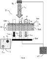
- the figure 1 illustrates a schematic view of a device D for detecting at least one predetermined particle P.
- Particle P is the particle that device D aims to detect. This particle is known and predetermined during a design phase of the device (see below). This particle P has a refractive index n 3 and an absorption line (or peak) at a resonant wavelength ⁇ res .
- the Kramers-Kronig relations connect in a known manner the imaginary part n 3, im and the real part of the refractive index n 3, r .
- This relationship induces, at the resonant absorption at the resonance wavelength ⁇ res , a sudden variation of the real part of the refractive index n 3, r .
- the variation in the refractive index of the particle makes it possible to measure the phase changes induced at the absorption length using an optical cavity.
- Device D of the figure 1 includes a coherent, wavelength tunable SL light source.
- This source is suitable for emitting incident radiation L in , coherent, at a plurality of distinct wavelengths ⁇ i i ⁇ [1, m], included in a spectral region of variation of the refractive index ⁇ ⁇
- the light source is configured to successively emit the wavelengths, i.e. one by one over time.
- ⁇ res is for example centered on the resonance wavelength ⁇ res and of width equal to the width at half height FWHM ⁇ res of the absorption peak at the wavelength ⁇ res , as in the example of figure 2 .
- ⁇ res is centered on the resonance wavelength ⁇ res and of width equal to 1.5 ⁇ FWHM ⁇ res of the absorption peak at the wavelength ⁇ res .
- the light source SL comprises an optical collimation system, adapted so that the incident radiation emitted by the light source is collimated.
- This optical collimation system can, for example, be a lens whose object focal plane comprises the source points of the incident radiation.
- An interferometric element EI of the device D is arranged so as to be illuminated by the incident radiation L in .
- This interferometric element comprises at least two superimposed layers, a so-called thin CM layer placed above a layer called Sub substrate, both transparent in the spectral region of variation of the refractive index ⁇ ⁇
- transparent is meant here that each layer has a transmission greater than 50%, preferably 90% in the spectral region.
- the interferometric element EI is configured so as to be an optical cavity of the Fabry-Perot type forming wavelength fringes in transmission.
- the principle of the invention is to detect a phase shift between these fringes obtained from Fabry-Pérot without joined particles and fringes obtained from Fabry-Pérot with joined particles. Indeed, the presence of particles joined to the surface Sm of the thin layer locally modifies the reflection coefficient of the surface where they are contiguous, which leads to a phase shift of the reflection coefficient (see below).
- the element EI is configured so that the phase shift of the transmission curve as a function of the wavelength of a stack formed by at least one particle attached to the interferometric element on the one hand, and of the interferometric element alone on the other hand, is not constant in the spectral region.
- a refractive index n 2 and a thickness e 2 of the thin film being determined from an index n 1 of the substrate and the resonance wavelength ⁇ res such as the interferometric element (EI) forms a Fabry-Pérot cavity with or without the P particle adjoining; and generates an inversion of the contrast of the fringes resulting from the Fabry-Pérot without joined particles and of the fringes resulting from the Fabry-Pérot with joined particles, in the spectral region of variation of the refractive index ⁇ ⁇
- ⁇ res the refractive index
- the device D uses the principle of IR absorption of the particles P which will locally modify the reflection coefficient of the surface Sm where they are contiguous. Indeed, the reflection coefficient of the surface Sm at the resonance wavelength of the sample ⁇ res will be modified during the presence of the particles, thus modifying the flux of the incident radiation reflected or transmitted.
- the transmission of the incident radiation by the interferometric element is modeled by the formalism of the Abels matrix.
- This formalism of thin layers is suitable because the P particles to be detected are generally surrounded by a liquid film (water, sweat, sebum). For a hydrophilic Sm surface, these particles will tend to spread out to form a film of thin thickness e 3 .
- the use of this formalism assumes that a dimension in a longitudinal direction of joined P particles is greater by at least a factor of 10 than the thickness e 3 of joined P particles.
- the figure 3 represents the transmission of the interferometric element of the device for detecting figure 1 alone, as a function of the wavelength of the incident radiation (curve 1).
- the figure 3 also represents the transmission, as a function of the wavelength of the incident radiation, of the stack formed by a thickness of 250 nm (curve 2), 500 nm (curve 3) and 750 nm (curve 4) respectively of 1000nm (curve 5) of joined PDMS particles and the interferometric element EI.
- the oscillations of the transmission as a function of the wavelength are due to the passage of constructive to destructive interference (or the reverse) produced by the rays of the incident radiation reflected or transmitted by the various interfaces of the interferometric element during 'a change in wavelength.
- the figure 3 makes it possible to directly observe the effect of the absorption of different thicknesses of contiguous P particles, greatly reducing the transmission of curves 2 to 5 with respect to curve 1.
- the thickness e 2 of the thin layer is configured so that there exists a predetermined thickness e 30 of particles contiguous and traversed by the incident radiation, such as the contrast of the oscillations of the transmission as a function of the wavelength of such a stack is zero or substantially zero over a spectral range included in the spectral region ⁇ ⁇
- substantially zero is meant a contrast of less than 10%.
- Device D of the figure 1 additionally includes a matrix sensor or Det detector.
- This detector is suitable for detecting an image comprising a first portion P 1 resulting from the detection of the incident radiation transmitted L TBG by the interferometric element alone and a second portion P 2 resulting from the detection of the incident radiation transmitted L TP by the element interferometric and any particle (this particle being able to be a particle to be detected P or any other object O) attached to the surface Sm of said thin layer.
- the identification of the first portion and of the second portion is based on the fact that the pixels of the first portion have a different intensity from those of the pixels of the second portion.
- the detector detects an associated image I i.
- the device of the figure 1 comprises a UT processor connected to the detector and to the light source SL in order to synchronize these two elements.
- the intensity of the pixels of each image I i (or ADU value for analog to digital unit in English) is proportional to the number of photons detected by this pixel.
- the intensity of the pixels of the image is therefore representative of the transmission of the optical path of the incident radiation between the light source SL and the detector Det.
- the first portion P 1 of the image I i represents the transmission at wavelength ⁇ i of the interferometric element alone
- the second portion of the image I i represents the transmission at wavelength ⁇ i of the stack formed by at least one unspecified particle and the interferometric element.
- Curve 1 of the figure 3 corresponds to the first variation of intensity
- curves 2 to 5 of the figure 3 correspond to the second variation of intensity, when any particle placed side by side is a predetermined particle P.
- the detector is placed as close as possible to the interferometric element and at least in the Fresnel (or near-field) diffraction zone after the interferometric element so that the image is representative of the transmission and not of the far-field diffraction of the transmission (therefore its Fourier transform).
- the processor UT is configured to calculate, as a function of the wavelengths of the incident radiation ⁇ i i ⁇ [1, m], the variation in intensity of at least a first pixel of the first portion, called the first variation F BG and at least a second pixel of the second portion, called the second variation F P.
- the first variation corresponds to the transmission, as a function of the wavelengths of the incident radiation ⁇ i i ⁇ [1, m], of the interferometric element alone.
- the second variation corresponds to the transmission, as a function of the wavelengths of the incident radiation ⁇ i i ⁇ [1, m], of the stack formed by at least one contiguous particle and the interferometric element.
- the processor UT is configured to determine an evolution, as a function of the wavelengths of the incident radiation ⁇ i i ⁇ [1, m], of a phase shift ⁇ i between the first variation and the second variation. Finally, the processor is configured to detect the contiguous particle when the phase shift ⁇ i is not constant as a function of the wavelengths of the incident radiation ⁇ i i ⁇ [1, m].
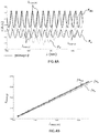
- the figure 4A illustrates the first variation F BG and the second variation Fp obtained for the example of figure 3 , for a PDMS particle thickness of 1000nm.
- the abscissa of these variations is the wavelength of the incident radiation and the ordinate is the intensity of the first and second pixel, respectively.
- the dotted lines of the figure 4A point the maximums local ⁇ max, BG and ⁇ max, P of the first and of the second variation, respectively, and make it possible to graphically visualize the evolution of the phase shift ⁇ i between the first variation F BG and the second variation F P , as a function of the wavelength ⁇ i of the incident radiation.
- the plurality of distinct wavelengths ⁇ i , i ⁇ [1, n ] of the incident radiation are emitted successively so that the wavelengths lie between a length lower wavelength ⁇ inf and a higher wavelength ⁇ sup , where ⁇ inf (respectively ⁇ sup ) is the wavelength for which the real part of the refractive index of the particle is minimum (respectively maximum) on the variation region.
- ⁇ inf (respectively ⁇ sup ) is the wavelength for which the real part of the refractive index of the particle is minimum (respectively maximum) on the variation region.
- the plurality of distinct wavelengths ⁇ i , i ⁇ [1, n ] comprises a first plurality of wavelengths and a second plurality wavelengths.
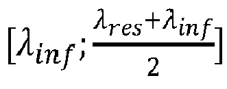
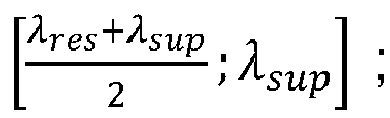
- the first plurality of wavelengths are included in a spectral interval IS 1 as it is ⁇ inf ⁇ res + ⁇ inf 2 and the second plurality of wavelengths is included in a spectral interval IS 2 such that ⁇ res + ⁇ sup 2 ⁇ sup .
- the processor is therefore configured to calculate a first part of the first and of the second variation F BG, 1 and F o, 1 , respectively, associated with the first plurality of wavelengths.
- the processor is configured to calculate a second part of the first and of the second variation, respectively F BG, 2 and F o, 2 , associated with the second plurality of wavelengths.
- the first plurality of wavelengths must allow the determination of at least one period of the oscillations of the first part of the first variation and of the second variation in order to allow the determination of a phase shift between the first and second variation.
- the second plurality of wavelengths must allow the determination of at least one period of the oscillations of the second part of the first variation and of the second variation. These conditions are necessary in order to be able to determine an evolution of the phase shift as a function of the wavelength.
- the lower wavelength and the upper wavelength are located on either side of the resonance wavelength and correspond to a maximum variation of the real part of the refractive index n 3 .
- the detection of the particle P is then facilitated.
- this embodiment makes it possible to vary the wavelength of the incident radiation only around two distinct spectral zones, less extensive than the spectral region ⁇ ⁇
- the wavelengths of the first plurality and the second plurality cover at least 3 cm -1 to 5 cm -1 and are separated by about 100 cm -1 to 150 cm -1 in order to be able to calculate the first and second variation.
- the first wavelength range corresponds to the tunability range of a discrete QCL laser and the second corresponds to the quantum well gain range of the layer stack of the QCL laser.
- the plurality of wavelengths is chosen so that the wavelengths sample the whole of a spectral region between the wavelength lower ⁇ inf and the upper wavelength ⁇ sup .
- the first and the second variation then to determine the evolution phase shift as simply as possible, that is to say by scanning the entire spectral region with the aid of the incident radiation.
- Device D has the advantage of being a "lensless” imaging device which is therefore easy to align and use and which allows rapid detection of predetermined P particles.
- Another advantage of device D of the figure 1 is that it makes it possible to be freed from the non-resonant absorption of an object O, that is to say an object which absorbs on the spectral region but which does not have an absorption line at or in the vicinity of ⁇ res , such as for example water (see figure 6 ). This means that the presence of such an object O attached to a surface Sm of the thin layer CM will not lead to the erroneous detection of a particle P to be detected by the processor UT.
- an object O that is to say an object which absorbs on the spectral region but which does not have an absorption line at or in the vicinity of ⁇ res , such as for example water (see figure 6 ).
- the figure 4A also presents a second variation F o of the intensity of a second pixel of a second portion P 2, o of the image I i resulting from the detection of the incident radiation of wavelength ⁇ i transmitted L TO by the stack formed by the object O attached to the surface Sm of the interferometric element, and the interferometric element (see figure 6 ).
- This second variation F o is determined by the processor in the same way as specified above.
- the processor determines the function fn o representing the wavelengths ⁇ max, 0 of the local maxima of the second variation as a function of the wavelengths ⁇ max, BG of the local maxima of the first variation, on the spectral region ⁇ ⁇
- the object O absorbs at wavelengths ⁇ i , this absorption is not resonant which implies that a phase shift between the first variation and the second variation F o is constant as a function of the wavelength of the incident radiation.
- the slope of the function fn 0 is equal to 1 and the processor does not associate the object O with a particle P to be detected.
- the light source is a tunable laser source emitting over a spectral range between 3 ⁇ m and 12 ⁇ m and the resonance wavelength ⁇ res . of the predetermined particle to be detected P is included in this spectral range.
- this source is a quantum cascade laser (QCL). QCLs have the advantage of being compact and of exhibiting very good wavelength tunability.
- the source is an optical parametric oscillator (OPO).
- the thin film is made of ZnS, ZnSe, CdSe, SiN, AIN, Ta2O5, TiO2, ZrO2, amorphous carbon, chalcogenide and the substrate is made of Si or Ge
- the material of the thin film is identical to the material of the substrate and the surface of the thin film is structured so that the effective index of the thin film perceived by the incident radiation is adapted as specified previously.
- structured is meant here that the layer has a pattern repeated in a longitudinal direction of the thin layer, with a half-period less than the plurality of distinct wavelengths ⁇ i i ⁇ [1, m] of the radiation. incident.
- the structuring of the thin layer can be carried out with all of the techniques known to those skilled in the art, such as electron beam lithography or EUV lithography.
- the diameter of the incident radiation during illumination of the interferometric element is greater than or equal to the dimension of the detector Det, that is to say greater than or equal to 1 cm and a longitudinal dimension of the interferometric element is greater than or equal to the dimension of the detector Det.
- the matrix sensor of the invention is a bolometer matrix, an infrared photodetector of the mercury-cadmium telluride (MCT) type, a hybrid imager (combining the MCT and QWIP technologies) or else a pyrometer matrix.
- MCT mercury-cadmium telluride
- hybrid imager combining the MCT and QWIP technologies
- the resonance wavelength ⁇ res is between 3 ⁇ m and 12 ⁇ m
- the one or more particles P to be detected are particles of explosives, biomolecules or any object having an infrared signature.
Landscapes
- Chemical & Material Sciences (AREA)
- Physics & Mathematics (AREA)
- General Physics & Mathematics (AREA)
- Immunology (AREA)
- Life Sciences & Earth Sciences (AREA)
- Analytical Chemistry (AREA)
- Biochemistry (AREA)
- General Health & Medical Sciences (AREA)
- Pathology (AREA)
- Health & Medical Sciences (AREA)
- Dispersion Chemistry (AREA)
- Spectroscopy & Molecular Physics (AREA)
- Mathematical Physics (AREA)
- Investigating Or Analysing Materials By Optical Means (AREA)
- Investigating, Analyzing Materials By Fluorescence Or Luminescence (AREA)
- Photometry And Measurement Of Optical Pulse Characteristics (AREA)
Abstract
Dispositif de détection (D) d'au moins une particule (P) prédéterminée comprenant :- un élément interférométrique (EI) agencé de manière à être illuminé par un rayonnement incident (L<sub>in</sub>) et comprenant au moins une couche dite mince (CM) disposée au dessus d'une couche dite substrat (Sub), ladite particule étant accolée à une surface (Sm) de ladite couche mince, l'élément interférométrique (EI) formant une cavité Fabry-Pérot avec ou sans particule P accolée;- un capteur matriciel (Det) adapté pour détecter une image comprennant une première portion (P<sub>1</sub>) issue de la détection du rayonnement incident transmis (L<sub>TBG</sub>) par l'élément interférométrique seul et une deuxième portion (P<sub>2</sub>) issue de la détection du rayonnement incident transmis (L<sub>TP</sub>) par l'élement interférométrique et une particule quelconque (O, P) accolée à une surface (Sm) de ladite couche mince;- un processeur (UT) relié au capteur et configuré :- pour calculer, en fonction de longueurs d'onde du rayonnement incident λ<sub>i</sub> i∈[1,m], la variation d'intensité d'au moins un premier pixel de la première portion, dite première variation (F<sub>BG</sub>) et d'au moins un deuxième pixel de la deuxième portion, dite deuxième variation (F<sub>P</sub>),- pour déterminer une évolution, en fonction des longueurs d'onde du rayonnement incident λ<sub>i</sub> i∈[1,m], d'un déphasage φ<sub>i</sub> entre la première variation et la deuxième variation ;- pour détecter la particule accolée lorsque le déphasage φ<sub>i</sub> n'est pas constant en fonction des longueurs d'onde du rayonnement incident λ<sub>i</sub> i∈[1,m].Device for detecting (D) at least one predetermined particle (P) comprising: - an interferometric element (EI) arranged so as to be illuminated by incident radiation (L <sub> in </sub>) and comprising at least a so-called thin layer (CM) disposed above a so-called substrate layer (Sub), said particle being attached to a surface (Sm) of said thin layer, the interferometric element (EI) forming a Fabry-Perot cavity with or without contiguous P particle; - a matrix sensor (Det) suitable for detecting an image comprising a first portion (P <sub> 1 </sub>) resulting from the detection of the incident transmitted radiation (L <sub> TBG </sub> ) by the interferometric element alone and a second portion (P <sub> 2 </sub>) resulting from the detection of the incident radiation transmitted (L <sub> TP </sub>) by the interferometric element and any particle (O, P) contiguous to a surface (Sm) of said thin layer; - a processor (UT) connected to the sensor and configured: - to calculate, according to of wavelengths of the incident radiation λ <sub> i </sub> i∈ [1, m], the variation in intensity of at least a first pixel of the first portion, called the first variation (F <sub> BG </sub>) and at least a second pixel of the second portion, called the second variation (F <sub> P </sub>), - to determine an evolution, as a function of the wavelengths of the incident radiation λ <sub> i </sub> i∈ [1, m], by a phase shift φ <sub> i </sub> between the first variation and the second variation; - to detect the joined particle when the phase shift φ < sub> i </sub> is not constant as a function of the wavelengths of the incident radiation λ <sub> i </sub> i∈ [1, m].
Description
La présente invention concerne le domaine de la détection de particules et plus particulièrement de la détection de particules par absorption infrarouge.The present invention relates to the field of particle detection and more particularly to the detection of particles by infrared absorption.
Dans de nombreux domaines d'application comme l'agro-alimentaire, la défense ou la chimie, la détection et l'identification de particules sont nécessaires dans le but de donner l'alerte d'une éventuelle attaque ou contamination. De nombreuses techniques connues de l'homme de l'art permettent de déterminer une composition chimique d'un échantillon.In many fields of application such as the food industry, defense or chemistry, the detection and identification of particles are necessary in order to give the alert of a possible attack or contamination. Numerous techniques known to those skilled in the art make it possible to determine a chemical composition of a sample.
La spectroscopie infrarouge à transformée de Fourier (FTIR) est une technique analytique extrêmement répandue dans laquelle les molécules de l'échantillon absorbent le rayonnement incident modifiant ainsi leurs énergies de vibration. Selon les liaisons et les fonctions chimiques présentes dans l'échantillon, un spectre infrarouge (IR) caractéristique est obtenu.Fourier transform infrared spectroscopy (FTIR) is an extremely popular analytical technique in which molecules in the sample absorb the incident radiation thus changing their vibrational energies. Depending on the bonds and chemical functions present in the sample, a characteristic infrared (IR) spectrum is obtained.
Outre la spectroscopie FTIR, il existe une multitude de techniques permettant d'identifier des particules au sein d'un échantillon comme la spectrométrie Raman, la spectrométrie sur plasma induite par laser (LIBS), ou encore la méthode de photo-fragmentation induite par la fluorescence (PF-LIF), spécifique aux liaisons NO2.In addition to FTIR spectroscopy, there are a multitude of techniques for identifying particles within a sample such as Raman spectrometry, laser-induced plasma spectrometry (LIBS), or the photo-fragmentation method induced by fluorescence (PF-LIF), specific for NO2 bonds.
Les techniques mettant en jeu l'absorption infrarouge peuvent être déclinées suivant plusieurs modalités :
- l'imagerie IR en transmission ou en rétrodiffusion, par absorption directe de la lumière par la particule. Dans ces méthodes, la puissance optique collectée diminue en présence de l'échantillon. Il est connu d'analyser un gaz généré par la décomposition de l'échantillon soumis à un laser intense pulsé en rétrodiffusion moyen infrarouge (MIR). Cette technique d'imagerie dite passive permet de détecter et d'identifier des nuages de gaz. Il n'est pas possible d'utiliser cette technique pour des objets de petites dimensions comme des particules puisque le chemin optique parcouru dans l'objet est trop petit.
- l'imagerie thermique active, par mesure de l'élévation de température de la particule soumise à un flux laser IR. La particule absorbe le rayonnement laser, le flux thermique collecté va augmenter. Cette technique est très dépendante du substrat où se trouve la particule. En effet, l'échauffement induit par l'absorption du laser va être transmis très rapidement au substrat, ce qui rend la détection très compliquée.
- la photo-acoustique qui peut être séparée en 4 étapes :
- (1) absorption du rayonnement laser par le gaz excitant ainsi les niveaux d'énergies rotationnels, électroniques et vibrationnels;
- (2) dans le cas d'excitations ro-vibrationnelles, désexcitation du gaz préférentiellement par des collisions moléculaires qui vont se traduire par un transfert d'énergie de rotation/vibration et énergie cinétique créant un chauffage localisé du gaz ;
- (3) génération d'une onde acoustique et d'une onde thermique provoquée par l'expansion due au chauffage du gaz ;
- (4) détection par le microphone du signal acoustique. L'amplitude de vibration du microphone est représentative de la concentration du gaz et la longueur d'onde du rayonnement laser absorbée par le gaz indique sa composition. Cette méthode est très intéressante mais elle ne permet pas d'avoir une image d'une zone. Il faudrait scanner le laser sur l'échantillon ce qui demande de l'instrumentation et du temps de mesure.
- IR imaging in transmission or backscattering, by direct absorption of light by the particle. In these methods, the collected optical power decreases in the presence of the sample. It is known practice to analyze a gas generated by the decomposition of the sample subjected to an intense pulsed laser in medium infrared backscattering (MIR). This so-called passive imaging technique makes it possible to detect and identify gas clouds. It is not possible to use this technique for small objects such as particles since the optical path traversed in the object is too small.
- active thermal imaging, by measuring the temperature rise of the particle subjected to an IR laser flux. The particle absorbs the laser radiation, the collected heat flux will increase. This technique is very dependent on the substrate where the particle is located. In fact, the heating induced by the absorption of the laser will be transmitted very quickly to the substrate, which makes detection very complicated.
- photo-acoustics which can be separated into 4 steps:
- (1) absorption of laser radiation by the gas thereby exciting rotational, electronic and vibrational energy levels;
- (2) in the case of ro-vibrational excitations, de-excitation of the gas preferentially by molecular collisions which will result in a transfer of rotational / vibrational energy and kinetic energy creating localized heating of the gas;
- (3) generation of an acoustic wave and a thermal wave caused by the expansion due to the heating of the gas;
- (4) detection by the microphone of the acoustic signal. The vibration amplitude of the microphone is representative of the concentration of the gas and the wavelength of laser radiation absorbed by the gas indicates its composition. This method is very interesting but it does not allow to have an image of an area. It would be necessary to scan the laser on the sample which requires instrumentation and measurement time.
Ces techniques ne permettent donc pas d'obtenir une image résolue spatialement et spectralement avec un dispositif simple et compact.These techniques therefore do not make it possible to obtain a spatially and spectrally resolved image with a simple and compact device.
L'invention vise à pallier certains problèmes de l'art antérieur. A cet effet, un objet de l'invention est un dispositif de détection d'une particule prédéterminée possédant l'avantage d'avoir un grand champ d'imagerie, d'être compact et de nécessiter l'utilisation d'un élément interférométrique peu coûteux à produire et facilement reproductible.The invention aims to overcome certain problems of the prior art. To this end, an object of the invention is a device for detecting a predetermined particle having the advantage of having a large imaging field, of being compact and of requiring the use of a low interferometric element. expensive to produce and easily reproducible.
Un objet de l'invention est une méthode de détection d'au moins une particule prédéterminée, lesdites particules possédant un indice de réfraction n3 et une raie d'absorption à une longueur d'onde de résonance λres , ladite raie d'absorption induisant une variation de l'indice de réfraction sur une région spectrale, ladite méthode comprenant les étapes suivantes :
- A. l'émission d'un rayonnement incident cohérent à une pluralité de longueurs d'onde distinctes λi i∈[1,m], successivement une par une, lesdites longueurs d'ondes étant comprises dans une ladite région spectrale;
pour chaque i∈[1,m] on réalise les étapes suivantes:- A1 : l'illumination, par le rayonnement incident à la longueur d'onde λi , d'un élément : interférométrique comprenant au moins deux couches superposées, une couche dite mince, disposée au dessus d'une couche dite substrat, toutes les deux transparentes à la longueur d'onde λi , ladite particule étant accolée à une surface de ladite couche mince, un indice de réfraction n2 et une épaisseur e2 de la couche mince étant tel que l'élément interférométrique forme une cavité Fabry-Pérot avec ou sans particule accolée et génère une inversion du contraste entre des franges issues du Fabry-Pérot sans particules accolées et des franges issues du Fabry-Pérot avec particules accolées;
- A2 : l'acquisition, par un capteur matriciel, d'une image Ii comprennant une première portion issue de la détection du rayonnement incident transmis par l'élément interférométrique seul et une deuxième portion issue de la détection du rayonnement incident transmis par l'élement interférométrique et une particule quelconque accolée à une surface de ladite couche mince, des pixels de la première portion présentant une intensité différente de celles des pixels de la deuxième portion;
- B. le calcul de la variation d'intensité, en fonction des longueurs d'onde du rayonnement incident λi i∈[1,m], d'au moins un premier pixel de la première portion, dite première variation et d'au moins un deuxième pixel de la deuxième portion, dite deuxième variation ;
- C. la détermination d'une évolution, en fonction des longueurs d'onde du rayonnement incident λi i∈[1,m], d'un déphasage φi entre la première variation et la deuxième variation ;
- D. la détection de la particule accolée lorsque le déphasage φi n'est pas constant en fonction des longueurs d'onde du rayonnement incident λi i∈[1,m].
- A. the emission of incident coherent radiation at a plurality of distinct wavelengths λ i i∈ [1, m], successively one by one, said wavelengths being included in a said spectral region;
for each i∈ [1, m] we carry out the following steps:- A1: illumination, by incident radiation at wavelength λ i , of an: interferometric element comprising at least two superimposed layers, a so-called thin layer, placed above a layer called substrate, both transparent at the wavelength λ i , said particle being attached to a surface of said thin layer, a refractive index n 2 and a thickness e 2 of the thin layer being such that the interferometric element forms a Fabry-Perot cavity with or without contiguous particle and generates an inversion of the contrast between fringes obtained from Fabry-Pérot without contiguous particles and fringes obtained from Fabry-Pérot with contiguous particles;
- A2: the acquisition, by a matrix sensor, of an image I i comprising a first portion resulting from the detection of the incident radiation transmitted by the interferometric element alone and a second portion resulting from the detection of the incident radiation transmitted by the interferometric element and any particle attached to a surface of said thin layer, pixels of the first portion having an intensity different from those of the pixels of the second portion;
- B. the calculation of the variation in intensity, as a function of the wavelengths of the incident radiation λ i i∈ [1, m], of at least a first pixel of the first portion, called the first variation, and at least a second pixel of the second portion, called the second variation;
- C. determining an evolution, as a function of the wavelengths of the incident radiation λ i i∈ [1, m], of a phase shift φ i between the first variation and the second variation;
- D. the detection of the contiguous particle when the phase shift φ i is not constant as a function of the wavelengths of the incident radiation λ i i∈ [1, m].
Selon des modes particuliers de l'invention :
- dans l'étape B, une identification du premier et du deuxième pixel est réalisée par traitement d'image en comparant l'intensité des pixels d'une image Ii associée à une longueur d'onde λi ;
- dans l'étape C, la détermination de l'évolution du déphasage φi comprend la détermination d'une fonction fnp représentant les longueurs d'onde λmax,P des maximums locaux de la deuxième variation en fonction des longueurs d'onde λmax,BG des maximums locaux de la première variation ;
- lesdites longueurs d'onde distinctes λi i∈[1,m] sont comprises entre une longueur d'onde inférieure λinf pour laquelle une partie réelle de l'indice de réfraction de la particule est minimum sur ladite région spectrale, et une longueur d'onde supérieure λsup, pour laquelle une partie réelle de l'indice de réfraction de la particule est maximum sur la région spectrale ;
- la pluralité de longueurs d'onde distinctes λi i∈[1,m], comprend une première pluralité de longueurs d'onde et une deuxième pluralité de longueurs d'onde, ladite première pluralité de longueur d'onde étant comprise dans un intervalle spectral tel quel
- dans l'étape A, la pluralité de longueur d'onde distinctes λi i∈[1,m] est choisie, de manière à ce que les longueurs d'onde sont réparties sur l'ensemble d'une portion de ladite région spectrale comprise entre la longueur d'onde inférieure λinf et la longueur d'onde supérieure λsup ;
- ledit élément interférométrique est adapté pour que, pour une épaisseur prédéterminée e30 de particules P accolées et traversées par le rayonnement incident, le contraste de la deuxième variation soit nul ou sensiblement nul sur une plage spectrale incluse dans la région de spectrale.
- in step B, an identification of the first and of the second pixel is carried out by image processing by comparing the intensity of the pixels of an image I i associated with a wavelength λ i ;
- in step C, the determination of the evolution of the phase shift φ i comprises the determination of a function fn p representing the wavelengths λ max, P of the local maxima of the second variation as a function of the wavelengths λ max, BG of the local maxima of the first variation;
- said distinct wavelengths λ i i∈ [1, m] are between a lower wavelength λ inf for which a real part of the refractive index of the particle is minimum over said spectral region, and a length of higher wave λ sup , for which a real part of the refractive index of the particle is maximum over the spectral region;
- the plurality of distinct wavelengths λ i i∈ [1, m], comprises a first plurality of wavelengths and a second plurality of wavelengths, said first plurality of wavelengths being included in an interval spectral as is
- in step A, the plurality of distinct wavelengths λ i i∈ [1, m] is chosen, so that the wavelengths are distributed over the whole of a portion of said spectral region between the lower wavelength λ inf and the upper wavelength λ sup ;
- said interferometric element is adapted so that, for a predetermined thickness e 30 of particles P joined together and crossed by the incident radiation, the contrast of the second variation is zero or substantially zero over a spectral range included in the spectral region.
Un autre objet de l'invention est un dispositif de détection d'au moins une particule prédéterminée, ladite particule possédant un indice de réfraction n3 et une raie d'absorption à une longueur d'onde de résonance λres , ladite raie d'absorption induisant une variation de l'indice de réfraction sur une région spectrale Δλ|λres , ledit dispositif comprenant :
- une source de lumière (SL) cohérente, accordable en longueur d'onde et adaptée pour émettre un rayonnement incident (Lin) cohérent à une pluralité de longueurs d'onde distinctes λi i∈[1,m], configurée pour émettre successivement lesdites longueurs d'onde, lesdites longueurs d'ondes étant comprises dans ladite région spectrale ;
- un élément interférométrique (EI) agencé de manière à être illuminé par le rayonnement incident (Lin) et comprenant au moins une couche dite mince (CM) disposée au dessus d'une couche dite substrat (Sub), toutes les deux transparentes dans ladite région spectrale, ladite particule étant accolée à une surface (Sm) de ladite couche mince, un indice de réfraction n2 et une épaisseur e2 de la couche mince étant déterminés à partir d'un indice n1 du substrat et de la longueur d'onde de résonance λres tel que l'élément interférométrique (EI) forme une cavité Fabry-Pérot avec ou sans particule P accolée;
- un capteur matriciel (Det) adapté pour détecter une image comprennant une première portion (P1) issue de la détection du rayonnement incident transmis (LTBG) par l'élément interférométrique seul et une deuxième portion (P2) issue de la détection du rayonnement incident transmis (LTP) par l'élement interférométrique et une particule quelconque (O, P) accolée à une surface (Sm) de ladite couche mince, des pixels de la première portion présentant une intensité différente de celles des pixels de la deuxième portion;
- un processeur (UT) relié au capteur et configuré :
- pour calculer, en fonction des longueurs d'onde du rayonnement incident λi i∈[1,m], la variation d'intensité d'au moins un premier pixel de la première portion, dite première variation (FBG) et d'au moins un deuxième pixel de la deuxième portion, dite deuxième variation (FP),
- pour déterminer une évolution, en fonction des longueurs d'onde du rayonnement incident λi i∈[1,m], d'un déphasage φi entre la première variation et la deuxième variation ;
- pour détecter la particule accolée lorsque le déphasage φi n'est pas constant en fonction des longueurs d'onde du rayonnement incident λi i∈[1,m].
- a coherent light source (SL), tunable in wavelength and adapted to emit incident radiation (L in ) coherent at a plurality of distinct wavelengths λ i i∈ [1, m], configured to successively emit said wavelengths, said wavelengths being included in said spectral region;
- an interferometric element (EI) arranged so as to be illuminated by the incident radiation (L in ) and comprising at least one so-called thin layer (CM) disposed above a so-called substrate layer (Sub), both transparent in said spectral region, said particle being attached to a surface (Sm) of said thin film, a refractive index n 2 and a thickness e 2 of the thin film being determined from an index n 1 of the substrate and the length d λ res resonance wave such that the interferometric element (EI) forms a Fabry-Perot cavity with or without contiguous P particle;
- a matrix sensor (Det) suitable for detecting an image comprising a first portion (P 1 ) resulting from the detection of the incident radiation transmitted (L TBG ) by the interferometric element alone and a second portion (P 2 ) resulting from the detection of the incident radiation transmitted (L TP ) by the interferometric element and any particle (O, P) attached to a surface (Sm) of said thin layer, pixels of the first portion having an intensity different from those of the pixels of the second portion;
- a processor (UT) connected to the sensor and configured:
- to calculate, as a function of the wavelengths of the incident radiation λ i i∈ [1, m], the variation in intensity of at least a first pixel of the first portion, called the first variation (F BG ) and of at least a second pixel of the second portion, called the second variation (F P ),
- to determine an evolution, as a function of the wavelengths of the incident radiation λ i i∈ [1, m], of a phase shift φ i between the first variation and the second variation;
- to detect the contiguous particle when the phase shift φ i is not constant as a function of the wavelengths of the incident radiation λ i i∈ [1, m].
Selon des modes particuliers de l'invention :
- - l'épaisseur e2 de la couche mince est comprise entre 0.8 × λres /4n 1 et 1.2 × λres /4n 1 avec n 1 un indice de réfraction du substrat, et dans lequel l'indice de de réfraction n 2 de la couche mince est tel que


- - un matériau de la couche mince est identique au matériau du substrat et dans lequel ladite surface de la couche mince est structurée de manière à ce que l'indice effectif de la couche mince perçu par le rayonnement incident soit tel que

- - l'épaisseur e2 de la couche mince est adaptée pour que, pour une épaisseur prédéterminée e30 de particules accolées et traversées par le rayonnement incident, le contraste de la deuxième variation soit nul ou sensiblement nul sur une plage spectrale incluse dans la région spectrale ;
- - la couche mince est en ZnS, ZnSe, CdSe, SiN, AlN, Ta2O5, TiO2, ZrO2 et le substrat est en Si ou Ge ;
- - the thickness e 2 of the thin film is between 0.8 × λ res / 4 n 1 and 1.2 × λ res / 4 n 1 with n 1 a refractive index of the substrate, and in which the refractive index n 2 of the thin layer is such that
- a material of the thin film is identical to the material of the substrate and in which said surface of the thin film is structured so that the effective index of the thin film perceived by the incident radiation is such that
- the thickness e 2 of the thin layer is adapted so that, for a predetermined thickness e 30 of particles joined together and crossed by the incident radiation, the contrast of the second variation is zero or substantially zero over a spectral range included in the region spectral;
- the thin layer is made of ZnS, ZnSe, CdSe, SiN, AlN, Ta2O5, TiO2, ZrO2 and the substrate is made of Si or Ge;
Un autre objet de l'invention est un procédé de fabrication d'un élément interférométrique pour dispositif de détection comprenant un élément interférométrique comprenant au moins, une couche dite mince disposée au dessus d'une couche dite substrat, toutes les deux transparentes dans une région spectrale, ledit procédé comprenant une phase de conception dudit élément interférométrique et une étape de fabrication matérielle dudit élément interférométrique ainsi conçu caractérisé en ce que la phase de conception comprend les étapes suivantes :
- la sélection d'au moins une particule (P) à détecter présentant une raie d'absorption à une longueur d'onde de résonance λres comprise dans ladite région spectrale ;
- la sélection d'un substrat d'indice de réfraction n1 ;
- la détermination d'une épaisseur e2 et d'un indice de réfraction n2 de la couche mince verifiant les conditions suivantes à la longueur d'onde de résonance :
- l'élément interférométrique (EI) forme une cavité Fabry-Pérot avec ou sans particule P accolée et génère une inversion du contraste entre des franges issues du Fabry-Pérot sans particules accolées et des franges issues du Fabry-Pérot avec particules accolées, et

et 
- l'élément interférométrique (EI) forme une cavité Fabry-Pérot avec ou sans particule P accolée et génère une inversion du contraste entre des franges issues du Fabry-Pérot sans particules accolées et des franges issues du Fabry-Pérot avec particules accolées, et
- selecting at least one particle (P) to be detected exhibiting an absorption line at a resonant wavelength λ res included in said spectral region;
- selecting a substrate of refractive index n 1 ;
- the determination of a thickness e 2 and of a refractive index n 2 of the thin film verifying the following conditions at the resonance wavelength:
- the interferometric element (EI) forms a Fabry-Pérot cavity with or without an attached P particle and generates an inversion of the contrast between fringes obtained from Fabry-Pérot without joined particles and fringes obtained from Fabry-Pérot with joined particles, and
- the interferometric element (EI) forms a Fabry-Pérot cavity with or without an attached P particle and generates an inversion of the contrast between fringes obtained from Fabry-Pérot without joined particles and fringes obtained from Fabry-Pérot with joined particles, and
Selon un mode de réalisation particulier de l'invention, ladite longueur d'onde de résonance λres est comprise entre 3µm et 12µm, et dans laquelle la ou les particules à détecter sont des particules d'explosifs, des biomolécules.According to a particular embodiment of the invention, said resonance wavelength λ res is between 3 μm and 12 μm , and in which the particle or particles to be detected are particles of explosives, biomolecules.
D'autres caractéristiques, détails et avantages de l'invention ressortiront à la lecture de la description faite en référence aux dessins annexés donnés à titre d'exemple et qui représentent, respectivement :
- [
Fig.1 ] une vue schématique d'un dispositif de détection selon l'invention ; - [
Fig.2 ], la partie imaginaire et réelle de l'indice de réfraction d'un exemple de particule prédéterminée ; - [
Fig.3 ], la transmission d'un élément interférométrique du dispositif de détection selon l'invention, en fonction de la longueur d'onde du rayonnement incident, pour une pluralité d'épaisseur de particules à détecter accolées à une surface de l'élément interférométrique ; - [
Fig.4A] et [Fig.4B ], respectivement, la transmission d'un élément interférométrique du dispositif de détection selon l'invention, en fonction de la longueur d'onde du rayonnement incident, dans différente condition, et un graphique présentant l'évolution, en fonction de la longueur d'onde du rayonnement incident, du déphasage entre deux franges d'interférences obtenues par la traversée par le rayonnement incident d'une portion différente de l'élément interférométrique ; - [
Fig.5 ] une représentation des intervalles spectraux permettant la détermination d'un déphasage selon un mode de réalisation de l'invention ; - [
Fig.6 ] une vue schématique d'un dispositif de détection selon l'invention ; - [
Fig.7 ] une représentation schématique d'une méthode de détection de particules selon l'invention.
- [
Fig. 1 ] a schematic view of a detection device according to the invention; - [
Fig. 2 ], the imaginary and real part of the refractive index of an example of a predetermined particle; - [
Fig. 3 ], the transmission of an interferometric element of the detection device according to the invention, as a function of the wavelength of the incident radiation, for a plurality of thicknesses of particles to be detected attached to a surface of the interferometric element; - [
Fig.4A] and [Fig.4B ], respectively, the transmission of an interferometric element of the detection device according to the invention, as a function of the wavelength of the incident radiation, under different conditions, and a graph showing the evolution, as a function of the length d wave of the incident radiation, of the phase shift between two interference fringes obtained by the passing through by the incident radiation of a different portion of the interferometric element; - [
Fig. 5 ] a representation of the spectral intervals allowing the determination of a phase shift according to one embodiment of the invention; - [
Fig. 6 ] a schematic view of a detection device according to the invention; - [
Fig. 7 ] a schematic representation of a method for detecting particles according to the invention.
Dans les figures, sauf contre-indication, les éléments ne sont pas à l'échelle.In the figures, unless otherwise indicated, the elements are not to scale.
La
La particule P est la particule que le dispositif D vise à détecter. Cette particule est connue et prédéterminée lors d'une phase de conception du dispositif (voir plus loin). Cette particule P possède un indice de réfraction n 3 et une raie (ou pic) d'absorption à une longueur d'onde de résonance λres .Particle P is the particle that device D aims to detect. This particle is known and predetermined during a design phase of the device (see below). This particle P has a refractive index n 3 and an absorption line (or peak) at a resonant wavelength λ res .
Les relations de Kramers-Kronig relient de manière connue la partie imaginaire n 3,im et la partie réelle de l'indice de réfraction n 3,r . Cette relation induit, à l'absorption résonante à la longueur d'onde de résonance λres , une variation brutale de la partie réelle de l'indice de réfraction n 3,r . Selon l'invention, la variation de l'indice de réfraction de la particule permet de mesurer les changements de phase induits à la longueur d'absorption à l'aide d'une cavité optique. La
Le dispositif D de la
Selon un mode de réalisation préféré de l'invention, la source de lumière SL comprend un système optique de collimation, adapté pour que le rayonnement incident émis par la source de lumière soit collimaté. Ce système optique de collimation peut, par exemple, être une lentille dont le plan focal objet comprend les points sources du rayonnement incident.According to a preferred embodiment of the invention, the light source SL comprises an optical collimation system, adapted so that the incident radiation emitted by the light source is collimated. This optical collimation system can, for example, be a lens whose object focal plane comprises the source points of the incident radiation.
Un élément interférométrique EI du dispositif D est agencé de manière à être illuminé par le rayonnement incident Lin. Cet élément interférométrique comprend au moins deux couches superposées, une couche dite mince CM disposée au-dessus d'une couche dite substrat Sub, toutes les deux transparentes dans la région spectrale de variation de l'indice de réfraction Δλ| λres associée à ladite raie d'absorption. Par transparente, on entend ici que chaque couche possède une transmission supérieure à 50%, préférentiellement 90% dans la région spectrale.An interferometric element EI of the device D is arranged so as to be illuminated by the incident radiation L in . This interferometric element comprises at least two superimposed layers, a so-called thin CM layer placed above a layer called Sub substrate, both transparent in the spectral region of variation of the refractive index Δ λ | λres associated with said absorption line. By transparent is meant here that each layer has a transmission greater than 50%, preferably 90% in the spectral region.
L'élément interférométrique EI est configuré de manière à être une cavité optique de type Fabry-Pérot formant des franges de longueurs d'onde en transmission. Le principe de l'invention est de détecter un déphasage entre ces franges issues du Fabry-Pérot sans particules accolées et des franges issues du Fabry-Pérot avec particules accolées. En effet, la présence de particules accolées à la surface Sm de la couche mince modifie localement le coefficient de réflexion de la surface où elles sont accolées, ce qui conduit à un déphasage du coefficient de réflexion (voir plus loin).The interferometric element EI is configured so as to be an optical cavity of the Fabry-Perot type forming wavelength fringes in transmission. The principle of the invention is to detect a phase shift between these fringes obtained from Fabry-Pérot without joined particles and fringes obtained from Fabry-Pérot with joined particles. Indeed, the presence of particles joined to the surface Sm of the thin layer locally modifies the reflection coefficient of the surface where they are contiguous, which leads to a phase shift of the reflection coefficient (see below).
Les inventeurs ont mis en évidence qu'un Fabry-Pérot formé d'une seule couche ne permet pas d'observer un déphasage. Ainsi, l'élément EI est configuré de manière à ce que le déphasage de la courbe de la transmission en fonction de la longueur d'onde d'un empilement formé par au moins une particule accolée à l'élément interférométrique d'une part, et de l'élément interférométrique seul d'autre part, ne soit pas constant dans la région spectrale.The inventors have demonstrated that a Fabry-Pérot formed from a single layer does not make it possible to observe a phase shift. Thus, the element EI is configured so that the phase shift of the transmission curve as a function of the wavelength of a stack formed by at least one particle attached to the interferometric element on the one hand, and of the interferometric element alone on the other hand, is not constant in the spectral region.
Après de nombreuses simulations, les inventeurs ont déterminés que la couche mince doit présenter un indice de réfraction n 2 sensiblement décalé de la valeur qui ferait de la couche mince CM une couche antireflet vis-à-vis de l'air à la longueur d'onde d'illumination λres , c'est-à-dire ![]()
![]()
Cette caractéristique se traduit par deux conditions sur les caractéristiques e2 et n2 de la couche mince CM. Plus précisément, un indice de réfraction n2 et une épaisseur e2 de la couche mince étant déterminé à partir d'un indice n1 du substrat et de la longueur d'onde de résonance λres tel que l'élément interférométrique (EI) forme une cavité Fabry-Pérot avec ou sans particule P accolée; et génère une inversion du contraste des franges issues du Fabry-Pérot sans particules accolées et des franges issues du Fabry-Pérot avec particules accolées, dans la région spectrale de variation de l'indice de réfraction Δλ| λres .This characteristic results in two conditions on the characteristics e 2 and n 2 of the thin layer CM. More precisely, a refractive index n 2 and a thickness e 2 of the thin film being determined from an index n 1 of the substrate and the resonance wavelength λ res such as the interferometric element (EI) forms a Fabry-Pérot cavity with or without the P particle adjoining; and generates an inversion of the contrast of the fringes resulting from the Fabry-Pérot without joined particles and of the fringes resulting from the Fabry-Pérot with joined particles, in the spectral region of variation of the refractive index Δ λ | λres .
Selon l'invention, e2 et n2 verifient la condition :
-

-


-
-
Dans la suite, on suppose qu'au moins une particule P est accolée à une surface Sm de ladite couche mince CM.In the following, it is assumed that at least one particle P is attached to a surface Sm of said thin layer CM.
Le dispositif D selon l'invention, utilise le principe de l'absorption IR des particules P qui vont modifier localement le coefficient de réflexion de la surface Sm où elles sont accolées. En effet, le coefficient de réflexion de la surface Sm à la longueur d'onde de résonance de l'échantillon λres va être modifié lors de la présence des particules modifiant ainsi le flux du rayonnement incident réfléchi ou transmis. On définit le coefficient de réflexion Rp pour l'interface entre la surface Sm de la couche mince et une particule P accolée à cette surface par : ![]()
![]()
![]()
![]()
D'une manière connue, la transmission du rayonnement incident par l'élément interférométrique est modélisée par le formalisme des matrices d'Abelès. Ce formalisme de couches minces est adapté car les particules P à détecter sont généralement entourées d'un film liquide (eau, sueur, sébum). Pour une surface Sm hydrophile, ces particules auront tendances à s'étaler pour former un film d'épaisseur fine e3. L'utilisation de ce formalisme suppose qu'une dimension selon une direction longitudinale de particules P accolées est supérieure d'au moins un facteur 10 à l'épaisseur e3 de particules P accolées.In a known manner, the transmission of the incident radiation by the interferometric element is modeled by the formalism of the Abels matrix. This formalism of thin layers is suitable because the P particles to be detected are generally surrounded by a liquid film (water, sweat, sebum). For a hydrophilic Sm surface, these particles will tend to spread out to form a film of thin thickness e 3 . The use of this formalism assumes that a dimension in a longitudinal direction of joined P particles is greater by at least a factor of 10 than the thickness e 3 of joined P particles.
La
La
Pour une même courbe parmi les courbes 2 à 5, la variation de la valeur moyenne de la transmission est due à la variation de la partie imaginaire n 3,im de l'indice de réfraction de la particule P sur la région spectrale Δλ| λres . De manière critique, la
Dans tous les modes de réalisation de l'invention, l'épaisseur e2 de la couche mince est configurée pour qu'il existe une épaisseur prédéterminée e30 de particules accolées et traversées par le rayonnement incident, telle que le contraste des oscillations de la transmission en fonction de la longueur d'onde d'un tel empilement soit nul ou sensiblement nul sur une plage spectrale incluse dans la région spectrale Δλ| λres . Par sensiblement nul, on entend un contraste inférieur à 10%. Cette condition permet l'identification, par le dispositif D, d'une épaisseur particulière et prédéterminée e30 de particules P accolées permettant par exemple de remonter à une concentration dans un milieu ambiant donné. Dans la
Dans l'exemple de la
Le dispositif D de la
L'intensité des pixels de chaque image Ii (ou valeur ADU pour analog to digital unit en anglais) est proportionnelle au nombre de photons détectés par ce pixel. Pour un faisceau collimaté ou situé dans le plan image de l'échantillon, l'intensitédes pixels de l'image est donc représentative de la transmission du trajet optique du rayonnement incident entre la source de lumière SL et le détecteur Det. Aussi, pour chaque i∈[1,m], la première portion P1 de l'image Ii représente la transmission à la longueur d'onde λi de l'élément interférométrique seul, et la deuxième portion de l'image Ii représente la transmission à la longueur d'onde λi de l'empilement formé par au moins une particule quelconque et l'élément interférométrique. La courbe 1 de la
Selon un mode de réalisation de l'invention, le détecteur est placé le plus proche possible de l'élément interférométrique et au moins dans la zone de diffraction de Fresnel (ou de champ proche) après l'élément interférométrique afin que l'image soit représentative de la transmission et non pas de la diffraction en champ lointain de la transmission (donc sa transformée de Fourier).According to one embodiment of the invention, the detector is placed as close as possible to the interferometric element and at least in the Fresnel (or near-field) diffraction zone after the interferometric element so that the image is representative of the transmission and not of the far-field diffraction of the transmission (therefore its Fourier transform).
Le processeur UT est configuré pour calculer, en fonction des longueurs d'onde du rayonnement incident λi i∈[1,m], la variation d'intensité d'au moins un premier pixel de la première portion, dite première variation FBG et d'au moins un deuxième pixel de la deuxième portion, dite deuxième variation FP. La première variation correspond à la transmission, en fonction des longueurs d'onde du rayonnement incident λi i∈[1,m], de l'élément interférométrique seul. La deuxième variation correspond à la transmission, en fonction des longueurs d'onde du rayonnement incident λi i∈[1,m], de l'empilement formé par au moins une particule accolée et l'élément interférométrique.The processor UT is configured to calculate, as a function of the wavelengths of the incident radiation λ i i∈ [1, m], the variation in intensity of at least a first pixel of the first portion, called the first variation F BG and at least a second pixel of the second portion, called the second variation F P. The first variation corresponds to the transmission, as a function of the wavelengths of the incident radiation λ i i∈ [1, m], of the interferometric element alone. The second variation corresponds to the transmission, as a function of the wavelengths of the incident radiation λ i i∈ [1, m], of the stack formed by at least one contiguous particle and the interferometric element.
Le processeur UT est configuré pour déterminer une évolution, en fonction des longueurs d'onde du rayonnement incident λi i∈[1,m], d'un déphasage φi entre la première variation et la deuxième variation. Enfin, le processeur est configuré pour détecter la particule accolée lorsque le déphasage φi n'est pas constant en fonction des longueurs d'onde du rayonnement incident λi i∈[1,m].The processor UT is configured to determine an evolution, as a function of the wavelengths of the incident radiation λ i i∈ [1, m], of a phase shift φ i between the first variation and the second variation. Finally, the processor is configured to detect the contiguous particle when the phase shift φ i is not constant as a function of the wavelengths of the incident radiation λ i i∈ [1, m].
La
Selon un mode de réalisation de l'invention, l'identification par le processeur du premier et du deuxième pixel est réalisée par traitement d'image en comparant l'intensité des pixels de l'une des images Ii i∈[1,m], associée à une longueur d'onde λi . En effet, comme mentionné précédemment, la transmission de l'élément interférométrique seul est inférieure à la transmission de l'empilement formé par au moins une particule P accolée et l'élément interférométrique, sur la région spectrale de variation de l'indice de réfraction Δλ| λres (voir
Selon un mode de réalisation préféré de l'invention, la pluralité de longueurs d'onde distinctes λi , i ∈ [1, n] du rayonnement incident sont émises successivement de manière à ce que les longueurs d'onde soient comprises entre une longueur d'onde inférieure λinf et une longueur d'onde supérieure λsup, où λinf (respectivement λsup ) est la longueur d'onde pour laquelle la partie réelle de l'indice de réfraction de la particule est minimum (respectivement maximum) sur la région de variation. Cette condition permet d'observer le plus grand déphasage possible du coefficient de réflexion RP et donc le plus grand déphasage φi entre la première variation et la deuxième variation.According to a preferred embodiment of the invention, the plurality of distinct wavelengths λ i , i ∈ [1, n ] of the incident radiation are emitted successively so that the wavelengths lie between a length lower wavelength λ inf and a higher wavelength λ sup , where λ inf (respectively λ sup ) is the wavelength for which the real part of the refractive index of the particle is minimum (respectively maximum) on the variation region. This condition makes it possible to observe the greatest possible phase shift of the reflection coefficient R P and therefore the largest phase shift φ i between the first variation and the second variation.
Selon une première variante de ce mode de réalisation préféré de l'invention, illustrée en ![]()
![]()
![]()
![]()
Selon une deuxième variante de ce mode de réalisation préféré de l'invention, la pluralité de longueur d'onde est choisie de manière à ce que les longueurs d'onde échantillonnent l'ensemble d'une région spectrale comprise entre la longueur d'onde inférieure λinf et la longueur d'onde supérieure λsup. Ainsi, pour des longueurs d'onde suffisament proche l'une de l'autre (par exemple séparées d'environ 100 à 150 cm-1), il est possible de calculer précisément la première et la deuxième variation puis de déterminer l'évolution du déphasage le plus simplement possible, c'est-à-dire en balayant la totalité de la région spectrale à l'aide du rayonnement incident.According to a second variant of this preferred embodiment of the invention, the plurality of wavelengths is chosen so that the wavelengths sample the whole of a spectral region between the wavelength lower λ inf and the upper wavelength λ sup . Thus, for wavelengths sufficiently close to each other (for example separated by approximately 100 to 150 cm -1 ), it is possible to precisely calculate the first and the second variation then to determine the evolution phase shift as simply as possible, that is to say by scanning the entire spectral region with the aid of the incident radiation.
Selon un mode de réalisation, la détermination, par le processeur UT, d'une évolution du déphasage φi en fonction des longueurs d'onde du rayonnement incident comprend la détermination d'une fonction fnp représentant les longueurs d'onde λmax,P des maximums locaux de la deuxième variation en fonction des longueurs d'onde λmax,BG des maximums locaux de la première variation, sur la région spéctrale Δλ| λres . La détermination de la fonction fnp est réalisée par interpolation à partir d'au moins deux longueurs d'ondes λmax,P des maximums locaux de la deuxième variation chacune associée à une longueur d'onde λmax,BG de la première variation. La
Le dispositif D possède l'avantage d'être un dispositif d'imagerie « sans lentille » qui est donc facile à aligner et à utiliser et qui permet une détection rapide de particules prédéterminées P.Device D has the advantage of being a "lensless" imaging device which is therefore easy to align and use and which allows rapid detection of predetermined P particles.
Un autre avantage du dispositif D de la
Selon un mode de réalisation, la source de lumière est une source laser accordable émettant sur une gamme spectrale comprise entre 3µm et 12µm et la longueur d'onde de résonance λres . de la particule prédéterminée à détecter P est comprise dans cette gamme spectrale. Selon un mode préférée de l'invention, cette source est un laser à cascade quantique (QCL). Les QCLs possèdent l'avantage d'être compact et de présenter une très bonne accordabilité en longueur d'onde. Alternativement, la source est un oscillateur paramétrique optique (OPO).According to one embodiment, the light source is a tunable laser source emitting over a spectral range between 3 μm and 12 μm and the resonance wavelength λ res . of the predetermined particle to be detected P is included in this spectral range. According to a preferred embodiment of the invention, this source is a quantum cascade laser (QCL). QCLs have the advantage of being compact and of exhibiting very good wavelength tunability. Alternatively, the source is an optical parametric oscillator (OPO).
Selon un mode de réalisation de l'invention, la couche mince est en ZnS, en ZnSe, CdSe, SiN, AIN, Ta2O5, TiO2, ZrO2, carbone amorphe, chalcogénure et le substrat est en Si ou en GeAccording to one embodiment of the invention, the thin film is made of ZnS, ZnSe, CdSe, SiN, AIN, Ta2O5, TiO2, ZrO2, amorphous carbon, chalcogenide and the substrate is made of Si or Ge
Alternativement, selon un autre mode de réalisation de l'invention, le matériau de la couche mince est indentique au matériau du substrat et la surface de la couche mince est structurée de manière à ce que l'indice effectif de la couche mince perçu par le rayonnement incident soit adapté comme précisé précédemment. Par « structurée », on entend ici que la couche présente un motif répété selon une direction longitudinale de la couche mince, avec une demi-période inférieure à la pluralité de longueurs d'onde distinctes λi i∈[1,m] du rayonnement incident. La structuration de la couche mince peut être réalisée avec l'ensemble des techniques connues de l'homme de l'art comme la lithographie par faisceau d'éléctrons ou la lithographie EUV.Alternatively, according to another embodiment of the invention, the material of the thin film is identical to the material of the substrate and the surface of the thin film is structured so that the effective index of the thin film perceived by the incident radiation is adapted as specified previously. By “structured” is meant here that the layer has a pattern repeated in a longitudinal direction of the thin layer, with a half-period less than the plurality of distinct wavelengths λ i i∈ [1, m] of the radiation. incident. The structuring of the thin layer can be carried out with all of the techniques known to those skilled in the art, such as electron beam lithography or EUV lithography.
Selon un mode de réalisation, le diamètre du rayonnement incident lors de l'illumination de l'élément interférométrique est supérieur ou égale à la dimension du détecteur Det c'est-à-dire supérieur ou égale à 1cm et une dimension longitudinale de l'élément interférométrique est supérieure ou égale à la dimension du détecteur Det. Ainsi, il est possible de réaliser de la détection de particules P en grand champ.According to one embodiment, the diameter of the incident radiation during illumination of the interferometric element is greater than or equal to the dimension of the detector Det, that is to say greater than or equal to 1 cm and a longitudinal dimension of the interferometric element is greater than or equal to the dimension of the detector Det. Thus, it is possible to carry out detection of P particles in a large field.
Selon un mode de réalisation, le capteur matriciel de l'invention est une matrice de bolomètre, un photodétecteur infrarouge de type Tellurure de mercure-cadmium (MCT), un imageur hybridé (regroupant les technologies MCT et QWIP) ou encore un matrice de pyromètre.According to one embodiment, the matrix sensor of the invention is a bolometer matrix, an infrared photodetector of the mercury-cadmium telluride (MCT) type, a hybrid imager (combining the MCT and QWIP technologies) or else a pyrometer matrix. .
Un autre objet de l'invention est une méthode de détection d'au moins une particule prédéterminée mise en oeuvre par le dispositif de détection D de la
- l'émission du rayonnement incident Lin cohérent à une pluralité de longueurs d'onde distinctes λi i∈[1,m], successivement une par une, lesdites longueurs d'ondes étant comprises dans une région de variation de l'indice de réfraction Δλ| λres associée à ladite raie d'absorption;
pour chaque i∈[1,m] réaliser les étapes suivantes:- l'illumination, par le rayonnement incident Lin émis par la source de lumière SL, de l'élément interférométrique EI;
- l'acquisition, par le capteur matriciel Det, d'une image Ii comprennant la première portion P1 issue de la détection du rayonnement incident transmis par l'élément interférométrique seul, LTBG,, et la deuxième portion P2 issue de la détection du rayonnement incident transmis LTP, LTO par l'élement interférométrique et une particule quelconque O, P accolée à la surface (Sm) de la couche mince;
- le calcul, par le processeur UT, de la variation d'intensité, en fonction des longueurs d'onde du rayonnement incident λi i∈[1,m], d'au moins un premier pixel de la première portion, dite première variation FBG et d'au moins un deuxième pixel de la deuxième portion, dite deuxième variation FP ;
- la détermination, par le processeur UT, de l'évolution du déphasage φi entre la première variation et la deuxième variation, en fonction des longueurs d'onde du rayonnement incident λi i∈[1,m],
- la détection de la particule P accolée lorsque le déphasage φi n'est pas constant en fonction des longueurs d'onde du rayonnement incident λi i∈[1,m].
- the emission of the incident radiation L in coherent at a plurality of distinct wavelengths λ i i∈ [1, m], successively one by one, said wavelengths being included in a region of variation of the index of refraction Δ λ | λres associated with said absorption line;
for each i∈ [1, m] carry out the following steps:- the illumination, by the incident radiation L in emitted by the light source SL, of the interferometric element EI;
- the acquisition, by the matrix sensor Det, of an image I i comprising the first portion P 1 resulting from the detection of the incident radiation transmitted by the interferometric element alone, L TBG,, and the second portion P2 resulting from the detection of the incident radiation transmitted L TP , L TO by the interferometric element and any particle O, P attached to the surface (Sm ) the thin film;
- the calculation, by the processor UT, of the variation in intensity, as a function of the wavelengths of the incident radiation λ i i∈ [1, m], of at least a first pixel of the first portion, called the first variation F BG and at least a second pixel of the second portion, called the second variation F P ;
- the determination, by the processor UT, of the evolution of the phase shift φ i between the first variation and the second variation, as a function of the wavelengths of the incident radiation λ i i∈ [1, m],
- the detection of the contiguous particle P when the phase shift φ i is not constant as a function of the wavelengths of the incident radiation λ i i∈ [1, m].
Un autre objet de l'invention est un procédé de fabrication de l'élément interférométrique EI pour le dispositif de détection D de la
- la sélection de la particule P à détecter présentant une raie d'absorption à une longueur d'onde de résonance λres ;
- la sélection d'un substrat d'indice de réfraction n1 ;
- la détermination de l'épaisseur e2 et d'un indice de réfraction n2 de la couche mince verifiant les conditions suivantes :

- selecting the particle P to be detected exhibiting an absorption line at a resonant wavelength λ res ;
- selecting a substrate of refractive index n 1 ;
- the determination of the thickness e 2 and of a refractive index n 2 of the thin film verifying the following conditions:
Selon un mode de réalisation du procédé de fabrication de l'invention, la longueur d'onde de résonance λres est comprise entre 3µm et 12µm, et la ou les particules P à détecter sont des particules d'explosifs, des biomolécules ou tout objet présentant une signature infrarouge.According to one embodiment of the manufacturing method of the invention, the resonance wavelength λ res is between 3 μm and 12 μm, and the one or more particles P to be detected are particles of explosives, biomolecules or any object having an infrared signature.
Claims (14)
pour chaque i∈[1,m] on réalise les étapes suivantes:
for each i∈ [1, m] we carry out the following steps:
Applications Claiming Priority (1)
| Application Number | Priority Date | Filing Date | Title |
|---|---|---|---|
| FR1914428A FR3104718B1 (en) | 2019-12-13 | 2019-12-13 | Particle detection device and method and manufacturing method |
Publications (2)
| Publication Number | Publication Date |
|---|---|
| EP3835756A1 true EP3835756A1 (en) | 2021-06-16 |
| EP3835756B1 EP3835756B1 (en) | 2022-07-20 |
Family
ID=70738615
Family Applications (1)
| Application Number | Title | Priority Date | Filing Date |
|---|---|---|---|
| EP20212687.6A Active EP3835756B1 (en) | 2019-12-13 | 2020-12-09 | Particle detection device and method and method of manufacturing |
Country Status (3)
| Country | Link |
|---|---|
| US (1) | US11592384B2 (en) |
| EP (1) | EP3835756B1 (en) |
| FR (1) | FR3104718B1 (en) |
Citations (4)
| Publication number | Priority date | Publication date | Assignee | Title |
|---|---|---|---|---|
| US5949532A (en) * | 1996-07-31 | 1999-09-07 | Basf Aktiengesellschaft | Method and apparatus for Raman correlation spectroscopy |
| WO2007119991A1 (en) * | 2006-04-17 | 2007-10-25 | Korea Technology Industry Co., Ltd. | Bio-chip of pattern-arranged in line, method for manufacturing the same, and method for detecting an analyte bound in the same |
| WO2009057804A1 (en) * | 2007-11-02 | 2009-05-07 | Canon Kabushiki Kaisha | Chemical sensor element, sensing apparatus, and sensing method |
| WO2011014282A2 (en) * | 2009-05-01 | 2011-02-03 | Trustees Of Boston University | High magnification spectral reflectance biosensing with discrete light sources |
Family Cites Families (2)
| Publication number | Priority date | Publication date | Assignee | Title |
|---|---|---|---|---|
| US10113860B1 (en) * | 2017-04-12 | 2018-10-30 | Applejack 199, L.P. | Inspecting a multilayer sample |
| US11280686B2 (en) * | 2018-07-19 | 2022-03-22 | Applied Materials, Inc. | Temperature measurement using etalons |
-
2019
- 2019-12-13 FR FR1914428A patent/FR3104718B1/en not_active Expired - Fee Related
-
2020
- 2020-12-08 US US17/247,352 patent/US11592384B2/en active Active
- 2020-12-09 EP EP20212687.6A patent/EP3835756B1/en active Active
Patent Citations (4)
| Publication number | Priority date | Publication date | Assignee | Title |
|---|---|---|---|---|
| US5949532A (en) * | 1996-07-31 | 1999-09-07 | Basf Aktiengesellschaft | Method and apparatus for Raman correlation spectroscopy |
| WO2007119991A1 (en) * | 2006-04-17 | 2007-10-25 | Korea Technology Industry Co., Ltd. | Bio-chip of pattern-arranged in line, method for manufacturing the same, and method for detecting an analyte bound in the same |
| WO2009057804A1 (en) * | 2007-11-02 | 2009-05-07 | Canon Kabushiki Kaisha | Chemical sensor element, sensing apparatus, and sensing method |
| WO2011014282A2 (en) * | 2009-05-01 | 2011-02-03 | Trustees Of Boston University | High magnification spectral reflectance biosensing with discrete light sources |
Non-Patent Citations (2)
| Title |
|---|
| ANONYMOUS: "The Correct Material for Infrared (IR) Applications", 14 April 2021 (2021-04-14), XP055795205, Retrieved from the Internet <URL:https://www.edmundoptics.eu/knowledge-center/application-notes/optics/the-correct-material-for-infrared-applications/> [retrieved on 20210414] * |
| LAUKKANEN JANNE: "Fabrication of metallic micro-and nanostructures for optical solutions", DISSERTATIONS IN FORESTRY AND NATURAL SCIENCES, 18 September 2015 (2015-09-18), XP055795201, ISSN: 1798-5668, ISBN: 978-952-6101-78-1, Retrieved from the Internet <URL:https://www.researchgate.net/publication/46406753_Fabrication_of_metallic_micro-_and_nanostructures_for_optical_solutions> * |
Also Published As
| Publication number | Publication date |
|---|---|
| US11592384B2 (en) | 2023-02-28 |
| EP3835756B1 (en) | 2022-07-20 |
| FR3104718B1 (en) | 2022-12-23 |
| FR3104718A1 (en) | 2021-06-18 |
| US20210181083A1 (en) | 2021-06-17 |
Similar Documents
| Publication | Publication Date | Title |
|---|---|---|
| EP3488505B1 (en) | Acoustic resonance spectroscopy method and system | |
| WO2012032024A1 (en) | Device for the high-resolution mapping and analysis of elements in solids | |
| EP0233120A2 (en) | Method and device for the measurement and analysis of the physical parameters of a layered material using thermal radiometry | |
| WO2018138223A1 (en) | Optical detector of particles | |
| EP2846201B1 (en) | Light-emitting device with diffractive structures and synthetic hologram | |
| EP0930486A1 (en) | Sensor for measuring temperature and/or concentration | |
| EP2047209A1 (en) | Device for characterizing unique objects | |
| EP3980751B1 (en) | Method and device for analysing a sample, implementing a resonant support | |
| FR3085756A1 (en) | SYSTEM FOR MEASURING THE ABSORPTION OF A LASER RADIATION OF A SAMPLE | |
| EP3835756B1 (en) | Particle detection device and method and method of manufacturing | |
| EP3602201A1 (en) | Devices and methods for optical imaging by means of off-axis digital holography | |
| WO2003044501A1 (en) | Improved biochip device | |
| EP3980749B1 (en) | Method and device for analysing a sample using a resonant support, illuminated by infrared radiation | |
| EP2936095A2 (en) | Optical measurement of a temperature of an object, and associated cartography | |
| EP3583402A1 (en) | Optical particle detector | |
| FR2671872A1 (en) | PORTABLE SPECTROPHOTOMETER FOR IN SITU STUDY OF THE ABSORPTION SPECTRUM OF A SUBSTANCE. | |
| WO2024188503A1 (en) | Systems, devices and methods for calculating a correction factor to correct a baseline of a raman spectrum generated by waveguide-enhanced raman spectroscopy technology | |
| EP3575774B1 (en) | Method for observing particles, in particular submicron particles | |
| EP3559644A1 (en) | Infrared detection device | |
| Marcano et al. | White-Light Photothermal Mirror Spectrophotometer | |
| Olaizola et al. | White-Light Photothermal Mirror Spectrophotometer | |
| EP4394487A1 (en) | Device for observing a sample by imaging | |
| EP4345446A1 (en) | Device for multispectral imaging in reflection | |
| EP2071308A1 (en) | Device for interferential spectroscopic analysis | |
| FR3053783A1 (en) | INFRARED SPECTROSCOPY DEVICE |
Legal Events
| Date | Code | Title | Description |
|---|---|---|---|
| PUAI | Public reference made under article 153(3) epc to a published international application that has entered the european phase |
Free format text: ORIGINAL CODE: 0009012 |
|
| STAA | Information on the status of an ep patent application or granted ep patent |
Free format text: STATUS: REQUEST FOR EXAMINATION WAS MADE |
|
| 17P | Request for examination filed |
Effective date: 20201214 |
|
| AK | Designated contracting states |
Kind code of ref document: A1 Designated state(s): AL AT BE BG CH CY CZ DE DK EE ES FI FR GB GR HR HU IE IS IT LI LT LU LV MC MK MT NL NO PL PT RO RS SE SI SK SM TR |
|
| GRAP | Despatch of communication of intention to grant a patent |
Free format text: ORIGINAL CODE: EPIDOSNIGR1 |
|
| STAA | Information on the status of an ep patent application or granted ep patent |
Free format text: STATUS: GRANT OF PATENT IS INTENDED |
|
| INTG | Intention to grant announced |
Effective date: 20220218 |
|
| RIN1 | Information on inventor provided before grant (corrected) |
Inventor name: GIDON, SERGE Inventor name: FREY, LAURENT Inventor name: DUPOY, MATHIEU |
|
| GRAS | Grant fee paid |
Free format text: ORIGINAL CODE: EPIDOSNIGR3 |
|
| GRAA | (expected) grant |
Free format text: ORIGINAL CODE: 0009210 |
|
| STAA | Information on the status of an ep patent application or granted ep patent |
Free format text: STATUS: THE PATENT HAS BEEN GRANTED |
|
| AK | Designated contracting states |
Kind code of ref document: B1 Designated state(s): AL AT BE BG CH CY CZ DE DK EE ES FI FR GB GR HR HU IE IS IT LI LT LU LV MC MK MT NL NO PL PT RO RS SE SI SK SM TR |
|
| REG | Reference to a national code |
Ref country code: CH Ref legal event code: EP |
|
| REG | Reference to a national code |
Ref country code: DE Ref legal event code: R096 Ref document number: 602020004099 Country of ref document: DE |
|
| REG | Reference to a national code |
Ref country code: AT Ref legal event code: REF Ref document number: 1505821 Country of ref document: AT Kind code of ref document: T Effective date: 20220815 |
|
| REG | Reference to a national code |
Ref country code: IE Ref legal event code: FG4D Free format text: LANGUAGE OF EP DOCUMENT: FRENCH |
|
| REG | Reference to a national code |
Ref country code: LT Ref legal event code: MG9D |
|
| REG | Reference to a national code |
Ref country code: NL Ref legal event code: MP Effective date: 20220720 |
|
| PG25 | Lapsed in a contracting state [announced via postgrant information from national office to epo] |
Ref country code: SE Free format text: LAPSE BECAUSE OF FAILURE TO SUBMIT A TRANSLATION OF THE DESCRIPTION OR TO PAY THE FEE WITHIN THE PRESCRIBED TIME-LIMIT Effective date: 20220720 Ref country code: RS Free format text: LAPSE BECAUSE OF FAILURE TO SUBMIT A TRANSLATION OF THE DESCRIPTION OR TO PAY THE FEE WITHIN THE PRESCRIBED TIME-LIMIT Effective date: 20220720 Ref country code: PT Free format text: LAPSE BECAUSE OF FAILURE TO SUBMIT A TRANSLATION OF THE DESCRIPTION OR TO PAY THE FEE WITHIN THE PRESCRIBED TIME-LIMIT Effective date: 20221121 Ref country code: NO Free format text: LAPSE BECAUSE OF FAILURE TO SUBMIT A TRANSLATION OF THE DESCRIPTION OR TO PAY THE FEE WITHIN THE PRESCRIBED TIME-LIMIT Effective date: 20221020 Ref country code: NL Free format text: LAPSE BECAUSE OF FAILURE TO SUBMIT A TRANSLATION OF THE DESCRIPTION OR TO PAY THE FEE WITHIN THE PRESCRIBED TIME-LIMIT Effective date: 20220720 Ref country code: LV Free format text: LAPSE BECAUSE OF FAILURE TO SUBMIT A TRANSLATION OF THE DESCRIPTION OR TO PAY THE FEE WITHIN THE PRESCRIBED TIME-LIMIT Effective date: 20220720 Ref country code: LT Free format text: LAPSE BECAUSE OF FAILURE TO SUBMIT A TRANSLATION OF THE DESCRIPTION OR TO PAY THE FEE WITHIN THE PRESCRIBED TIME-LIMIT Effective date: 20220720 Ref country code: FI Free format text: LAPSE BECAUSE OF FAILURE TO SUBMIT A TRANSLATION OF THE DESCRIPTION OR TO PAY THE FEE WITHIN THE PRESCRIBED TIME-LIMIT Effective date: 20220720 Ref country code: ES Free format text: LAPSE BECAUSE OF FAILURE TO SUBMIT A TRANSLATION OF THE DESCRIPTION OR TO PAY THE FEE WITHIN THE PRESCRIBED TIME-LIMIT Effective date: 20220720 |
|
| REG | Reference to a national code |
Ref country code: AT Ref legal event code: MK05 Ref document number: 1505821 Country of ref document: AT Kind code of ref document: T Effective date: 20220720 |
|
| PG25 | Lapsed in a contracting state [announced via postgrant information from national office to epo] |
Ref country code: PL Free format text: LAPSE BECAUSE OF FAILURE TO SUBMIT A TRANSLATION OF THE DESCRIPTION OR TO PAY THE FEE WITHIN THE PRESCRIBED TIME-LIMIT Effective date: 20220720 Ref country code: IS Free format text: LAPSE BECAUSE OF FAILURE TO SUBMIT A TRANSLATION OF THE DESCRIPTION OR TO PAY THE FEE WITHIN THE PRESCRIBED TIME-LIMIT Effective date: 20221120 Ref country code: HR Free format text: LAPSE BECAUSE OF FAILURE TO SUBMIT A TRANSLATION OF THE DESCRIPTION OR TO PAY THE FEE WITHIN THE PRESCRIBED TIME-LIMIT Effective date: 20220720 Ref country code: GR Free format text: LAPSE BECAUSE OF FAILURE TO SUBMIT A TRANSLATION OF THE DESCRIPTION OR TO PAY THE FEE WITHIN THE PRESCRIBED TIME-LIMIT Effective date: 20221021 |
|
| REG | Reference to a national code |
Ref country code: DE Ref legal event code: R097 Ref document number: 602020004099 Country of ref document: DE |
|
| PG25 | Lapsed in a contracting state [announced via postgrant information from national office to epo] |
Ref country code: SM Free format text: LAPSE BECAUSE OF FAILURE TO SUBMIT A TRANSLATION OF THE DESCRIPTION OR TO PAY THE FEE WITHIN THE PRESCRIBED TIME-LIMIT Effective date: 20220720 Ref country code: RO Free format text: LAPSE BECAUSE OF FAILURE TO SUBMIT A TRANSLATION OF THE DESCRIPTION OR TO PAY THE FEE WITHIN THE PRESCRIBED TIME-LIMIT Effective date: 20220720 Ref country code: DK Free format text: LAPSE BECAUSE OF FAILURE TO SUBMIT A TRANSLATION OF THE DESCRIPTION OR TO PAY THE FEE WITHIN THE PRESCRIBED TIME-LIMIT Effective date: 20220720 Ref country code: CZ Free format text: LAPSE BECAUSE OF FAILURE TO SUBMIT A TRANSLATION OF THE DESCRIPTION OR TO PAY THE FEE WITHIN THE PRESCRIBED TIME-LIMIT Effective date: 20220720 Ref country code: AT Free format text: LAPSE BECAUSE OF FAILURE TO SUBMIT A TRANSLATION OF THE DESCRIPTION OR TO PAY THE FEE WITHIN THE PRESCRIBED TIME-LIMIT Effective date: 20220720 |
|
| PLBE | No opposition filed within time limit |
Free format text: ORIGINAL CODE: 0009261 |
|
| STAA | Information on the status of an ep patent application or granted ep patent |
Free format text: STATUS: NO OPPOSITION FILED WITHIN TIME LIMIT |
|
| PG25 | Lapsed in a contracting state [announced via postgrant information from national office to epo] |
Ref country code: SK Free format text: LAPSE BECAUSE OF FAILURE TO SUBMIT A TRANSLATION OF THE DESCRIPTION OR TO PAY THE FEE WITHIN THE PRESCRIBED TIME-LIMIT Effective date: 20220720 Ref country code: EE Free format text: LAPSE BECAUSE OF FAILURE TO SUBMIT A TRANSLATION OF THE DESCRIPTION OR TO PAY THE FEE WITHIN THE PRESCRIBED TIME-LIMIT Effective date: 20220720 |
|
| 26N | No opposition filed |
Effective date: 20230421 |
|
| PG25 | Lapsed in a contracting state [announced via postgrant information from national office to epo] |
Ref country code: AL Free format text: LAPSE BECAUSE OF FAILURE TO SUBMIT A TRANSLATION OF THE DESCRIPTION OR TO PAY THE FEE WITHIN THE PRESCRIBED TIME-LIMIT Effective date: 20220720 |
|
| REG | Reference to a national code |
Ref country code: BE Ref legal event code: MM Effective date: 20221231 |
|
| PG25 | Lapsed in a contracting state [announced via postgrant information from national office to epo] |
Ref country code: SI Free format text: LAPSE BECAUSE OF FAILURE TO SUBMIT A TRANSLATION OF THE DESCRIPTION OR TO PAY THE FEE WITHIN THE PRESCRIBED TIME-LIMIT Effective date: 20220720 Ref country code: LU Free format text: LAPSE BECAUSE OF NON-PAYMENT OF DUE FEES Effective date: 20221209 |
|
| PG25 | Lapsed in a contracting state [announced via postgrant information from national office to epo] |
Ref country code: IE Free format text: LAPSE BECAUSE OF NON-PAYMENT OF DUE FEES Effective date: 20221209 |
|
| PG25 | Lapsed in a contracting state [announced via postgrant information from national office to epo] |
Ref country code: BE Free format text: LAPSE BECAUSE OF NON-PAYMENT OF DUE FEES Effective date: 20221231 |
|
| PGFP | Annual fee paid to national office [announced via postgrant information from national office to epo] |
Ref country code: FR Payment date: 20231218 Year of fee payment: 4 Ref country code: DE Payment date: 20231219 Year of fee payment: 4 |
|
| PG25 | Lapsed in a contracting state [announced via postgrant information from national office to epo] |
Ref country code: CY Free format text: LAPSE BECAUSE OF FAILURE TO SUBMIT A TRANSLATION OF THE DESCRIPTION OR TO PAY THE FEE WITHIN THE PRESCRIBED TIME-LIMIT Effective date: 20220720 |
|
| PG25 | Lapsed in a contracting state [announced via postgrant information from national office to epo] |
Ref country code: MK Free format text: LAPSE BECAUSE OF FAILURE TO SUBMIT A TRANSLATION OF THE DESCRIPTION OR TO PAY THE FEE WITHIN THE PRESCRIBED TIME-LIMIT Effective date: 20220720 Ref country code: IT Free format text: LAPSE BECAUSE OF FAILURE TO SUBMIT A TRANSLATION OF THE DESCRIPTION OR TO PAY THE FEE WITHIN THE PRESCRIBED TIME-LIMIT Effective date: 20220720 |
|
| PG25 | Lapsed in a contracting state [announced via postgrant information from national office to epo] |
Ref country code: MC Free format text: LAPSE BECAUSE OF FAILURE TO SUBMIT A TRANSLATION OF THE DESCRIPTION OR TO PAY THE FEE WITHIN THE PRESCRIBED TIME-LIMIT Effective date: 20220720 |
|
| PG25 | Lapsed in a contracting state [announced via postgrant information from national office to epo] |
Ref country code: MC Free format text: LAPSE BECAUSE OF FAILURE TO SUBMIT A TRANSLATION OF THE DESCRIPTION OR TO PAY THE FEE WITHIN THE PRESCRIBED TIME-LIMIT Effective date: 20220720 |
|
| PG25 | Lapsed in a contracting state [announced via postgrant information from national office to epo] |
Ref country code: BG Free format text: LAPSE BECAUSE OF FAILURE TO SUBMIT A TRANSLATION OF THE DESCRIPTION OR TO PAY THE FEE WITHIN THE PRESCRIBED TIME-LIMIT Effective date: 20220720 |
|
| REG | Reference to a national code |
Ref country code: CH Ref legal event code: PL |
|
| PG25 | Lapsed in a contracting state [announced via postgrant information from national office to epo] |
Ref country code: MT Free format text: LAPSE BECAUSE OF FAILURE TO SUBMIT A TRANSLATION OF THE DESCRIPTION OR TO PAY THE FEE WITHIN THE PRESCRIBED TIME-LIMIT Effective date: 20220720 |