EP3835720A1 - Verfahren zur mehrpfadfehlerkompensation und vorrichtung zur mehrpfadfehlerkompensierten indirekten flugzeitberechnung - Google Patents
Verfahren zur mehrpfadfehlerkompensation und vorrichtung zur mehrpfadfehlerkompensierten indirekten flugzeitberechnung Download PDFInfo
- Publication number
- EP3835720A1 EP3835720A1 EP19214971.4A EP19214971A EP3835720A1 EP 3835720 A1 EP3835720 A1 EP 3835720A1 EP 19214971 A EP19214971 A EP 19214971A EP 3835720 A1 EP3835720 A1 EP 3835720A1
- Authority
- EP
- European Patent Office
- Prior art keywords
- illumination
- light source
- time frame
- scene
- signals
- Prior art date
- Legal status (The legal status is an assumption and is not a legal conclusion. Google has not performed a legal analysis and makes no representation as to the accuracy of the status listed.)
- Granted
Links
- 238000004364 calculation method Methods 0.000 title claims abstract description 57
- 238000000034 method Methods 0.000 title claims abstract description 49
- 238000005286 illumination Methods 0.000 claims abstract description 135
- 230000004044 response Effects 0.000 claims abstract description 8
- 238000005259 measurement Methods 0.000 claims description 47
- 238000012545 processing Methods 0.000 claims description 16
- 238000000691 measurement method Methods 0.000 claims description 8
- 238000009795 derivation Methods 0.000 claims description 5
- 230000001419 dependent effect Effects 0.000 claims 2
- 230000003287 optical effect Effects 0.000 abstract description 68
- 239000013598 vector Substances 0.000 abstract description 51
- 239000000872 buffer Substances 0.000 abstract description 27
- 230000004913 activation Effects 0.000 abstract description 5
- 230000000295 complement effect Effects 0.000 description 7
- 238000001514 detection method Methods 0.000 description 7
- 238000010586 diagram Methods 0.000 description 4
- 230000006870 function Effects 0.000 description 4
- XUIMIQQOPSSXEZ-UHFFFAOYSA-N Silicon Chemical compound [Si] XUIMIQQOPSSXEZ-UHFFFAOYSA-N 0.000 description 2
- 238000013459 approach Methods 0.000 description 2
- 238000006243 chemical reaction Methods 0.000 description 2
- 238000004590 computer program Methods 0.000 description 2
- 230000001351 cycling effect Effects 0.000 description 2
- 230000000694 effects Effects 0.000 description 2
- 230000005670 electromagnetic radiation Effects 0.000 description 2
- 238000001914 filtration Methods 0.000 description 2
- 230000000116 mitigating effect Effects 0.000 description 2
- 230000008569 process Effects 0.000 description 2
- 238000005070 sampling Methods 0.000 description 2
- 229910052710 silicon Inorganic materials 0.000 description 2
- 239000010703 silicon Substances 0.000 description 2
- 238000012546 transfer Methods 0.000 description 2
- 238000003491 array Methods 0.000 description 1
- QWXYZCJEXYQNEI-OSZHWHEXSA-N intermediate I Chemical compound COC(=O)[C@@]1(C=O)[C@H]2CC=[N+](C\C2=C\C)CCc2c1[nH]c1ccccc21 QWXYZCJEXYQNEI-OSZHWHEXSA-N 0.000 description 1
- 230000000873 masking effect Effects 0.000 description 1
- 239000011159 matrix material Substances 0.000 description 1
- 230000009467 reduction Effects 0.000 description 1
- 239000004065 semiconductor Substances 0.000 description 1
- 238000007493 shaping process Methods 0.000 description 1
- 238000001228 spectrum Methods 0.000 description 1
- 230000009466 transformation Effects 0.000 description 1
- 230000001960 triggered effect Effects 0.000 description 1
Images


Classifications
-
- G—PHYSICS
- G01—MEASURING; TESTING
- G01S—RADIO DIRECTION-FINDING; RADIO NAVIGATION; DETERMINING DISTANCE OR VELOCITY BY USE OF RADIO WAVES; LOCATING OR PRESENCE-DETECTING BY USE OF THE REFLECTION OR RERADIATION OF RADIO WAVES; ANALOGOUS ARRANGEMENTS USING OTHER WAVES
- G01S7/00—Details of systems according to groups G01S13/00, G01S15/00, G01S17/00
- G01S7/48—Details of systems according to groups G01S13/00, G01S15/00, G01S17/00 of systems according to group G01S17/00
-
- G—PHYSICS
- G01—MEASURING; TESTING
- G01S—RADIO DIRECTION-FINDING; RADIO NAVIGATION; DETERMINING DISTANCE OR VELOCITY BY USE OF RADIO WAVES; LOCATING OR PRESENCE-DETECTING BY USE OF THE REFLECTION OR RERADIATION OF RADIO WAVES; ANALOGOUS ARRANGEMENTS USING OTHER WAVES
- G01S17/00—Systems using the reflection or reradiation of electromagnetic waves other than radio waves, e.g. lidar systems
- G01S17/02—Systems using the reflection of electromagnetic waves other than radio waves
- G01S17/06—Systems determining position data of a target
- G01S17/08—Systems determining position data of a target for measuring distance only
- G01S17/32—Systems determining position data of a target for measuring distance only using transmission of continuous waves, whether amplitude-, frequency-, or phase-modulated, or unmodulated
-
- G—PHYSICS
- G01—MEASURING; TESTING
- G01B—MEASURING LENGTH, THICKNESS OR SIMILAR LINEAR DIMENSIONS; MEASURING ANGLES; MEASURING AREAS; MEASURING IRREGULARITIES OF SURFACES OR CONTOURS
- G01B11/00—Measuring arrangements characterised by the use of optical techniques
- G01B11/24—Measuring arrangements characterised by the use of optical techniques for measuring contours or curvatures
- G01B11/25—Measuring arrangements characterised by the use of optical techniques for measuring contours or curvatures by projecting a pattern, e.g. one or more lines, moiré fringes on the object
- G01B11/2513—Measuring arrangements characterised by the use of optical techniques for measuring contours or curvatures by projecting a pattern, e.g. one or more lines, moiré fringes on the object with several lines being projected in more than one direction, e.g. grids, patterns
-
- G—PHYSICS
- G01—MEASURING; TESTING
- G01S—RADIO DIRECTION-FINDING; RADIO NAVIGATION; DETERMINING DISTANCE OR VELOCITY BY USE OF RADIO WAVES; LOCATING OR PRESENCE-DETECTING BY USE OF THE REFLECTION OR RERADIATION OF RADIO WAVES; ANALOGOUS ARRANGEMENTS USING OTHER WAVES
- G01S17/00—Systems using the reflection or reradiation of electromagnetic waves other than radio waves, e.g. lidar systems
- G01S17/02—Systems using the reflection of electromagnetic waves other than radio waves
- G01S17/06—Systems determining position data of a target
- G01S17/08—Systems determining position data of a target for measuring distance only
-
- G—PHYSICS
- G01—MEASURING; TESTING
- G01S—RADIO DIRECTION-FINDING; RADIO NAVIGATION; DETERMINING DISTANCE OR VELOCITY BY USE OF RADIO WAVES; LOCATING OR PRESENCE-DETECTING BY USE OF THE REFLECTION OR RERADIATION OF RADIO WAVES; ANALOGOUS ARRANGEMENTS USING OTHER WAVES
- G01S17/00—Systems using the reflection or reradiation of electromagnetic waves other than radio waves, e.g. lidar systems
- G01S17/02—Systems using the reflection of electromagnetic waves other than radio waves
- G01S17/06—Systems determining position data of a target
- G01S17/46—Indirect determination of position data
-
- G—PHYSICS
- G01—MEASURING; TESTING
- G01S—RADIO DIRECTION-FINDING; RADIO NAVIGATION; DETERMINING DISTANCE OR VELOCITY BY USE OF RADIO WAVES; LOCATING OR PRESENCE-DETECTING BY USE OF THE REFLECTION OR RERADIATION OF RADIO WAVES; ANALOGOUS ARRANGEMENTS USING OTHER WAVES
- G01S17/00—Systems using the reflection or reradiation of electromagnetic waves other than radio waves, e.g. lidar systems
- G01S17/88—Lidar systems specially adapted for specific applications
- G01S17/89—Lidar systems specially adapted for specific applications for mapping or imaging
- G01S17/894—3D imaging with simultaneous measurement of time-of-flight at a 2D array of receiver pixels, e.g. time-of-flight cameras or flash lidar
-
- G—PHYSICS
- G01—MEASURING; TESTING
- G01S—RADIO DIRECTION-FINDING; RADIO NAVIGATION; DETERMINING DISTANCE OR VELOCITY BY USE OF RADIO WAVES; LOCATING OR PRESENCE-DETECTING BY USE OF THE REFLECTION OR RERADIATION OF RADIO WAVES; ANALOGOUS ARRANGEMENTS USING OTHER WAVES
- G01S17/00—Systems using the reflection or reradiation of electromagnetic waves other than radio waves, e.g. lidar systems
- G01S17/88—Lidar systems specially adapted for specific applications
- G01S17/93—Lidar systems specially adapted for specific applications for anti-collision purposes
- G01S17/931—Lidar systems specially adapted for specific applications for anti-collision purposes of land vehicles
-
- G—PHYSICS
- G06—COMPUTING; CALCULATING OR COUNTING
- G06V—IMAGE OR VIDEO RECOGNITION OR UNDERSTANDING
- G06V20/00—Scenes; Scene-specific elements
- G06V20/50—Context or environment of the image
- G06V20/56—Context or environment of the image exterior to a vehicle by using sensors mounted on the vehicle
Definitions
- the present invention relates to a method for multipath error compensation for an indirect time of flight range calculation apparatus, the method being of the type that, for example, illuminates a scene with structured light.
- the present invention also relates to a multipath error-compensated indirect time of flight range calculation apparatus of the type that, for example, comprises a structured light source to illuminate a scene.
- time-of-flight sensing systems and other systems for example gaming console vision systems
- an illumination source to illuminate a surrounding environment within a field of view of the illumination source, sometimes known as a "scene”
- process light reflected by features of the scene Such so-called LiDAR (Light Detection And Ranging) systems illuminate a scene with light using the illumination source, and detect light reflected from an object in the scene using a detection device, for example an array of photodiodes, some optical elements and a processing unit.
- a detection device for example an array of photodiodes, some optical elements and a processing unit.
- LiDAR Light reflected from the object in the scene is received by the detection device and converted to an electrical signal, which is then processed by the processing unit by application of a time-of-flight (ToF) calculation in order to determine the distance of the object from the detection device.
- TOF time-of-flight
- Flash LiDAR which is a direct ToF ranging technique
- a light source that emits pulses of light that are subsequently reflected by features of the scene and detected by a detector device.
- the distance to a reflecting feature is calculated directly using a measured time for a pulse of light to make a round trip to the reflecting feature and back to the detector device.
- the pulses of light incident upon the detector devices are sampled in the time domain at a very high sampling rate.
- the signal path in the processing circuitry to implement such a technique therefore requires a high bandwidth for signals as well as a large silicon "real estate", i.e.
- Flash LiDAR sensors require a relatively large area on a silicon wafer, which in turn limits the number of channels that can be supported on an integrated circuit.
- the practical spatial number of channels that such Flash LiDAR sensors can support is therefore usually below 100.
- mechanical scanning systems are implemented requiring moving components.
- iTOF Indirect Time of Flight
- iTOF systems emit a continuous wave light signal and reflections of the continuous wave light signal are received by a detector device and analysed. Multiple samples, for example four samples, of the light reflected from a feature of the scene are taken, each sample being phase stepped by, for example, 90°. Using this illumination and sampling approach, a phase angle between illumination and reflection can be determined, and the determined phase angle can be used to determine a distance to the reflecting feature of the scene.
- a typical iToF system comprises a buffer that stores analogue signals generated by a so-called photonic mixer device in respect of m phases employed for subsequent signal processing.
- a discrete Fourier transformation unit calculates a fundamental frequency output signal of a complex signal stored by the buffer in terms of in-phase and quadrature components of the signals. Using the values of the in-phase and quadrature components, a phase angle of the complex signal and the amplitude can be calculated and the distance to an object can be solved using the phase angle information.
- iToF systems In iToF systems, high frequency signal processing (demodulation) occurs at the pixel level, and so the signal bandwidth post-pixel required to integrate a large number of pixels on the same chip is low. Consequently, iToF systems can support a larger number of channels and hence higher spatial resolution measurement than direct ToF systems.
- iToF systems have limited distance measurement capabilities. In this regard, to achieve low stochastic distance measurement errors, iToF systems require high modulation frequencies, which in turn lowers the distance range that can be measured unambiguously. For example, a 100MHz modulation frequency results in an approximate unambiguous measurement range of 1.5m.
- a conventional iToF system is susceptible to errors due to multiple reflections and multiple propagation paths.
- a scene comprising a vehicle being monitored by an iToF system, but the scene also comprises a wall and another object, for example a road sign.
- the distance to the vehicle measured by the iToF system is determined by light reflected directly from the vehicle, i.e. a true direct reflection.
- light emitted can reach the vehicle and/or light reflected by the vehicle can reach the iToF system indirectly via reflection from the wall, leading to an erroneous measurement of the distance due to the increased optical path length and the iToF system being unable to discern the path of the emitted and/or reflected light.
- the signal from a highly reflective road sign may get scattered by the optical system imperfections, thereby creating a stray optical signal received by the iToF system and again resulting in another erroneous measurement of the distance, which is actually the distance to the road sign.
- US 2015/253429 discloses a technique to reduce multipath errors and exploits the fact that the multipath errors typically have low spatial frequencies, since the multipath errors are very often caused by diffuse or semi-diffuse reflections that act as a spatial low pass filter.
- a scene is illuminated by a set of complementary patterns created using beam shaping optics, for example holographic diffusers, MicroElectroMechanical Systems (MEMS) mirror arrays or simply by masking.
- MEMS MicroElectroMechanical Systems
- a frame acquisition consists of separate acquisition of 2 or more sub-frames using complementary checkerboard-like illumination patterns.
- an illuminated area receives an iTOF illumination optical signal
- the signal in respect of a given dark area, S dark can be determined by illumination over the first sub-frame and a second sub-frame by a combination of the two respective complementary patterns.
- the first illumination pattern is used to illuminate the scene and reflections measured by a ToF camera over the first sub-frame using, for example, 4 offset phase angles in accordance with the indirect time of flight measurement technique. This yields multipath vectors, O mp , for the dark parts of the first illumination pattern.
- O mp multipath vectors
- a full "image" of S dark vectors i.e. a matrix of vectors corresponding to each pixel of the ToF camera.
- 8 sample period one for example phase offset applied in each sub-frame, are required to measure a reflected "ground truth" signal, S gt .
- US 2015/253429 also discloses other illumination patterns to minimise the number of samples periods required.
- US 2018/095165 , US 2013/148102 , US 10,061,028 , US2019/051004 , US 2019/068853 disclose various techniques employing the illumination of a scene with different patterns of light.
- a method for multipath error compensation for an indirect time of flight range calculation apparatus comprising: an unstructured light source illuminating a scene during a plurality of consecutive time frames; a structured light source illuminating the scene concurrently with the illumination of the scene by the unstructured light source, the illumination by the structured light source occurring during predetermined frames of the plurality of consecutive time frames; an array of photodetectors generating a plurality of sets of signals in response to irradiation with light reflected from the scene, the plurality of sets of signals comprising a set of signals generated substantially contemporaneously by each photodetector element of the array of photodiodes in accordance with an indirect time of flight measurement technique; deriving an error estimate from the plurality of sets of signals generated during a selected time frame of the plurality of consecutive time frames and another time frame temporally about the selected time frame, illumination by the unstructured light source occurring during the selected time frame and illumination by both the structured and unstructured
- the array of photodiodes may generate the plurality of sets of signals during each of the plurality of consecutive time frames in synchronism with the illumination of the scene by the structured light sources and/or the unstructured light source received by the array of photodetectors.
- the method may further comprise: updating the error estimate using the plurality of sets of signals generated during a subsequent selected frame of the plurality of consecutive time frames and a further time frame temporally about the subsequent selected time frame; illumination by the unstructured light source occurring during the subsequent selected time frame and illumination by both the structured and unstructured light sources may occur during the further time frame.
- the predetermined time of the plurality of consecutive time frames may be non-consecutive.
- the non-consecutive predetermined frames may be regularly spaced in time.
- the method may further comprise: deriving the error estimate by calculating a difference between respective measurements corresponding to the plurality of sets of signals of the selected time frame and respective measurements corresponding to the plurality of sets of signals of the another time frame.
- Calculating the difference may comprise calculating a difference image frame between an image frame in respect of the plurality of sets of signals of the selected time frame and an image frame in respect of the plurality of sets of signals of the another time frame.
- the structured light source may employ an illumination pattern comprising regions of no illumination; and the error estimate may be derived in respect of the regions of no illumination.
- the error estimate may be derived using regions of the difference calculated corresponding to regions of no illumination of the illumination pattern of the structured light source.
- the method may further comprise: storing measurements of the difference image frame corresponding to the regions of no illumination.
- the first unstructured light source and the structured light source may share a substantially common field-of-illumination.
- the unstructured light source may emit a uniform pattern of illumination.
- the uniform pattern of illumination may be in respect of the scene within a field of view of the array of photodetectors.
- the difference calculated may comprise error measurements in respect of the regions of no illumination of the illumination pattern of the structured light source; and derivation of the error estimate may comprise: interpolating using the measurements corresponding to the regions of no illumination of the illumination pattern of the structured light source in order to obtain error measurements in respect of regions of illumination of the illumination pattern of the structured light source.
- the method may further comprise: scaling measurements of the calculated difference in respect of the regions of no illumination.
- the method may further comprise: another structured light source illuminating the scene concurrently with the illumination of the scene by the unstructured light source; the illumination by the another structured light source may occur during further predetermined time frames of the plurality of consecutive time frames different from the predetermined time frame; and derivation of the error estimate may further comprise employing the plurality of sets of signals generated during another selected time frame of the further predetermined time frames; illumination by the another unstructured light source may occur during the another selected time frame.
- the structured light source may comprise a first illumination pattern.
- the another structured light source may comprise a second illumination pattern; the second illumination pattern may be different to the first illumination pattern.
- a multipath error-compensated indirect time of flight range calculation apparatus comprising: an unstructured light source configured to illuminate a scene during a plurality of consecutive time frames; a structured light source configured to illuminate the scene concurrently with the illumination of the scene by the unstructured light source, the illumination by the structured light source occurring during predetermined frames of the plurality of consecutive time frames; an array of photodetectors comprising a plurality of photodetector elements; and a processing resource configured to calculate a range; wherein the array of photodiodes is configured to generate a plurality of sets of signals in response to irradiation with light reflected from the scene, the plurality of sets of signals comprising a set of signals generated substantially contemporaneously by each photodetector element of the plurality of photodiodes elements in accordance with an indirect time of flight measurement technique; the processing resource is configured to derive an error estimate from the plurality of sets of signals generated during a selected time frame of the plurality of consecutive time
- a method for multipath error compensation for an indirect time of flight range calculation apparatus comprising: illuminating a scene during a plurality of consecutive time frames with unstructured light; illuminating the scene with structured light concurrently with the unstructured illumination of the scene, the structured illumination occurring during predetermined frames of the plurality of consecutive time frames; generating a plurality of sets of signals in response to irradiation with light reflected from the scene in accordance with an indirect time of flight measurement technique; deriving an error estimate from the plurality of sets of signals generated during a selected time frame of the plurality of consecutive time frames and another time frame temporally about the selected time frame, illumination by the unstructured light source occurring during the selected time frame and illumination by both the structured and unstructured light occurring during the another time frame; and applying the error estimate in a range calculation with respect to the scene.
- a first indirect time of flight range calculation apparatus 100 comprises a detection and ranging module comprising an optical receiver photonic mixer pixel device 102 constituting a photodetector element, the optical receiver photonic mixer pixel device 102 comprising a photodiode 104 having an anode operably coupled to ground potential or other predetermined voltage and a cathode coupled a first input of a photonic mixer 106, an output of the photonic mixer 106 being coupled to an input of an integrator 108.
- a single photonic mixer pixel device 102 is being described for the sake of conciseness and clarity of description.
- the detection and ranging module comprises an array of photonic mixer pixel devices of the kind described above.
- An output of the integrator 108 is coupled to an input of a phase buffer 110 having a plurality of parallel outputs, representing respective accumulated charge levels for applied phase values in respect of the photonic mixer pixel device 102.
- the phase buffer 110 comprises m outputs, one in respect of each applied phase value.
- the output of the integrator 108 is an accumulated charge and, in this example in the analogue domain, the output of the integrator 108 needs to be converted to the digital domain before processing downstream of the phase buffer 110.
- This can be achieved, for example, by employing a photon counter as the integrator 108 or providing an analogue-to-digital converter before or after the phase buffer 110.
- a phase signal generator 112 is configured to generate a continuous wave electrical signal.
- the phase of the continuous wave signal is selectable via a control input 114, the phase of the continuous wave signal being selectable from a set of phases: [p 1 , p 2 , ..., p m ].
- An output of the phase signal generator 112 is coupled to a second input of photonic mixer 106.
- the apparatus also comprises a timing control unit 118 having a first control output 120 coupled to the control input 114 of the phase signal generator 112, and a synchronisation output 122 operably coupled to a timing input 124 of the phase buffer 110.
- the plurality, m, of outputs of the phase buffer 110 are respectively coupled to a plurality of parallel inputs of a Digital Fourier Transform (DFT) unit 116.
- the DFT unit 116 has a plurality of digital in-phase (I)/quadrature (Q) outputs, which correspond to b pairs of digital I/Q outputs (not shown) in respect of different harmonics of measured signals.
- a pair of I/Q outputs 126, relating to the first harmonic of received reflected optical signals, is coupled to a vector input 128 of a range calculation unit 130.
- the range calculation unit 130 has a multipath calculation control port 132 operably coupled to a second control output 134 of the timing control unit 118.
- the vector input 128 of the range calculation unit 130 is operably coupled to a vector buffer 140, the vector buffer 140 also being operably coupled to a vector-to-range calculation unit 136.
- the vector buffer 140 of the range calculation unit 130 is also operably coupled to a multipath calculation unit 138.
- the vector-to-range calculation unit 136 comprises a phase angle calculation unit, for example an arctan unit for employing an arctan2 technique to calculate the phase angle.
- the vector-to-range calculation unit 136 can comprise an amplitude calculation unit employing, for example a taxicab norm L1 or Euclidean norm L2 calculation technique.
- the apparatus 100 also comprises a first source of electromagnetic radiation, for example a Laser Diode (LD) or a Light Emitting Diode (LED), hereinafter referred to as a first optical source 142, and a second source of electromagnetic radiation, for example an LD or an LED, hereinafter referred to as a second optical source 144, sharing in this example a substantially common field-of-illumination.
- a first and second optical sources 142, 144 are configured to emit infrared light that is amplitude modulated in accordance with an indirect time of flight measurement technique so as to be emitted respectively as first and second continuous wave optical signals when driven.
- a first driver circuit 146 has a first input operably coupled to a trigger signal output 148 of the timing control unit 118 and a second driver circuit 150 has a second input operably also coupled to the trigger signal output 148 of the timing control unit 118, but via an activation controller 152, for example a switching circuit.
- the activation controller 152 has a control input operably coupled to a source selection output 154 of the timing control unit 118.
- a first output of the first driver circuit 146 is coupled to a first drive input of the first optical source 142, and a second output of the second driver circuit 150 is coupled to a second drive input of the second optical source 144.
- the first optical source 142 is configured to emit a uniform emission, i.e. unpatterned, of light
- the second optical source 144 is configured to emit structured light, for example a predetermined pattern of light as will now be described in further detail later herein.
- the timing control unit 118 ensures that the second optical source 114 is not active, i.e. not receiving trigger signals, and the first optical source 142 is receiving trigger signals.
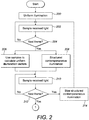
- the first optical source 142 therefore emits a first uniform continuous wave optical signal that illuminates (Step 200) a scene, for example the whole of the scene.
- the first optical source 142 is a source of unstructured light.
- An object in the scene for example, reflects the emitted first optical signal.
- the first optical source 142 illuminates the scene during a plurality of consecutive time frames.
- the phase signal generator 112 During the measurement time frame of the plurality of consecutive time frames, the phase signal generator 112 generates a continuous wave electrical signal, the timing control unit 118 controlling cycling through the set of phases in respect of the electrical signal relative to the continuous wave first optical signal.
- a synchronisation signal is also applied by timing control unit 118 to the frame buffer unit 110 to ensure transfer of complete sets of signals to the DFT unit 116.
- a multipath calculation activation signal is also provided by the timing control unit 118 via the multipath calculation control port 132, to the range calculation unit 130 to calculate a compensated vector. This can be achieved, for example, by setting a flag that the multipath calculation unit 138 and the vector-to-range calculation unit 136 monitor.
- the electrical signal generated by the phase signal generator 112 is applied to the photonic mixer 106 and the phase angle of the electrical signal is cycled through the set of phase angles mentioned above during the measurement time frame and digital representations of the charges stored in the integrator 108 in respect of each phase angle of the set of phase angles are received by the frame buffer 110 in series (Steps 202 and 204).
- the integrator 108 provides a plurality of phase angle sample outputs in series representing respective accumulated charge levels for applied phase angle values in respect of the photonic mixer pixel device 102.
- the phase buffer 110 effectively performs a serial-to-parallel conversion of the electrical measurement signals originating from the integrator 108 once a set of phase angles has been cycled through and then provides m parallel output signals to the DFT unit 116.
- a subsequent measurement time frame constituting another time frame temporally about the selected time frame, follows the measurement time frame, during which in response to receipt of the m output signals, the DFT unit 116 generates (Step 206) a pair of I/Q output signals at the I/Q output 126 constituting a uniform illumination vector, S uniform , in respect of the fundamental frequency and having a first phase angle.
- the I/Q output signal is received by the range calculation unit 130 and stored temporarily in the vector buffer 140 pending the receipt of another pair of I/Q output signals in respect of the subsequent measurement time frame.
- the timing control unit 118 instructs the activation controller 152 to permit the second driver circuit 150 to receive the trigger signals in order to drive the second optical source 144, which as mentioned above is configured to emit a structured light pattern.
- the second optical source 144 projects a high spatial frequency low intensity illumination pattern, for example a dot pattern generated by a Vertical Cavity Surface Emitting Laser (VCSEL) array placed in the focal plane of a lens, or a checkerboard pattern.
- VCSEL Vertical Cavity Surface Emitting Laser
- the second optical source 144 employs an illumination pattern comprising regions of no illumination.
- the structured light pattern is emitted (Step 208) contemporaneously with the uniform (non-structured) emission of light by the first optical source 142 during the subsequent measurement time frame and reflected by the object. It therefore follows that, in general terms, the second optical source 144 illuminates during predetermined frames of the plurality of consecutive time frames, which in this example are alternate time frames. However, the skilled person should appreciate that illumination by the second optical source 144 can, in other examples, occur after a predetermined number of time frames, repeatedly if required.
- the phase signal generator 112 When the second optical source 144 is illuminating the scene, the phase signal generator 112 still generates the continuous wave electrical signal as described above in relation to illumination by the first optical source alone, the timing control unit 118 controlling cycling through the set of phases in respect of the electrical signal relative to the continuous wave first optical signal.
- the electrical signal generated by the phase signal generator 112 is again applied to the photonic mixer 106 and the phase angle of the electrical signal is cycled through the set of phase angles mentioned above during the subsequent measurement time frame and digital representations of the charges stored in the integrator 108 in respect of each phase angle of the set of phase angles are received by the frame buffer 110 in series (Steps 210 and 212).
- the timing control unit 118 prevents (Step 214) the second driver circuit 150 from being triggered, which ceases emission of the second optical signal by the second optical source 144.
- the above-described process of illuminating with only uniform light by the first optical source 142 followed by combined illumination by first and second optical sources 142, 144 is repeated (Steps 200 to 214) along with calculation of associated vectors for as long as required.
- the phase buffer 110 again performs a serial-to-parallel conversion of the electrical measurement signals originating from the integrator 108 and provides the m parallel output signals to the DFT unit 116.
- the DFT unit 116 uses the m parallel output signals to generate (Step 216) a subsequent pair of I/Q output signals constituting a combined illumination vector, S both , in respect of the fundamental frequency and having a second phase angle.
- the subsequent I/Q output signal of the combined illumination vector, S both is received by the range calculation unit 130 and also stored in the vector buffer 140.
- each pixel 102 outputs a plurality of phase angle sample outputs, substantially in synchronism with the illumination of the scene by the second optical source 144 and/or the first optical source 142.
- the plurality of pixels generate a plurality of sets of signals substantially contemporaneously and the DFT unit 116 substantially contemporaneously generate the uniform illumination vectors, S uniform , and the combined illumination vectors, S both , at the appropriate times as already described above.
- a difference image frame is calculated between an image frame in respect of the plurality of sets of signals of the selected time frame (the measurement time frame in this example) and an image frame in respect of the plurality of sets of signals of the another time frame (the subsequent measurement time frame in this example).
- the multipath calculation unit 138 uses a priori knowledge of the pattern of the structured illumination of the second optical signal in order to identify (Step 220) non-illuminated areas of the pattern.
- estimation of the reflected light in respect of the non-illuminated areas of the pattern is by way of a low pass filtering operation, which is performed by the multipath calculation unit 138.
- the multipath calculation unit 138 uses the function (in this example the low-pass filtering function) to determine the error estimate for all vectors of the difference image frame and then to calculate (Step 222) "ground truth" vectors, S gt , representing the measured reflection from the object after compensation for estimated multipath errors:
- S ⁇ gt S ⁇ uniform ⁇ k ⁇ f S ⁇ mp
- k is a scaling constant defined by the optical power ratio between the first optical source 142 emitting the uniform optical signal and the second optical source 144 emitting the structured optical signal
- f( S mp ) is the calculated multipath error estimate across all the vectors of the difference image frame.
- the ground truth vectors, or corrected vectors, S gt are stored in the vector buffer 140.
- the error compensation vector k ⁇ f( S mp ) can be applied to both uniform illumination vectors, S uniform , and combined illumination vector S both .
- the compensated vectors calculated i.e. the ground truth vectors, S gt
- the vector-to-range calculation unit 136 is accessed by the vector-to-range calculation unit 136 and, in this example, the arctan unit of the vector-to-range calculation unit 136 calculates (Step 224) a phase angle defined by the ground truth vector, S gt , and thereafter a time of flight (Step 226) from the phase angle calculated using the indirect time of flight measurement technique and a predetermined scaling factor to translate the phase angle calculated to the time of flight. From the calculated time of flight, a range to the object is calculated.
- Steps 216 to 226) are repeated until generation of compensated measured ranges is no longer required. Consequently, the error estimates are, in this example, updated as required using the plurality of sets of signals generated during a selected time frame of the plurality of consecutive time frames subsequent to the subsequent measurement time frame, and using the plurality of sets of signals generated during a further time frame temporally about the subsequent selected time frame, illumination by the first optical source 142 occurring during the subsequent selected time frame and illumination by both the first and second optical sources 142, 144 occurring during the further time frame.
- phase buffer 110 and hence parallel processing of the buffered phase measurements obtained from the photonic mixer pixel device 102 in series can be omitted.
- serial transfer of the phase measurements can be directly to the DFT unit 116, thereby reducing memory requirements for the detection and ranging module.
- the DFT unit 116 can be provided with smaller internal buffers to calculate iteratively, for each frame cycle, intermediate I and Q values for the respective phase measurements received in series, which are accumulated over the frame cycle to generate final I and Q value results.
- the DFT unit 116 can be operably coupled to the timing control unit 118 to maintain synchronisation of data processing.
- the first optical source 142 illuminates uniformly over every measurement time frame and the second optical source 144 projects a high spatial frequency illumination pattern every other frame.
- a further optical source can be employed to project another pattern, for example a complementary pattern to the second optical source 144, to improve the multipath error compensation accuracy further, this additional pattern being emitted during a different time frame to the illumination projected by the second optical source 144, but contemporaneously with the uniform illumination by the first optical source 142.
- the illumination by the further optical source can occur during further predetermined frames of the plurality of consecutive time frames that are different from the predetermined frame mentioned above.
- a plurality of sets of signals can be generated respectively by the pixels during the further predetermined frames and the error estimate can be derived by using the plurality of sets of signals generated during another selected time frame of the further predetermined frames, illumination by the further optical source occurring during the another selected time frame.
- the structured light pattern emitted by the second optical source 144 is different from a further structured light pattern emitted by the further optical source.
- the above examples describe the generation of the plurality of uniform illumination vectors, S uniform , substantially contemporaneously during the measurement time frame, which can be understood to have been a selected time frame of the plurality of consecutive time frames for the purpose of making a measurement.
- the plurality of combined illumination vectors, S both are then generated in respect of the subsequent measurement time frame, which occurs immediately after the selected time frame.
- the plurality of combined illumination vectors, S both can be generated in respect of another time frame temporally about the selected time frame, illumination by the unstructured light source occurring during the selected time frame and illumination by both the structured and unstructured light sources occurring during the another time frame.
- the generation of the plurality of combined illumination vectors, S both does not have to take place immediately preceding or following the selected time frame and a larger number of time frames can be allowed, in some examples, to elapse after the selected time frame before the plurality of combined illumination vectors, S both , is generated, and/or a larger number of time frames can be allowed to elapse following the generation of the plurality of combined illumination vectors, S both , before the plurality of uniform illumination vectors, S uniform , is generated. It can therefore be seen that predetermined time frames during which the second optical source 144 illuminates the scene can be non-consecutive. Furthermore, the non-consecutive time frames can be regularly spaced in time.
- references herein to "light”, other than where expressly stated otherwise, are intended as references relating to the optical range of the electromagnetic spectrum, for example, between about 350 nm and about 2000 nm, such as between about 550 nm and about 1400 nm or between about 600 nm and about 1000 nm.
- Alternative embodiments of the invention can be implemented as a computer program product for use with a computer system, the computer program product being, for example, a series of computer instructions stored on a tangible data recording medium, such as a diskette, CD-ROM, ROM, or fixed disk, or embodied in a computer data signal, the signal being transmitted over a tangible medium or a wireless medium, for example, microwave or infrared.
- the series of computer instructions can constitute all or part of the functionality described above, and can also be stored in any memory device, volatile or non-volatile, such as semiconductor, magnetic, optical or other memory device.
Landscapes
- Physics & Mathematics (AREA)
- Engineering & Computer Science (AREA)
- Electromagnetism (AREA)
- General Physics & Mathematics (AREA)
- Computer Networks & Wireless Communication (AREA)
- Radar, Positioning & Navigation (AREA)
- Remote Sensing (AREA)
- Multimedia (AREA)
- Theoretical Computer Science (AREA)
- Computer Vision & Pattern Recognition (AREA)
- Optical Radar Systems And Details Thereof (AREA)
Priority Applications (3)
| Application Number | Priority Date | Filing Date | Title |
|---|---|---|---|
| EP19214971.4A EP3835720B1 (de) | 2019-12-10 | 2019-12-10 | Verfahren zur mehrpfadfehlerkompensation und vorrichtung zur mehrpfadfehlerkompensierten indirekten flugzeitberechnung |
| US17/116,061 US11802962B2 (en) | 2019-12-10 | 2020-12-09 | Method for multipath error compensation and multipath error-compensated indirect time of flight range calculation apparatus |
| CN202011434896.6A CN112946602A (zh) | 2019-12-10 | 2020-12-10 | 多路径误差补偿的方法和多路径误差补偿的间接飞行时间距离计算装置 |
Applications Claiming Priority (1)
| Application Number | Priority Date | Filing Date | Title |
|---|---|---|---|
| EP19214971.4A EP3835720B1 (de) | 2019-12-10 | 2019-12-10 | Verfahren zur mehrpfadfehlerkompensation und vorrichtung zur mehrpfadfehlerkompensierten indirekten flugzeitberechnung |
Publications (2)
| Publication Number | Publication Date |
|---|---|
| EP3835720A1 true EP3835720A1 (de) | 2021-06-16 |
| EP3835720B1 EP3835720B1 (de) | 2023-08-09 |
Family
ID=68848130
Family Applications (1)
| Application Number | Title | Priority Date | Filing Date |
|---|---|---|---|
| EP19214971.4A Active EP3835720B1 (de) | 2019-12-10 | 2019-12-10 | Verfahren zur mehrpfadfehlerkompensation und vorrichtung zur mehrpfadfehlerkompensierten indirekten flugzeitberechnung |
Country Status (3)
| Country | Link |
|---|---|
| US (1) | US11802962B2 (de) |
| EP (1) | EP3835720B1 (de) |
| CN (1) | CN112946602A (de) |
Families Citing this family (1)
| Publication number | Priority date | Publication date | Assignee | Title |
|---|---|---|---|---|
| CN113945951B (zh) * | 2021-10-21 | 2022-07-08 | 浙江大学 | Tof深度解算中的多径干扰抑制方法、tof深度解算方法及装置 |
Citations (8)
| Publication number | Priority date | Publication date | Assignee | Title |
|---|---|---|---|---|
| US20130148102A1 (en) | 2011-12-12 | 2013-06-13 | Mesa Imaging Ag | Method to Compensate for Errors in Time-of-Flight Range Cameras Caused by Multiple Reflections |
| US20150253429A1 (en) | 2014-03-06 | 2015-09-10 | University Of Waikato | Time of flight camera system which resolves direct and multi-path radiation components |
| US20180095165A1 (en) | 2016-09-30 | 2018-04-05 | Magic Leap, Inc. | Projector with spatial light modulation |
| US20180210070A1 (en) * | 2017-01-23 | 2018-07-26 | Microsoft Technology Licensing, Llc | Active Brightness-Based Strategy for Invalidating Pixels in Time-of-Flight Depth-Sensing |
| US10061028B2 (en) | 2013-09-05 | 2018-08-28 | Texas Instruments Incorporated | Time-of-flight (TOF) assisted structured light imaging |
| US20190051004A1 (en) | 2017-08-13 | 2019-02-14 | Shenzhen GOODIX Technology Co., Ltd. | 3d sensing technology based on multiple structured illumination |
| US20190068853A1 (en) | 2017-08-22 | 2019-02-28 | Microsoft Technology Licensing, Llc | Structured light and flood fill light illuminator |
| WO2019210431A1 (en) * | 2018-05-03 | 2019-11-07 | The Governing Council Of The University Of Toronto | Method and system for optimizing depth imaging |
Family Cites Families (2)
| Publication number | Priority date | Publication date | Assignee | Title |
|---|---|---|---|---|
| CN109906353B (zh) * | 2016-09-21 | 2021-06-15 | 飞利浦·M·约翰逊 | 采用混合循环二进制码结构光的非接触式坐标测量机 |
| US11609328B2 (en) * | 2018-05-23 | 2023-03-21 | Massachusetts Institute Of Technology | Methods and apparatus for improved imaging through scattering media |
-
2019
- 2019-12-10 EP EP19214971.4A patent/EP3835720B1/de active Active
-
2020
- 2020-12-09 US US17/116,061 patent/US11802962B2/en active Active
- 2020-12-10 CN CN202011434896.6A patent/CN112946602A/zh active Pending
Patent Citations (8)
| Publication number | Priority date | Publication date | Assignee | Title |
|---|---|---|---|---|
| US20130148102A1 (en) | 2011-12-12 | 2013-06-13 | Mesa Imaging Ag | Method to Compensate for Errors in Time-of-Flight Range Cameras Caused by Multiple Reflections |
| US10061028B2 (en) | 2013-09-05 | 2018-08-28 | Texas Instruments Incorporated | Time-of-flight (TOF) assisted structured light imaging |
| US20150253429A1 (en) | 2014-03-06 | 2015-09-10 | University Of Waikato | Time of flight camera system which resolves direct and multi-path radiation components |
| US20180095165A1 (en) | 2016-09-30 | 2018-04-05 | Magic Leap, Inc. | Projector with spatial light modulation |
| US20180210070A1 (en) * | 2017-01-23 | 2018-07-26 | Microsoft Technology Licensing, Llc | Active Brightness-Based Strategy for Invalidating Pixels in Time-of-Flight Depth-Sensing |
| US20190051004A1 (en) | 2017-08-13 | 2019-02-14 | Shenzhen GOODIX Technology Co., Ltd. | 3d sensing technology based on multiple structured illumination |
| US20190068853A1 (en) | 2017-08-22 | 2019-02-28 | Microsoft Technology Licensing, Llc | Structured light and flood fill light illuminator |
| WO2019210431A1 (en) * | 2018-05-03 | 2019-11-07 | The Governing Council Of The University Of Toronto | Method and system for optimizing depth imaging |
Also Published As
| Publication number | Publication date |
|---|---|
| CN112946602A (zh) | 2021-06-11 |
| EP3835720B1 (de) | 2023-08-09 |
| US20210173087A1 (en) | 2021-06-10 |
| US11802962B2 (en) | 2023-10-31 |
Similar Documents
| Publication | Publication Date | Title |
|---|---|---|
| EP3268771B1 (de) | Kohärentes ladar mit intra-pixel quadraturdetktion | |
| US9325920B2 (en) | Processing of time-of-flight signals | |
| US8786678B2 (en) | 3D time-of-flight camera and method | |
| US7800739B2 (en) | Distance measuring method and distance measuring element for detecting the spatial dimension of a target | |
| US10712432B2 (en) | Time-of-light-based systems using reduced illumination duty cycles | |
| US10473769B2 (en) | Distance measuring apparatus and distance image photographing apparatus | |
| EP3519854A1 (de) | Verfahren zur subtraktion des hintergrundlichts aus einem belichtungswert eines pixels in einem bildgebungsarray und pixel zur verwendung darin | |
| JP2021510417A (ja) | 階層化されたパワー制御によるlidarベースの距離測定 | |
| EP3370079B1 (de) | Bereichs- und parameterextraktion mit verarbeiteten histogrammen, die aus einer flugzeitsensorimpulskorrektur erzeugt sind | |
| EP2264481A1 (de) | Verfahren und Vorrichtung zum Erzeugen eines entfernungsaufgelösten Bildes | |
| WO2020047248A1 (en) | Glare mitigation in lidar applications | |
| KR20110085785A (ko) | 거리 정보 추출 방법 및 상기 방법을 채용한 광학 장치 | |
| JP6261681B2 (ja) | タイムオブフライト信号の処理における又はこれに関する改良 | |
| US11393115B2 (en) | Filtering continuous-wave time-of-flight measurements, based on coded modulation images | |
| EP3956689A1 (de) | Flugzeitmessungen mittels linearer inverser funktion | |
| CN112601972A (zh) | 通过无模糊范围切换增大飞行时间系统范围的方法及系统 | |
| US20220252730A1 (en) | Time-of-flight imaging apparatus and time-of-flight imaging method | |
| EP3835819A1 (de) | Vorrichtung zur berechnung eines optischen bereichs und verfahren zur berechnung eines optischen bereichs | |
| US20220018764A1 (en) | Method for determining the distance and reflectivity of an object surface | |
| EP2275833A1 (de) | Entfernungskamera und Entfernungsbildaufnahmeverfahren | |
| US11802962B2 (en) | Method for multipath error compensation and multipath error-compensated indirect time of flight range calculation apparatus | |
| US11971505B2 (en) | Methods and devices for peak signal detection | |
| Hussmann et al. | Investigation of different polar to Cartesian coordinate system conversion methods for ToF-cameras in the close-up range | |
| US20210364612A1 (en) | Method of optical detection and optical detection apparatus | |
| WO2019054917A1 (en) | LIDAR OF SCHEIMPFLUG FLIGHT TIME |
Legal Events
| Date | Code | Title | Description |
|---|---|---|---|
| PUAI | Public reference made under article 153(3) epc to a published international application that has entered the european phase |
Free format text: ORIGINAL CODE: 0009012 |
|
| STAA | Information on the status of an ep patent application or granted ep patent |
Free format text: STATUS: THE APPLICATION HAS BEEN PUBLISHED |
|
| AK | Designated contracting states |
Kind code of ref document: A1 Designated state(s): AL AT BE BG CH CY CZ DE DK EE ES FI FR GB GR HR HU IE IS IT LI LT LU LV MC MK MT NL NO PL PT RO RS SE SI SK SM TR |
|
| STAA | Information on the status of an ep patent application or granted ep patent |
Free format text: STATUS: REQUEST FOR EXAMINATION WAS MADE |
|
| 17P | Request for examination filed |
Effective date: 20211125 |
|
| RBV | Designated contracting states (corrected) |
Designated state(s): AL AT BE BG CH CY CZ DE DK EE ES FI FR GB GR HR HU IE IS IT LI LT LU LV MC MK MT NL NO PL PT RO RS SE SI SK SM TR |
|
| RIC1 | Information provided on ipc code assigned before grant |
Ipc: G01S 17/894 20200101ALI20230104BHEP Ipc: G01S 17/32 19800101ALI20230104BHEP Ipc: G01S 17/46 19800101ALI20230104BHEP Ipc: G01B 11/25 20000101AFI20230104BHEP |
|
| GRAP | Despatch of communication of intention to grant a patent |
Free format text: ORIGINAL CODE: EPIDOSNIGR1 |
|
| STAA | Information on the status of an ep patent application or granted ep patent |
Free format text: STATUS: GRANT OF PATENT IS INTENDED |
|
| INTG | Intention to grant announced |
Effective date: 20230301 |
|
| GRAS | Grant fee paid |
Free format text: ORIGINAL CODE: EPIDOSNIGR3 |
|
| GRAA | (expected) grant |
Free format text: ORIGINAL CODE: 0009210 |
|
| STAA | Information on the status of an ep patent application or granted ep patent |
Free format text: STATUS: THE PATENT HAS BEEN GRANTED |
|
| AK | Designated contracting states |
Kind code of ref document: B1 Designated state(s): AL AT BE BG CH CY CZ DE DK EE ES FI FR GB GR HR HU IE IS IT LI LT LU LV MC MK MT NL NO PL PT RO RS SE SI SK SM TR |
|
| REG | Reference to a national code |
Ref country code: GB Ref legal event code: FG4D |
|
| REG | Reference to a national code |
Ref country code: CH Ref legal event code: EP |
|
| REG | Reference to a national code |
Ref country code: IE Ref legal event code: FG4D |
|
| REG | Reference to a national code |
Ref country code: DE Ref legal event code: R096 Ref document number: 602019034482 Country of ref document: DE |
|
| REG | Reference to a national code |
Ref country code: LT Ref legal event code: MG9D |
|
| REG | Reference to a national code |
Ref country code: NL Ref legal event code: MP Effective date: 20230809 |
|
| REG | Reference to a national code |
Ref country code: AT Ref legal event code: MK05 Ref document number: 1597996 Country of ref document: AT Kind code of ref document: T Effective date: 20230809 |
|
| PG25 | Lapsed in a contracting state [announced via postgrant information from national office to epo] |
Ref country code: GR Free format text: LAPSE BECAUSE OF FAILURE TO SUBMIT A TRANSLATION OF THE DESCRIPTION OR TO PAY THE FEE WITHIN THE PRESCRIBED TIME-LIMIT Effective date: 20231110 |
|
| PG25 | Lapsed in a contracting state [announced via postgrant information from national office to epo] |
Ref country code: IS Free format text: LAPSE BECAUSE OF FAILURE TO SUBMIT A TRANSLATION OF THE DESCRIPTION OR TO PAY THE FEE WITHIN THE PRESCRIBED TIME-LIMIT Effective date: 20231209 |
|
| PG25 | Lapsed in a contracting state [announced via postgrant information from national office to epo] |
Ref country code: SE Free format text: LAPSE BECAUSE OF FAILURE TO SUBMIT A TRANSLATION OF THE DESCRIPTION OR TO PAY THE FEE WITHIN THE PRESCRIBED TIME-LIMIT Effective date: 20230809 Ref country code: RS Free format text: LAPSE BECAUSE OF FAILURE TO SUBMIT A TRANSLATION OF THE DESCRIPTION OR TO PAY THE FEE WITHIN THE PRESCRIBED TIME-LIMIT Effective date: 20230809 Ref country code: PT Free format text: LAPSE BECAUSE OF FAILURE TO SUBMIT A TRANSLATION OF THE DESCRIPTION OR TO PAY THE FEE WITHIN THE PRESCRIBED TIME-LIMIT Effective date: 20231211 Ref country code: NO Free format text: LAPSE BECAUSE OF FAILURE TO SUBMIT A TRANSLATION OF THE DESCRIPTION OR TO PAY THE FEE WITHIN THE PRESCRIBED TIME-LIMIT Effective date: 20231109 Ref country code: NL Free format text: LAPSE BECAUSE OF FAILURE TO SUBMIT A TRANSLATION OF THE DESCRIPTION OR TO PAY THE FEE WITHIN THE PRESCRIBED TIME-LIMIT Effective date: 20230809 Ref country code: LV Free format text: LAPSE BECAUSE OF FAILURE TO SUBMIT A TRANSLATION OF THE DESCRIPTION OR TO PAY THE FEE WITHIN THE PRESCRIBED TIME-LIMIT Effective date: 20230809 Ref country code: LT Free format text: LAPSE BECAUSE OF FAILURE TO SUBMIT A TRANSLATION OF THE DESCRIPTION OR TO PAY THE FEE WITHIN THE PRESCRIBED TIME-LIMIT Effective date: 20230809 Ref country code: IS Free format text: LAPSE BECAUSE OF FAILURE TO SUBMIT A TRANSLATION OF THE DESCRIPTION OR TO PAY THE FEE WITHIN THE PRESCRIBED TIME-LIMIT Effective date: 20231209 Ref country code: HR Free format text: LAPSE BECAUSE OF FAILURE TO SUBMIT A TRANSLATION OF THE DESCRIPTION OR TO PAY THE FEE WITHIN THE PRESCRIBED TIME-LIMIT Effective date: 20230809 Ref country code: GR Free format text: LAPSE BECAUSE OF FAILURE TO SUBMIT A TRANSLATION OF THE DESCRIPTION OR TO PAY THE FEE WITHIN THE PRESCRIBED TIME-LIMIT Effective date: 20231110 Ref country code: FI Free format text: LAPSE BECAUSE OF FAILURE TO SUBMIT A TRANSLATION OF THE DESCRIPTION OR TO PAY THE FEE WITHIN THE PRESCRIBED TIME-LIMIT Effective date: 20230809 Ref country code: AT Free format text: LAPSE BECAUSE OF FAILURE TO SUBMIT A TRANSLATION OF THE DESCRIPTION OR TO PAY THE FEE WITHIN THE PRESCRIBED TIME-LIMIT Effective date: 20230809 |
|
| PGFP | Annual fee paid to national office [announced via postgrant information from national office to epo] |
Ref country code: FR Payment date: 20231122 Year of fee payment: 5 Ref country code: DE Payment date: 20231121 Year of fee payment: 5 |
|
| PG25 | Lapsed in a contracting state [announced via postgrant information from national office to epo] |
Ref country code: PL Free format text: LAPSE BECAUSE OF FAILURE TO SUBMIT A TRANSLATION OF THE DESCRIPTION OR TO PAY THE FEE WITHIN THE PRESCRIBED TIME-LIMIT Effective date: 20230809 |
|
| P01 | Opt-out of the competence of the unified patent court (upc) registered |
Effective date: 20240319 |
|
| PG25 | Lapsed in a contracting state [announced via postgrant information from national office to epo] |
Ref country code: ES Free format text: LAPSE BECAUSE OF FAILURE TO SUBMIT A TRANSLATION OF THE DESCRIPTION OR TO PAY THE FEE WITHIN THE PRESCRIBED TIME-LIMIT Effective date: 20230809 |
|
| PG25 | Lapsed in a contracting state [announced via postgrant information from national office to epo] |
Ref country code: SM Free format text: LAPSE BECAUSE OF FAILURE TO SUBMIT A TRANSLATION OF THE DESCRIPTION OR TO PAY THE FEE WITHIN THE PRESCRIBED TIME-LIMIT Effective date: 20230809 Ref country code: RO Free format text: LAPSE BECAUSE OF FAILURE TO SUBMIT A TRANSLATION OF THE DESCRIPTION OR TO PAY THE FEE WITHIN THE PRESCRIBED TIME-LIMIT Effective date: 20230809 Ref country code: ES Free format text: LAPSE BECAUSE OF FAILURE TO SUBMIT A TRANSLATION OF THE DESCRIPTION OR TO PAY THE FEE WITHIN THE PRESCRIBED TIME-LIMIT Effective date: 20230809 Ref country code: EE Free format text: LAPSE BECAUSE OF FAILURE TO SUBMIT A TRANSLATION OF THE DESCRIPTION OR TO PAY THE FEE WITHIN THE PRESCRIBED TIME-LIMIT Effective date: 20230809 Ref country code: DK Free format text: LAPSE BECAUSE OF FAILURE TO SUBMIT A TRANSLATION OF THE DESCRIPTION OR TO PAY THE FEE WITHIN THE PRESCRIBED TIME-LIMIT Effective date: 20230809 Ref country code: CZ Free format text: LAPSE BECAUSE OF FAILURE TO SUBMIT A TRANSLATION OF THE DESCRIPTION OR TO PAY THE FEE WITHIN THE PRESCRIBED TIME-LIMIT Effective date: 20230809 Ref country code: SK Free format text: LAPSE BECAUSE OF FAILURE TO SUBMIT A TRANSLATION OF THE DESCRIPTION OR TO PAY THE FEE WITHIN THE PRESCRIBED TIME-LIMIT Effective date: 20230809 |
|
| REG | Reference to a national code |
Ref country code: DE Ref legal event code: R097 Ref document number: 602019034482 Country of ref document: DE |
|
| PG25 | Lapsed in a contracting state [announced via postgrant information from national office to epo] |
Ref country code: IT Free format text: LAPSE BECAUSE OF FAILURE TO SUBMIT A TRANSLATION OF THE DESCRIPTION OR TO PAY THE FEE WITHIN THE PRESCRIBED TIME-LIMIT Effective date: 20230809 |
|
| PLBE | No opposition filed within time limit |
Free format text: ORIGINAL CODE: 0009261 |
|
| STAA | Information on the status of an ep patent application or granted ep patent |
Free format text: STATUS: NO OPPOSITION FILED WITHIN TIME LIMIT |
|
| 26N | No opposition filed |
Effective date: 20240513 |
|
| PG25 | Lapsed in a contracting state [announced via postgrant information from national office to epo] |
Ref country code: SI Free format text: LAPSE BECAUSE OF FAILURE TO SUBMIT A TRANSLATION OF THE DESCRIPTION OR TO PAY THE FEE WITHIN THE PRESCRIBED TIME-LIMIT Effective date: 20230809 |
|
| REG | Reference to a national code |
Ref country code: CH Ref legal event code: PL |
|
| PG25 | Lapsed in a contracting state [announced via postgrant information from national office to epo] |
Ref country code: LU Free format text: LAPSE BECAUSE OF NON-PAYMENT OF DUE FEES Effective date: 20231210 |
|
| PG25 | Lapsed in a contracting state [announced via postgrant information from national office to epo] |
Ref country code: MC Free format text: LAPSE BECAUSE OF FAILURE TO SUBMIT A TRANSLATION OF THE DESCRIPTION OR TO PAY THE FEE WITHIN THE PRESCRIBED TIME-LIMIT Effective date: 20230809 |
|
| GBPC | Gb: european patent ceased through non-payment of renewal fee |
Effective date: 20231210 |
|
| REG | Reference to a national code |
Ref country code: BE Ref legal event code: MM Effective date: 20231231 |
|
| PG25 | Lapsed in a contracting state [announced via postgrant information from national office to epo] |
Ref country code: MC Free format text: LAPSE BECAUSE OF FAILURE TO SUBMIT A TRANSLATION OF THE DESCRIPTION OR TO PAY THE FEE WITHIN THE PRESCRIBED TIME-LIMIT Effective date: 20230809 Ref country code: LU Free format text: LAPSE BECAUSE OF NON-PAYMENT OF DUE FEES Effective date: 20231210 |