EP3835691A1 - Lid for a cooling box - Google Patents
Lid for a cooling box Download PDFInfo
- Publication number
- EP3835691A1 EP3835691A1 EP19215376.5A EP19215376A EP3835691A1 EP 3835691 A1 EP3835691 A1 EP 3835691A1 EP 19215376 A EP19215376 A EP 19215376A EP 3835691 A1 EP3835691 A1 EP 3835691A1
- Authority
- EP
- European Patent Office
- Prior art keywords
- filling
- lid
- coolant
- cooling
- compartment
- Prior art date
- Legal status (The legal status is an assumption and is not a legal conclusion. Google has not performed a legal analysis and makes no representation as to the accuracy of the status listed.)
- Withdrawn
Links
- 238000001816 cooling Methods 0.000 title claims abstract description 129
- 239000002826 coolant Substances 0.000 claims abstract description 181
- 239000008188 pellet Substances 0.000 claims abstract description 57
- 238000000034 method Methods 0.000 claims description 31
- 239000010902 straw Substances 0.000 claims description 15
- 239000004745 nonwoven fabric Substances 0.000 claims description 8
- 239000003292 glue Substances 0.000 claims description 4
- CURLTUGMZLYLDI-UHFFFAOYSA-N Carbon dioxide Chemical compound O=C=O CURLTUGMZLYLDI-UHFFFAOYSA-N 0.000 abstract description 22
- 235000011089 carbon dioxide Nutrition 0.000 abstract description 14
- 239000004033 plastic Substances 0.000 abstract description 11
- 235000013305 food Nutrition 0.000 abstract description 5
- 239000013502 plastic waste Substances 0.000 abstract description 4
- 238000009434 installation Methods 0.000 description 9
- 239000007787 solid Substances 0.000 description 5
- 239000004793 Polystyrene Substances 0.000 description 4
- 229910002092 carbon dioxide Inorganic materials 0.000 description 4
- 239000001569 carbon dioxide Substances 0.000 description 4
- 229920002223 polystyrene Polymers 0.000 description 4
- 230000005484 gravity Effects 0.000 description 3
- 239000000463 material Substances 0.000 description 3
- 238000005303 weighing Methods 0.000 description 3
- 230000015572 biosynthetic process Effects 0.000 description 2
- 238000010586 diagram Methods 0.000 description 2
- 238000009826 distribution Methods 0.000 description 2
- 238000005429 filling process Methods 0.000 description 2
- 239000002184 metal Substances 0.000 description 2
- 230000003213 activating effect Effects 0.000 description 1
- 230000001419 dependent effect Effects 0.000 description 1
- 238000003825 pressing Methods 0.000 description 1
- 230000002441 reversible effect Effects 0.000 description 1
Images


Classifications
-
- F—MECHANICAL ENGINEERING; LIGHTING; HEATING; WEAPONS; BLASTING
- F25—REFRIGERATION OR COOLING; COMBINED HEATING AND REFRIGERATION SYSTEMS; HEAT PUMP SYSTEMS; MANUFACTURE OR STORAGE OF ICE; LIQUEFACTION SOLIDIFICATION OF GASES
- F25D—REFRIGERATORS; COLD ROOMS; ICE-BOXES; COOLING OR FREEZING APPARATUS NOT OTHERWISE PROVIDED FOR
- F25D3/00—Devices using other cold materials; Devices using cold-storage bodies
- F25D3/12—Devices using other cold materials; Devices using cold-storage bodies using solidified gases, e.g. carbon-dioxide snow
- F25D3/14—Devices using other cold materials; Devices using cold-storage bodies using solidified gases, e.g. carbon-dioxide snow portable, i.e. adapted to be carried personally
Definitions
- the present invention is directed to a lid for a cooling box and to a respective cooling box as well as to a method for filling a coolant into the lid and a respective filling device.
- the cooling box can be used, in particular, to deliver fresh food products ordered online by final customers.
- cooling is achieved in a passive manner such that the cooling box does not have to be connected to an external power supply.
- cooling boxes are known that can be cooled with cool packs and/or ice.
- cooling can be achieved by dry ice.
- plastic bags filled with dry ice are placed into the cooling box. This is convenient because a contact between the dry ice and the products can be avoided due to the plastic bags.
- the plastic bags can be filled with such an amount of dry ice that is adapted to a scheduled duration of a delivery tour.
- this method produces a significant amount of plastic waste.
- the plastic bags reduce the space within the cooling box. Further, a device is required for filling the plastic bags with dry ice.
- an object of the present invention to overcome at least in part the disadvantages known from prior art and, in particular, to provide a cooling box that can be cooled in a particularly efficient manner. Also, a lid for such a cooling box as well as a method for filling a coolant into the lid and a respective filling device are supposed to be presented.
- a lid for a cooling box comprises:
- the described lid can be used to close the cooling box.
- the cooling box is used in the context of the so-called e-commerce, wherein customers order, in particular, food products online.
- the cooling box can be cooled with the described lid. Thereby, it can be ensured that the cold chain is not interrupted.
- the cooling box preferably comprises a container with a cooling chamber.
- the products that are supposed to be cooled can be placed into the cooling chamber.
- the cooling chamber has an opening, via which the products can be placed into the cooling chamber and can be taken out of the cooling chamber.
- the container has a cuboid shape, wherein a respective wall is arranged on five sides of the container, and wherein the opening is formed at the remaining sixth side.
- the opening can be closed by the described lid. Accordingly, it is preferred that the lid is configured for closing and opening the cooling chamber of the cooling box.
- the lid comprises a coolant compartment that is supposed to be filled with a coolant.
- the coolant is dry ice.
- Dry ice as used herein, is solid carbon dioxide.
- the coolant is preferably provided in the form of coolant pellets, in particular in the form of dry ice pellets. Coolant pellets are bodies of the coolant having a size of less than 5 mm in every direction. Alternatively, coolant snow can be used, in particular dry ice snow.
- the lid has a cooling side.
- the lid is configured such that the cooling side is cooled by the coolant within the coolant compartment. That is, cold generated by the coolant can be emitted by the lid via the cooling side. It is preferred that the lid is thermally isolated to all sides other than the cooling side. Thus, the cold generated by the coolant can leave the lid only towards the cooling chamber covered by the lid.
- the housing is preferably made of a thermally isolating material such as polystyrene. Alternatively, straw can be used, in particular compressed straw.
- the coolant compartment is formed within the housing of the lid.
- the lid has a cuboid shape.
- the cooling side is one of the sides of the cuboid.
- the housing comprises a base plate opposite the cooling side and four side walls. That is, the coolant compartment is confined by the housing at least to five sides. At the remaining side, which is the cooling side, the coolant compartment is confined at least in a gas permeable manner. That means that gas can move out of the coolant compartment or into the coolant compartment via the cooling side.
- all other sides of the coolant compartment are configured in a gas tight manner. Thus, a gas exchange between the coolant compartment and an outside of the lid is only possible via the cooling side. If the lid is attached to a cooling box, the coolant compartment can exchange gas only with the cooling chamber of the cooling box.
- the coolant compartment is preferably confined in a solid impermeable manner to all sides. Thus, a solid coolant cannot leave the coolant compartment. Also, the coolant compartment is preferably confined in a gas impermeable manner to all sided except the cooling side. Thus, a cold gas generated from the coolant can leave the coolant compartment via the cooling side only.
- the coolant within the coolant compartment sublimates over time. Thereby, cold carbon dioxide gas is generated. This gas can leave the coolant compartment via the cooling side. If the lid is attached to a cooling box, the cold carbon dioxide gas can enter the cooling chamber of the cooling box. Thereby, the cooling chamber can be cooled.
- the cooling side is gas permeable
- the coolant compartment can have an opening that extends across the cooling side entirely or partly, wherein a gas permeable element covers the opening.
- the coolant compartment can be closed at the cooling side except for gas channels connecting the coolant compartment to the outside of the lid.
- the gas channels preferably have such a small diameter that no solid bodies can leave the coolant compartment via the gas channels.
- the minimal cross section of each of the channels is less than 0.5 cm 2 , in particular less than 0. 1 cm 2 .
- the coolant can be introduced into the coolant compartment via the filling port.
- the filling port preferably comprises a hole that extends through the housing such as to connect the coolant compartment with the outside of the lid.
- the filling port further comprises the unidirectional valve.
- the unidirectional valve is configured such that, by default, the filling port is closed by the unidirectional valve.
- the term "default" refers to a state in which no external force affects the unidirectional valve. By means of such an external force the unidirectional valve can be opened. However, the unidirectional valve can only be opened by a force that is directed towards the coolant compartment, not by a force that is directed out of the coolant compartment.
- the unidirectional valve can be opened by a coolant flow directed into the coolant compartment, but not by a coolant flow directed out of the coolant compartment.
- the unidirectional valve can be opened manually from the outside of the lid, for example by pressing a filling pipe against the unidirectional valve. It is possible to open the unidirectional valve by applying an external force to the unidirectional valve in the direction in which the unidirectional valve opens and to allow a coolant flow in the opposite direction. Although this is not reasonable, the possibility of doing so is mentioned here in order to clarify that the term "unidirectional" does not necessarily refer to a flow direction through the valve, but rather to the direction of the external force that can open the unidirectional valve.
- the coolant will flow through the unidirectional valve only in the direction in which an external force can open the unidirectional valve, that is into the coolant compartment.
- the unidirectional valve could also be referred to as a check valve or a non-return valve.
- the coolant can be filled into the coolant compartment and can be confined therein. There is no need to open the filling port manually prior to filling and/or to close the filling port manually after filling. This facilitates the filling process.
- providing the coolant within the lid of a cooling box is competitively viable compared to using plastic bags filled with the coolant. There is no longer a need to use plastic bags, such that plastic waste can be avoided.
- the coolant compartment has, at the cooling side of the lid, an opening that is covered by a gas permeable nonwoven fabric.
- the housing has a cuboid shape and confines the coolant compartment to all sides except for the cooling side. At the cooling side the coolant compartment has the opening. In order to have the coolant compartment confined to all sides, the opening is covered by the gas permeable nonwoven fabric.
- the unidirectional valve comprises a flap that, by default, seals the filling port and that can be bent towards the coolant compartment so as to open the filling port.
- the flap is arranged within the coolant compartment.
- the flap is preferably made of a plastic material or of a metal.
- the flap is preferably attached to the housing, in particular to a side wall thereof. If the filling port is comprises a hole that extends through the housing, the flap is preferably dimensioned and arranged so as to cover this hole by default. The filling port is thus sealed by the flap.
- the term "default" refers to a state of the flap in which no external force acts upon the flap. In this state, the flap is preferably configured in a straight manner. The flap can be bent by an external force so as to be brought out of the default state. Thereby, the filling port can be opened.
- An external force can be applied to the flap by a coolant flow and/or by a filling pipe.
- the flap is arranged and configured such that the flap can be bent only if the external force is directed towards the coolant compartment, but not if the external force is directed out of the coolant compartment. That is, a coolant flow can bend the flap only if directed into the coolant compartment. The coolant cannot flow out of the coolant compartment. Also, the flap can be bent by contacting the flap with a filling pipe from the outside of the lid.
- the flap is configured in an elastic manner so that the flap generates a resilient force for restoring the default state. This can be achieved, for example, if the flap is made of a plastic material or of a flexible metal.
- the housing comprises a base plate that confines the coolant compartment opposite to the cooling side, wherein the base plate is made of straw, in particular of compressed straw.
- the cooling side and the base plate are arranged on two opposite sides of the cuboid, whereas the four remaining sides are formed by a respective side wall.
- cooling boxes made of compressed straw are known. Straw has the advantage of being economically friendly, in particular compared to polystyrene.
- Such cooling boxes can comprise a container and a lid, each being made of compressed straw.
- the lid has no coolant compartment.
- side walls and a nonwoven fabric can be added so as to form a coolant compartment.
- a lid according to the present embodiment is obtained, wherein only the base plate is made of compressed straw.
- the side walls can be made of, for example, polystyrene or straw, in particular compressed straw.
- the housing comprises a side wall transversal to the cooling side, wherein the base plate is attached to the side wall by a glue connection, a screw connection or a clamping connection.
- the fact that the side wall is arranged transversal to the front side means that the side wall encloses an angle with the front side, in particular of 90°.
- the lid can comprise one or several side walls.
- a single side wall having the shape of a circular cylinder jacket can be used.
- four side walls can be used that, together, have the shape of a rectangular cylinder jacket. In the latter case, the four side walls could also be considered a single side wall.
- the coolant compartment is preferably confined to all sides except for the cooling side.
- the coolant compartment is preferably confined by nonwoven fabric.
- the nonwoven fabric can be attached to the side wall(s) so as to cover an opening formed by the side wall(s).
- the lid can be obtained in a particularly simple manner form the previously described known cooling box made of compressed straw. Therefore, the straw lid is used as the base plate and the side wall is attached thereto by the glue connection, by the screw connection and/or by the clamping connection.
- the screw connection is preferably realized by means of one or more polystyrene screws.
- the clamping connection is preferred because it can be established and released particularly easily and in a reversible manner.
- the housing comprises a side wall transversal to the cooling side, wherein the filling port is arranged at the side wall.
- the filling port is arranged at the side of the lid. That is, the coolant can be filled into the coolant compartment form the side of the lid. This facilitates the filling of the coolant into the coolant compartment because the lid can be oriented such that the filling port is at the top. That means that there is no other orientation of the lid in which the filling port would be at a higher position relative to the rest of the lid. If the filling port is situated at the top, the coolant can be filled into the coolant compartment using gravity. Also, gravity does not cause an undesired counterflow of the coolant.
- a cooling box that comprises:
- the cooling box is preferably configured for transporting goods that are supposed to be cooled during transport.
- the goods can be stored within the cooling chamber. Cooling is achieved by means of the lid, in particular due to the coolant provided within the coolant compartment thereof.
- the fact that the opening of the cooling chamber can be covered by the lid such that the cooling side of the lid faces the cooling chamber means that the container and the lid are configured in a way that if used as intended, the cooling side faces the cooling chamber when the lid covers the opening of the cooling chamber.
- the container and the lid correspond to each other such that there is a limited number of distinct possibilities to close the opening of the cooling chamber with the lid.
- the lid and/or the cooling box are symmetrical such that the lid can be placed onto the opening of the cooling chamber in two equivalent orientations that differ by a 180° rotation of the lid relative to the cooling chamber.
- a method for filling coolant pellets into a lid for a cooling box comprising:
- the described method is preferably used to fill coolant pellets into the described lid.
- the described lid is preferably configured to be filled with coolant pellets by the described method.
- step a) the coolant pellets are provided. Therefore, the coolant pellets can be obtained prior to the beginning of the described method. Alternatively, the coolant pellets can be obtained as part of the described method in step a). Preferably, the coolant pellets are provided such that the coolant pellets can be dispensed from a filling pipe.
- step b) the filling pipe is used to open the unidirectional valve. That is, by means of the filling pipe an external force is applied to the unidirectional valve. If the unidirectional valve comprises a flap, the flap can be bent by the filling pipe. Thereby, the filling port is opened in step b).
- step c) the coolant pellets are filled into the coolant compartment. Therefore, the coolant pellets are dispensed from the filling pipe and are guided through the filling port and into the coolant compartment.
- step b) the lid is lifted and the filling pipe is maintained stationary.
- Maintaining the filling pipe in a stationary manner is advantageous because there is no need for the filling pipe to comprise any movable elements.
- the lid can be lifted, in particular, by means of a cam wheel.
- step c) the lid is oriented with the filling port at the top.
- the coolant pellets can be filled into the coolant compartment using gravity. A means for driving the coolant pellets is not required.
- step c) the lid is moved up and down repeatedly.
- the coolant pellets By moving the lid, the coolant pellets can be distributed particularly well within the coolant compartment.
- the formation of coolant blocks can be avoided. This is advantageous because coolant blocks could lead to a non-uniform cooling.
- the lid can be moved up and down, in particular, by means of the same cam wheel that is also used to lift the lid in step b).
- the up and down movement of the lid can also be considered a shaking of the lid.
- a filling device for filling coolant pellets into lids for cooling boxes.
- the lids comprise a respective filling port for filling the coolant pellets into a respective coolant compartment of the lid.
- the filling device comprises:
- the lid, the cooling box and the method can be applied to the filling device, and vice versa. It is preferred that the described lid is filled using the filling device, in particular by the described method.
- the filling device is preferably configured for filling the described lid, in particular by means of the described method.
- each lid is supposed to be used for a respective cooling box.
- the cooling chambers can be filled with the products. This saves time because the two processes can be performed independently of each other at the same time.
- the coolant supply unit is preferably configured for providing the coolant pellets, in particular according to step a) of the described method.
- the coolant supply unit is configured such that the coolant pellets can be dispensed from a filling pipe of the coolant supply unit, in particular according to step c) of the described method.
- the lids can be moved to the filling pipe by means of the conveyor.
- the conveyor can convey multiple lids simultaneously. One after the other can be brought into the filling position and can be filled with the coolant pellets.
- the conveyor is clocked based on the time for filling each of the lids.
- the lids are preferably arranged at the conveyor such that the respective filling port is at the top.
- the conveyor is arranged below the filling pipe and the filling pipe has a filling end that faces downwards, that is towards the conveyor.
- the filling end of the filling pipe is the end of the filling pipe at which the coolant pellets are dispensed from the filling pipe.
- a lid is moved by the conveyor into the filling position, this lid can be filled with the coolant pellets. Therefore, the respective lid is lifted by the lifting means such that the filling pipe is introduced into the filling port of the respective lid, in particular according to step b) of the described method.
- the filling pipe is stationary.
- the relative movement of the lid with respect to the filling pipe is obtained by lifting the lid.
- the lifting means is preferably embedded in the conveyor.
- the lifting means comprises a cam wheel.
- the cam wheel is preferably configured as a part of the conveyor.
- the lids can be brought into the filling position, one after the other, where the respective lid can be lifted by activating the cam wheel.
- the lifting means comprises guides that guide the lifting movement of the lid.
- the cam wheel can also be used to move the lid up and down in step c).
- the conveyor comprises a respective holder for multiple of the lids.
- the holder is configured such that the lid can be lifted therein. In that case it is not necessary that the lifting installation comprises guides for the lid.
- the filling pipe has at least one lateral nozzle opening.
- lateral nozzle openings the coolant pellets can be ejected from the filling pipe perpendicular to the filling pipe. This was found to enhance the distribution of the coolant pellets within the coolant compartment and to reduce the risk of coolant block formation. This is due to the fact that by means of the lateral nozzle openings a straight stream of coolant pellets is avoided. If several nozzle openings are provided, fewer coolant pellets leave each nozzle such that the distribution of the coolant pellets is further enhanced.
- the filling pipe has two lateral nozzle openings that are preferably arranged at the filling end on opposite sides of the filling pipe.
- Fig. 1 shows a cooling box 1 comprising a container 2 with a cooling chamber 14 having an opening 15. Further, the cooling box 1 comprises a lid 3 with a cooling side 6. By means of the lid 3 the opening 15 of the cooling chamber 14 can be covered such that the cooling side 6 of the lid 3 faces the cooling chamber 14.
- the cooling box 1 and the lid 3 have a respective cuboid shape.
- Fig. 2 is a sectional side view of the lid 3 of the cooling box 1 of Fig. 1 .
- the lid 3 comprises a housing 4 with a coolant compartment 5 that is confined in a gas permeable manner at the cooling side 6. Further, the lid 3 comprises a filling port 7 for filling a coolant into the coolant compartment 5.
- the filling port 7 comprises a unidirectional valve 8 that can be opened towards the coolant compartment 5.
- the unidirectional valve 8 comprises a flap 11 that, by default, seals the filling port 7 (as indicated by a solid line) and that can be bent towards the coolant compartment 5 so as to open the filling port 7 (as indicated by a dotted line).
- the housing 4 comprises a base plate 12 that confines the coolant compartment 5 opposite to the cooling side 6, that is at the top in the view of Fig. 2 .
- the base plate 12 can be made of straw, in particular of compressed straw.
- the housing 4 further comprises four side walls 13 (of which two are shown) transversal to the cooling side 6.
- the base plate 12 can be attached to the side walls 13 by a glue connection, a screw connection or a clamping connection.
- the filling port 7 is arranged at the side wall 13 on the left in Fig. 2 .
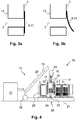
- Fig. 3a shows a first enlargement of Fig. 2 , wherein the flap 11 is shown in the default state in which the filling port 7 is sealed.
- Fig. 3b shows a second enlargement of Fig. 2 , wherein the flap 11 is shown in a bent state in which the filling port 7 is opened.
- Fig. 4 shows a side view of a filling device 18, by means of which lids 3 as shown in Fig. 1 can be filled with coolant pellets 16.
- the filling device 18 comprises a coolant supply unit 19.
- the coolant supply unit 19 comprises a pelletizer 27. That is a device for crushing blocks of a solid coolant such as dry ice into pellets.
- the coolant supply unit 19 comprises a dosing installation 29 and an auger 28, by means of which the coolant pellets 16 can be moved from the pelletizer 27 to the dosing installation 29.
- the dosing installation 29 the amount of the coolant pellets 16 that is supposed to be filled into a particular lid 3 can be separated. By means of a weighing means 30 this amount can be measured.
- the coolant pellets 16 can be filled into the lid 3 via a filling pipe 17 with a filling end 20 that faces downwards (shown in detail in Fig. 5 ). Therefore, the filling device 18 comprises a conveyor 21 that is arranged below the filling end 20 of the filling pipe 17 such that the lids 3 can be moved, one after the other, into a filling position 22 underneath the filling pipe 17.
- the conveyor 21 comprises a respective holder 25 for multiple of the lids 3.
- the filling device 18 comprises a lifting means 23 for lifting the lid 3 in the filling position 22 such that the filling pipe 17 is moved into the filling port 7 of this lid 3.
- the lifting means 23 comprises a cam wheel 24.
- the filling device 18 comprises a fan 32, by means of which gas generated during the filling process, in particular carbon dioxide, can be exhausted from the filling device 18.
- Fig. 5 is a first detailed view of a part of the filling device 18 of Fig. 4 .
- the dosing installation 29 comprises a funnel 31, at the end of which the filling pipe 17 is formed. Coolant pellets 16 can be dispensed from the filling pipe 17 via nozzle openings 26 at a filling end 20 thereof.
- the filling pipe 17 is introduced into a lid 3.
- the unidirectional valve 8 of this lid 3 is opened. That is, the flap 11 is in the bent state. It can be seen that the flap 11 is bent due to the filling pipe 17.
- the weighing means 30 and the holders 25 are indicated with reference numerals in Fig. 5 .
- Fig. 6 is a second detailed view of a part of the filling device 18 of Fig. 4 . It can be seen that the filling pipe 17 has two lateral nozzle openings 26 at the filling end 20, via which the coolant pellets 16 can leave the filling pipe 17.
- Fig. 7 is a flow diagram of a method for filling coolant pellets 16 into the lid 3 shown in Fig. 1 to 3b by the filling installation 18 shown in Fig. 4 to 6 .
- the method is described using the reference numerals of the previous figures. The method comprises:
- a cooling box 1 is provided that can be cooled by introducing dry ice pellets into a lid 3 thereof.
- a unidirectional valve 8 the filling of the lid 3 is particularly simple.
- the cooling box 1 is particularly suitable for delivering fresh food products ordered online by final customers. In particular, there is no need to fill the dry ice into plastic bags such that plastic waste can be avoided.
Landscapes
- Engineering & Computer Science (AREA)
- Chemical & Material Sciences (AREA)
- Chemical Kinetics & Catalysis (AREA)
- Combustion & Propulsion (AREA)
- Physics & Mathematics (AREA)
- Mechanical Engineering (AREA)
- Thermal Sciences (AREA)
- General Engineering & Computer Science (AREA)
Abstract
Lid (3) for a cooling box (1), comprising:
- a housing (4) with a coolant compartment (5) that is confined in a gas permeable manner at a cooling side (6) of the lid (3), and
- a filling port (7) for filling a coolant into the coolant compartment (5), wherein the filling port (7) comprises a unidirectional valve (8) that can be opened towards the coolant compartment (5).
According to the invention a cooling box (1) is provided that can be cooled by introducing dry ice pellets into a lid (3) thereof. By means of a unidirectional valve (8) the filling of the lid (3) is particularly simple. Thus, the cooling box (1) is particularly suitable for delivering fresh food products ordered online by final customers. In particular, there is no need to fill the dry ice into plastic bags such that plastic waste can be avoided.
Description
- The present invention is directed to a lid for a cooling box and to a respective cooling box as well as to a method for filling a coolant into the lid and a respective filling device. The cooling box can be used, in particular, to deliver fresh food products ordered online by final customers.
- According to a recent development, fresh products such as food products can be ordered online by final customers. The products are then delivered to the customers. Therein, however, many products require cooling. Various methods and devices are known to provide such a cooling. Preferably, the cooling is achieved in a passive manner such that the cooling box does not have to be connected to an external power supply. For example, cooling boxes are known that can be cooled with cool packs and/or ice. In particular, cooling can be achieved by dry ice. According to a known method, plastic bags filled with dry ice are placed into the cooling box. This is convenient because a contact between the dry ice and the products can be avoided due to the plastic bags. Also, the plastic bags can be filled with such an amount of dry ice that is adapted to a scheduled duration of a delivery tour. However, this method produces a significant amount of plastic waste. Also, the plastic bags reduce the space within the cooling box. Further, a device is required for filling the plastic bags with dry ice.
- It is, therefore, an object of the present invention to overcome at least in part the disadvantages known from prior art and, in particular, to provide a cooling box that can be cooled in a particularly efficient manner. Also, a lid for such a cooling box as well as a method for filling a coolant into the lid and a respective filling device are supposed to be presented.
- These objects are solved by the features of the independent claims. Dependent claims are directed to preferred embodiments of the present invention.
- According to the invention a lid for a cooling box is provided. The lid comprises:
- a housing with a coolant compartment that is confined in a gas permeable manner at a cooling side of the lid, and
- a filling port for filling a coolant into the coolant compartment, wherein the filling port comprises a unidirectional valve that can be opened towards the coolant compartment.
- The described lid can be used to close the cooling box. Preferably, the cooling box is used in the context of the so-called e-commerce, wherein customers order, in particular, food products online. The cooling box can be cooled with the described lid. Thereby, it can be ensured that the cold chain is not interrupted.
- The cooling box preferably comprises a container with a cooling chamber. The products that are supposed to be cooled can be placed into the cooling chamber. The cooling chamber has an opening, via which the products can be placed into the cooling chamber and can be taken out of the cooling chamber. Preferably, the container has a cuboid shape, wherein a respective wall is arranged on five sides of the container, and wherein the opening is formed at the remaining sixth side. The opening can be closed by the described lid. Accordingly, it is preferred that the lid is configured for closing and opening the cooling chamber of the cooling box.
- The lid comprises a coolant compartment that is supposed to be filled with a coolant. Preferably, the coolant is dry ice. Dry ice, as used herein, is solid carbon dioxide. The coolant is preferably provided in the form of coolant pellets, in particular in the form of dry ice pellets. Coolant pellets are bodies of the coolant having a size of less than 5 mm in every direction. Alternatively, coolant snow can be used, in particular dry ice snow.
- By means of the coolant within the coolant compartment, the cooling chamber of the cooling box can be cooled. Therefore, the lid has a cooling side. The lid is configured such that the cooling side is cooled by the coolant within the coolant compartment. That is, cold generated by the coolant can be emitted by the lid via the cooling side. It is preferred that the lid is thermally isolated to all sides other than the cooling side. Thus, the cold generated by the coolant can leave the lid only towards the cooling chamber covered by the lid. The housing is preferably made of a thermally isolating material such as polystyrene. Alternatively, straw can be used, in particular compressed straw.
- The coolant compartment is formed within the housing of the lid. In one embodiment the lid has a cuboid shape. The cooling side is one of the sides of the cuboid. The housing comprises a base plate opposite the cooling side and four side walls. That is, the coolant compartment is confined by the housing at least to five sides. At the remaining side, which is the cooling side, the coolant compartment is confined at least in a gas permeable manner. That means that gas can move out of the coolant compartment or into the coolant compartment via the cooling side. Preferably, all other sides of the coolant compartment are configured in a gas tight manner. Thus, a gas exchange between the coolant compartment and an outside of the lid is only possible via the cooling side. If the lid is attached to a cooling box, the coolant compartment can exchange gas only with the cooling chamber of the cooling box.
- The coolant compartment is preferably confined in a solid impermeable manner to all sides. Thus, a solid coolant cannot leave the coolant compartment. Also, the coolant compartment is preferably confined in a gas impermeable manner to all sided except the cooling side. Thus, a cold gas generated from the coolant can leave the coolant compartment via the cooling side only.
- The coolant within the coolant compartment sublimates over time. Thereby, cold carbon dioxide gas is generated. This gas can leave the coolant compartment via the cooling side. If the lid is attached to a cooling box, the cold carbon dioxide gas can enter the cooling chamber of the cooling box. Thereby, the cooling chamber can be cooled.
- The fact that the cooling side is gas permeable can be realized in different ways. For example, the coolant compartment can have an opening that extends across the cooling side entirely or partly, wherein a gas permeable element covers the opening. Alternatively, the coolant compartment can be closed at the cooling side except for gas channels connecting the coolant compartment to the outside of the lid. The gas channels preferably have such a small diameter that no solid bodies can leave the coolant compartment via the gas channels. In particular, it is preferred that the minimal cross section of each of the channels is less than 0.5 cm2, in particular less than 0. 1 cm2.
- The coolant can be introduced into the coolant compartment via the filling port. The filling port preferably comprises a hole that extends through the housing such as to connect the coolant compartment with the outside of the lid. The filling port further comprises the unidirectional valve. The unidirectional valve is configured such that, by default, the filling port is closed by the unidirectional valve. The term "default" refers to a state in which no external force affects the unidirectional valve. By means of such an external force the unidirectional valve can be opened. However, the unidirectional valve can only be opened by a force that is directed towards the coolant compartment, not by a force that is directed out of the coolant compartment. That is, the unidirectional valve can be opened by a coolant flow directed into the coolant compartment, but not by a coolant flow directed out of the coolant compartment. Alternatively, the unidirectional valve can be opened manually from the outside of the lid, for example by pressing a filling pipe against the unidirectional valve. It is possible to open the unidirectional valve by applying an external force to the unidirectional valve in the direction in which the unidirectional valve opens and to allow a coolant flow in the opposite direction. Although this is not reasonable, the possibility of doing so is mentioned here in order to clarify that the term "unidirectional" does not necessarily refer to a flow direction through the valve, but rather to the direction of the external force that can open the unidirectional valve. In standard operation, however, the coolant will flow through the unidirectional valve only in the direction in which an external force can open the unidirectional valve, that is into the coolant compartment. The unidirectional valve could also be referred to as a check valve or a non-return valve.
- Via the unidirectional valve, the coolant can be filled into the coolant compartment and can be confined therein. There is no need to open the filling port manually prior to filling and/or to close the filling port manually after filling. This facilitates the filling process. Thus, providing the coolant within the lid of a cooling box is competitively viable compared to using plastic bags filled with the coolant. There is no longer a need to use plastic bags, such that plastic waste can be avoided.
- According to a preferred embodiment of the lid the coolant compartment has, at the cooling side of the lid, an opening that is covered by a gas permeable nonwoven fabric.
- In particular in this embodiment it is preferred that the housing has a cuboid shape and confines the coolant compartment to all sides except for the cooling side. At the cooling side the coolant compartment has the opening. In order to have the coolant compartment confined to all sides, the opening is covered by the gas permeable nonwoven fabric.
- According to a further preferred embodiment of the lid the unidirectional valve comprises a flap that, by default, seals the filling port and that can be bent towards the coolant compartment so as to open the filling port.
- Preferably, the flap is arranged within the coolant compartment. The flap is preferably made of a plastic material or of a metal. The flap is preferably attached to the housing, in particular to a side wall thereof. If the filling port is comprises a hole that extends through the housing, the flap is preferably dimensioned and arranged so as to cover this hole by default. The filling port is thus sealed by the flap. The term "default" refers to a state of the flap in which no external force acts upon the flap. In this state, the flap is preferably configured in a straight manner. The flap can be bent by an external force so as to be brought out of the default state. Thereby, the filling port can be opened. An external force can be applied to the flap by a coolant flow and/or by a filling pipe. The flap is arranged and configured such that the flap can be bent only if the external force is directed towards the coolant compartment, but not if the external force is directed out of the coolant compartment. That is, a coolant flow can bend the flap only if directed into the coolant compartment. The coolant cannot flow out of the coolant compartment. Also, the flap can be bent by contacting the flap with a filling pipe from the outside of the lid.
- Preferably, the flap is configured in an elastic manner so that the flap generates a resilient force for restoring the default state. This can be achieved, for example, if the flap is made of a plastic material or of a flexible metal.
- According to a further preferred embodiment of the lid the housing comprises a base plate that confines the coolant compartment opposite to the cooling side, wherein the base plate is made of straw, in particular of compressed straw.
- In case the housing has a cuboid shape the cooling side and the base plate are arranged on two opposite sides of the cuboid, whereas the four remaining sides are formed by a respective side wall.
- From the prior art, cooling boxes made of compressed straw are known. Straw has the advantage of being economically friendly, in particular compared to polystyrene. Such cooling boxes can comprise a container and a lid, each being made of compressed straw. The lid, however, has no coolant compartment. In order to obtain a lid as described herein from the lid of such a cooling box, for example, side walls and a nonwoven fabric can be added so as to form a coolant compartment. Thereby, a lid according to the present embodiment is obtained, wherein only the base plate is made of compressed straw. The side walls can be made of, for example, polystyrene or straw, in particular compressed straw.
- According to a further preferred embodiment of the lid the housing comprises a side wall transversal to the cooling side, wherein the base plate is attached to the side wall by a glue connection, a screw connection or a clamping connection.
- The fact that the side wall is arranged transversal to the front side means that the side wall encloses an angle with the front side, in particular of 90°.
- The lid can comprise one or several side walls. For example, a single side wall having the shape of a circular cylinder jacket can be used. Alternatively, four side walls can be used that, together, have the shape of a rectangular cylinder jacket. In the latter case, the four side walls could also be considered a single side wall.
- By means of the base plate and the side wall(s), the coolant compartment is preferably confined to all sides except for the cooling side. At the cooling side, the coolant compartment is preferably confined by nonwoven fabric. The nonwoven fabric can be attached to the side wall(s) so as to cover an opening formed by the side wall(s).
- In the present embodiment the lid can be obtained in a particularly simple manner form the previously described known cooling box made of compressed straw. Therefore, the straw lid is used as the base plate and the side wall is attached thereto by the glue connection, by the screw connection and/or by the clamping connection. The screw connection is preferably realized by means of one or more polystyrene screws. The clamping connection is preferred because it can be established and released particularly easily and in a reversible manner.
- According to a further preferred embodiment of the lid the housing comprises a side wall transversal to the cooling side, wherein the filling port is arranged at the side wall.
- In this embodiment the filling port is arranged at the side of the lid. That is, the coolant can be filled into the coolant compartment form the side of the lid. This facilitates the filling of the coolant into the coolant compartment because the lid can be oriented such that the filling port is at the top. That means that there is no other orientation of the lid in which the filling port would be at a higher position relative to the rest of the lid. If the filling port is situated at the top, the coolant can be filled into the coolant compartment using gravity. Also, gravity does not cause an undesired counterflow of the coolant.
- According to a further aspect of the invention a cooling box is presented that comprises:
- a container with a cooling chamber having an opening, and
- a lid according to any of the preceding claims,
- The details and advantages disclosed for the lid can be applied to the cooling box, and vice versa.
- The cooling box is preferably configured for transporting goods that are supposed to be cooled during transport. The goods can be stored within the cooling chamber. Cooling is achieved by means of the lid, in particular due to the coolant provided within the coolant compartment thereof. The fact that the opening of the cooling chamber can be covered by the lid such that the cooling side of the lid faces the cooling chamber means that the container and the lid are configured in a way that if used as intended, the cooling side faces the cooling chamber when the lid covers the opening of the cooling chamber. Preferably, the container and the lid correspond to each other such that there is a limited number of distinct possibilities to close the opening of the cooling chamber with the lid. Preferably, there is only one such possibility. Alternatively, it is preferred that the lid and/or the cooling box are symmetrical such that the lid can be placed onto the opening of the cooling chamber in two equivalent orientations that differ by a 180° rotation of the lid relative to the cooling chamber.
- According to a further aspect of the invention a method for filling coolant pellets into a lid for a cooling box is presented. The lid comprises a filling port for filling the coolant pellets into a coolant compartment of the lid, wherein the filling port comprises a unidirectional valve that can be opened towards the coolant compartment, the method comprising:
- a) providing the coolant pellets,
- b) opening the unidirectional valve by moving a filling pipe into the filling port, and
- c) dispensing the coolant pellets from the filling pipe, through the filling port and into the coolant compartment.
- The details and advantages disclosed for the lid and the cooling box can be applied to the method, and vice versa. The described method is preferably used to fill coolant pellets into the described lid. The described lid is preferably configured to be filled with coolant pellets by the described method.
- In step a) the coolant pellets are provided. Therefore, the coolant pellets can be obtained prior to the beginning of the described method. Alternatively, the coolant pellets can be obtained as part of the described method in step a). Preferably, the coolant pellets are provided such that the coolant pellets can be dispensed from a filling pipe.
- In step b) the filling pipe is used to open the unidirectional valve. That is, by means of the filling pipe an external force is applied to the unidirectional valve. If the unidirectional valve comprises a flap, the flap can be bent by the filling pipe. Thereby, the filling port is opened in step b).
- In step c) the coolant pellets are filled into the coolant compartment. Therefore, the coolant pellets are dispensed from the filling pipe and are guided through the filling port and into the coolant compartment.
- According to a preferred embodiment of the method, in step b) the lid is lifted and the filling pipe is maintained stationary.
- Maintaining the filling pipe in a stationary manner is advantageous because there is no need for the filling pipe to comprise any movable elements. The lid can be lifted, in particular, by means of a cam wheel.
- According to a preferred embodiment of the method, in step c) the lid is oriented with the filling port at the top.
- In this embodiment the coolant pellets can be filled into the coolant compartment using gravity. A means for driving the coolant pellets is not required.
- According to a further preferred embodiment of the method, in step c) the lid is moved up and down repeatedly.
- By moving the lid, the coolant pellets can be distributed particularly well within the coolant compartment. The formation of coolant blocks can be avoided. This is advantageous because coolant blocks could lead to a non-uniform cooling. The lid can be moved up and down, in particular, by means of the same cam wheel that is also used to lift the lid in step b). The up and down movement of the lid can also be considered a shaking of the lid.
- According to a further aspect of the invention a filling device for filling coolant pellets into lids for cooling boxes is presented. The lids comprise a respective filling port for filling the coolant pellets into a respective coolant compartment of the lid. The filling device comprises:
- a coolant supply unit having a filling pipe for dispensing the coolant pellets at a filling end of the filling pipe, wherein the filling end faces downwards,
- a conveyor that is arranged below the filling end of the filling pipe such that the lids can be moved, one after the other, into a filling position underneath the filling pipe, and
- a lifting means for lifting the lid that is in the filling position such that the filling pipe is moved into the filling port of this lid.
- The details and advantages disclosed for the lid, the cooling box and the method can be applied to the filling device, and vice versa. It is preferred that the described lid is filled using the filling device, in particular by the described method. The filling device is preferably configured for filling the described lid, in particular by means of the described method.
- By means of the filling device a plurality of lids can be filled with the coolant pellets. Each lid is supposed to be used for a respective cooling box.
- While the lids are filled with the coolant pellets, the cooling chambers can be filled with the products. This saves time because the two processes can be performed independently of each other at the same time.
- The coolant supply unit is preferably configured for providing the coolant pellets, in particular according to step a) of the described method. The coolant supply unit is configured such that the coolant pellets can be dispensed from a filling pipe of the coolant supply unit, in particular according to step c) of the described method.
- The lids can be moved to the filling pipe by means of the conveyor. The conveyor can convey multiple lids simultaneously. One after the other can be brought into the filling position and can be filled with the coolant pellets. Preferably, the conveyor is clocked based on the time for filling each of the lids.
- The lids are preferably arranged at the conveyor such that the respective filling port is at the top. The conveyor is arranged below the filling pipe and the filling pipe has a filling end that faces downwards, that is towards the conveyor. The filling end of the filling pipe is the end of the filling pipe at which the coolant pellets are dispensed from the filling pipe.
- If a lid is moved by the conveyor into the filling position, this lid can be filled with the coolant pellets. Therefore, the respective lid is lifted by the lifting means such that the filling pipe is introduced into the filling port of the respective lid, in particular according to step b) of the described method. The filling pipe is stationary. The relative movement of the lid with respect to the filling pipe is obtained by lifting the lid. The lifting means is preferably embedded in the conveyor.
- According to a preferred embodiment of the filling device the lifting means comprises a cam wheel.
- The cam wheel is preferably configured as a part of the conveyor. The lids can be brought into the filling position, one after the other, where the respective lid can be lifted by activating the cam wheel. Preferably, the lifting means comprises guides that guide the lifting movement of the lid. The cam wheel can also be used to move the lid up and down in step c).
- According to a further preferred embodiment of the filling device the conveyor comprises a respective holder for multiple of the lids.
- Preferably, the holder is configured such that the lid can be lifted therein. In that case it is not necessary that the lifting installation comprises guides for the lid.
- According to a further preferred embodiment of the filling device the filling pipe has at least one lateral nozzle opening.
- The fact that the at least one nozzle opening is configured in a lateral manner means that the coolant pellets can be dispensed from the filling pipe, in particular from the filling end thereof, in a direction perpendicular to the filling pipe. By lateral nozzle openings the coolant pellets can be ejected from the filling pipe perpendicular to the filling pipe. This was found to enhance the distribution of the coolant pellets within the coolant compartment and to reduce the risk of coolant block formation. This is due to the fact that by means of the lateral nozzle openings a straight stream of coolant pellets is avoided. If several nozzle openings are provided, fewer coolant pellets leave each nozzle such that the distribution of the coolant pellets is further enhanced. It is particularly preferred that the filling pipe has two lateral nozzle openings that are preferably arranged at the filling end on opposite sides of the filling pipe.
- It should be noted that the individual features specified in the claims may be combined with one another in any desired technologically reasonable manner and form further embodiments of the invention. The specification, in particular taken together with the figures, explains the invention further and specifies particularly preferred embodiments of the invention. Particularly preferred variants of the invention and the technical field will now be explained in more detail with reference to the enclosed figures. It should be noted that the exemplary embodiments shown in the figures are not intended to restrict the invention. The figures are schematic and may not be to scale. The figures displays:
- Fig. 1:
- a perspective view of a cooling box according to the invention,
- Fig. 2:
- a sectional side view of the lid of the cooling box of
Fig. 1 , - Fig. 3a, 3b:
- enlargements of
Fig. 2 , - Fig. 4:
- a side view of a filling device according to the invention, by means of which lids as shown in
Fig. 1 to 3b can be filled with coolant pellets, - Fig. 5:
- a first detailed view of a part of the filling device of
Fig. 4 , - Fig. 6:
- a second detailed view of a part of the filling device of
Fig. 4 , and - Fig. 7:
- a flow diagram of a method for filling coolant pellets into the lid shown in
Fig. 1 to 3b by the filling installation shown inFig. 4 to 6 . -
Fig. 1 shows a cooling box 1 comprising acontainer 2 with a coolingchamber 14 having anopening 15. Further, the cooling box 1 comprises alid 3 with acooling side 6. By means of thelid 3 theopening 15 of the coolingchamber 14 can be covered such that thecooling side 6 of thelid 3 faces the coolingchamber 14. The cooling box 1 and thelid 3 have a respective cuboid shape. -
Fig. 2 is a sectional side view of thelid 3 of the cooling box 1 ofFig. 1 . Thelid 3 comprises ahousing 4 with acoolant compartment 5 that is confined in a gas permeable manner at thecooling side 6. Further, thelid 3 comprises a fillingport 7 for filling a coolant into thecoolant compartment 5. The fillingport 7 comprises a unidirectional valve 8 that can be opened towards thecoolant compartment 5. In the shown embodiment the unidirectional valve 8 comprises a flap 11 that, by default, seals the filling port 7 (as indicated by a solid line) and that can be bent towards thecoolant compartment 5 so as to open the filling port 7 (as indicated by a dotted line). - At the
cooling side 6 of thelid 3 thecoolant compartment 5 has an opening 9 that is covered by a gas permeable nonwoven fabric 10. Thehousing 4 comprises abase plate 12 that confines thecoolant compartment 5 opposite to thecooling side 6, that is at the top in the view ofFig. 2 . Thebase plate 12 can be made of straw, in particular of compressed straw. Thehousing 4 further comprises four side walls 13 (of which two are shown) transversal to thecooling side 6. Thebase plate 12 can be attached to theside walls 13 by a glue connection, a screw connection or a clamping connection. The fillingport 7 is arranged at theside wall 13 on the left inFig. 2 . -
Fig. 3a shows a first enlargement ofFig. 2 , wherein the flap 11 is shown in the default state in which the fillingport 7 is sealed. -
Fig. 3b shows a second enlargement ofFig. 2 , wherein the flap 11 is shown in a bent state in which the fillingport 7 is opened. -
Fig. 4 shows a side view of a fillingdevice 18, by means of whichlids 3 as shown inFig. 1 can be filled withcoolant pellets 16. The fillingdevice 18 comprises acoolant supply unit 19. Thecoolant supply unit 19 comprises apelletizer 27. That is a device for crushing blocks of a solid coolant such as dry ice into pellets. Further, thecoolant supply unit 19 comprises adosing installation 29 and anauger 28, by means of which thecoolant pellets 16 can be moved from thepelletizer 27 to thedosing installation 29. In thedosing installation 29 the amount of thecoolant pellets 16 that is supposed to be filled into aparticular lid 3 can be separated. By means of a weighingmeans 30 this amount can be measured. From thedosing installation 29, thecoolant pellets 16 can be filled into thelid 3 via a fillingpipe 17 with a fillingend 20 that faces downwards (shown in detail inFig. 5 ). Therefore, the fillingdevice 18 comprises aconveyor 21 that is arranged below the fillingend 20 of the fillingpipe 17 such that thelids 3 can be moved, one after the other, into a fillingposition 22 underneath the fillingpipe 17. Theconveyor 21 comprises arespective holder 25 for multiple of thelids 3. Further, the fillingdevice 18 comprises a lifting means 23 for lifting thelid 3 in the fillingposition 22 such that the fillingpipe 17 is moved into the fillingport 7 of thislid 3. The lifting means 23 comprises acam wheel 24. Further, the fillingdevice 18 comprises afan 32, by means of which gas generated during the filling process, in particular carbon dioxide, can be exhausted from the fillingdevice 18. -
Fig. 5 is a first detailed view of a part of the fillingdevice 18 ofFig. 4 . It can be seen that thedosing installation 29 comprises afunnel 31, at the end of which the fillingpipe 17 is formed.Coolant pellets 16 can be dispensed from the fillingpipe 17 vianozzle openings 26 at a fillingend 20 thereof. In the shown state the fillingpipe 17 is introduced into alid 3. The unidirectional valve 8 of thislid 3 is opened. That is, the flap 11 is in the bent state. It can be seen that the flap 11 is bent due to the fillingpipe 17. Further, the weighingmeans 30 and theholders 25 are indicated with reference numerals inFig. 5 . -
Fig. 6 is a second detailed view of a part of the fillingdevice 18 ofFig. 4 . It can be seen that the fillingpipe 17 has twolateral nozzle openings 26 at the fillingend 20, via which thecoolant pellets 16 can leave the fillingpipe 17. -
Fig. 7 is a flow diagram of a method for fillingcoolant pellets 16 into thelid 3 shown inFig. 1 to 3b by the fillinginstallation 18 shown inFig. 4 to 6 . The method is described using the reference numerals of the previous figures. The method comprises: - a) providing the
coolant pellets 16, and - b) opening the unidirectional valve 8 by moving the filling
pipe 17 into the fillingport 7, wherein thelid 3 is lifted and the fillingpipe 17 is maintained stationary, and - c) dispensing the
coolant pellets 16 from the fillingpipe 17, through the fillingport 7 and into thecoolant compartment 5, wherein thelid 3 is oriented with the fillingport 7 at the top, and wherein thelid 3 is moved up and down repeatedly. - According to the invention a cooling box 1 is provided that can be cooled by introducing dry ice pellets into a
lid 3 thereof. By means of a unidirectional valve 8 the filling of thelid 3 is particularly simple. Thus, the cooling box 1 is particularly suitable for delivering fresh food products ordered online by final customers. In particular, there is no need to fill the dry ice into plastic bags such that plastic waste can be avoided. -
- 1
- cooling box
- 2
- container
- 3
- lid
- 4
- housing
- 5
- coolant compartment
- 6
- cooling side
- 7
- filling port
- 8
- unidirectional valve
- 9
- opening
- 10
- nonwoven fabric
- 11
- flap
- 12
- base plate
- 13
- side wall
- 14
- cooling chamber
- 15
- opening
- 16
- coolant pellets
- 17
- filling pipe
- 18
- filling device
- 19
- coolant supply unit
- 20
- filling end
- 21
- conveyor
- 22
- filling position
- 23
- lifting means
- 24
- cam wheel
- 25
- holder
- 26
- nozzle opening
- 27
- pelletizer
- 28
- auger
- 29
- dosing installation
- 30
- weighing means
- 31
- funnel
- 32
- fan
Claims (15)
- Lid (3) for a cooling box (1), comprising:- a housing (4) with a coolant compartment (5) that is confined in a gas permeable manner at a cooling side (6) of the lid (3), and- a filling port (7) for filling a coolant into the coolant compartment (5), wherein the filling port (7) comprises a unidirectional valve (8) that can be opened towards the coolant compartment (5).
- Lid (3) according to claim 1, wherein the coolant compartment (5) has, at the cooling side (6) of the lid (3), an opening (9) that is covered by a gas permeable nonwoven fabric (10).
- Lid (3) according to any of the preceding claims, wherein the unidirectional valve (8) comprises a flap (11) that, by default, seals the filling port (7) and that can be bent towards the coolant compartment (5) so as to open the filling port (7).
- Lid (3) according to any of the preceding claims, wherein the housing (4) comprises a base plate (12) that confines the coolant compartment (5) opposite to the cooling side (6), and wherein the base plate (12) is made of straw.
- Lid (3) according to claim 4, wherein the housing (4) comprises a side wall (13) transversal to the cooling side (6), and wherein the base plate (12) is attached to the side wall (13) by a glue connection, a screw connection or a clamping connection.
- Lid (3) according to any of the preceding claims, wherein the housing (4) comprises a side wall (13) transversal to the cooling side (6), and wherein the filling port (7) is arranged at the side wall (13).
- Cooling box (1) comprising- a container (2) with a cooling chamber (14) having an opening (15), and- a lid (3) according to any of the preceding claims,wherein the opening (15) of the cooling chamber (14) can be covered by the lid (3) such that the cooling side (6) of the lid (3) faces the cooling chamber (14).
- Method for filling coolant pellets (16) into a lid (3) for a cooling box (1), wherein the lid (3) comprises a filling port (7) for filling the coolant pellets (16) into a coolant compartment (5) of the lid (3), and wherein the filling port (7) comprises a unidirectional valve (8) that can be opened towards the coolant compartment (5), the method comprising:a) providing the coolant pellets (16),b) opening the unidirectional valve (8) by moving a filling pipe (17) into the filling port (7), andc) dispensing the coolant pellets (16) from the filling pipe (17), through the filling port (7) and into the coolant compartment (5).
- Method according to claim 8, wherein in step b) the lid (3) is lifted and the filling pipe (17) is maintained stationary.
- Method according to claim 8 or 9, wherein in step c) the lid (3) is oriented with the filling port (7) at the top.
- Method according to any one of claims 8 to 10, wherein in step c) the lid (3) is moved up and down repeatedly.
- Filling device (18) for filling coolant pellets (16) into lids (3) for cooling boxes (1), wherein the lids (3) comprise a respective filling port (7) for filling the coolant pellets (16) into a respective coolant compartment (5) of the lid (3), the filling device (18) comprising:- a coolant supply unit (19) having a filling pipe (17) for dispensing the coolant pellets (16) at a filling end (20) of the filling pipe (17), wherein the filling end (20) faces downwards,- a conveyor (21) that is arranged below the filling end (20) of the filling pipe (17) such that the lids (3) can be moved, one after the other, into a filling position (22) underneath the filling pipe (17), and- a lifting means (23) for lifting a lid (3) that is in the filling position (22) such that the filling pipe (17) is moved into the filling port (7) of this lid (3).
- Filling device (18) according to claim 12, wherein the lifting means (23) comprises a cam wheel (24).
- Filling device (18) according to claim 12 or 13, wherein the conveyor (21) comprises a respective holder (25) for multiple of the lids (3).
- Filling device (18) according to any one of claims 12 to 14, wherein the filling pipe (17) has at least one lateral nozzle opening (26).
Priority Applications (1)
| Application Number | Priority Date | Filing Date | Title |
|---|---|---|---|
| EP19215376.5A EP3835691A1 (en) | 2019-12-11 | 2019-12-11 | Lid for a cooling box |
Applications Claiming Priority (1)
| Application Number | Priority Date | Filing Date | Title |
|---|---|---|---|
| EP19215376.5A EP3835691A1 (en) | 2019-12-11 | 2019-12-11 | Lid for a cooling box |
Publications (1)
| Publication Number | Publication Date |
|---|---|
| EP3835691A1 true EP3835691A1 (en) | 2021-06-16 |
Family
ID=68886925
Family Applications (1)
| Application Number | Title | Priority Date | Filing Date |
|---|---|---|---|
| EP19215376.5A Withdrawn EP3835691A1 (en) | 2019-12-11 | 2019-12-11 | Lid for a cooling box |
Country Status (1)
| Country | Link |
|---|---|
| EP (1) | EP3835691A1 (en) |
Cited By (1)
| Publication number | Priority date | Publication date | Assignee | Title |
|---|---|---|---|---|
| CN116007261A (en) * | 2021-10-22 | 2023-04-25 | 株式会社二三 | Cold insulation cover |
Citations (10)
| Publication number | Priority date | Publication date | Assignee | Title |
|---|---|---|---|---|
| US1551709A (en) * | 1924-09-26 | 1925-09-01 | Frank M Stoll | Evaporation refrigerator |
| JPH0490884U (en) * | 1990-12-18 | 1992-08-07 | ||
| EP1387135A2 (en) * | 1998-06-11 | 2004-02-04 | Cool Pack System Corp. | Compact rapid chilling system and method for reserving cold |
| EP1724538A1 (en) * | 2005-05-20 | 2006-11-22 | Olivo | Logistic system for the transportation of fresh or frozen products |
| DE102011121013A1 (en) * | 2011-12-13 | 2013-06-13 | Linde Aktiengesellschaft | Apparatus and method for maintaining temperature |
| DE102015100976A1 (en) * | 2014-03-10 | 2015-09-10 | The Boeing Company | Dry ice train by galley cooling |
| US20150338150A1 (en) * | 2014-05-23 | 2015-11-26 | Cold Chain, Llc | Insulated and ventilated refrigerant bunker |
| JP2017030862A (en) * | 2015-08-05 | 2017-02-09 | クールパックシステム株式会社 | Cold container |
| EP3141847A1 (en) * | 2015-09-10 | 2017-03-15 | REWE Digital GmbH | Transport container for refrigerated and/or frozen goods and method and apparatus for preparing a transport container for use |
| US20190301794A1 (en) * | 2016-03-24 | 2019-10-03 | Celsius Entwicklung Gmbh | Transport method for temperature-controlled products, transport container, conditioning device and control software |
-
2019
- 2019-12-11 EP EP19215376.5A patent/EP3835691A1/en not_active Withdrawn
Patent Citations (10)
| Publication number | Priority date | Publication date | Assignee | Title |
|---|---|---|---|---|
| US1551709A (en) * | 1924-09-26 | 1925-09-01 | Frank M Stoll | Evaporation refrigerator |
| JPH0490884U (en) * | 1990-12-18 | 1992-08-07 | ||
| EP1387135A2 (en) * | 1998-06-11 | 2004-02-04 | Cool Pack System Corp. | Compact rapid chilling system and method for reserving cold |
| EP1724538A1 (en) * | 2005-05-20 | 2006-11-22 | Olivo | Logistic system for the transportation of fresh or frozen products |
| DE102011121013A1 (en) * | 2011-12-13 | 2013-06-13 | Linde Aktiengesellschaft | Apparatus and method for maintaining temperature |
| DE102015100976A1 (en) * | 2014-03-10 | 2015-09-10 | The Boeing Company | Dry ice train by galley cooling |
| US20150338150A1 (en) * | 2014-05-23 | 2015-11-26 | Cold Chain, Llc | Insulated and ventilated refrigerant bunker |
| JP2017030862A (en) * | 2015-08-05 | 2017-02-09 | クールパックシステム株式会社 | Cold container |
| EP3141847A1 (en) * | 2015-09-10 | 2017-03-15 | REWE Digital GmbH | Transport container for refrigerated and/or frozen goods and method and apparatus for preparing a transport container for use |
| US20190301794A1 (en) * | 2016-03-24 | 2019-10-03 | Celsius Entwicklung Gmbh | Transport method for temperature-controlled products, transport container, conditioning device and control software |
Cited By (1)
| Publication number | Priority date | Publication date | Assignee | Title |
|---|---|---|---|---|
| CN116007261A (en) * | 2021-10-22 | 2023-04-25 | 株式会社二三 | Cold insulation cover |
Similar Documents
| Publication | Publication Date | Title |
|---|---|---|
| JP7704662B2 (en) | Consumable media refill station | |
| JP6120968B2 (en) | Device for packaging one dose of solid drug portion | |
| US20080229778A1 (en) | Beverage dispensing cooler | |
| US20060196152A1 (en) | Device and method for filling foil bags with food | |
| CN113260824A (en) | Device for filling a refrigerant receiving compartment of a cooling container with dry ice | |
| CN106102460A (en) | Portable cryogenic workstation | |
| US9889583B2 (en) | Grain bin sensor cable forming apparatus | |
| CN111918557B (en) | Method for dispensing frozen desserts | |
| SE530397C2 (en) | Method for automatic feeding and heating of refrigerated or frozen condition stored portion units and food dispenser for carrying out the procedure | |
| EP2459447A1 (en) | Device and method for packaging bulk material | |
| JP7100132B2 (en) | How to precharge carbon dioxide snow | |
| JP6861776B1 (en) | Resin supply mechanism, resin molding equipment and manufacturing method of resin molded products | |
| EP3199894B1 (en) | Method for transporting perishable products | |
| KR20200106238A (en) | Automatic packing apparatus for ice pack | |
| JP2002114202A (en) | Fish weighing and filling equipment | |
| KR100991581B1 (en) | Container sealing device | |
| CN117360842A (en) | Sub-packaging equipment for herbicide production | |
| JP2010060151A (en) | Cold reserving case | |
| JP3950521B2 (en) | Resin charging device and resin sealing device provided with the resin charging device | |
| CN118770686B (en) | A bagged butter condensation and conveying device | |
| JPS6019983B2 (en) | Inner container loading/unloading device for outer container of flexible packaging carrier | |
| JP2002326601A (en) | Dry ice pellet packaging method | |
| JP3118238B1 (en) | Waste plastic container packing equipment | |
| JPH05338651A (en) | Freezing, carry-out method for large-sized fish, and box pallet for freezing | |
| US6647699B1 (en) | System and method for fruit packing |
Legal Events
| Date | Code | Title | Description |
|---|---|---|---|
| PUAI | Public reference made under article 153(3) epc to a published international application that has entered the european phase |
Free format text: ORIGINAL CODE: 0009012 |
|
| STAA | Information on the status of an ep patent application or granted ep patent |
Free format text: STATUS: THE APPLICATION HAS BEEN PUBLISHED |
|
| AK | Designated contracting states |
Kind code of ref document: A1 Designated state(s): AL AT BE BG CH CY CZ DE DK EE ES FI FR GB GR HR HU IE IS IT LI LT LU LV MC MK MT NL NO PL PT RO RS SE SI SK SM TR |
|
| STAA | Information on the status of an ep patent application or granted ep patent |
Free format text: STATUS: THE APPLICATION IS DEEMED TO BE WITHDRAWN |
|
| 18D | Application deemed to be withdrawn |
Effective date: 20211217 |