EP3835611A2 - A motor and a motor mounting method - Google Patents
A motor and a motor mounting method Download PDFInfo
- Publication number
- EP3835611A2 EP3835611A2 EP20210273.7A EP20210273A EP3835611A2 EP 3835611 A2 EP3835611 A2 EP 3835611A2 EP 20210273 A EP20210273 A EP 20210273A EP 3835611 A2 EP3835611 A2 EP 3835611A2
- Authority
- EP
- European Patent Office
- Prior art keywords
- brake
- motor
- mounting member
- onto
- pull mechanism
- Prior art date
- Legal status (The legal status is an assumption and is not a legal conclusion. Google has not performed a legal analysis and makes no representation as to the accuracy of the status listed.)
- Granted
Links
Images


Classifications
-
- F—MECHANICAL ENGINEERING; LIGHTING; HEATING; WEAPONS; BLASTING
- F16—ENGINEERING ELEMENTS AND UNITS; GENERAL MEASURES FOR PRODUCING AND MAINTAINING EFFECTIVE FUNCTIONING OF MACHINES OR INSTALLATIONS; THERMAL INSULATION IN GENERAL
- F16D—COUPLINGS FOR TRANSMITTING ROTATION; CLUTCHES; BRAKES
- F16D55/00—Brakes with substantially-radial braking surfaces pressed together in axial direction, e.g. disc brakes
-
- F—MECHANICAL ENGINEERING; LIGHTING; HEATING; WEAPONS; BLASTING
- F16—ENGINEERING ELEMENTS AND UNITS; GENERAL MEASURES FOR PRODUCING AND MAINTAINING EFFECTIVE FUNCTIONING OF MACHINES OR INSTALLATIONS; THERMAL INSULATION IN GENERAL
- F16D—COUPLINGS FOR TRANSMITTING ROTATION; CLUTCHES; BRAKES
- F16D65/00—Parts or details
- F16D65/14—Actuating mechanisms for brakes; Means for initiating operation at a predetermined position
- F16D65/16—Actuating mechanisms for brakes; Means for initiating operation at a predetermined position arranged in or on the brake
- F16D65/18—Actuating mechanisms for brakes; Means for initiating operation at a predetermined position arranged in or on the brake adapted for drawing members together, e.g. for disc brakes
- F16D65/186—Actuating mechanisms for brakes; Means for initiating operation at a predetermined position arranged in or on the brake adapted for drawing members together, e.g. for disc brakes with full-face force-applying member, e.g. annular
-
- H—ELECTRICITY
- H02—GENERATION; CONVERSION OR DISTRIBUTION OF ELECTRIC POWER
- H02K—DYNAMO-ELECTRIC MACHINES
- H02K5/00—Casings; Enclosures; Supports
- H02K5/04—Casings or enclosures characterised by the shape, form or construction thereof
- H02K5/22—Auxiliary parts of casings not covered by groups H02K5/06-H02K5/20, e.g. shaped to form connection boxes or terminal boxes
-
- H—ELECTRICITY
- H02—GENERATION; CONVERSION OR DISTRIBUTION OF ELECTRIC POWER
- H02K—DYNAMO-ELECTRIC MACHINES
- H02K7/00—Arrangements for handling mechanical energy structurally associated with dynamo-electric machines, e.g. structural association with mechanical driving motors or auxiliary dynamo-electric machines
- H02K7/10—Structural association with clutches, brakes, gears, pulleys or mechanical starters
- H02K7/102—Structural association with clutches, brakes, gears, pulleys or mechanical starters with friction brakes
-
- F—MECHANICAL ENGINEERING; LIGHTING; HEATING; WEAPONS; BLASTING
- F16—ENGINEERING ELEMENTS AND UNITS; GENERAL MEASURES FOR PRODUCING AND MAINTAINING EFFECTIVE FUNCTIONING OF MACHINES OR INSTALLATIONS; THERMAL INSULATION IN GENERAL
- F16D—COUPLINGS FOR TRANSMITTING ROTATION; CLUTCHES; BRAKES
- F16D2121/00—Type of actuator operation force
- F16D2121/18—Electric or magnetic
- F16D2121/20—Electric or magnetic using electromagnets
Definitions
- the present invention relates to a special purpose servo motor with an electromagnetic brake and the mounting method of the motor.
- Special purpose servo motors are usually produced with electromagnetic brakes.
- several embodiments have been developed to facilitate and shorten the mounting process of the brake.
- the bolts used as fixing members dislodge while the brake is being guided to the brake gear. Difficulty is experienced in the guiding of the brake to the brake gear.
- passing the power cables of the brake through the housing of the motor body creates difficulties and problems in the mounting of the motor.
- the aim of the present invention is the realization of a special purpose servo motor with an electromagnetic brake and the mounting method of the motor.
- the motor realized in order to attain the aim of the present invention, explicated in the first claim and the respective claims thereof, comprises a brake pull mechanism, a table whereon the brake pull mechanism is disposed, a brake mechanism which is fixed onto the table so as to surround the brake pull mechanism placed onto the table, and a mounting member which is positioned on the table so as to surround the brake mechanism and the brake pull mechanism from outside, which enables the brake mechanism and the brake pull mechanism to be guided to each other and which comprises a slit allowing the passage of the power cables of the brake mechanism, wherein said components are grouped together.
- the mounting member is in the form of a hollow cylinder and has an upside down U-shaped slit on the side wall thereon.
- the slit is a quadrangle and a cut-out in the form of an upside down "U" provided on the quadrangle integrated to the mounting member.
- the table comprises a circular base and a plurality of, preferably three, circular steps on the base, each having a smaller diameter than that of the one below.
- the table is in the form of a pyramid with a circular base.
- the motor casing is in the form of a quadrangular prism and has a hole at a point close to the ceiling so as to align with the slit on the mounting member when the brake mechanism is mounted thereon.
- the power cables which pass through the slit on the mounting member also pass through the hole, thus ensuring the electrical connection of the motor in a easy and quick manner.
- the power cables are enabled to be taken out without being crushed and without being subject to other negative impacts, and the electrical connection of the motor is performed.
- the motor of the present invention is mounted as follows.
- the brake pull mechanism is placed onto the table so as to be on the step on the table with the smallest diameter.
- the break mechanism is fixed onto the table so as to surround the brake pull mechanism placed onto the table.
- the mounting member is placed temporarily onto base of the table so as to surround the break mechanism and the brake pull mechanism from outside.
- the cables are passed through the slit on the outer wall of the mounting member.
- the power cables which extend out from the slit on the mounting member are also passed through the hole on the motor casing, and the motor casing is fixedly attached such that the mounting member is positioned between the motor casing and the brake mechanism.
- the mounting member between the brake mechanism and the motor casing is removed and the mounting process is completed.
- the brake mechanism is enabled to be mounted onto the motor correctly and quickly and mounting of the motor is enabled to be performed quickly and precisely.
- the mounting member By using the mounting member, the fixing members used while the brake mechanism and the brake pull mechanism are guided to each other are prevented from dislodging.
- the difficulties experienced during the guiding process are eliminated.
- the power cables are enabled to be passed through the motor casing easily and quickly without being damaged.
- the motor (1) comprises a brake pull mechanism (4), a table (3) whereon the brake pull mechanism (4) is placed, a brake mechanism (5) which is fixed onto the table (3) so as to surround the brake pull mechanism (4) placed onto the table (3), a mounting member (6) which is positioned on the table (3) so as to surround the brake mechanism (5) and the brake pull mechanism (4) from outside, which enables the brake mechanism (5) and the brake pull mechanism (4) to be guided to each other and which comprises a slit (7) allowing the passage of the power cables of the brake mechanism (5).
- the mounting member (6) is in the form of a hollow cylinder and has an upside down U-shaped slit (7) on the side wall thereon.
- the mounting member (6) further comprises a quadrilateral cut-out (8) which adjoins the base of the mounting member (6) at the bottom edge thereof and the slit (7) at the upper edge thereof.
- the cut-out (8) enables the power cables of the mounting member (6) to be taken out easily without getting stuck ( Figure 5 ).
- the table (3) comprises a circular base (10) and a plurality of, preferably three, circular steps (11) on the table (10), each having a smaller diameter than that of the one below.
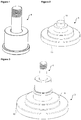
- the table (3) is in the form of a pyramid with a circular base (10) ( Figure 2 ).
- the motor casing (2) is in the form of a quadrangular prism and has a hole (9) at a point close to the ceiling thereof so as to align with the slit (7) on the mounting member (6) when the brake mechanism (5) is mounted thereon.
- the power cables which passes through the slit (7) on the mounting member (6) also passes through the hole (9), providing the electrical connection of the motor (1) in a quick and easy manner.
- the power cables are enabled to be taken out without being crushed and without being subject to other negative impacts, and the electrical connection of the motor (1) is provided.
- the motor (1) of the present invention is mounted as follows.
- the brake pull mechanism (4) is placed onto the table (3) so as to be on the step (11) on the table having the smallest diameter ( Figure 1 and Figure 3 ).
- the break mechanism (5) is fixed onto the table (3) so as to surround the brake pull mechanism (4) placed onto the table (3) ( Figure 4 ).
- the mounting member (6) is placed temporarily onto base (10) of the table (3) so as to surround the break mechanism (5) and the brake pull mechanism (4) from outside ( Figure 6 ).
- the power cables are passed through the slit (7) on the outer wall of the mounting member (6).
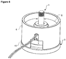
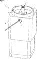
- the power cables which extend out from the slit (7) on the mounting member (6) are also passed through the hole (9) on the motor casing (2) and the motor casing (2) is fixedly attached such that the mounting member (6) is positioned between the motor casing (2) and the brake mechanism (5) ( Figure 7 ). Lastly, the mounting member (6) between the brake mechanism (5) and the motor casing (2) is removed and the mounting process is completed ( Figure 8 ).
- the motor (1) mounting method of the present invention suitable for the motor (1) explicated above comprises the steps of placing the brake pull mechanism (4) onto the table (3) onto the top step (11) on the table (3) having the smallest diameter, fixing the brake mechanism (5) onto the table (3) so as to surround the brake pull mechanism (4) placed onto the table (3), placing the mounting member (6) temporarily onto the base (10) of the table (3) so as to surround the brake mechanism (5) and the brake pull mechanism (4) from outside, passing the power cables through the slit (7) on the outer wall of the mounting member (6) and through the hole (9) on the motor casing (2), fixedly attaching the motor casing (2) such that the mounting member (6) is positioned between the motor casing (2) and the brake mechanism (5), and pulling and removing the mounting member (6) from between the brake mechanism (5) and the motor casing (2).
- the brake mechanism (5) is enabled to be mounted onto the motor (1) correctly and quickly, performing the mounting of the motor (1) in a quick and precise manner.
- the mounting member (6) By using the mounting member (6), the fixings member used while guiding the brake mechanism (5) and the brake pull mechanism (4) to each other are prevented from dislodging.
- the difficulties experienced during the guiding process are eliminated.
- the power cables are enabled to be passed through the motor casing (2) easily and quickly without being damaged.
Landscapes
- Engineering & Computer Science (AREA)
- General Engineering & Computer Science (AREA)
- Power Engineering (AREA)
- Mechanical Engineering (AREA)
- Connection Of Motors, Electrical Generators, Mechanical Devices, And The Like (AREA)
- Motor Or Generator Frames (AREA)
Abstract
Description
- The present invention relates to a special purpose servo motor with an electromagnetic brake and the mounting method of the motor.
- Special purpose servo motors are usually produced with electromagnetic brakes. In the state of the art several embodiments have been developed to facilitate and shorten the mounting process of the brake. During the mounting process, the bolts used as fixing members dislodge while the brake is being guided to the brake gear. Difficulty is experienced in the guiding of the brake to the brake gear. During the mounting of the brake to the motor, it is very difficult to hold together the manual brake mechanism parts which pass through the brake. Furthermore, while the brake is being guided and fitted to the brake gear, passing the power cables of the brake through the housing of the motor body creates difficulties and problems in the mounting of the motor.
- In the state of the art United States Patent No.
US5050711 , the fixing of the electromagnetic brake coupled with the motor shaft is disclosed. In this document, the electronic brake housing is fixed to a bracket. - The aim of the present invention is the realization of a special purpose servo motor with an electromagnetic brake and the mounting method of the motor.
- The motor realized in order to attain the aim of the present invention, explicated in the first claim and the respective claims thereof, comprises a brake pull mechanism, a table whereon the brake pull mechanism is disposed, a brake mechanism which is fixed onto the table so as to surround the brake pull mechanism placed onto the table, and a mounting member which is positioned on the table so as to surround the brake mechanism and the brake pull mechanism from outside, which enables the brake mechanism and the brake pull mechanism to be guided to each other and which comprises a slit allowing the passage of the power cables of the brake mechanism, wherein said components are grouped together.
- The mounting member is in the form of a hollow cylinder and has an upside down U-shaped slit on the side wall thereon. In the embodiment of the present invention, the slit is a quadrangle and a cut-out in the form of an upside down "U" provided on the quadrangle integrated to the mounting member.
- The table comprises a circular base and a plurality of, preferably three, circular steps on the base, each having a smaller diameter than that of the one below. The table is in the form of a pyramid with a circular base.
- The motor casing is in the form of a quadrangular prism and has a hole at a point close to the ceiling so as to align with the slit on the mounting member when the brake mechanism is mounted thereon. Thus, during the mounting process, the power cables which pass through the slit on the mounting member also pass through the hole, thus ensuring the electrical connection of the motor in a easy and quick manner. Thereby, during the mounting of the motor, the power cables are enabled to be taken out without being crushed and without being subject to other negative impacts, and the electrical connection of the motor is performed.
- The motor of the present invention is mounted as follows. The brake pull mechanism is placed onto the table so as to be on the step on the table with the smallest diameter. Then, the break mechanism is fixed onto the table so as to surround the brake pull mechanism placed onto the table. And then, the mounting member is placed temporarily onto base of the table so as to surround the break mechanism and the brake pull mechanism from outside. In this case, the cables are passed through the slit on the outer wall of the mounting member. The power cables which extend out from the slit on the mounting member are also passed through the hole on the motor casing, and the motor casing is fixedly attached such that the mounting member is positioned between the motor casing and the brake mechanism. Lastly, the mounting member between the brake mechanism and the motor casing is removed and the mounting process is completed.
- By means of the present invention, the brake mechanism is enabled to be mounted onto the motor correctly and quickly and mounting of the motor is enabled to be performed quickly and precisely. By using the mounting member, the fixing members used while the brake mechanism and the brake pull mechanism are guided to each other are prevented from dislodging. Thus, the difficulties experienced during the guiding process are eliminated. Furthermore, the power cables are enabled to be passed through the motor casing easily and quickly without being damaged.
- The motor realized in order to attain the aim of the present invention is illustrated in the attached figures, where:
-
Figure 1 - is the perspective view of a brake pull mechanism. -
Figure 2 - is the perspective view of a table. -
Figure 3 - is the perspective view of the brake pull mechanism placed onto the table. -
Figure 4 - is the perspective view of the brake mechanism fixed onto the table and the brake pull mechanism. -
Figure 5 - is the perspective view of a mounting member. -
Figure 6 - is the perspective view of the mounting member placed onto the brake mechanism. -
Figure 7 - is the perspective view of the motor casing wherein the brake mechanism and the mounting member are attached thereon. -
Figure 8 - is the perspective view of the motor the mounting of which is completed by removing the mounting member. - The elements illustrated in the figures are numbered as follows:
- 1.
- Motor
- 2.
- Motor casing
- 3.
- Table
- 4.
- Brake pull mechanism
- 5.
- Brake mechanism
- 6.
- Mounting member
- 7.
- Slit
- 8.
- Cut-out
- 9.
- Hole
- 10.
- Base
- 11.
- Step
- The motor (1) comprises a brake pull mechanism (4), a table (3) whereon the brake pull mechanism (4) is placed, a brake mechanism (5) which is fixed onto the table (3) so as to surround the brake pull mechanism (4) placed onto the table (3), a mounting member (6) which is positioned on the table (3) so as to surround the brake mechanism (5) and the brake pull mechanism (4) from outside, which enables the brake mechanism (5) and the brake pull mechanism (4) to be guided to each other and which comprises a slit (7) allowing the passage of the power cables of the brake mechanism (5).
- The mounting member (6) is in the form of a hollow cylinder and has an upside down U-shaped slit (7) on the side wall thereon. In the embodiment of the present invention, the mounting member (6) further comprises a quadrilateral cut-out (8) which adjoins the base of the mounting member (6) at the bottom edge thereof and the slit (7) at the upper edge thereof. The cut-out (8) enables the power cables of the mounting member (6) to be taken out easily without getting stuck (
Figure 5 ). - The table (3) comprises a circular base (10) and a plurality of, preferably three, circular steps (11) on the table (10), each having a smaller diameter than that of the one below. The table (3) is in the form of a pyramid with a circular base (10) (
Figure 2 ). - The motor casing (2) is in the form of a quadrangular prism and has a hole (9) at a point close to the ceiling thereof so as to align with the slit (7) on the mounting member (6) when the brake mechanism (5) is mounted thereon. Thus, during the mounting process, the power cables which passes through the slit (7) on the mounting member (6) also passes through the hole (9), providing the electrical connection of the motor (1) in a quick and easy manner. Thereby, during the mounting of the motor (1), the power cables are enabled to be taken out without being crushed and without being subject to other negative impacts, and the electrical connection of the motor (1) is provided.
- The motor (1) of the present invention is mounted as follows. The brake pull mechanism (4) is placed onto the table (3) so as to be on the step (11) on the table having the smallest diameter (
Figure 1 and Figure 3 ). Then, the break mechanism (5) is fixed onto the table (3) so as to surround the brake pull mechanism (4) placed onto the table (3) (Figure 4 ). Afterwards, the mounting member (6) is placed temporarily onto base (10) of the table (3) so as to surround the break mechanism (5) and the brake pull mechanism (4) from outside (Figure 6 ). In this case, the power cables are passed through the slit (7) on the outer wall of the mounting member (6). The power cables which extend out from the slit (7) on the mounting member (6) are also passed through the hole (9) on the motor casing (2) and the motor casing (2) is fixedly attached such that the mounting member (6) is positioned between the motor casing (2) and the brake mechanism (5) (Figure 7 ). Lastly, the mounting member (6) between the brake mechanism (5) and the motor casing (2) is removed and the mounting process is completed (Figure 8 ). - The motor (1) mounting method of the present invention suitable for the motor (1) explicated above comprises the steps of placing the brake pull mechanism (4) onto the table (3) onto the top step (11) on the table (3) having the smallest diameter, fixing the brake mechanism (5) onto the table (3) so as to surround the brake pull mechanism (4) placed onto the table (3), placing the mounting member (6) temporarily onto the base (10) of the table (3) so as to surround the brake mechanism (5) and the brake pull mechanism (4) from outside, passing the power cables through the slit (7) on the outer wall of the mounting member (6) and through the hole (9) on the motor casing (2), fixedly attaching the motor casing (2) such that the mounting member (6) is positioned between the motor casing (2) and the brake mechanism (5), and pulling and removing the mounting member (6) from between the brake mechanism (5) and the motor casing (2).
- By means of the present invention, the brake mechanism (5) is enabled to be mounted onto the motor (1) correctly and quickly, performing the mounting of the motor (1) in a quick and precise manner. By using the mounting member (6), the fixings member used while guiding the brake mechanism (5) and the brake pull mechanism (4) to each other are prevented from dislodging. Thus, the difficulties experienced during the guiding process are eliminated. Furthermore, the power cables are enabled to be passed through the motor casing (2) easily and quickly without being damaged.
Claims (8)
- A motor (1) comprising a brake pull mechanism (4), a table (3) whereon the brake pull mechanism (4) is placed, a brake mechanism (5) which is fixed onto the table (3) so as to surround the brake pull mechanism (4) placed onto the table (3), characterized by a mounting member (6) which is positioned on the table (3) so as to surround the brake mechanism (5) and the brake pull mechanism (4) from outside, which enables the brake mechanism (5) and the brake pull mechanism (4) to be guided to each other and which comprises a slit (7) allowing the passage of the power cables of the brake mechanism (5).
- A motor (1) as in Claim 1, characterized by the mounting member (6) which is in the form of a hollow cylinder and has an upside down U-shaped slit (7) on the side wall thereon.
- A motor (1) as in Claim 1 and 2, characterized by the mounting member (6) comprising a quadrilateral cut-out (8) which adjoins the base of the mounting member (6) at the bottom edge thereof and the slit (7) at the upper edge thereof.
- A motor (1) as in Claim 1, characterized by the table (3) comprising a circular base (10) and a plurality of circular steps (11) on the table (10), each having a smaller diameter than that of the one below.
- A motor (1) as in Claim 4, characterized by the table (3) comprising three circular steps (3).
- A motor (1) as in Claim 1, 4 and 5, characterized by the table (3) which is in the form of a pyramid having a circular base.
- A motor (1) as in Claim 1, 2 and 3, characterized by the motor casing (2) which is in the form of a quadrangular prism and has a hole (9) at a point close to the ceiling thereof so as to align with the slit (7) on the mounting member (6) when the brake mechanism (5) is mounted thereon.
- A motor (1) mounting method characterized by the steps of placing the brake pull mechanism (4) onto the table (3) onto the top step (11) on the table (3) having the smallest diameter, fixing the brake mechanism (5) onto the table (3) so as to surround the brake pull mechanism (4) placed onto the table (3), placing the mounting member (6) temporarily onto the base (10) of the table (3) so as to surround the brake mechanism (5) and the brake pull mechanism (4) from outside, passing the power cables through the slit (7) on the outer wall of the mounting member (6) and through the hole (9) on the motor casing (2), fixedly attaching the motor casing (2) such that the mounting member (6) is positioned between the motor casing (2) and the brake mechanism (5), and pulling and removing the mounting member (6) from between the brake mechanism (5) and the motor casing (2).
Applications Claiming Priority (1)
| Application Number | Priority Date | Filing Date | Title |
|---|---|---|---|
| TR201920227 | 2019-12-13 |
Publications (3)
| Publication Number | Publication Date |
|---|---|
| EP3835611A2 true EP3835611A2 (en) | 2021-06-16 |
| EP3835611A3 EP3835611A3 (en) | 2021-08-04 |
| EP3835611B1 EP3835611B1 (en) | 2024-01-03 |
Family
ID=73646082
Family Applications (1)
| Application Number | Title | Priority Date | Filing Date |
|---|---|---|---|
| EP20210273.7A Active EP3835611B1 (en) | 2019-12-13 | 2020-11-27 | A motor and a motor mounting method |
Country Status (1)
| Country | Link |
|---|---|
| EP (1) | EP3835611B1 (en) |
Citations (1)
| Publication number | Priority date | Publication date | Assignee | Title |
|---|---|---|---|---|
| US5050711A (en) | 1989-03-16 | 1991-09-24 | Mitsubishi Denki Kabushiki Kaisha | Electromagnetic brake apparatus |
Family Cites Families (1)
| Publication number | Priority date | Publication date | Assignee | Title |
|---|---|---|---|---|
| CN102102482B (en) * | 2009-12-18 | 2015-07-01 | 德昌电机(深圳)有限公司 | Roller shutter driving device |
-
2020
- 2020-11-27 EP EP20210273.7A patent/EP3835611B1/en active Active
Patent Citations (1)
| Publication number | Priority date | Publication date | Assignee | Title |
|---|---|---|---|---|
| US5050711A (en) | 1989-03-16 | 1991-09-24 | Mitsubishi Denki Kabushiki Kaisha | Electromagnetic brake apparatus |
Also Published As
| Publication number | Publication date |
|---|---|
| EP3835611B1 (en) | 2024-01-03 |
| EP3835611A3 (en) | 2021-08-04 |
Similar Documents
| Publication | Publication Date | Title |
|---|---|---|
| KR101484298B1 (en) | Apparatus for installation stator with motor housing | |
| EP1903848B1 (en) | Modular frequency converter comprising an installation cabinet | |
| CN111048443B (en) | Mold ejection device | |
| KR20150118190A (en) | Method and apparatus for removal and replacement of a wound stator core | |
| CN106956937A (en) | A kind of band automatically feeds the material box mechanism of function | |
| EP3835611B1 (en) | A motor and a motor mounting method | |
| KR101773438B1 (en) | System for installation stator with motor housing | |
| CN109639016A (en) | A kind of permanent magnet motor stator segment separator structure | |
| JP4607355B2 (en) | Generator / motor stator assembly equipment | |
| EP4442993A1 (en) | Method for installing a wind turbine tower | |
| CN108768099B (en) | Stripping tool | |
| EP3038239B1 (en) | Methods of assembling an electrical machine | |
| JPH11199150A (en) | Disassembly method of electromagnetic brake device for elevator | |
| CN214222432U (en) | Metal box convenient to installation | |
| CN103787162A (en) | Brake separation device of elevator | |
| CN115740199B (en) | One-step stamping forming equipment for automobile parts and use method thereof | |
| CN208479412U (en) | stripping tool | |
| EP4068595A1 (en) | Motor splitting or assembling apparatus, motor splitting method, and motor assembling method | |
| JP2022148413A (en) | Pulley detachment jig, shaft pull out device and shaft insertion device | |
| CN213002244U (en) | Tooling for riveting and assembling of electric vehicle gear parts | |
| JP2017131100A (en) | Conductor bar stripping tool and method | |
| CN104094506B (en) | Armature assembly for generator | |
| KR101008038B1 (en) | Scrap Coil Separator in Sleeve | |
| CN105459020A (en) | Magnet mounting tool and magnet mounting method | |
| CN219372223U (en) | Assembling and disassembling device suitable for motor rotor |
Legal Events
| Date | Code | Title | Description |
|---|---|---|---|
| PUAI | Public reference made under article 153(3) epc to a published international application that has entered the european phase |
Free format text: ORIGINAL CODE: 0009012 |
|
| STAA | Information on the status of an ep patent application or granted ep patent |
Free format text: STATUS: REQUEST FOR EXAMINATION WAS MADE |
|
| 17P | Request for examination filed |
Effective date: 20201127 |
|
| AK | Designated contracting states |
Kind code of ref document: A2 Designated state(s): AL AT BE BG CH CY CZ DE DK EE ES FI FR GB GR HR HU IE IS IT LI LT LU LV MC MK MT NL NO PL PT RO RS SE SI SK SM TR |
|
| PUAL | Search report despatched |
Free format text: ORIGINAL CODE: 0009013 |
|
| AK | Designated contracting states |
Kind code of ref document: A3 Designated state(s): AL AT BE BG CH CY CZ DE DK EE ES FI FR GB GR HR HU IE IS IT LI LT LU LV MC MK MT NL NO PL PT RO RS SE SI SK SM TR |
|
| RIC1 | Information provided on ipc code assigned before grant |
Ipc: F16D 55/00 20060101AFI20210628BHEP Ipc: D05B 69/12 20060101ALI20210628BHEP Ipc: H02K 7/102 20060101ALI20210628BHEP Ipc: H02K 7/11 20060101ALI20210628BHEP Ipc: F16D 65/18 20060101ALI20210628BHEP |
|
| GRAP | Despatch of communication of intention to grant a patent |
Free format text: ORIGINAL CODE: EPIDOSNIGR1 |
|
| STAA | Information on the status of an ep patent application or granted ep patent |
Free format text: STATUS: GRANT OF PATENT IS INTENDED |
|
| RIC1 | Information provided on ipc code assigned before grant |
Ipc: F16D 65/18 20060101ALI20230817BHEP Ipc: H02K 7/11 20060101ALI20230817BHEP Ipc: H02K 7/102 20060101ALI20230817BHEP Ipc: D05B 69/12 20060101ALI20230817BHEP Ipc: F16D 55/00 20060101AFI20230817BHEP |
|
| INTG | Intention to grant announced |
Effective date: 20230908 |
|
| GRAS | Grant fee paid |
Free format text: ORIGINAL CODE: EPIDOSNIGR3 |
|
| GRAA | (expected) grant |
Free format text: ORIGINAL CODE: 0009210 |
|
| STAA | Information on the status of an ep patent application or granted ep patent |
Free format text: STATUS: THE PATENT HAS BEEN GRANTED |
|
| AK | Designated contracting states |
Kind code of ref document: B1 Designated state(s): AL AT BE BG CH CY CZ DE DK EE ES FI FR GB GR HR HU IE IS IT LI LT LU LV MC MK MT NL NO PL PT RO RS SE SI SK SM TR |
|
| REG | Reference to a national code |
Ref country code: GB Ref legal event code: FG4D |
|
| REG | Reference to a national code |
Ref country code: DE Ref legal event code: R096 Ref document number: 602020023767 Country of ref document: DE |
|
| REG | Reference to a national code |
Ref country code: CH Ref legal event code: EP |
|
| REG | Reference to a national code |
Ref country code: IE Ref legal event code: FG4D |
|
| REG | Reference to a national code |
Ref country code: LT Ref legal event code: MG9D |
|
| PG25 | Lapsed in a contracting state [announced via postgrant information from national office to epo] |
Ref country code: ES Free format text: LAPSE BECAUSE OF FAILURE TO SUBMIT A TRANSLATION OF THE DESCRIPTION OR TO PAY THE FEE WITHIN THE PRESCRIBED TIME-LIMIT Effective date: 20240103 |
|
| PG25 | Lapsed in a contracting state [announced via postgrant information from national office to epo] |
Ref country code: ES Free format text: LAPSE BECAUSE OF FAILURE TO SUBMIT A TRANSLATION OF THE DESCRIPTION OR TO PAY THE FEE WITHIN THE PRESCRIBED TIME-LIMIT Effective date: 20240103 |
|
| REG | Reference to a national code |
Ref country code: NL Ref legal event code: MP Effective date: 20240103 |
|
| REG | Reference to a national code |
Ref country code: AT Ref legal event code: MK05 Ref document number: 1647084 Country of ref document: AT Kind code of ref document: T Effective date: 20240103 |
|
| PG25 | Lapsed in a contracting state [announced via postgrant information from national office to epo] |
Ref country code: NL Free format text: LAPSE BECAUSE OF FAILURE TO SUBMIT A TRANSLATION OF THE DESCRIPTION OR TO PAY THE FEE WITHIN THE PRESCRIBED TIME-LIMIT Effective date: 20240103 |
|
| PG25 | Lapsed in a contracting state [announced via postgrant information from national office to epo] |
Ref country code: NL Free format text: LAPSE BECAUSE OF FAILURE TO SUBMIT A TRANSLATION OF THE DESCRIPTION OR TO PAY THE FEE WITHIN THE PRESCRIBED TIME-LIMIT Effective date: 20240103 |
|
| PG25 | Lapsed in a contracting state [announced via postgrant information from national office to epo] |
Ref country code: IS Free format text: LAPSE BECAUSE OF FAILURE TO SUBMIT A TRANSLATION OF THE DESCRIPTION OR TO PAY THE FEE WITHIN THE PRESCRIBED TIME-LIMIT Effective date: 20240503 |
|
| PG25 | Lapsed in a contracting state [announced via postgrant information from national office to epo] |
Ref country code: LT Free format text: LAPSE BECAUSE OF FAILURE TO SUBMIT A TRANSLATION OF THE DESCRIPTION OR TO PAY THE FEE WITHIN THE PRESCRIBED TIME-LIMIT Effective date: 20240103 |
|
| PG25 | Lapsed in a contracting state [announced via postgrant information from national office to epo] |
Ref country code: GR Free format text: LAPSE BECAUSE OF FAILURE TO SUBMIT A TRANSLATION OF THE DESCRIPTION OR TO PAY THE FEE WITHIN THE PRESCRIBED TIME-LIMIT Effective date: 20240404 |
|
| PG25 | Lapsed in a contracting state [announced via postgrant information from national office to epo] |
Ref country code: RS Free format text: LAPSE BECAUSE OF FAILURE TO SUBMIT A TRANSLATION OF THE DESCRIPTION OR TO PAY THE FEE WITHIN THE PRESCRIBED TIME-LIMIT Effective date: 20240403 Ref country code: HR Free format text: LAPSE BECAUSE OF FAILURE TO SUBMIT A TRANSLATION OF THE DESCRIPTION OR TO PAY THE FEE WITHIN THE PRESCRIBED TIME-LIMIT Effective date: 20240103 |
|
| PG25 | Lapsed in a contracting state [announced via postgrant information from national office to epo] |
Ref country code: AT Free format text: LAPSE BECAUSE OF FAILURE TO SUBMIT A TRANSLATION OF THE DESCRIPTION OR TO PAY THE FEE WITHIN THE PRESCRIBED TIME-LIMIT Effective date: 20240103 Ref country code: CZ Free format text: LAPSE BECAUSE OF FAILURE TO SUBMIT A TRANSLATION OF THE DESCRIPTION OR TO PAY THE FEE WITHIN THE PRESCRIBED TIME-LIMIT Effective date: 20240103 |
|
| PG25 | Lapsed in a contracting state [announced via postgrant information from national office to epo] |
Ref country code: RS Free format text: LAPSE BECAUSE OF FAILURE TO SUBMIT A TRANSLATION OF THE DESCRIPTION OR TO PAY THE FEE WITHIN THE PRESCRIBED TIME-LIMIT Effective date: 20240403 Ref country code: NO Free format text: LAPSE BECAUSE OF FAILURE TO SUBMIT A TRANSLATION OF THE DESCRIPTION OR TO PAY THE FEE WITHIN THE PRESCRIBED TIME-LIMIT Effective date: 20240403 Ref country code: LT Free format text: LAPSE BECAUSE OF FAILURE TO SUBMIT A TRANSLATION OF THE DESCRIPTION OR TO PAY THE FEE WITHIN THE PRESCRIBED TIME-LIMIT Effective date: 20240103 Ref country code: IS Free format text: LAPSE BECAUSE OF FAILURE TO SUBMIT A TRANSLATION OF THE DESCRIPTION OR TO PAY THE FEE WITHIN THE PRESCRIBED TIME-LIMIT Effective date: 20240503 Ref country code: HR Free format text: LAPSE BECAUSE OF FAILURE TO SUBMIT A TRANSLATION OF THE DESCRIPTION OR TO PAY THE FEE WITHIN THE PRESCRIBED TIME-LIMIT Effective date: 20240103 Ref country code: GR Free format text: LAPSE BECAUSE OF FAILURE TO SUBMIT A TRANSLATION OF THE DESCRIPTION OR TO PAY THE FEE WITHIN THE PRESCRIBED TIME-LIMIT Effective date: 20240404 Ref country code: CZ Free format text: LAPSE BECAUSE OF FAILURE TO SUBMIT A TRANSLATION OF THE DESCRIPTION OR TO PAY THE FEE WITHIN THE PRESCRIBED TIME-LIMIT Effective date: 20240103 Ref country code: BG Free format text: LAPSE BECAUSE OF FAILURE TO SUBMIT A TRANSLATION OF THE DESCRIPTION OR TO PAY THE FEE WITHIN THE PRESCRIBED TIME-LIMIT Effective date: 20240103 Ref country code: AT Free format text: LAPSE BECAUSE OF FAILURE TO SUBMIT A TRANSLATION OF THE DESCRIPTION OR TO PAY THE FEE WITHIN THE PRESCRIBED TIME-LIMIT Effective date: 20240103 |
|
| PG25 | Lapsed in a contracting state [announced via postgrant information from national office to epo] |
Ref country code: PL Free format text: LAPSE BECAUSE OF FAILURE TO SUBMIT A TRANSLATION OF THE DESCRIPTION OR TO PAY THE FEE WITHIN THE PRESCRIBED TIME-LIMIT Effective date: 20240103 Ref country code: PT Free format text: LAPSE BECAUSE OF FAILURE TO SUBMIT A TRANSLATION OF THE DESCRIPTION OR TO PAY THE FEE WITHIN THE PRESCRIBED TIME-LIMIT Effective date: 20240503 |
|
| PG25 | Lapsed in a contracting state [announced via postgrant information from national office to epo] |
Ref country code: SE Free format text: LAPSE BECAUSE OF FAILURE TO SUBMIT A TRANSLATION OF THE DESCRIPTION OR TO PAY THE FEE WITHIN THE PRESCRIBED TIME-LIMIT Effective date: 20240103 Ref country code: PT Free format text: LAPSE BECAUSE OF FAILURE TO SUBMIT A TRANSLATION OF THE DESCRIPTION OR TO PAY THE FEE WITHIN THE PRESCRIBED TIME-LIMIT Effective date: 20240503 Ref country code: PL Free format text: LAPSE BECAUSE OF FAILURE TO SUBMIT A TRANSLATION OF THE DESCRIPTION OR TO PAY THE FEE WITHIN THE PRESCRIBED TIME-LIMIT Effective date: 20240103 Ref country code: LV Free format text: LAPSE BECAUSE OF FAILURE TO SUBMIT A TRANSLATION OF THE DESCRIPTION OR TO PAY THE FEE WITHIN THE PRESCRIBED TIME-LIMIT Effective date: 20240103 |
|
| REG | Reference to a national code |
Ref country code: DE Ref legal event code: R097 Ref document number: 602020023767 Country of ref document: DE |
|
| PG25 | Lapsed in a contracting state [announced via postgrant information from national office to epo] |
Ref country code: DK Free format text: LAPSE BECAUSE OF FAILURE TO SUBMIT A TRANSLATION OF THE DESCRIPTION OR TO PAY THE FEE WITHIN THE PRESCRIBED TIME-LIMIT Effective date: 20240103 |
|
| PG25 | Lapsed in a contracting state [announced via postgrant information from national office to epo] |
Ref country code: SM Free format text: LAPSE BECAUSE OF FAILURE TO SUBMIT A TRANSLATION OF THE DESCRIPTION OR TO PAY THE FEE WITHIN THE PRESCRIBED TIME-LIMIT Effective date: 20240103 |
|
| PG25 | Lapsed in a contracting state [announced via postgrant information from national office to epo] |
Ref country code: EE Free format text: LAPSE BECAUSE OF FAILURE TO SUBMIT A TRANSLATION OF THE DESCRIPTION OR TO PAY THE FEE WITHIN THE PRESCRIBED TIME-LIMIT Effective date: 20240103 |
|
| PG25 | Lapsed in a contracting state [announced via postgrant information from national office to epo] |
Ref country code: SK Free format text: LAPSE BECAUSE OF FAILURE TO SUBMIT A TRANSLATION OF THE DESCRIPTION OR TO PAY THE FEE WITHIN THE PRESCRIBED TIME-LIMIT Effective date: 20240103 |
|
| PG25 | Lapsed in a contracting state [announced via postgrant information from national office to epo] |
Ref country code: SM Free format text: LAPSE BECAUSE OF FAILURE TO SUBMIT A TRANSLATION OF THE DESCRIPTION OR TO PAY THE FEE WITHIN THE PRESCRIBED TIME-LIMIT Effective date: 20240103 Ref country code: SK Free format text: LAPSE BECAUSE OF FAILURE TO SUBMIT A TRANSLATION OF THE DESCRIPTION OR TO PAY THE FEE WITHIN THE PRESCRIBED TIME-LIMIT Effective date: 20240103 Ref country code: RO Free format text: LAPSE BECAUSE OF FAILURE TO SUBMIT A TRANSLATION OF THE DESCRIPTION OR TO PAY THE FEE WITHIN THE PRESCRIBED TIME-LIMIT Effective date: 20240103 Ref country code: EE Free format text: LAPSE BECAUSE OF FAILURE TO SUBMIT A TRANSLATION OF THE DESCRIPTION OR TO PAY THE FEE WITHIN THE PRESCRIBED TIME-LIMIT Effective date: 20240103 Ref country code: DK Free format text: LAPSE BECAUSE OF FAILURE TO SUBMIT A TRANSLATION OF THE DESCRIPTION OR TO PAY THE FEE WITHIN THE PRESCRIBED TIME-LIMIT Effective date: 20240103 |
|
| PLBE | No opposition filed within time limit |
Free format text: ORIGINAL CODE: 0009261 |
|
| STAA | Information on the status of an ep patent application or granted ep patent |
Free format text: STATUS: NO OPPOSITION FILED WITHIN TIME LIMIT |
|
| PG25 | Lapsed in a contracting state [announced via postgrant information from national office to epo] |
Ref country code: IT Free format text: LAPSE BECAUSE OF FAILURE TO SUBMIT A TRANSLATION OF THE DESCRIPTION OR TO PAY THE FEE WITHIN THE PRESCRIBED TIME-LIMIT Effective date: 20240103 |
|
| 26N | No opposition filed |
Effective date: 20241007 |
|
| PG25 | Lapsed in a contracting state [announced via postgrant information from national office to epo] |
Ref country code: IT Free format text: LAPSE BECAUSE OF FAILURE TO SUBMIT A TRANSLATION OF THE DESCRIPTION OR TO PAY THE FEE WITHIN THE PRESCRIBED TIME-LIMIT Effective date: 20240103 |
|
| PG25 | Lapsed in a contracting state [announced via postgrant information from national office to epo] |
Ref country code: SI Free format text: LAPSE BECAUSE OF FAILURE TO SUBMIT A TRANSLATION OF THE DESCRIPTION OR TO PAY THE FEE WITHIN THE PRESCRIBED TIME-LIMIT Effective date: 20240103 |
|
| REG | Reference to a national code |
Ref country code: DE Ref legal event code: R119 Ref document number: 602020023767 Country of ref document: DE |
|
| REG | Reference to a national code |
Ref country code: CH Ref legal event code: PL |
|
| PG25 | Lapsed in a contracting state [announced via postgrant information from national office to epo] |
Ref country code: MC Free format text: LAPSE BECAUSE OF FAILURE TO SUBMIT A TRANSLATION OF THE DESCRIPTION OR TO PAY THE FEE WITHIN THE PRESCRIBED TIME-LIMIT Effective date: 20240103 |
|
| PG25 | Lapsed in a contracting state [announced via postgrant information from national office to epo] |
Ref country code: LU Free format text: LAPSE BECAUSE OF NON-PAYMENT OF DUE FEES Effective date: 20241127 |
|
| REG | Reference to a national code |
Ref country code: CH Ref legal event code: PL |
|
| GBPC | Gb: european patent ceased through non-payment of renewal fee |
Effective date: 20241127 |
|
| PG25 | Lapsed in a contracting state [announced via postgrant information from national office to epo] |
Ref country code: CH Free format text: LAPSE BECAUSE OF NON-PAYMENT OF DUE FEES Effective date: 20241130 |
|
| REG | Reference to a national code |
Ref country code: BE Ref legal event code: MM Effective date: 20241130 |
|
| PG25 | Lapsed in a contracting state [announced via postgrant information from national office to epo] |
Ref country code: FI Free format text: LAPSE BECAUSE OF FAILURE TO SUBMIT A TRANSLATION OF THE DESCRIPTION OR TO PAY THE FEE WITHIN THE PRESCRIBED TIME-LIMIT Effective date: 20240103 |
|
| PG25 | Lapsed in a contracting state [announced via postgrant information from national office to epo] |
Ref country code: DE Free format text: LAPSE BECAUSE OF NON-PAYMENT OF DUE FEES Effective date: 20250603 |
|
| PG25 | Lapsed in a contracting state [announced via postgrant information from national office to epo] |
Ref country code: GB Free format text: LAPSE BECAUSE OF NON-PAYMENT OF DUE FEES Effective date: 20241127 Ref country code: BE Free format text: LAPSE BECAUSE OF NON-PAYMENT OF DUE FEES Effective date: 20241130 |
|
| PG25 | Lapsed in a contracting state [announced via postgrant information from national office to epo] |
Ref country code: FR Free format text: LAPSE BECAUSE OF NON-PAYMENT OF DUE FEES Effective date: 20241130 |
|
| PG25 | Lapsed in a contracting state [announced via postgrant information from national office to epo] |
Ref country code: IE Free format text: LAPSE BECAUSE OF NON-PAYMENT OF DUE FEES Effective date: 20241127 |
|
| PGFP | Annual fee paid to national office [announced via postgrant information from national office to epo] |
Ref country code: TR Payment date: 20251111 Year of fee payment: 6 |
|
| PG25 | Lapsed in a contracting state [announced via postgrant information from national office to epo] |
Ref country code: HU Free format text: LAPSE BECAUSE OF FAILURE TO SUBMIT A TRANSLATION OF THE DESCRIPTION OR TO PAY THE FEE WITHIN THE PRESCRIBED TIME-LIMIT; INVALID AB INITIO Effective date: 20201127 |
|
| PG25 | Lapsed in a contracting state [announced via postgrant information from national office to epo] |
Ref country code: CY Free format text: LAPSE BECAUSE OF FAILURE TO SUBMIT A TRANSLATION OF THE DESCRIPTION OR TO PAY THE FEE WITHIN THE PRESCRIBED TIME-LIMIT; INVALID AB INITIO Effective date: 20201127 |