EP3835598A1 - Construction machine - Google Patents
Construction machine Download PDFInfo
- Publication number
- EP3835598A1 EP3835598A1 EP19911321.8A EP19911321A EP3835598A1 EP 3835598 A1 EP3835598 A1 EP 3835598A1 EP 19911321 A EP19911321 A EP 19911321A EP 3835598 A1 EP3835598 A1 EP 3835598A1
- Authority
- EP
- European Patent Office
- Prior art keywords
- closed circuit
- swing
- flushing valve
- tank
- pump
- Prior art date
- Legal status (The legal status is an assumption and is not a legal conclusion. Google has not performed a legal analysis and makes no representation as to the accuracy of the status listed.)
- Granted
Links
Images


Classifications
-
- F—MECHANICAL ENGINEERING; LIGHTING; HEATING; WEAPONS; BLASTING
- F15—FLUID-PRESSURE ACTUATORS; HYDRAULICS OR PNEUMATICS IN GENERAL
- F15B—SYSTEMS ACTING BY MEANS OF FLUIDS IN GENERAL; FLUID-PRESSURE ACTUATORS, e.g. SERVOMOTORS; DETAILS OF FLUID-PRESSURE SYSTEMS, NOT OTHERWISE PROVIDED FOR
- F15B7/00—Systems in which the movement produced is definitely related to the output of a volumetric pump; Telemotors
- F15B7/005—With rotary or crank input
- F15B7/006—Rotary pump input
-
- E—FIXED CONSTRUCTIONS
- E02—HYDRAULIC ENGINEERING; FOUNDATIONS; SOIL SHIFTING
- E02F—DREDGING; SOIL-SHIFTING
- E02F9/00—Component parts of dredgers or soil-shifting machines, not restricted to one of the kinds covered by groups E02F3/00 - E02F7/00
- E02F9/08—Superstructures; Supports for superstructures
- E02F9/10—Supports for movable superstructures mounted on travelling or walking gears or on other superstructures
- E02F9/12—Slewing or traversing gears
- E02F9/121—Turntables, i.e. structure rotatable about 360°
- E02F9/123—Drives or control devices specially adapted therefor
-
- E—FIXED CONSTRUCTIONS
- E02—HYDRAULIC ENGINEERING; FOUNDATIONS; SOIL SHIFTING
- E02F—DREDGING; SOIL-SHIFTING
- E02F3/00—Dredgers; Soil-shifting machines
- E02F3/04—Dredgers; Soil-shifting machines mechanically-driven
- E02F3/28—Dredgers; Soil-shifting machines mechanically-driven with digging tools mounted on a dipper- or bucket-arm, i.e. there is either one arm or a pair of arms, e.g. dippers, buckets
- E02F3/30—Dredgers; Soil-shifting machines mechanically-driven with digging tools mounted on a dipper- or bucket-arm, i.e. there is either one arm or a pair of arms, e.g. dippers, buckets with a dipper-arm pivoted on a cantilever beam, i.e. boom
- E02F3/32—Dredgers; Soil-shifting machines mechanically-driven with digging tools mounted on a dipper- or bucket-arm, i.e. there is either one arm or a pair of arms, e.g. dippers, buckets with a dipper-arm pivoted on a cantilever beam, i.e. boom working downwardly and towards the machine, e.g. with backhoes
-
- E—FIXED CONSTRUCTIONS
- E02—HYDRAULIC ENGINEERING; FOUNDATIONS; SOIL SHIFTING
- E02F—DREDGING; SOIL-SHIFTING
- E02F9/00—Component parts of dredgers or soil-shifting machines, not restricted to one of the kinds covered by groups E02F3/00 - E02F7/00
- E02F9/20—Drives; Control devices
- E02F9/22—Hydraulic or pneumatic drives
- E02F9/2221—Control of flow rate; Load sensing arrangements
- E02F9/2225—Control of flow rate; Load sensing arrangements using pressure-compensating valves
- E02F9/2228—Control of flow rate; Load sensing arrangements using pressure-compensating valves including an electronic controller
-
- E—FIXED CONSTRUCTIONS
- E02—HYDRAULIC ENGINEERING; FOUNDATIONS; SOIL SHIFTING
- E02F—DREDGING; SOIL-SHIFTING
- E02F9/00—Component parts of dredgers or soil-shifting machines, not restricted to one of the kinds covered by groups E02F3/00 - E02F7/00
- E02F9/20—Drives; Control devices
- E02F9/22—Hydraulic or pneumatic drives
- E02F9/2221—Control of flow rate; Load sensing arrangements
- E02F9/2232—Control of flow rate; Load sensing arrangements using one or more variable displacement pumps
- E02F9/2235—Control of flow rate; Load sensing arrangements using one or more variable displacement pumps including an electronic controller
-
- E—FIXED CONSTRUCTIONS
- E02—HYDRAULIC ENGINEERING; FOUNDATIONS; SOIL SHIFTING
- E02F—DREDGING; SOIL-SHIFTING
- E02F9/00—Component parts of dredgers or soil-shifting machines, not restricted to one of the kinds covered by groups E02F3/00 - E02F7/00
- E02F9/20—Drives; Control devices
- E02F9/22—Hydraulic or pneumatic drives
- E02F9/2278—Hydraulic circuits
- E02F9/2285—Pilot-operated systems
-
- E—FIXED CONSTRUCTIONS
- E02—HYDRAULIC ENGINEERING; FOUNDATIONS; SOIL SHIFTING
- E02F—DREDGING; SOIL-SHIFTING
- E02F9/00—Component parts of dredgers or soil-shifting machines, not restricted to one of the kinds covered by groups E02F3/00 - E02F7/00
- E02F9/20—Drives; Control devices
- E02F9/22—Hydraulic or pneumatic drives
- E02F9/2278—Hydraulic circuits
- E02F9/2289—Closed circuit
-
- E—FIXED CONSTRUCTIONS
- E02—HYDRAULIC ENGINEERING; FOUNDATIONS; SOIL SHIFTING
- E02F—DREDGING; SOIL-SHIFTING
- E02F9/00—Component parts of dredgers or soil-shifting machines, not restricted to one of the kinds covered by groups E02F3/00 - E02F7/00
- E02F9/20—Drives; Control devices
- E02F9/22—Hydraulic or pneumatic drives
- E02F9/2278—Hydraulic circuits
- E02F9/2292—Systems with two or more pumps
-
- E—FIXED CONSTRUCTIONS
- E02—HYDRAULIC ENGINEERING; FOUNDATIONS; SOIL SHIFTING
- E02F—DREDGING; SOIL-SHIFTING
- E02F9/00—Component parts of dredgers or soil-shifting machines, not restricted to one of the kinds covered by groups E02F3/00 - E02F7/00
- E02F9/20—Drives; Control devices
- E02F9/22—Hydraulic or pneumatic drives
- E02F9/2278—Hydraulic circuits
- E02F9/2296—Systems with a variable displacement pump
-
- F—MECHANICAL ENGINEERING; LIGHTING; HEATING; WEAPONS; BLASTING
- F15—FLUID-PRESSURE ACTUATORS; HYDRAULICS OR PNEUMATICS IN GENERAL
- F15B—SYSTEMS ACTING BY MEANS OF FLUIDS IN GENERAL; FLUID-PRESSURE ACTUATORS, e.g. SERVOMOTORS; DETAILS OF FLUID-PRESSURE SYSTEMS, NOT OTHERWISE PROVIDED FOR
- F15B11/00—Servomotor systems without provision for follow-up action ; Circuits therefor
- F15B11/02—Systems essentially incorporating special features for controlling the speed or the actuating force of an output member
- F15B11/04—Systems essentially incorporating special features for controlling the speed or the actuating force of an output member for controlling the speed
- F15B11/0406—Systems essentially incorporating special features for controlling the speed or the actuating force of an output member for controlling the speed during starting or stopping
-
- F—MECHANICAL ENGINEERING; LIGHTING; HEATING; WEAPONS; BLASTING
- F15—FLUID-PRESSURE ACTUATORS; HYDRAULICS OR PNEUMATICS IN GENERAL
- F15B—SYSTEMS ACTING BY MEANS OF FLUIDS IN GENERAL; FLUID-PRESSURE ACTUATORS, e.g. SERVOMOTORS; DETAILS OF FLUID-PRESSURE SYSTEMS, NOT OTHERWISE PROVIDED FOR
- F15B11/00—Servomotor systems without provision for follow-up action ; Circuits therefor
- F15B11/16—Servomotor systems without provision for follow-up action ; Circuits therefor with two or more servomotors
- F15B11/17—Servomotor systems without provision for follow-up action ; Circuits therefor with two or more servomotors using two or more pumps
-
- F—MECHANICAL ENGINEERING; LIGHTING; HEATING; WEAPONS; BLASTING
- F15—FLUID-PRESSURE ACTUATORS; HYDRAULICS OR PNEUMATICS IN GENERAL
- F15B—SYSTEMS ACTING BY MEANS OF FLUIDS IN GENERAL; FLUID-PRESSURE ACTUATORS, e.g. SERVOMOTORS; DETAILS OF FLUID-PRESSURE SYSTEMS, NOT OTHERWISE PROVIDED FOR
- F15B13/00—Details of servomotor systems ; Valves for servomotor systems
- F15B13/02—Fluid distribution or supply devices characterised by their adaptation to the control of servomotors
- F15B13/04—Fluid distribution or supply devices characterised by their adaptation to the control of servomotors for use with a single servomotor
- F15B13/042—Fluid distribution or supply devices characterised by their adaptation to the control of servomotors for use with a single servomotor operated by fluid pressure
-
- F—MECHANICAL ENGINEERING; LIGHTING; HEATING; WEAPONS; BLASTING
- F15—FLUID-PRESSURE ACTUATORS; HYDRAULICS OR PNEUMATICS IN GENERAL
- F15B—SYSTEMS ACTING BY MEANS OF FLUIDS IN GENERAL; FLUID-PRESSURE ACTUATORS, e.g. SERVOMOTORS; DETAILS OF FLUID-PRESSURE SYSTEMS, NOT OTHERWISE PROVIDED FOR
- F15B7/00—Systems in which the movement produced is definitely related to the output of a volumetric pump; Telemotors
- F15B7/008—Systems in which the movement produced is definitely related to the output of a volumetric pump; Telemotors with rotary output
-
- F—MECHANICAL ENGINEERING; LIGHTING; HEATING; WEAPONS; BLASTING
- F15—FLUID-PRESSURE ACTUATORS; HYDRAULICS OR PNEUMATICS IN GENERAL
- F15B—SYSTEMS ACTING BY MEANS OF FLUIDS IN GENERAL; FLUID-PRESSURE ACTUATORS, e.g. SERVOMOTORS; DETAILS OF FLUID-PRESSURE SYSTEMS, NOT OTHERWISE PROVIDED FOR
- F15B2211/00—Circuits for servomotor systems
- F15B2211/20—Fluid pressure source, e.g. accumulator or variable axial piston pump
- F15B2211/205—Systems with pumps
- F15B2211/20507—Type of prime mover
- F15B2211/20523—Internal combustion engine
-
- F—MECHANICAL ENGINEERING; LIGHTING; HEATING; WEAPONS; BLASTING
- F15—FLUID-PRESSURE ACTUATORS; HYDRAULICS OR PNEUMATICS IN GENERAL
- F15B—SYSTEMS ACTING BY MEANS OF FLUIDS IN GENERAL; FLUID-PRESSURE ACTUATORS, e.g. SERVOMOTORS; DETAILS OF FLUID-PRESSURE SYSTEMS, NOT OTHERWISE PROVIDED FOR
- F15B2211/00—Circuits for servomotor systems
- F15B2211/20—Fluid pressure source, e.g. accumulator or variable axial piston pump
- F15B2211/205—Systems with pumps
- F15B2211/2053—Type of pump
- F15B2211/20546—Type of pump variable capacity
-
- F—MECHANICAL ENGINEERING; LIGHTING; HEATING; WEAPONS; BLASTING
- F15—FLUID-PRESSURE ACTUATORS; HYDRAULICS OR PNEUMATICS IN GENERAL
- F15B—SYSTEMS ACTING BY MEANS OF FLUIDS IN GENERAL; FLUID-PRESSURE ACTUATORS, e.g. SERVOMOTORS; DETAILS OF FLUID-PRESSURE SYSTEMS, NOT OTHERWISE PROVIDED FOR
- F15B2211/00—Circuits for servomotor systems
- F15B2211/20—Fluid pressure source, e.g. accumulator or variable axial piston pump
- F15B2211/205—Systems with pumps
- F15B2211/2053—Type of pump
- F15B2211/20561—Type of pump reversible
-
- F—MECHANICAL ENGINEERING; LIGHTING; HEATING; WEAPONS; BLASTING
- F15—FLUID-PRESSURE ACTUATORS; HYDRAULICS OR PNEUMATICS IN GENERAL
- F15B—SYSTEMS ACTING BY MEANS OF FLUIDS IN GENERAL; FLUID-PRESSURE ACTUATORS, e.g. SERVOMOTORS; DETAILS OF FLUID-PRESSURE SYSTEMS, NOT OTHERWISE PROVIDED FOR
- F15B2211/00—Circuits for servomotor systems
- F15B2211/20—Fluid pressure source, e.g. accumulator or variable axial piston pump
- F15B2211/205—Systems with pumps
- F15B2211/20576—Systems with pumps with multiple pumps
-
- F—MECHANICAL ENGINEERING; LIGHTING; HEATING; WEAPONS; BLASTING
- F15—FLUID-PRESSURE ACTUATORS; HYDRAULICS OR PNEUMATICS IN GENERAL
- F15B—SYSTEMS ACTING BY MEANS OF FLUIDS IN GENERAL; FLUID-PRESSURE ACTUATORS, e.g. SERVOMOTORS; DETAILS OF FLUID-PRESSURE SYSTEMS, NOT OTHERWISE PROVIDED FOR
- F15B2211/00—Circuits for servomotor systems
- F15B2211/20—Fluid pressure source, e.g. accumulator or variable axial piston pump
- F15B2211/27—Directional control by means of the pressure source
-
- F—MECHANICAL ENGINEERING; LIGHTING; HEATING; WEAPONS; BLASTING
- F15—FLUID-PRESSURE ACTUATORS; HYDRAULICS OR PNEUMATICS IN GENERAL
- F15B—SYSTEMS ACTING BY MEANS OF FLUIDS IN GENERAL; FLUID-PRESSURE ACTUATORS, e.g. SERVOMOTORS; DETAILS OF FLUID-PRESSURE SYSTEMS, NOT OTHERWISE PROVIDED FOR
- F15B2211/00—Circuits for servomotor systems
- F15B2211/30—Directional control
- F15B2211/305—Directional control characterised by the type of valves
- F15B2211/30505—Non-return valves, i.e. check valves
-
- F—MECHANICAL ENGINEERING; LIGHTING; HEATING; WEAPONS; BLASTING
- F15—FLUID-PRESSURE ACTUATORS; HYDRAULICS OR PNEUMATICS IN GENERAL
- F15B—SYSTEMS ACTING BY MEANS OF FLUIDS IN GENERAL; FLUID-PRESSURE ACTUATORS, e.g. SERVOMOTORS; DETAILS OF FLUID-PRESSURE SYSTEMS, NOT OTHERWISE PROVIDED FOR
- F15B2211/00—Circuits for servomotor systems
- F15B2211/40—Flow control
- F15B2211/415—Flow control characterised by the connections of the flow control means in the circuit
- F15B2211/41572—Flow control characterised by the connections of the flow control means in the circuit being connected to a pressure source and an output member
-
- F—MECHANICAL ENGINEERING; LIGHTING; HEATING; WEAPONS; BLASTING
- F15—FLUID-PRESSURE ACTUATORS; HYDRAULICS OR PNEUMATICS IN GENERAL
- F15B—SYSTEMS ACTING BY MEANS OF FLUIDS IN GENERAL; FLUID-PRESSURE ACTUATORS, e.g. SERVOMOTORS; DETAILS OF FLUID-PRESSURE SYSTEMS, NOT OTHERWISE PROVIDED FOR
- F15B2211/00—Circuits for servomotor systems
- F15B2211/40—Flow control
- F15B2211/415—Flow control characterised by the connections of the flow control means in the circuit
- F15B2211/41581—Flow control characterised by the connections of the flow control means in the circuit being connected to an output member and a return line
-
- F—MECHANICAL ENGINEERING; LIGHTING; HEATING; WEAPONS; BLASTING
- F15—FLUID-PRESSURE ACTUATORS; HYDRAULICS OR PNEUMATICS IN GENERAL
- F15B—SYSTEMS ACTING BY MEANS OF FLUIDS IN GENERAL; FLUID-PRESSURE ACTUATORS, e.g. SERVOMOTORS; DETAILS OF FLUID-PRESSURE SYSTEMS, NOT OTHERWISE PROVIDED FOR
- F15B2211/00—Circuits for servomotor systems
- F15B2211/40—Flow control
- F15B2211/42—Flow control characterised by the type of actuation
- F15B2211/426—Flow control characterised by the type of actuation electrically or electronically
-
- F—MECHANICAL ENGINEERING; LIGHTING; HEATING; WEAPONS; BLASTING
- F15—FLUID-PRESSURE ACTUATORS; HYDRAULICS OR PNEUMATICS IN GENERAL
- F15B—SYSTEMS ACTING BY MEANS OF FLUIDS IN GENERAL; FLUID-PRESSURE ACTUATORS, e.g. SERVOMOTORS; DETAILS OF FLUID-PRESSURE SYSTEMS, NOT OTHERWISE PROVIDED FOR
- F15B2211/00—Circuits for servomotor systems
- F15B2211/40—Flow control
- F15B2211/42—Flow control characterised by the type of actuation
- F15B2211/428—Flow control characterised by the type of actuation actuated by fluid pressure
-
- F—MECHANICAL ENGINEERING; LIGHTING; HEATING; WEAPONS; BLASTING
- F15—FLUID-PRESSURE ACTUATORS; HYDRAULICS OR PNEUMATICS IN GENERAL
- F15B—SYSTEMS ACTING BY MEANS OF FLUIDS IN GENERAL; FLUID-PRESSURE ACTUATORS, e.g. SERVOMOTORS; DETAILS OF FLUID-PRESSURE SYSTEMS, NOT OTHERWISE PROVIDED FOR
- F15B2211/00—Circuits for servomotor systems
- F15B2211/50—Pressure control
- F15B2211/505—Pressure control characterised by the type of pressure control means
- F15B2211/50509—Pressure control characterised by the type of pressure control means the pressure control means controlling a pressure upstream of the pressure control means
- F15B2211/50518—Pressure control characterised by the type of pressure control means the pressure control means controlling a pressure upstream of the pressure control means using pressure relief valves
-
- F—MECHANICAL ENGINEERING; LIGHTING; HEATING; WEAPONS; BLASTING
- F15—FLUID-PRESSURE ACTUATORS; HYDRAULICS OR PNEUMATICS IN GENERAL
- F15B—SYSTEMS ACTING BY MEANS OF FLUIDS IN GENERAL; FLUID-PRESSURE ACTUATORS, e.g. SERVOMOTORS; DETAILS OF FLUID-PRESSURE SYSTEMS, NOT OTHERWISE PROVIDED FOR
- F15B2211/00—Circuits for servomotor systems
- F15B2211/60—Circuit components or control therefor
- F15B2211/63—Electronic controllers
- F15B2211/6303—Electronic controllers using input signals
- F15B2211/6346—Electronic controllers using input signals representing a state of input means, e.g. joystick position
-
- F—MECHANICAL ENGINEERING; LIGHTING; HEATING; WEAPONS; BLASTING
- F15—FLUID-PRESSURE ACTUATORS; HYDRAULICS OR PNEUMATICS IN GENERAL
- F15B—SYSTEMS ACTING BY MEANS OF FLUIDS IN GENERAL; FLUID-PRESSURE ACTUATORS, e.g. SERVOMOTORS; DETAILS OF FLUID-PRESSURE SYSTEMS, NOT OTHERWISE PROVIDED FOR
- F15B2211/00—Circuits for servomotor systems
- F15B2211/60—Circuit components or control therefor
- F15B2211/665—Methods of control using electronic components
- F15B2211/6652—Control of the pressure source, e.g. control of the swash plate angle
-
- F—MECHANICAL ENGINEERING; LIGHTING; HEATING; WEAPONS; BLASTING
- F15—FLUID-PRESSURE ACTUATORS; HYDRAULICS OR PNEUMATICS IN GENERAL
- F15B—SYSTEMS ACTING BY MEANS OF FLUIDS IN GENERAL; FLUID-PRESSURE ACTUATORS, e.g. SERVOMOTORS; DETAILS OF FLUID-PRESSURE SYSTEMS, NOT OTHERWISE PROVIDED FOR
- F15B2211/00—Circuits for servomotor systems
- F15B2211/70—Output members, e.g. hydraulic motors or cylinders or control therefor
- F15B2211/705—Output members, e.g. hydraulic motors or cylinders or control therefor characterised by the type of output members or actuators
- F15B2211/7051—Linear output members
- F15B2211/7053—Double-acting output members
-
- F—MECHANICAL ENGINEERING; LIGHTING; HEATING; WEAPONS; BLASTING
- F15—FLUID-PRESSURE ACTUATORS; HYDRAULICS OR PNEUMATICS IN GENERAL
- F15B—SYSTEMS ACTING BY MEANS OF FLUIDS IN GENERAL; FLUID-PRESSURE ACTUATORS, e.g. SERVOMOTORS; DETAILS OF FLUID-PRESSURE SYSTEMS, NOT OTHERWISE PROVIDED FOR
- F15B2211/00—Circuits for servomotor systems
- F15B2211/70—Output members, e.g. hydraulic motors or cylinders or control therefor
- F15B2211/705—Output members, e.g. hydraulic motors or cylinders or control therefor characterised by the type of output members or actuators
- F15B2211/7058—Rotary output members
-
- F—MECHANICAL ENGINEERING; LIGHTING; HEATING; WEAPONS; BLASTING
- F15—FLUID-PRESSURE ACTUATORS; HYDRAULICS OR PNEUMATICS IN GENERAL
- F15B—SYSTEMS ACTING BY MEANS OF FLUIDS IN GENERAL; FLUID-PRESSURE ACTUATORS, e.g. SERVOMOTORS; DETAILS OF FLUID-PRESSURE SYSTEMS, NOT OTHERWISE PROVIDED FOR
- F15B2211/00—Circuits for servomotor systems
- F15B2211/70—Output members, e.g. hydraulic motors or cylinders or control therefor
- F15B2211/71—Multiple output members, e.g. multiple hydraulic motors or cylinders
- F15B2211/7135—Combinations of output members of different types, e.g. single-acting cylinders with rotary motors
-
- F—MECHANICAL ENGINEERING; LIGHTING; HEATING; WEAPONS; BLASTING
- F15—FLUID-PRESSURE ACTUATORS; HYDRAULICS OR PNEUMATICS IN GENERAL
- F15B—SYSTEMS ACTING BY MEANS OF FLUIDS IN GENERAL; FLUID-PRESSURE ACTUATORS, e.g. SERVOMOTORS; DETAILS OF FLUID-PRESSURE SYSTEMS, NOT OTHERWISE PROVIDED FOR
- F15B2211/00—Circuits for servomotor systems
- F15B2211/70—Output members, e.g. hydraulic motors or cylinders or control therefor
- F15B2211/71—Multiple output members, e.g. multiple hydraulic motors or cylinders
- F15B2211/7142—Multiple output members, e.g. multiple hydraulic motors or cylinders the output members being arranged in multiple groups
-
- F—MECHANICAL ENGINEERING; LIGHTING; HEATING; WEAPONS; BLASTING
- F15—FLUID-PRESSURE ACTUATORS; HYDRAULICS OR PNEUMATICS IN GENERAL
- F15B—SYSTEMS ACTING BY MEANS OF FLUIDS IN GENERAL; FLUID-PRESSURE ACTUATORS, e.g. SERVOMOTORS; DETAILS OF FLUID-PRESSURE SYSTEMS, NOT OTHERWISE PROVIDED FOR
- F15B2211/00—Circuits for servomotor systems
- F15B2211/70—Output members, e.g. hydraulic motors or cylinders or control therefor
- F15B2211/755—Control of acceleration or deceleration of the output member
-
- F—MECHANICAL ENGINEERING; LIGHTING; HEATING; WEAPONS; BLASTING
- F15—FLUID-PRESSURE ACTUATORS; HYDRAULICS OR PNEUMATICS IN GENERAL
- F15B—SYSTEMS ACTING BY MEANS OF FLUIDS IN GENERAL; FLUID-PRESSURE ACTUATORS, e.g. SERVOMOTORS; DETAILS OF FLUID-PRESSURE SYSTEMS, NOT OTHERWISE PROVIDED FOR
- F15B2211/00—Circuits for servomotor systems
- F15B2211/70—Output members, e.g. hydraulic motors or cylinders or control therefor
- F15B2211/785—Compensation of the difference in flow rate in closed fluid circuits using differential actuators
-
- F—MECHANICAL ENGINEERING; LIGHTING; HEATING; WEAPONS; BLASTING
- F15—FLUID-PRESSURE ACTUATORS; HYDRAULICS OR PNEUMATICS IN GENERAL
- F15B—SYSTEMS ACTING BY MEANS OF FLUIDS IN GENERAL; FLUID-PRESSURE ACTUATORS, e.g. SERVOMOTORS; DETAILS OF FLUID-PRESSURE SYSTEMS, NOT OTHERWISE PROVIDED FOR
- F15B2211/00—Circuits for servomotor systems
- F15B2211/80—Other types of control related to particular problems or conditions
- F15B2211/85—Control during special operating conditions
- F15B2211/853—Control during special operating conditions during stopping
Definitions
- the present invention relates to a construction machine such as a hydraulic excavator, particularly to a construction machine that drives a single rod-type hydraulic cylinder and a swing hydraulic motor in a hydraulic closed circuit.
- Patent Document 1 describes a configuration in which a hydraulic pump is connected to actuators (a boom cylinder, a swing motor, etc.) in a closed circuit and the operation speed of each of the actuators is controlled by swash plate control of the hydraulic pump.
- actuators a boom cylinder, a swing motor, etc.
- the closed circuit described in Patent Document 1 is provided with a flushing valve.
- the flushing valve is a valve for permitting a line on a low pressure side of the closed circuit to communicate with the tank, for keeping balance of the hydraulic operating oil in the closed circuit, and has a function of discharging the surplus oil on the low pressure side to the tank.
- Patent Document 1 in the case of contracting a boom cylinder, the pump sucks in the hydraulic operating oil from the head side of the boom cylinder, and delivers the oil to the rod side.
- the flushing valve is switched over so as to connect the rod side of the boom cylinder which is the low pressure side to the tank.
- the hydraulic operating oil delivered by the pump flows into the rod side of the boom cylinder, the hydraulic operating oil corresponding to the pressure receiving area difference of the boom cylinder which is a single rod cylinder is discharged from the flushing valve to the tank.
- the pump sucks in the hydraulic operating oil from the input/output side on one side of a swing motor, and delivers the oil to the input/output side on the other side.
- the flushing valve is switched over so as to connect the pump suction side which is the low pressure side to the tank.
- the swing motor continues delivering the hydraulic operating oil due to the inertial energy of the swing structure, and, therefore, the pump suction side becomes a high pressure, and the flushing valve is switched over so as to connect the pump delivery side which is the low pressure side of the closed circuit to the tank.
- a braking pressure is exerted on the swing motor, and the swing structure is decelerated.
- Patent Document 1 JP-2016-017602-A
- the pressure receiving area ratio between the head side and the rod side is approximately 2:1, and, therefore, in a closed circuit driving a single rod cylinder (hereinafter referred to as a cylinder closed circuit), approximately one half of the hydraulic operating oil delivered by the pump is discharged from the flushing valve to the tank. Therefore, in the cylinder closed circuit, for reducing the pressure loss at the flushing valve, it is necessary to enlarge the size of the flushing valve.
- the flow rate discharged from the flushing valve to the tank is as small as equal to or less than 1/10 times that of the cylinder closed circuit.
- the pressure loss in the flushing valve in the swing closed circuit is smaller, so that the rise of pressure on the pump suction side (low pressure side) at the time of starting swing deceleration is delayed.
- the present invention has been made in consideration of the above-mentioned problems. It is an object of the present invention to provide a construction machine on which a hydraulic closed circuit for driving a single rod-type hydraulic cylinder and a swing hydraulic motor is mounted and that has good swing deceleration responsiveness.
- the present invention provides a construction machine including: a lower track structure; an upper swing structure swingably mounted to the lower track structure; a work device provided on the upper swing structure; a tank reserving a hydraulic operating oil; a single rod-type hydraulic cylinder that drives the work device; a swing hydraulic motor that drives the upper swing structure; an operating device that gives instructions on operations of the work device and the upper swing structure; a first closed circuit pump including a bidirectionally tiltable pump; a second closed circuit pump including a bidirectionally tiltable pump; a cylinder closed circuit that connects the first closed circuit pump to the single rod-type hydraulic cylinder in a state of a closed circuit; a swing closed circuit that connects the second closed circuit pump to the swing hydraulic motor in a state of a closed circuit; a first flushing valve that permits a line on a low pressure side of the cylinder closed circuit to communicate with the tank; a second flushing valve that permits a line on a low pressure side of the swing closed circuit to communicate with the tank
- the present invention configured as above, at the time of starting swing deceleration, when the hydraulic operating oil is discharged from the pump suction side to the tank through the swing closed circuit flushing valve (second flushing valve), a large pressure loss is generated at the second flushing valve, whereby the pressure inside the line on the pump suction side rises, and the second flushing valve is swiftly switched over.
- the time taken for the pressure inside the line on the pump suction side to reach the relief pressure is shortened, and, therefore, swing deceleration responsiveness is enhanced, and good swing operability is obtained.
- a construction machine according to embodiments of the present invention will be described below referring the drawings, while taking a hydraulic excavator as an example thereof.
- the present invention is generally applicable to construction machines that include a plurality of hydraulic closed circuits having a closed circuit pump and a hydraulic cylinder connected through a selector valve in a state of a closed circuit and that include a swing closed circuit, so that the object to which to apply the present invention is not limited to the hydraulic excavator.
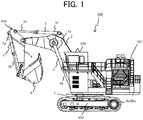
- FIG. 1 is a side view depicting the hydraulic excavator according to the present embodiment.
- a hydraulic excavator 100 includes a lower track structure 103 including crawler type track devices 8a and 8b on both side in a left-right direction, and an upper swing structure 102 swingably mounted onto the lower track structure 103.
- the lower track structure 103 and the upper swing structure 102 constitute a machine body main body of the hydraulic excavator 100.
- a cab 101 as an operating room in which an operator is seated is provided.
- the lower track structure 103 and the upper swing structure 102 are swingable through a swing motor 7 as a swing hydraulic motor.
- a base end portion of a front work implement 104 as a work device for performing, for example, excavation or the like is attached rotatably.
- the front side refers to a direction in which the operator being seated in the cab 101 is directed (leftward direction in FIG. 1 ).
- the front work implement 104 includes a boom 2 a base end portion of which is connected to the front side of the upper swing structure 102 in a vertically rotatable manner.
- the boom 2 operates through a boom cylinder 1 which is a single rod-type hydraulic cylinder.
- the boom cylinder 1 has a tip end portion of a boom rod 1b connected to the upper swing structure 102, and has a base end portion of a boom head 1a connected to the boom 2.
- a base end portion of an arm 4 is connected rotatably vertically or in a front-rear direction.
- the arm 4 operates through an arm cylinder 3 which is a single rod-type hydraulic cylinder.
- the arm cylinder 3 has a tip end portion of an arm rod 3b connected to the arm 4, and has a base end portion of the arm head 3a connected to the boom 2.
- a base end portion of a bucket 6 is connected rotatably vertically or in the front-rear direction.
- the bucket 6 operates through a bucket cylinder 5 which is a single rod-type hydraulic cylinder.
- the bucket cylinder 5 has a tip end portion of a bucket rod 5b connected to the bucket 6, and has a base end portion of a bucket head 5a connected to the arm 4.
- operating levers 30 (depicted in FIG. 2 ) as operating members for operating the boom 2, the arm 4, and the bucket 6 constituting the front work implement 104 and the upper swing structure 102.
- FIG. 2 is a schematic view depicting a hydraulic driving device for driving the hydraulic excavator 100. Note that, in FIG. 2 , only the parts concerning driving of the boom cylinder 1 and the swing motor 7 are depicted, and the parts concerning driving of the other actuators are omitted.
- a hydraulic driving device 105 includes the boom cylinder 1, the swing motor 7, a closed circuit pump 11 for driving the boom cylinder 1, and a closed circuit pump 12 for driving the swing motor 7.
- the swing motor 7 includes a pair of input-output ports 7a and 7b.
- the closed circuit pumps 11 and 12 are each driven by receiving power from an engine 9 through a transmission device 10.
- the closed circuit pumps 11 and 12 each include tilting swash plate mechanism having a pair of input-output ports as flow rate regulating means, and include regulators 11a and 12a, respectively, for regulating the pump displacements by regulating the inclination angles of the swash plates.
- the regulators 11a and 12a respectively control the delivery rates and delivery directions of the closed circuit pumps 11 and 12 according to pump delivery rate command values received from a pump valve controller 40 through a control signal line.
- Delivery ports on both sides of the closed circuit pump 11 are connected to the boom cylinder 1 through lines 21 and 22 and a selector valve 23, and constitute a cylinder closed circuit C1. Delivery ports on both sides of the closed circuit pump 12 are connected to the swing motor 7 through lines 24 and 25 and a selector valve 26, and constitute a swing closed circuit C2.
- the selector valve 23 switches between communication and interruption of communication between the lines 21 and 22 by an opening-closing control command received from the pump valve controller 40 through a control signal line.
- the selector valve 26 switches between communication and interruption of communication between the lines 24 and 25 by an opening-closing control command received from the pump valve controller 40 through a control signal line.
- a flushing valve 31 is connected to the lines 21 and 22 and a tank 33.
- the flushing valve 31 is switched so as to communicate between the line with a lower pressure, of the line 21 and the line 22, and the tank 33.
- a flushing valve 32 is connected to the lines 24 and 25 and the tank 33.
- the flushing valve 32 also is switched so as to communicate between the line with a lower pressure, of the line 24 and the line 25, and the tank 33.
- a check valve 34a is provided so as to connect the tank 33 to each of the lines 21 and 22. When the pressures in the lines 21 and 22 are lowered below the pressure in the tank 33, a hydraulic operating oil is supplied from the tank 33 to the lines 21 and 22.
- a check valve 34b is provided so as to connect the tank 33 to each of the lines 24 and 25. When the pressures in the lines 24 and 25 are lowered below the pressure in the tank 33, a hydraulic operating oil is supplied from the tank 33 to the lines 24 and 25.
- Relief valves 37a and 37b are each provided so as to connect the tank 33 to each of the lines 21 and 22.
- the relief valves 37a, 37b, 38a, and 38b are opened when the pressures in the lines 21, 22, 24, and 25 exceed a preset pressure, and play the role of safety valves for discharging the hydraulic operating oil to the tank 33.
- the pump valve controller 40 is connected to a boom lever 30a and a swing lever 30b as operating levers 30 by signal lines, and is connected to the selector valves 23 and 26 and the regulators 11a and 12a of the closed circuit pumps 11 and 12 by control signal lines.
- the pump valve controller 40 determines delivery rates of the closed circuit pumps 11 and 12 based on operation amounts of the boom lever 30a and the swing lever 30b, and outputs control signals according to the delivery rates to the regulators 11a and 12a.
- the pump valve controller 40 opens the selector valves 23 and 26 to cause the hydraulic operating oil delivered respectively by the closed circuit pumps 11 and 12 to flow into the boom cylinder 1 and the swing motor 7, thereby controlling the drive of the boom cylinder 1 and the swing motor 7.
- the delivery directions of the hydraulic operating oil at the closed circuit pumps 11 and 12 are determined respectively by operating directions of the boom lever 30a and the swing lever 30b.
- the pump valve controller 40 is described taking a controller including an electric or electronic circuit as an example thereof, the pump valve controller 40 may be configured by a hydraulic circuit.
- FIG. 3 depicts an example of the inside structure of a flushing valve 31 for the cylinder closed circuit C1.
- Lines 31b, 31c, and 31d are formed in a manifold 31a.
- the lines 21 and 22, and the tank 33 in FIG. 2 are connected respectively to the lines 31b, 31c, and 31d.
- a spool 31e in which a line 31h is formed, shims 31g1 and 31g2 and springs 31f1 and 31f2 are disposed in the manifold 31a.
- the spool 31e is moved either to the left or the right, depending on the magnitude relation between the pressures in the oil chambers.
- a line 32c on the lower pressure side is connected to a line 32d through a line 32h.
- FIG. 4 depicts an example of the inside structure of a flushing valve 32 for the swing closed circuit C2.
- Lines 32b, 32c, and 32d are formed in a manifold 32a.
- the lines 24 and 25 and the tank 33 in FIG. 2 are connected respectively to the lines 32b, 32c, and 32d.
- a spool 32e in which a line 32h is formed, shims 32g1 and 32g2, and springs 32f1 and 32f2 are disposed in the manifold 32a.
- the flushing valve 32 operates similarly to the flushing valve 31 in FIG. 3 .
- a moving amount from a neutral position of the spool 32e is a stroke amount 32i.
- a thickness T2 of the shims 32g1 and 32g2 is set larger than a thickness T1 of the shims 31g1 and 31g2.
- the stroke amount 32i of the spool 32e when a differential pressure is generated between the line 32b and the line 32c in FIG. 4 is smaller than the stroke amount 31i in FIG. 3 , and, therefore, the maximum opening area between the line 32b or the line 32c and the line 32h is reduced.
- the conventional hydraulic driving device is the hydraulic driving device 105 depicted in FIG. 2 , in which the structure of the flushing valve 32 for the swing closed circuit C2 is made to be the same as that of the flushing valve 31 (depicted in FIG. 3 ) for the cylinder closed circuit C1.
- the pump valve controller 40 When an operator operates the swing lever 30b from neutral to a predetermined operation amount to thereby give an input for instructing rotational drive of the swing motor 7, the pump valve controller 40 receives the operation amount of the swing lever 30b through a signal line. Based on the operation amount of the swing lever 30b thus received, the pump valve controller 40 sets a control command value for the selector valve 26 to an open state, for connecting the closed circuit pump 12 to the swing motor 7. In addition, the pump valve controller 40 sets a pump delivery rate command value for the closed circuit pump 12 to a value corresponding to the operation amount of the swing lever 30b. The pump valve controller 40 outputs the control command value and the pump delivery rate command value to the selector valve 26 and the regulator 12a of the closed circuit pump 12 through control signal lines.
- the selector valve 26 is opened, the hydraulic operating oil delivered by the closed circuit pump 12 flows into the input-output port 7a of the swing motor 7 through the selector valve 26 and the line 24, to drive the swing motor 7.
- the hydraulic operating oil flowing out of the input-output port 7b is sucked into the closed circuit pump 12 through the line 25 and the selector valve 26.
- the hydraulic operating oil delivered by the closed circuit pump 12 accelerates the inertial body of the upper swing structure 102 (depicted in FIG. 1 ) connected to the swing motor 7, and, therefore, the pressure in the line 24 which is on the hydraulic operating oil delivery side of the closed circuit pump 12 becomes higher than the pressure in the line 25.
- the flushing valve 32 is switched over so as to connect the line 25 on the low pressure side to the tank 33.
- the pump valve controller 40 receives the operation amount of the swing lever 30b through a signal line. Based on the operation amount of the swing lever 30b thus received, the pump valve controller 40 sets a control command value for the selector valve 26 to a closed state for connecting the closed circuit pump 12 to the swing motor 7. In addition, the pump valve controller 40 sets a pump delivery rate command value for the closed circuit pump 12 to a value according to the operation amount of the swing lever 30b. When the swing lever 30b is neutral, the pump delivery rate command value is 0. The pump valve controller 40 outputs the control command value and the pump delivery rate command value to the selector valve 26 and the regulator 12a of the closed circuit pump 12 through control signal lines.
- the selector valve 26 is closed, and the closed circuit pump 12 stops delivery of the hydraulic operating oil, but since the swing motor 7 continues rotating by inertial force of the upper swing structure 102 (depicted in FIG. 1 ) connected to the swing motor 7, the swing motor 7 delivers the hydraulic operating oil from the input-output port 7b into the line 25.
- the flushing valve 32 keeps a switching position at the time of starting swing, and, therefore, is connecting the line 25 to the tank 33. Accordingly, the hydraulic operating oil flowing out of the input-output port 7b is discharged to the tank 33 through the line 25 and the flushing valve 32.
- the hydraulic operating oil flowing out from the input-output port 7b of the swing motor 7 flows in the line 25, and the pressure inside the line 25 is further raised.
- the relief valve 38b is opened, and the hydraulic operating oil is discharged to the tank 33.
- the pressure inside the line 25 exceeds the pressure inside the line 24 to reach the relief pressure, the rotational speed of the swing motor 7 is decelerated, and the swing motor 7 is stopped after a predetermined time.
- the behavior of the swing motor 7 when the operator operates the swing lever 30b from neutral to a predetermined operation amount is similar to the aforementioned, and the description thereof is omitted.
- the pump valve controller 40 receives the operation amount of the swing lever 30b through a signal line. Based on the operation amount of the swing lever 30b thus received, the pump valve controller 40 sets a control command value for the selector valve 26 to a closed state for connecting the closed circuit pump 12 to the swing motor 7. In addition, the pump valve controller 40 sets a pump delivery rate command value for the closed circuit pump 12 to a value corresponding to the operation amount of the swing lever 30b. When the swing lever 30b is neutral, the pump delivery rate command value is 0. The pump valve controller 40 outputs the control command value and the pump delivery rate command value to the selector valve 26 and the regulator 12a of the closed circuit pump 12 through control signal lines.
- the selector valve 26 is closed, and the closed circuit pump 12 stops delivery of the hydraulic operating oil, but since the swing motor 7 continues rotating by inertial force possessed by the inertial body of the upper swing structure 102 (depicted in FIG. 1 ) connected to the swing motor 7, the swing motor 7 delivers the hydraulic operating oil from the input-output port 7b to the line 25.
- the flushing valve 32 keeps a switching position at the time of starting swing, and therefore, connects the line 25 to the tank 33. Therefore, the hydraulic operating oil flowing out of the input-output port 7b is discharged to the tank 33 through the line 25 and the flushing valve 32.
- the structure of the flushing valve 32 depicted in FIG. 4 is smaller in stroke amount 32i and narrower in throttle as compared to the aforementioned structure in FIG. 3 , and therefore, a rise in the pressure inside the line 25 due to pressure loss is quicker as compared to the increase in the through flow rate of the flushing valve 32. As a result, the flushing valve 32 is switched over more quickly in response to an operation of the swing lever 30b, as compared to the case to which the structure of FIG. 3 is applied.
- the rise in pressure inside the line 25 in response to the through flow rate of the flushing valve 32 depicted in FIG. 6 becomes larger as compared to the conventional example depicted in FIG. 5 .
- the timing of the rise in the pressure inside the line 25 is earlier than in the conventional example (depicted in FIG. 5 ), and the start of deceleration of the swing motor 7 is also earlier.
- the present invention enables deceleration responsiveness of the swing motor 7 to be enhanced.
- deceleration and stopping performance is important for the swing operation of the upper swing structure 102.
- a vehicle such as a dump truck
- the swing can be easily stopped above the dump truck, and work efficiency is improved.
- the construction machine 100 includes: the lower track structure 103; the upper swing structure 102 swingably mounted to the lower track structure 103; the work device 104 provided on the upper swing structure 102; the tank 33 reserving the hydraulic operating oil; the single rod-type hydraulic cylinder 1 that drives the work device 104; the swing hydraulic motor 7 that drives the upper swing structure 102; the operating device 30 that instructs operations of the work device 104 and the upper swing structure 102; the first closed circuit pump 11 including a bidirectionally tiltable pump; the second closed circuit pump 12 including a bidirectionally tiltable pump; the cylinder closed circuit C1 that connects the first closed circuit pump 11 to the single rod-type hydraulic cylinder 1 in a state of a closed circuit; the swing closed circuit C2 that connects the second closed circuit pump 12 to the swing hydraulic motor 7 in a state of a closed circuit; the first flushing valve 31 that permits the line on the low pressure side of the cylinder closed circuit C1 to communicate with the tank 33; the second flushing valve 32 that permits
- the openings and closings of the first selector valve 23 and the second selector valve 26 and the delivery rates of the first closed circuit pump 11 and the second closed circuit pump 12 are controlled according to operation signals inputted from the operating device 30, and in the construction machine 100, the minimum passage area from the second flushing valve 32 to the tank 33 when the second flushing valve 32 is fully open is smaller than the minimum passage area from the first flushing valve 31 to the tank 33 when the first flushing valve 31 is fully open.
- the present embodiment configured as above, at the time of starting swing deceleration, when the hydraulic operating oil is discharged from the pump suction side to the tank through the flushing valve (second flushing valve) 32 for the swing closed circuit C2, a large pressure loss is generated in the second flushing valve 32, whereby the pressure inside the line on the pump suction side is swiftly raised, and the second flushing valve 32 is swiftly switched over.
- the time necessary for the pressure inside the line on the pump suction side to reach the relief pressure is shortened, and, therefore, swing deceleration responsiveness is enhanced, and a good swing operability is obtained.
- the first flushing valve 31 includes: the first manifold 31a; the first spool 31e disposed inside the first manifold 31a; the first springs 31f1 and 31f2 that are disposed inside the first manifold 31a and that bias the first spool 31e; and the first shims 31g1 and 31g2 disposed between the first spool 31e and each of the first springs 31f1 and 31f2,
- the second flushing valve 32 includes: the second manifold 32a; the second spool 32e disposed inside the second manifold 32a; the second springs 32f1 and 32f2 that are disposed inside the second manifold 32a and that bias the second spool 32e; and the second shims 32g1 and 32g2 disposed between the second spool 32e and each of the second springs 32f1 and 32f2, and the thickness T2 of each of the second shims 32g1 and 32g2 in a spool axial direction is larger than the thickness T1 of each of
- FIG. 7 depicts the inside structure of a flushing valve 32 for a swing closed circuit C2 according to a second embodiment of the present invention.
- the difference from the flushing valve 32 (depicted in FIG. 4 ) for the swing closed circuit C2 according to the first embodiment is that the thickness T2 of each of the shims 32g1 and 32g2 is equal to the thickness T1 of each of the shims 31g1 and 31g2 of the flushing valve 31 (depicted in FIG. 2 ) for the cylinder closed circuit C1 and that a width W2 of the line 32h in the spool axial direction, the line 32h being formed in the spool 32e, is smaller than a width W1 of the line 31h of the flushing valve 31.
- the first flushing valve 31 has the first manifold 31a and the first spool 31e disposed inside the first manifold 31a
- the second flushing valve 32 has the second manifold 32a and the second spool 32e disposed inside the second manifold 32a
- the first tank connection line 31h for causing the line on the low pressure side of the cylinder closed circuit C1 to communicate with the tank 33 is formed at an intermediate portion of the first spool 31e
- the second tank connection line 32h for causing the line on the low pressure side of the swing closed circuit C2 to communicate with the tank 33 is formed at an intermediate portion of the second spool 32e
- the width W2 of the second tank connection line 32h in the spool axial direction is smaller than the width W1 of the first tank connection line 31h in the spool axial direction.
- the minimum passage area from the flushing valve 32 to the tank 33 when the flushing valve 32 is fully open is smaller than the minimum passage area from the flushing valve 31 to the tank 33 when the flushing valve 31 is fully open, and, therefore, like in the first embodiment, swing deceleration responsiveness is enhanced, and a good swing operability is obtained.
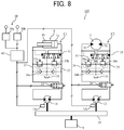
- FIG. 8 depicts a hydraulic driving device 105 according to a third embodiment of the present invention.
- the difference from the first embodiment (depicted in FIG. 2 ) is that the structure of the flushing valve 32 for the swing closed circuit C2 is the same as that of the flushing valve 31 (depicted in FIG. 3 ) for the cylinder closed circuit C1, and a throttle 41 is provided on a line for connecting the flushing valve 31 to the tank 33.
- the opening area of the throttle 41 is substantially on the order of the maximum opening area between the line 32b or the line 32c and the line 32h in the flushing valve 32 (depicted in FIG. 4 ) for the swing closed circuit C2 according to the first embodiment.
- the minimum passage area from the flushing valve 32 to the tank 33 when the flushing valve 32 is fully open is smaller than the minimum passage area from the flushing valve 31 to the tank 33 when the flushing valve 31 is fully open, like in the first embodiment.
- the hydraulic excavator 100 further includes the throttle 41 provided on the line for connecting the second flushing valve 32 to the tank 33, and the second flushing valve 32 has the same structure as that of the first flushing valve 31.
- the minimum passage area from the flushing valve 32 to the tank 33 when the flushing valve 32 is fully open is smaller than the minimum passage area from the flushing valve 31 to the tank 33 when the flushing valve 31 is fully open, and therefore, swing deceleration responsiveness is enhanced, and a good swing operability is obtained, like in the first embodiment
- flushing valve (second flushing valve 32) for the swing closed circuit C2 is the same in specifications as the flushing valve (first flushing valve 31) for the cylinder closed circuit C1, and therefore, cost can be reduced.
- the present invention is not limited to the above embodiments, but includes various modifications.
- the above-described embodiments are described in detail for easily understandably explaining the present invention, and are not necessarily limited to those including all the configurations described.
Landscapes
- Engineering & Computer Science (AREA)
- General Engineering & Computer Science (AREA)
- Mining & Mineral Resources (AREA)
- Civil Engineering (AREA)
- Structural Engineering (AREA)
- Physics & Mathematics (AREA)
- Fluid Mechanics (AREA)
- Mechanical Engineering (AREA)
- Fluid-Pressure Circuits (AREA)
- Operation Control Of Excavators (AREA)
Abstract
Description
- The present invention relates to a construction machine such as a hydraulic excavator, particularly to a construction machine that drives a single rod-type hydraulic cylinder and a swing hydraulic motor in a hydraulic closed circuit.
- In recent years, in construction machines such as a hydraulic excavator and a wheel loader, energy conservation has been an important element of development. For energy conservation of a construction machine, energy conservation of a hydraulic system itself is important; there has been investigated a hydraulic closed circuit (hereinafter referred to as a closed circuit) in which a hydraulic pump and a hydraulic actuator are connected in a state of a closed circuit, and the speed of the hydraulic actuator is controlled directly by flow rate control of the hydraulic pump. This system involves no pressure loss due to a conventional flow control valve, and in this system, energy loss is little because the pump delivers only the required flow rate. In addition, the potential energy of the hydraulic actuator and the kinetic energy at the time of deceleration can also be regenerated. Therefore, further energy conservation is possible.
- As a disclosure of conventional technology of a construction machine on which a closed circuit is mounted, there is
Patent Document 1.Patent Document 1 describes a configuration in which a hydraulic pump is connected to actuators (a boom cylinder, a swing motor, etc.) in a closed circuit and the operation speed of each of the actuators is controlled by swash plate control of the hydraulic pump. - The closed circuit described in
Patent Document 1 is provided with a flushing valve. The flushing valve is a valve for permitting a line on a low pressure side of the closed circuit to communicate with the tank, for keeping balance of the hydraulic operating oil in the closed circuit, and has a function of discharging the surplus oil on the low pressure side to the tank. - In
Patent Document 1, in the case of contracting a boom cylinder, the pump sucks in the hydraulic operating oil from the head side of the boom cylinder, and delivers the oil to the rod side. In this instance, the flushing valve is switched over so as to connect the rod side of the boom cylinder which is the low pressure side to the tank. As a result, while the hydraulic operating oil delivered by the pump flows into the rod side of the boom cylinder, the hydraulic operating oil corresponding to the pressure receiving area difference of the boom cylinder which is a single rod cylinder is discharged from the flushing valve to the tank. - On the other hand, in the case of accelerating the swing structure, the pump sucks in the hydraulic operating oil from the input/output side on one side of a swing motor, and delivers the oil to the input/output side on the other side. At this time, the flushing valve is switched over so as to connect the pump suction side which is the low pressure side to the tank. Here, when the delivery rate of the pump is reduced to decelerate the swing structure, the swing motor continues delivering the hydraulic operating oil due to the inertial energy of the swing structure, and, therefore, the pump suction side becomes a high pressure, and the flushing valve is switched over so as to connect the pump delivery side which is the low pressure side of the closed circuit to the tank. As a result, a braking pressure is exerted on the swing motor, and the swing structure is decelerated.
- Patent Document 1:
JP-2016-017602-A - In the case of a general single rod cylinder, the pressure receiving area ratio between the head side and the rod side is approximately 2:1, and, therefore, in a closed circuit driving a single rod cylinder (hereinafter referred to as a cylinder closed circuit), approximately one half of the hydraulic operating oil delivered by the pump is discharged from the flushing valve to the tank. Therefore, in the cylinder closed circuit, for reducing the pressure loss at the flushing valve, it is necessary to enlarge the size of the flushing valve.
- On the other hand, since a swing motor does not have such a pressure receiving area difference as that of the single rod cylinder, in the closed circuit driving the swing motor (hereinafter referred to as a swing closed circuit), the flow rate discharged from the flushing valve to the tank is as small as equal to or less than 1/10 times that of the cylinder closed circuit. Here, when the flushing valve of the same shape is used in the cylinder closed circuit and the swing closed circuit from the viewpoint of cost or the like, the pressure loss in the flushing valve in the swing closed circuit is smaller, so that the rise of pressure on the pump suction side (low pressure side) at the time of starting swing deceleration is delayed. As a result, the timing of switching-over of the flushing valve is delayed, and it takes time for the pressure on the pump suction side to reach the relief pressure (brake pressure). As a result, swing deceleration responsiveness is lowered, and operability is worsened.
- The present invention has been made in consideration of the above-mentioned problems. It is an object of the present invention to provide a construction machine on which a hydraulic closed circuit for driving a single rod-type hydraulic cylinder and a swing hydraulic motor is mounted and that has good swing deceleration responsiveness.
- In order to achieve the above object, the present invention provides a construction machine including: a lower track structure; an upper swing structure swingably mounted to the lower track structure; a work device provided on the upper swing structure; a tank reserving a hydraulic operating oil; a single rod-type hydraulic cylinder that drives the work device; a swing hydraulic motor that drives the upper swing structure; an operating device that gives instructions on operations of the work device and the upper swing structure; a first closed circuit pump including a bidirectionally tiltable pump; a second closed circuit pump including a bidirectionally tiltable pump; a cylinder closed circuit that connects the first closed circuit pump to the single rod-type hydraulic cylinder in a state of a closed circuit; a swing closed circuit that connects the second closed circuit pump to the swing hydraulic motor in a state of a closed circuit; a first flushing valve that permits a line on a low pressure side of the cylinder closed circuit to communicate with the tank; a second flushing valve that permits a line on a low pressure side of the swing closed circuit to communicate with the tank; a first selector valve that switches between communication and interruption of communication between the first closed circuit pump and the single rod-type hydraulic cylinder; and a second selector valve that switches between communication and interruption of communication between the second closed circuit pump and the swing hydraulic motor, and openings and closings of the first selector valve and the second selector valve and delivery rates of the first closed circuit pump and the second closed circuit pump being controlled according to operation signals inputted from the operating device, in which a minimum passage area from the second flushing valve to the tank in a case the second flushing valve is fully open is smaller than a minimum passage area from the first flushing valve to the tank in a case the first flushing valve is fully open.
- According to the present invention configured as above, at the time of starting swing deceleration, when the hydraulic operating oil is discharged from the pump suction side to the tank through the swing closed circuit flushing valve (second flushing valve), a large pressure loss is generated at the second flushing valve, whereby the pressure inside the line on the pump suction side rises, and the second flushing valve is swiftly switched over. As a result, the time taken for the pressure inside the line on the pump suction side to reach the relief pressure is shortened, and, therefore, swing deceleration responsiveness is enhanced, and good swing operability is obtained.
- According to the present invention, in a construction machine that drives a single rod-type hydraulic cylinder and a swing hydraulic motor in a hydraulic closed circuit, it is possible to enhance swing deceleration responsiveness and to obtain good swing operability.
-
-
FIG. 1 is a side view depicting a hydraulic excavator according to a first embodiment of the present invention. -
FIG. 2 is a hydraulic circuit diagram depicting a hydraulic driving device according to the first embodiment of the present invention. -
FIG. 3 is a schematic view depicting the inside structure of a flushing valve provided in a cylinder closed circuit according to the first embodiment of the present invention. -
FIG. 4 is a schematic view depicting the inside structure of a flushing valve provided in a swing closed circuit according to the first embodiment of the present invention. -
FIG. 5 is a diagram depicting an example of operation of a conventional swing closed circuit. -
FIG. 6 is a diagram depicting an example of operation of the swing closed circuit according to the first embodiment of the present invention. -
FIG. 7 is a schematic view depicting the inside structure of a flushing valve provided in a swing closed circuit according to a second embodiment of the present invention. -
FIG. 8 is a hydraulic circuit diagram depicting a hydraulic driving device according to a third embodiment of the present invention. - A construction machine according to embodiments of the present invention will be described below referring the drawings, while taking a hydraulic excavator as an example thereof. Note that the present invention is generally applicable to construction machines that include a plurality of hydraulic closed circuits having a closed circuit pump and a hydraulic cylinder connected through a selector valve in a state of a closed circuit and that include a swing closed circuit, so that the object to which to apply the present invention is not limited to the hydraulic excavator.
- A hydraulic excavator according to a first embodiment of the present invention will be described.
-
FIG. 1 is a side view depicting the hydraulic excavator according to the present embodiment. - In
FIG. 1 , ahydraulic excavator 100 includes alower track structure 103 including crawlertype track devices upper swing structure 102 swingably mounted onto thelower track structure 103. Thelower track structure 103 and theupper swing structure 102 constitute a machine body main body of thehydraulic excavator 100. - On the
upper swing structure 102, acab 101 as an operating room in which an operator is seated is provided. Thelower track structure 103 and theupper swing structure 102 are swingable through aswing motor 7 as a swing hydraulic motor. To the front side of theupper swing structure 102, a base end portion of a front work implement 104 as a work device for performing, for example, excavation or the like is attached rotatably. Here, the front side refers to a direction in which the operator being seated in thecab 101 is directed (leftward direction inFIG. 1 ). - The
front work implement 104 includes a boom 2 a base end portion of which is connected to the front side of theupper swing structure 102 in a vertically rotatable manner. The boom 2 operates through aboom cylinder 1 which is a single rod-type hydraulic cylinder. Theboom cylinder 1 has a tip end portion of aboom rod 1b connected to theupper swing structure 102, and has a base end portion of a boom head 1a connected to the boom 2. To a tip end portion of the boom 2, a base end portion of an arm 4 is connected rotatably vertically or in a front-rear direction. The arm 4 operates through anarm cylinder 3 which is a single rod-type hydraulic cylinder. Thearm cylinder 3 has a tip end portion of anarm rod 3b connected to the arm 4, and has a base end portion of thearm head 3a connected to the boom 2. To a tip end portion of the arm 4, a base end portion of abucket 6 is connected rotatably vertically or in the front-rear direction. Thebucket 6 operates through abucket cylinder 5 which is a single rod-type hydraulic cylinder. Thebucket cylinder 5 has a tip end portion of abucket rod 5b connected to thebucket 6, and has a base end portion of abucket head 5a connected to the arm 4. In thecab 101, there are disposed operating levers 30 (depicted inFIG. 2 ) as operating members for operating the boom 2, the arm 4, and thebucket 6 constituting the front work implement 104 and theupper swing structure 102. -
FIG. 2 is a schematic view depicting a hydraulic driving device for driving thehydraulic excavator 100. Note that, inFIG. 2 , only the parts concerning driving of theboom cylinder 1 and theswing motor 7 are depicted, and the parts concerning driving of the other actuators are omitted. - A
hydraulic driving device 105 includes theboom cylinder 1, theswing motor 7, aclosed circuit pump 11 for driving theboom cylinder 1, and aclosed circuit pump 12 for driving theswing motor 7. Theswing motor 7 includes a pair of input-output ports - The closed circuit pumps 11 and 12 are each driven by receiving power from an engine 9 through a
transmission device 10. The closed circuit pumps 11 and 12 each include tilting swash plate mechanism having a pair of input-output ports as flow rate regulating means, and includeregulators regulators pump valve controller 40 through a control signal line. - Delivery ports on both sides of the
closed circuit pump 11 are connected to theboom cylinder 1 throughlines selector valve 23, and constitute a cylinder closed circuit C1. Delivery ports on both sides of theclosed circuit pump 12 are connected to theswing motor 7 throughlines selector valve 26, and constitute a swing closed circuit C2. Theselector valve 23 switches between communication and interruption of communication between thelines pump valve controller 40 through a control signal line. Theselector valve 26 switches between communication and interruption of communication between thelines pump valve controller 40 through a control signal line. - A flushing
valve 31 is connected to thelines tank 33. The flushingvalve 31 is switched so as to communicate between the line with a lower pressure, of theline 21 and theline 22, and thetank 33. A flushingvalve 32 is connected to thelines tank 33. The flushingvalve 32 also is switched so as to communicate between the line with a lower pressure, of theline 24 and theline 25, and thetank 33. - A
check valve 34a is provided so as to connect thetank 33 to each of thelines lines tank 33, a hydraulic operating oil is supplied from thetank 33 to thelines check valve 34b is provided so as to connect thetank 33 to each of thelines lines tank 33, a hydraulic operating oil is supplied from thetank 33 to thelines -
Relief valves tank 33 to each of thelines relief valves lines tank 33. - The
pump valve controller 40 is connected to aboom lever 30a and aswing lever 30b as operating levers 30 by signal lines, and is connected to theselector valves regulators pump valve controller 40 determines delivery rates of the closed circuit pumps 11 and 12 based on operation amounts of theboom lever 30a and theswing lever 30b, and outputs control signals according to the delivery rates to theregulators boom lever 30a and/or theswing lever 30b is operated, thepump valve controller 40 opens theselector valves boom cylinder 1 and theswing motor 7, thereby controlling the drive of theboom cylinder 1 and theswing motor 7. The delivery directions of the hydraulic operating oil at the closed circuit pumps 11 and 12 are determined respectively by operating directions of theboom lever 30a and theswing lever 30b. Note that, in the present embodiment, thepump valve controller 40 is described taking a controller including an electric or electronic circuit as an example thereof, thepump valve controller 40 may be configured by a hydraulic circuit. - Next, the structure of the flushing valve in the present embodiment will be described.
-
FIG. 3 depicts an example of the inside structure of a flushingvalve 31 for the cylinder closed circuit C1.Lines lines tank 33 inFIG. 2 are connected respectively to thelines spool 31e in which aline 31h is formed, shims 31g1 and 31g2 and springs 31f1 and 31f2 are disposed in the manifold 31a. When a hydraulic operating oil is introduced into respective oil chambers where the springs 31f1 and 31f2 are present from thelines spool 31e is moved either to the left or the right, depending on the magnitude relation between the pressures in the oil chambers. For example, when the pressure in theline 31b is higher than that in theline 31c, the pressure in the oil chamber where the spring 31f1 is present is higher, so that thespool 31e is moved to the right. With thespool 31e moved to the right by an amount corresponding to astroke amount 31i, aline 32c on the lower pressure side is connected to aline 32d through aline 32h. -
FIG. 4 depicts an example of the inside structure of a flushingvalve 32 for the swing closed circuit C2.Lines lines tank 33 inFIG. 2 are connected respectively to thelines spool 32e in which aline 32h is formed, shims 32g1 and 32g2, and springs 32f1 and 32f2 are disposed in the manifold 32a. The flushingvalve 32 operates similarly to the flushingvalve 31 inFIG. 3 . InFIG. 4 , a moving amount from a neutral position of thespool 32e is astroke amount 32i. - Here, in the flushing
valve 32 for the swing closed circuit C2 inFIG. 4 , for making the throttle narrower than that in the flushing valve 31 (depicted inFIG. 3 ) for the cylinder closed circuit C1, a thickness T2 of the shims 32g1 and 32g2 is set larger than a thickness T1 of the shims 31g1 and 31g2. As a result, thestroke amount 32i of thespool 32e when a differential pressure is generated between theline 32b and theline 32c inFIG. 4 is smaller than thestroke amount 31i inFIG. 3 , and, therefore, the maximum opening area between theline 32b or theline 32c and theline 32h is reduced. - Next, an operation when the
swing motor 7 is driven by a conventional hydraulic driving device will be described usingFIG. 2 . Here, the conventional hydraulic driving device is thehydraulic driving device 105 depicted inFIG. 2 , in which the structure of the flushingvalve 32 for the swing closed circuit C2 is made to be the same as that of the flushing valve 31 (depicted inFIG. 3 ) for the cylinder closed circuit C1. - When an operator operates the
swing lever 30b from neutral to a predetermined operation amount to thereby give an input for instructing rotational drive of theswing motor 7, thepump valve controller 40 receives the operation amount of theswing lever 30b through a signal line. Based on the operation amount of theswing lever 30b thus received, thepump valve controller 40 sets a control command value for theselector valve 26 to an open state, for connecting theclosed circuit pump 12 to theswing motor 7. In addition, thepump valve controller 40 sets a pump delivery rate command value for theclosed circuit pump 12 to a value corresponding to the operation amount of theswing lever 30b. Thepump valve controller 40 outputs the control command value and the pump delivery rate command value to theselector valve 26 and theregulator 12a of theclosed circuit pump 12 through control signal lines. - As a result, the
selector valve 26 is opened, the hydraulic operating oil delivered by theclosed circuit pump 12 flows into the input-output port 7a of theswing motor 7 through theselector valve 26 and theline 24, to drive theswing motor 7. The hydraulic operating oil flowing out of the input-output port 7b is sucked into theclosed circuit pump 12 through theline 25 and theselector valve 26. - At this time, the hydraulic operating oil delivered by the
closed circuit pump 12 accelerates the inertial body of the upper swing structure 102 (depicted inFIG. 1 ) connected to theswing motor 7, and, therefore, the pressure in theline 24 which is on the hydraulic operating oil delivery side of theclosed circuit pump 12 becomes higher than the pressure in theline 25. The flushingvalve 32 is switched over so as to connect theline 25 on the low pressure side to thetank 33. - When the operator operates the
swing lever 30b from a predetermined operation amount to a neutral position to give an input for instructing stoppage of theswing motor 7, thepump valve controller 40 receives the operation amount of theswing lever 30b through a signal line. Based on the operation amount of theswing lever 30b thus received, thepump valve controller 40 sets a control command value for theselector valve 26 to a closed state for connecting theclosed circuit pump 12 to theswing motor 7. In addition, thepump valve controller 40 sets a pump delivery rate command value for theclosed circuit pump 12 to a value according to the operation amount of theswing lever 30b. When theswing lever 30b is neutral, the pump delivery rate command value is 0. Thepump valve controller 40 outputs the control command value and the pump delivery rate command value to theselector valve 26 and theregulator 12a of theclosed circuit pump 12 through control signal lines. - As a result, the
selector valve 26 is closed, and theclosed circuit pump 12 stops delivery of the hydraulic operating oil, but since theswing motor 7 continues rotating by inertial force of the upper swing structure 102 (depicted inFIG. 1 ) connected to theswing motor 7, theswing motor 7 delivers the hydraulic operating oil from the input-output port 7b into theline 25. In this instance, the flushingvalve 32 keeps a switching position at the time of starting swing, and, therefore, is connecting theline 25 to thetank 33. Accordingly, the hydraulic operating oil flowing out of the input-output port 7b is discharged to thetank 33 through theline 25 and the flushingvalve 32. - The state inside the swing closed circuit C2 at this time will be described using
FIG. 5 . When the operator operates theswing lever 30b from a predetermined operation amount to a neutral position, the flow rate of the hydraulic operating oil flowing to the flushingvalve 32 increases accordingly. When the through flow rate of the flushingvalve 32 increases, the pressure inside theline 25 rises due to pressure loss. On the other hand, the pressure inside theline 24 is lowered, since the input-output port 7a of theswing motor 7 sucks in the hydraulic operating oil in theline 24. When the pressure inside theline 24 is lowered below the pressure inside theline 25, the flushingvalve 32 is switched over, to connect theline 24 to thetank 33. Thereafter, the hydraulic operating oil flowing out from the input-output port 7b of theswing motor 7 flows in theline 25, and the pressure inside theline 25 is further raised. When the pressure inside theline 25 is raised to a preset pressure of therelief valve 38b (hereinafter referred to as relief pressure), therelief valve 38b is opened, and the hydraulic operating oil is discharged to thetank 33. When the pressure inside theline 25 exceeds the pressure inside theline 24 to reach the relief pressure, the rotational speed of theswing motor 7 is decelerated, and theswing motor 7 is stopped after a predetermined time. - Next, an operation when the
swing motor 7 is driven by thehydraulic driving device 105 in the present embodiment will be described usingFIG. 2 . - The behavior of the
swing motor 7 when the operator operates theswing lever 30b from neutral to a predetermined operation amount is similar to the aforementioned, and the description thereof is omitted. - When the operator operates the
swing lever 30b from a predetermined operation amount to a neutral position to give an input for instructing stoppage of theswing motor 7, thepump valve controller 40 receives the operation amount of theswing lever 30b through a signal line. Based on the operation amount of theswing lever 30b thus received, thepump valve controller 40 sets a control command value for theselector valve 26 to a closed state for connecting theclosed circuit pump 12 to theswing motor 7. In addition, thepump valve controller 40 sets a pump delivery rate command value for theclosed circuit pump 12 to a value corresponding to the operation amount of theswing lever 30b. When theswing lever 30b is neutral, the pump delivery rate command value is 0. Thepump valve controller 40 outputs the control command value and the pump delivery rate command value to theselector valve 26 and theregulator 12a of theclosed circuit pump 12 through control signal lines. - As a result, the
selector valve 26 is closed, and theclosed circuit pump 12 stops delivery of the hydraulic operating oil, but since theswing motor 7 continues rotating by inertial force possessed by the inertial body of the upper swing structure 102 (depicted inFIG. 1 ) connected to theswing motor 7, theswing motor 7 delivers the hydraulic operating oil from the input-output port 7b to theline 25. At this time, the flushingvalve 32 keeps a switching position at the time of starting swing, and therefore, connects theline 25 to thetank 33. Therefore, the hydraulic operating oil flowing out of the input-output port 7b is discharged to thetank 33 through theline 25 and the flushingvalve 32. - Next, the state inside the swing closed circuit C2 will be described using
FIG. 6 . When the operator operates theswing lever 30b from a predetermined operation amount to a neutral position, the through flow rate of the flushingvalve 32 increases accordingly. - The structure of the flushing
valve 32 depicted inFIG. 4 is smaller instroke amount 32i and narrower in throttle as compared to the aforementioned structure inFIG. 3 , and therefore, a rise in the pressure inside theline 25 due to pressure loss is quicker as compared to the increase in the through flow rate of the flushingvalve 32. As a result, the flushingvalve 32 is switched over more quickly in response to an operation of theswing lever 30b, as compared to the case to which the structure ofFIG. 3 is applied. - Thereafter, as depicted in
FIG. 6 , when the pressure inside theline 25 exceeds the pressure inside theline 24 to reach the relief pressure, the rotational speed of theswing motor 7 is decelerated, and theswing motor 7 is stopped after a predetermined time. - Since the structure of the flushing
valve 32 depicted inFIG. 4 is narrower in throttle than the structure ofFIG. 3 applied to theaforementioned flushing valve 31, the rise in pressure inside theline 25 in response to the through flow rate of the flushingvalve 32 depicted inFIG. 6 becomes larger as compared to the conventional example depicted inFIG. 5 . As a result, in response to an operation of returning theswing lever 30b to the neutral position, the timing of the rise in the pressure inside theline 25 is earlier than in the conventional example (depicted inFIG. 5 ), and the start of deceleration of theswing motor 7 is also earlier. In other words, the present invention enables deceleration responsiveness of theswing motor 7 to be enhanced. - In the
hydraulic excavator 100, deceleration and stopping performance is important for the swing operation of theupper swing structure 102. For example, when excavated soil is loaded on a vehicle such as a dump truck, it is necessary for thehydraulic excavator 100 to swing, after excavation, and carry the soil above the dump truck without dropping the soil; at this time, if swing deceleration response, or brake response is poor, the swing cannot be stopped above the dump truck, and the swing may pass the stop position above the dump truck, thereby lowering the work efficiency. - When the brake responsiveness in swing of the swing closed circuit is enhanced by the present invention, the swing can be easily stopped above the dump truck, and work efficiency is improved.
- In the first embodiment of the present invention, the construction machine 100 includes: the lower track structure 103; the upper swing structure 102 swingably mounted to the lower track structure 103; the work device 104 provided on the upper swing structure 102; the tank 33 reserving the hydraulic operating oil; the single rod-type hydraulic cylinder 1 that drives the work device 104; the swing hydraulic motor 7 that drives the upper swing structure 102; the operating device 30 that instructs operations of the work device 104 and the upper swing structure 102; the first closed circuit pump 11 including a bidirectionally tiltable pump; the second closed circuit pump 12 including a bidirectionally tiltable pump; the cylinder closed circuit C1 that connects the first closed circuit pump 11 to the single rod-type hydraulic cylinder 1 in a state of a closed circuit; the swing closed circuit C2 that connects the second closed circuit pump 12 to the swing hydraulic motor 7 in a state of a closed circuit; the first flushing valve 31 that permits the line on the low pressure side of the cylinder closed circuit C1 to communicate with the tank 33; the second flushing valve 32 that permits the line on the low pressure side of the swing closed circuit C2 to communicate with the tank 33; the first selector valve 23 that switches between communication and interruption of communication between the first closed circuit pump 11 and the single rod-type hydraulic cylinder 1; and the second selector valve 26 that switches between communication and interruption of communication between the second closed circuit pump 12 and the swing hydraulic motor 7. The openings and closings of the
first selector valve 23 and thesecond selector valve 26 and the delivery rates of the firstclosed circuit pump 11 and the secondclosed circuit pump 12 are controlled according to operation signals inputted from the operatingdevice 30, and in theconstruction machine 100, the minimum passage area from thesecond flushing valve 32 to thetank 33 when thesecond flushing valve 32 is fully open is smaller than the minimum passage area from thefirst flushing valve 31 to thetank 33 when thefirst flushing valve 31 is fully open. - According to the present embodiment configured as above, at the time of starting swing deceleration, when the hydraulic operating oil is discharged from the pump suction side to the tank through the flushing valve (second flushing valve) 32 for the swing closed circuit C2, a large pressure loss is generated in the
second flushing valve 32, whereby the pressure inside the line on the pump suction side is swiftly raised, and thesecond flushing valve 32 is swiftly switched over. As a result, the time necessary for the pressure inside the line on the pump suction side to reach the relief pressure is shortened, and, therefore, swing deceleration responsiveness is enhanced, and a good swing operability is obtained. - In addition, the
first flushing valve 31 includes: thefirst manifold 31a; thefirst spool 31e disposed inside thefirst manifold 31a; the first springs 31f1 and 31f2 that are disposed inside thefirst manifold 31a and that bias thefirst spool 31e; and the first shims 31g1 and 31g2 disposed between thefirst spool 31e and each of the first springs 31f1 and 31f2, thesecond flushing valve 32 includes: thesecond manifold 32a; thesecond spool 32e disposed inside thesecond manifold 32a; the second springs 32f1 and 32f2 that are disposed inside thesecond manifold 32a and that bias thesecond spool 32e; and the second shims 32g1 and 32g2 disposed between thesecond spool 32e and each of the second springs 32f1 and 32f2, and the thickness T2 of each of the second shims 32g1 and 32g2 in a spool axial direction is larger than the thickness T1 of each of the first shims 31g1 and 31g2. As a result, the maximum opening area of the flushingvalve 32 can be reduced without changing the shape of the manifold 32a which is cast in a die, and, therefore, cost of the flushingvalve 32 can be suppressed. -
FIG. 7 depicts the inside structure of a flushingvalve 32 for a swing closed circuit C2 according to a second embodiment of the present invention. - In
FIG. 7 , the difference from the flushing valve 32 (depicted inFIG. 4 ) for the swing closed circuit C2 according to the first embodiment is that the thickness T2 of each of the shims 32g1 and 32g2 is equal to the thickness T1 of each of the shims 31g1 and 31g2 of the flushing valve 31 (depicted inFIG. 2 ) for the cylinder closed circuit C1 and that a width W2 of theline 32h in the spool axial direction, theline 32h being formed in thespool 32e, is smaller than a width W1 of theline 31h of the flushingvalve 31. - In this way, in the present embodiment, the
first flushing valve 31 has thefirst manifold 31a and thefirst spool 31e disposed inside thefirst manifold 31a, thesecond flushing valve 32 has thesecond manifold 32a and thesecond spool 32e disposed inside thesecond manifold 32a; the firsttank connection line 31h for causing the line on the low pressure side of the cylinder closed circuit C1 to communicate with thetank 33 is formed at an intermediate portion of thefirst spool 31e, the secondtank connection line 32h for causing the line on the low pressure side of the swing closed circuit C2 to communicate with thetank 33 is formed at an intermediate portion of thesecond spool 32e; and the width W2 of the secondtank connection line 32h in the spool axial direction is smaller than the width W1 of the firsttank connection line 31h in the spool axial direction. - Also, in the present embodiment configured as above, also, the minimum passage area from the flushing
valve 32 to thetank 33 when the flushingvalve 32 is fully open is smaller than the minimum passage area from the flushingvalve 31 to thetank 33 when the flushingvalve 31 is fully open, and, therefore, like in the first embodiment, swing deceleration responsiveness is enhanced, and a good swing operability is obtained. -
FIG. 8 depicts ahydraulic driving device 105 according to a third embodiment of the present invention. - In
FIG. 8 , the difference from the first embodiment (depicted inFIG. 2 ) is that the structure of the flushingvalve 32 for the swing closed circuit C2 is the same as that of the flushing valve 31 (depicted inFIG. 3 ) for the cylinder closed circuit C1, and athrottle 41 is provided on a line for connecting the flushingvalve 31 to thetank 33. Here, the opening area of thethrottle 41 is substantially on the order of the maximum opening area between theline 32b or theline 32c and theline 32h in the flushing valve 32 (depicted inFIG. 4 ) for the swing closed circuit C2 according to the first embodiment. As a result, the minimum passage area from the flushingvalve 32 to thetank 33 when the flushingvalve 32 is fully open is smaller than the minimum passage area from the flushingvalve 31 to thetank 33 when the flushingvalve 31 is fully open, like in the first embodiment. - In this way, the
hydraulic excavator 100 according to the present embodiment further includes thethrottle 41 provided on the line for connecting thesecond flushing valve 32 to thetank 33, and thesecond flushing valve 32 has the same structure as that of thefirst flushing valve 31. - Also, in the present embodiment configured as above, the minimum passage area from the flushing
valve 32 to thetank 33 when the flushingvalve 32 is fully open is smaller than the minimum passage area from the flushingvalve 31 to thetank 33 when the flushingvalve 31 is fully open, and therefore, swing deceleration responsiveness is enhanced, and a good swing operability is obtained, like in the first embodiment - Further, the flushing valve (second flushing valve 32) for the swing closed circuit C2 is the same in specifications as the flushing valve (first flushing valve 31) for the cylinder closed circuit C1, and therefore, cost can be reduced.
- While the embodiments of the present invention have been described in detail above, the present invention is not limited to the above embodiments, but includes various modifications. For example, the above-described embodiments are described in detail for easily understandably explaining the present invention, and are not necessarily limited to those including all the configurations described. Further, it is possible to add a part of the configuration of other embodiment to the configuration of a certain embodiment, and a part of the configuration of a certain embodiment may be deleted or may be replaced by a part of other embodiment.
-
- 1:
- Boom cylinder (single rod-type hydraulic cylinder)
- 1a:
- Boom head
- 1b:
- Boom rod
- 2:
- Boom
- 3:
- Arm cylinder
- 3a:
- Arm head
- 3b:
- Arm rod
- 4:
- Arm
- 5:
- Bucket cylinder
- 5a:
- Bucket head
- 5b:
- Bucket rod
- 6:
- Bucket
- 7:
- Swing motor (swing hydraulic motor)
- 7a, 7b:
- Input-output port
- 8a, 8b:
- Track device
- 9:
- Engine
- 10:
- Transmission device
- 11:
- Closed circuit pump (first closed circuit pump)
- 12:
- Closed circuit pump (second closed circuit pump)
- 11a, 12a:
- Regulator
- 21, 22, 24, 25:
- Line
- 23:
- Selector valve (first selector valve)
- 26:
- Selector valve (second selector valve)
- 30:
- Operating lever (operating device)
- 30a:
- Boom lever
- 30b:
- Swing lever
- 31:
- Flushing valve (first flushing valve)
- 32:
- Flushing valve (second flushing valve)
- 31b, 31c, 31d:
- Line
- 31e:
- Spool (first spool)
- 31g1, 31g2:
- Shim (first shim)
- 31f1, 31f2:
- Spring (first spring)
- 31h:
- Line (first tank connection line)
- 31i:
- Stroke amount
- 32b, 32c, 32d:
- Line
- 32e:
- Spool (second spool)
- 32g1, 32g2:
- Shim (second shim)
- 32f1, 32f2:
- Spring (second spring)
- 32h:
- Line (second tank connection line)
- 32i:
- Stroke amount
- 33:
- Tank
- 34a, 34b:
- Check valve
- 37a, 37b, 38a, 38b:
- Relief valve
- 40:
- Pump valve controller
- 100:
- Hydraulic excavator (construction machine)
- 101:
- Cab
- 102:
- Upper swing structure
- 104:
- Front work implement (work device)
- 105:
- Hydraulic driving device
Claims (4)
- A construction machine comprising:a lower track structure;an upper swing structure swingably mounted to the lower track structure;a work device provided on the upper swing structure;a tank reserving a hydraulic operating oil;a single rod-type hydraulic cylinder that drives the work device;a swing hydraulic motor that drives the upper swing structure;an operating device that gives instructions on operations of the work device and the upper swing structure;a first closed circuit pump including a bidirectionally tiltable pump;a second closed circuit pump including a bidirectionally tiltable pump;a cylinder closed circuit that connects the first closed circuit pump to the single rod-type hydraulic cylinder in a state of a closed circuit;a swing closed circuit that connects the second closed circuit pump to the swing hydraulic motor in a state of a closed circuit;a first flushing valve that permits a line on a low pressure side of the cylinder closed circuit to communicate with the tank;a second flushing valve that permits a line on a low pressure side of the swing closed circuit to communicate with the tank;a first selector valve that switches between communication and interruption of communication between the first closed circuit pump and the single rod-type hydraulic cylinder; anda second selector valve that switches between communication and interruption of communication between the second closed circuit pump and the swing hydraulic motor, andopenings and closings of the first selector valve and the second selector valve and delivery rates of the first closed circuit pump and the second closed circuit pump being controlled according to operation signals inputted from the operating device,wherein a minimum passage area from the second flushing valve to the tank in a case the second flushing valve is fully open is smaller than a minimum passage area from the first flushing valve to the tank in a case the first flushing valve is fully open.
- The construction machine according to claim 1,
wherein the first flushing valve has a first manifold, a first spool disposed in the first manifold, a first spring that is disposed in the first manifold and that biases the first spool, and a first shim disposed between the first spool and the first spring,
the second flushing valve has a second manifold, a second spool disposed in the second manifold, a second spring that is disposed in the second manifold and that biases the second spool, and a second shim disposed between the second spool and the second spring, and
a thickness of the second shim in a spool axial direction is larger than a thickness of the first shim in a spool axial direction. - The construction machine according to claim 1,
wherein the first flushing valve has a first manifold, and a first spool disposed in the first manifold,
the second flushing valve has a second manifold, and a second spool disposed in the second manifold,
a first tank connection line for permitting a line on a low pressure side of the cylinder closed circuit to communicate with the tank is formed at an intermediate portion of the first spool,
a second tank connection line for permitting a line on a low pressure side of the swing closed circuit to communicate with the tank is formed at an intermediate portion of the second spool, and
a width of the second tank connection line in a spool axial direction is smaller than a width of the first tank connection line in a spool axial direction. - The construction machine according to claim 1, further comprising:a throttle provided on a line connecting the second flushing valve to the tank,wherein the second flushing valve has a same structure as that of the first flushing valve.
Applications Claiming Priority (2)
| Application Number | Priority Date | Filing Date | Title |
|---|---|---|---|
| JP2019011592A JP7090567B2 (en) | 2019-01-25 | 2019-01-25 | Construction machinery |
| PCT/JP2019/043331 WO2020152937A1 (en) | 2019-01-25 | 2019-11-05 | Construction machine |
Publications (3)
| Publication Number | Publication Date |
|---|---|
| EP3835598A1 true EP3835598A1 (en) | 2021-06-16 |
| EP3835598A4 EP3835598A4 (en) | 2022-04-27 |
| EP3835598B1 EP3835598B1 (en) | 2025-05-07 |
Family
ID=71736111
Family Applications (1)
| Application Number | Title | Priority Date | Filing Date |
|---|---|---|---|
| EP19911321.8A Active EP3835598B1 (en) | 2019-01-25 | 2019-11-05 | Construction machine |
Country Status (5)
| Country | Link |
|---|---|
| US (1) | US11859367B2 (en) |
| EP (1) | EP3835598B1 (en) |
| JP (1) | JP7090567B2 (en) |
| CN (1) | CN112585361B (en) |
| WO (1) | WO2020152937A1 (en) |
Families Citing this family (2)
| Publication number | Priority date | Publication date | Assignee | Title |
|---|---|---|---|---|
| US11941646B2 (en) | 2020-09-11 | 2024-03-26 | The Nielsen Company (Us), Llc | Methods and apparatus to estimate population reach from marginals |
| WO2022170204A1 (en) | 2021-02-08 | 2022-08-11 | The Nielsen Company (Us), Llc | Methods and apparatus to perform computer-based monitoring of audiences of network-based media by using information theory to estimate intermediate level unions |
Family Cites Families (17)
| Publication number | Priority date | Publication date | Assignee | Title |
|---|---|---|---|---|
| US4369625A (en) * | 1979-06-27 | 1983-01-25 | Hitachi Construction Machinery Co., Ltd. | Drive system for construction machinery and method of controlling hydraulic circuit means thereof |
| JPS57144344A (en) * | 1981-03-02 | 1982-09-06 | Hitachi Constr Mach Co Ltd | Flushing valve |
| JPS58144104U (en) * | 1982-03-24 | 1983-09-28 | 日立建機株式会社 | Braking device for hydraulically driven machines |
| JPS59208205A (en) * | 1983-05-11 | 1984-11-26 | Hitachi Constr Mach Co Ltd | Flushing valve |
| JP3751403B2 (en) * | 1997-03-27 | 2006-03-01 | ボッシュ・レックスロス株式会社 | Displacement constant control device for variable displacement hydraulic pump |
| CN201428169Y (en) * | 2009-05-15 | 2010-03-24 | 王多云 | High efficient water-saving flushing valve |
| US9683588B2 (en) * | 2012-01-31 | 2017-06-20 | Hitachi Construction Machinery Co., Ltd. | Hydraulic closed circuit system |
| JP5857004B2 (en) * | 2013-07-24 | 2016-02-10 | 日立建機株式会社 | Energy recovery system for construction machinery |
| JP6430735B2 (en) | 2014-07-09 | 2018-11-28 | 日立建機株式会社 | Drive device for work machine |
| JP6476074B2 (en) * | 2015-06-03 | 2019-02-27 | 日立建機株式会社 | Work machine |
| JP6615138B2 (en) * | 2017-03-01 | 2019-12-04 | 日立建機株式会社 | Construction machine drive |
| JP6731373B2 (en) * | 2017-03-30 | 2020-07-29 | 日立建機株式会社 | Construction machinery |
| JP6975036B2 (en) * | 2017-12-28 | 2021-12-01 | 日立建機株式会社 | Work machine |
| JP6934454B2 (en) * | 2018-06-25 | 2021-09-15 | 日立建機株式会社 | Construction machinery |
| CN108757624B (en) * | 2018-08-01 | 2023-11-28 | 本钢板材股份有限公司 | A differential speed increasing circuit for oil cylinder relief valve |
| JP7302986B2 (en) * | 2019-02-28 | 2023-07-04 | 日立建機株式会社 | construction machinery |
| JP6998493B2 (en) * | 2019-03-06 | 2022-01-18 | 日立建機株式会社 | Construction machinery |
-
2019
- 2019-01-25 JP JP2019011592A patent/JP7090567B2/en active Active
- 2019-11-05 CN CN201980054772.4A patent/CN112585361B/en active Active
- 2019-11-05 US US17/275,064 patent/US11859367B2/en active Active
- 2019-11-05 EP EP19911321.8A patent/EP3835598B1/en active Active
- 2019-11-05 WO PCT/JP2019/043331 patent/WO2020152937A1/en not_active Ceased
Also Published As
| Publication number | Publication date |
|---|---|
| EP3835598B1 (en) | 2025-05-07 |
| CN112585361B (en) | 2022-11-18 |
| WO2020152937A1 (en) | 2020-07-30 |
| JP2020118260A (en) | 2020-08-06 |
| EP3835598A4 (en) | 2022-04-27 |
| US20220056667A1 (en) | 2022-02-24 |
| US11859367B2 (en) | 2024-01-02 |
| CN112585361A (en) | 2021-03-30 |
| JP7090567B2 (en) | 2022-06-24 |
Similar Documents
| Publication | Publication Date | Title |
|---|---|---|
| US10221871B2 (en) | Construction machinery | |
| KR101932304B1 (en) | Hydraulic drive device for working machine | |
| EP1847654A2 (en) | Straight traveling hydraulic circuit | |
| EP2660478B1 (en) | Boom-swivel compound drive hydraulic control system of construction machine | |
| WO2005019656A1 (en) | Hydraulic drrive control device | |
| CN114207293B (en) | Hydraulic systems for construction machinery | |
| US7048515B2 (en) | Hydraulic drive system and method using a fuel injection control unit | |
| WO2005042983A1 (en) | Hydraulic system for a work machine | |
| WO2019054366A1 (en) | Hydraulic drive system for construction machine | |
| JPS6225882B2 (en) | ||
| EP1860243B1 (en) | Apparatus for increasing operation speed of boom on excavator | |
| WO2021039286A1 (en) | Hydraulic system for construction machinery | |
| EP3835598B1 (en) | Construction machine | |
| US5493950A (en) | Variable priority device for swing motor in heavy construction equipment | |
| EP1398512A1 (en) | Hydraulic driving unit for working machine, and method of hydraulic drive | |
| JP4715400B2 (en) | Hydraulic control equipment for construction machinery | |
| JPH0841933A (en) | Hydraulic controller for excavator | |
| CN108779786B (en) | Work vehicle and hydraulic control method | |
| JP2721383B2 (en) | Hydraulic circuit of work machine | |
| JP2002317471A (en) | Hydraulic excavator hydraulic control circuit | |
| JP7152968B2 (en) | hydraulic excavator drive system | |
| JP3205910B2 (en) | Operation control device of multiple actuators by single variable displacement pump | |
| CN116057283A (en) | work machinery | |
| EP4006358B1 (en) | Construction machine | |
| US20240279907A1 (en) | Hydraulic control system in working machines |
Legal Events
| Date | Code | Title | Description |
|---|---|---|---|
| STAA | Information on the status of an ep patent application or granted ep patent |
Free format text: STATUS: THE INTERNATIONAL PUBLICATION HAS BEEN MADE |
|
| PUAI | Public reference made under article 153(3) epc to a published international application that has entered the european phase |
Free format text: ORIGINAL CODE: 0009012 |
|
| STAA | Information on the status of an ep patent application or granted ep patent |
Free format text: STATUS: REQUEST FOR EXAMINATION WAS MADE |
|
| 17P | Request for examination filed |
Effective date: 20210310 |
|
| AK | Designated contracting states |
Kind code of ref document: A1 Designated state(s): AL AT BE BG CH CY CZ DE DK EE ES FI FR GB GR HR HU IE IS IT LI LT LU LV MC MK MT NL NO PL PT RO RS SE SI SK SM TR |
|
| A4 | Supplementary search report drawn up and despatched |
Effective date: 20220324 |
|
| RIC1 | Information provided on ipc code assigned before grant |
Ipc: F15B 11/17 20060101ALI20220319BHEP Ipc: F15B 11/08 20060101AFI20220319BHEP |
|
| DAV | Request for validation of the european patent (deleted) | ||
| DAX | Request for extension of the european patent (deleted) | ||
| GRAP | Despatch of communication of intention to grant a patent |
Free format text: ORIGINAL CODE: EPIDOSNIGR1 |
|
| STAA | Information on the status of an ep patent application or granted ep patent |
Free format text: STATUS: GRANT OF PATENT IS INTENDED |
|
| INTG | Intention to grant announced |
Effective date: 20241202 |
|
| GRAS | Grant fee paid |
Free format text: ORIGINAL CODE: EPIDOSNIGR3 |
|
| GRAA | (expected) grant |
Free format text: ORIGINAL CODE: 0009210 |
|
| STAA | Information on the status of an ep patent application or granted ep patent |
Free format text: STATUS: THE PATENT HAS BEEN GRANTED |
|
| AK | Designated contracting states |
Kind code of ref document: B1 Designated state(s): AL AT BE BG CH CY CZ DE DK EE ES FI FR GB GR HR HU IE IS IT LI LT LU LV MC MK MT NL NO PL PT RO RS SE SI SK SM TR |
|
| REG | Reference to a national code |
Ref country code: GB Ref legal event code: FG4D |
|
| REG | Reference to a national code |
Ref country code: CH Ref legal event code: EP |
|
| REG | Reference to a national code |
Ref country code: DE Ref legal event code: R096 Ref document number: 602019069803 Country of ref document: DE |
|
| REG | Reference to a national code |
Ref country code: IE Ref legal event code: FG4D |
|
| REG | Reference to a national code |
Ref country code: NL Ref legal event code: MP Effective date: 20250507 |
|
| PG25 | Lapsed in a contracting state [announced via postgrant information from national office to epo] |
Ref country code: PT Free format text: LAPSE BECAUSE OF FAILURE TO SUBMIT A TRANSLATION OF THE DESCRIPTION OR TO PAY THE FEE WITHIN THE PRESCRIBED TIME-LIMIT Effective date: 20250908 Ref country code: FI Free format text: LAPSE BECAUSE OF FAILURE TO SUBMIT A TRANSLATION OF THE DESCRIPTION OR TO PAY THE FEE WITHIN THE PRESCRIBED TIME-LIMIT Effective date: 20250507 Ref country code: ES Free format text: LAPSE BECAUSE OF FAILURE TO SUBMIT A TRANSLATION OF THE DESCRIPTION OR TO PAY THE FEE WITHIN THE PRESCRIBED TIME-LIMIT Effective date: 20250507 |
|
| REG | Reference to a national code |
Ref country code: LT Ref legal event code: MG9D |
|
| PG25 | Lapsed in a contracting state [announced via postgrant information from national office to epo] |
Ref country code: NO Free format text: LAPSE BECAUSE OF FAILURE TO SUBMIT A TRANSLATION OF THE DESCRIPTION OR TO PAY THE FEE WITHIN THE PRESCRIBED TIME-LIMIT Effective date: 20250807 Ref country code: GR Free format text: LAPSE BECAUSE OF FAILURE TO SUBMIT A TRANSLATION OF THE DESCRIPTION OR TO PAY THE FEE WITHIN THE PRESCRIBED TIME-LIMIT Effective date: 20250808 |
|
| PG25 | Lapsed in a contracting state [announced via postgrant information from national office to epo] |
Ref country code: NL Free format text: LAPSE BECAUSE OF FAILURE TO SUBMIT A TRANSLATION OF THE DESCRIPTION OR TO PAY THE FEE WITHIN THE PRESCRIBED TIME-LIMIT Effective date: 20250507 Ref country code: PL Free format text: LAPSE BECAUSE OF FAILURE TO SUBMIT A TRANSLATION OF THE DESCRIPTION OR TO PAY THE FEE WITHIN THE PRESCRIBED TIME-LIMIT Effective date: 20250507 |
|
| REG | Reference to a national code |
Ref country code: AT Ref legal event code: MK05 Ref document number: 1792738 Country of ref document: AT Kind code of ref document: T Effective date: 20250507 |
|
| PG25 | Lapsed in a contracting state [announced via postgrant information from national office to epo] |
Ref country code: BG Free format text: LAPSE BECAUSE OF FAILURE TO SUBMIT A TRANSLATION OF THE DESCRIPTION OR TO PAY THE FEE WITHIN THE PRESCRIBED TIME-LIMIT Effective date: 20250507 |
|
| PG25 | Lapsed in a contracting state [announced via postgrant information from national office to epo] |
Ref country code: HR Free format text: LAPSE BECAUSE OF FAILURE TO SUBMIT A TRANSLATION OF THE DESCRIPTION OR TO PAY THE FEE WITHIN THE PRESCRIBED TIME-LIMIT Effective date: 20250507 |
|
| PG25 | Lapsed in a contracting state [announced via postgrant information from national office to epo] |
Ref country code: AT Free format text: LAPSE BECAUSE OF FAILURE TO SUBMIT A TRANSLATION OF THE DESCRIPTION OR TO PAY THE FEE WITHIN THE PRESCRIBED TIME-LIMIT Effective date: 20250507 |
|
| PG25 | Lapsed in a contracting state [announced via postgrant information from national office to epo] |
Ref country code: RS Free format text: LAPSE BECAUSE OF FAILURE TO SUBMIT A TRANSLATION OF THE DESCRIPTION OR TO PAY THE FEE WITHIN THE PRESCRIBED TIME-LIMIT Effective date: 20250807 |
|
| PG25 | Lapsed in a contracting state [announced via postgrant information from national office to epo] |
Ref country code: IS Free format text: LAPSE BECAUSE OF FAILURE TO SUBMIT A TRANSLATION OF THE DESCRIPTION OR TO PAY THE FEE WITHIN THE PRESCRIBED TIME-LIMIT Effective date: 20250907 |
|
| PG25 | Lapsed in a contracting state [announced via postgrant information from national office to epo] |
Ref country code: LV Free format text: LAPSE BECAUSE OF FAILURE TO SUBMIT A TRANSLATION OF THE DESCRIPTION OR TO PAY THE FEE WITHIN THE PRESCRIBED TIME-LIMIT Effective date: 20250507 |
|
| PG25 | Lapsed in a contracting state [announced via postgrant information from national office to epo] |
Ref country code: SM Free format text: LAPSE BECAUSE OF FAILURE TO SUBMIT A TRANSLATION OF THE DESCRIPTION OR TO PAY THE FEE WITHIN THE PRESCRIBED TIME-LIMIT Effective date: 20250507 Ref country code: DK Free format text: LAPSE BECAUSE OF FAILURE TO SUBMIT A TRANSLATION OF THE DESCRIPTION OR TO PAY THE FEE WITHIN THE PRESCRIBED TIME-LIMIT Effective date: 20250507 |
|
| PG25 | Lapsed in a contracting state [announced via postgrant information from national office to epo] |
Ref country code: CZ Free format text: LAPSE BECAUSE OF FAILURE TO SUBMIT A TRANSLATION OF THE DESCRIPTION OR TO PAY THE FEE WITHIN THE PRESCRIBED TIME-LIMIT Effective date: 20250507 |
|
| PG25 | Lapsed in a contracting state [announced via postgrant information from national office to epo] |
Ref country code: EE Free format text: LAPSE BECAUSE OF FAILURE TO SUBMIT A TRANSLATION OF THE DESCRIPTION OR TO PAY THE FEE WITHIN THE PRESCRIBED TIME-LIMIT Effective date: 20250507 |
|
| PG25 | Lapsed in a contracting state [announced via postgrant information from national office to epo] |
Ref country code: RO Free format text: LAPSE BECAUSE OF FAILURE TO SUBMIT A TRANSLATION OF THE DESCRIPTION OR TO PAY THE FEE WITHIN THE PRESCRIBED TIME-LIMIT Effective date: 20250507 Ref country code: SK Free format text: LAPSE BECAUSE OF FAILURE TO SUBMIT A TRANSLATION OF THE DESCRIPTION OR TO PAY THE FEE WITHIN THE PRESCRIBED TIME-LIMIT Effective date: 20250507 |
|
| PG25 | Lapsed in a contracting state [announced via postgrant information from national office to epo] |
Ref country code: IT Free format text: LAPSE BECAUSE OF FAILURE TO SUBMIT A TRANSLATION OF THE DESCRIPTION OR TO PAY THE FEE WITHIN THE PRESCRIBED TIME-LIMIT Effective date: 20250507 |
|
| REG | Reference to a national code |
Ref country code: DE Ref legal event code: R097 Ref document number: 602019069803 Country of ref document: DE |
|
| PLBE | No opposition filed within time limit |
Free format text: ORIGINAL CODE: 0009261 |
|
| STAA | Information on the status of an ep patent application or granted ep patent |
Free format text: STATUS: NO OPPOSITION FILED WITHIN TIME LIMIT |
|
| REG | Reference to a national code |
Ref country code: CH Ref legal event code: L10 Free format text: ST27 STATUS EVENT CODE: U-0-0-L10-L00 (AS PROVIDED BY THE NATIONAL OFFICE) Effective date: 20260318 |
|
| PGFP | Annual fee paid to national office [announced via postgrant information from national office to epo] |
Ref country code: DE Payment date: 20260128 Year of fee payment: 7 |
|
| 26N | No opposition filed |
Effective date: 20260210 |
|
| REG | Reference to a national code |
Ref country code: CH Ref legal event code: H13 Free format text: ST27 STATUS EVENT CODE: U-0-0-H10-H13 (AS PROVIDED BY THE NATIONAL OFFICE) Effective date: 20260623 |
|
| PG25 | Lapsed in a contracting state [announced via postgrant information from national office to epo] |
Ref country code: LT Free format text: LAPSE BECAUSE OF FAILURE TO SUBMIT A TRANSLATION OF THE DESCRIPTION OR TO PAY THE FEE WITHIN THE PRESCRIBED TIME-LIMIT Effective date: 20250507 |
|
| PG25 | Lapsed in a contracting state [announced via postgrant information from national office to epo] |
Ref country code: MC Free format text: LAPSE BECAUSE OF FAILURE TO SUBMIT A TRANSLATION OF THE DESCRIPTION OR TO PAY THE FEE WITHIN THE PRESCRIBED TIME-LIMIT Effective date: 20250507 |
|
| PG25 | Lapsed in a contracting state [announced via postgrant information from national office to epo] |
Ref country code: CH Free format text: LAPSE BECAUSE OF NON-PAYMENT OF DUE FEES Effective date: 20251130 Ref country code: LU Free format text: LAPSE BECAUSE OF NON-PAYMENT OF DUE FEES Effective date: 20251105 |
|
| PG25 | Lapsed in a contracting state [announced via postgrant information from national office to epo] |
Ref country code: SE Free format text: LAPSE BECAUSE OF FAILURE TO SUBMIT A TRANSLATION OF THE DESCRIPTION OR TO PAY THE FEE WITHIN THE PRESCRIBED TIME-LIMIT Effective date: 20250507 |