EP3835596A1 - Fan shroud for an electric motor assembly and motor assembly - Google Patents
Fan shroud for an electric motor assembly and motor assembly Download PDFInfo
- Publication number
- EP3835596A1 EP3835596A1 EP20212427.7A EP20212427A EP3835596A1 EP 3835596 A1 EP3835596 A1 EP 3835596A1 EP 20212427 A EP20212427 A EP 20212427A EP 3835596 A1 EP3835596 A1 EP 3835596A1
- Authority
- EP
- European Patent Office
- Prior art keywords
- approximately
- electric motor
- accordance
- fan shroud
- axial
- Prior art date
- Legal status (The legal status is an assumption and is not a legal conclusion. Google has not performed a legal analysis and makes no representation as to the accuracy of the status listed.)
- Pending
Links
Images


Classifications
-
- F—MECHANICAL ENGINEERING; LIGHTING; HEATING; WEAPONS; BLASTING
- F04—POSITIVE - DISPLACEMENT MACHINES FOR LIQUIDS; PUMPS FOR LIQUIDS OR ELASTIC FLUIDS
- F04D—NON-POSITIVE-DISPLACEMENT PUMPS
- F04D29/00—Details, component parts, or accessories
- F04D29/40—Casings; Connections of working fluid
- F04D29/52—Casings; Connections of working fluid for axial pumps
- F04D29/522—Casings; Connections of working fluid for axial pumps especially adapted for elastic fluid pumps
- F04D29/526—Details of the casing section radially opposing blade tips
-
- F—MECHANICAL ENGINEERING; LIGHTING; HEATING; WEAPONS; BLASTING
- F04—POSITIVE - DISPLACEMENT MACHINES FOR LIQUIDS; PUMPS FOR LIQUIDS OR ELASTIC FLUIDS
- F04D—NON-POSITIVE-DISPLACEMENT PUMPS
- F04D29/00—Details, component parts, or accessories
- F04D29/40—Casings; Connections of working fluid
- F04D29/52—Casings; Connections of working fluid for axial pumps
- F04D29/522—Casings; Connections of working fluid for axial pumps especially adapted for elastic fluid pumps
-
- F—MECHANICAL ENGINEERING; LIGHTING; HEATING; WEAPONS; BLASTING
- F04—POSITIVE - DISPLACEMENT MACHINES FOR LIQUIDS; PUMPS FOR LIQUIDS OR ELASTIC FLUIDS
- F04D—NON-POSITIVE-DISPLACEMENT PUMPS
- F04D19/00—Axial-flow pumps
- F04D19/002—Axial flow fans
-
- F—MECHANICAL ENGINEERING; LIGHTING; HEATING; WEAPONS; BLASTING
- F04—POSITIVE - DISPLACEMENT MACHINES FOR LIQUIDS; PUMPS FOR LIQUIDS OR ELASTIC FLUIDS
- F04D—NON-POSITIVE-DISPLACEMENT PUMPS
- F04D25/00—Pumping installations or systems
- F04D25/02—Units comprising pumps and their driving means
- F04D25/06—Units comprising pumps and their driving means the pump being electrically driven
- F04D25/0606—Units comprising pumps and their driving means the pump being electrically driven the electric motor being specially adapted for integration in the pump
-
- F—MECHANICAL ENGINEERING; LIGHTING; HEATING; WEAPONS; BLASTING
- F04—POSITIVE - DISPLACEMENT MACHINES FOR LIQUIDS; PUMPS FOR LIQUIDS OR ELASTIC FLUIDS
- F04D—NON-POSITIVE-DISPLACEMENT PUMPS
- F04D25/00—Pumping installations or systems
- F04D25/02—Units comprising pumps and their driving means
- F04D25/08—Units comprising pumps and their driving means the working fluid being air, e.g. for ventilation
-
- F—MECHANICAL ENGINEERING; LIGHTING; HEATING; WEAPONS; BLASTING
- F04—POSITIVE - DISPLACEMENT MACHINES FOR LIQUIDS; PUMPS FOR LIQUIDS OR ELASTIC FLUIDS
- F04D—NON-POSITIVE-DISPLACEMENT PUMPS
- F04D29/00—Details, component parts, or accessories
- F04D29/26—Rotors specially for elastic fluids
- F04D29/32—Rotors specially for elastic fluids for axial flow pumps
- F04D29/325—Rotors specially for elastic fluids for axial flow pumps for axial flow fans
- F04D29/329—Details of the hub
-
- F—MECHANICAL ENGINEERING; LIGHTING; HEATING; WEAPONS; BLASTING
- F04—POSITIVE - DISPLACEMENT MACHINES FOR LIQUIDS; PUMPS FOR LIQUIDS OR ELASTIC FLUIDS
- F04D—NON-POSITIVE-DISPLACEMENT PUMPS
- F04D29/00—Details, component parts, or accessories
- F04D29/40—Casings; Connections of working fluid
- F04D29/52—Casings; Connections of working fluid for axial pumps
- F04D29/54—Fluid-guiding means, e.g. diffusers
- F04D29/541—Specially adapted for elastic fluid pumps
- F04D29/542—Bladed diffusers
- F04D29/544—Blade shapes
-
- F—MECHANICAL ENGINEERING; LIGHTING; HEATING; WEAPONS; BLASTING
- F04—POSITIVE - DISPLACEMENT MACHINES FOR LIQUIDS; PUMPS FOR LIQUIDS OR ELASTIC FLUIDS
- F04D—NON-POSITIVE-DISPLACEMENT PUMPS
- F04D29/00—Details, component parts, or accessories
- F04D29/60—Mounting; Assembling; Disassembling
- F04D29/64—Mounting; Assembling; Disassembling of axial pumps
- F04D29/644—Mounting; Assembling; Disassembling of axial pumps especially adapted for elastic fluid pumps
- F04D29/646—Mounting or removal of fans
-
- F—MECHANICAL ENGINEERING; LIGHTING; HEATING; WEAPONS; BLASTING
- F04—POSITIVE - DISPLACEMENT MACHINES FOR LIQUIDS; PUMPS FOR LIQUIDS OR ELASTIC FLUIDS
- F04D—NON-POSITIVE-DISPLACEMENT PUMPS
- F04D29/00—Details, component parts, or accessories
- F04D29/66—Combating cavitation, whirls, noise, vibration or the like; Balancing
- F04D29/661—Combating cavitation, whirls, noise, vibration or the like; Balancing especially adapted for elastic fluid pumps
- F04D29/663—Sound attenuation
-
- F—MECHANICAL ENGINEERING; LIGHTING; HEATING; WEAPONS; BLASTING
- F04—POSITIVE - DISPLACEMENT MACHINES FOR LIQUIDS; PUMPS FOR LIQUIDS OR ELASTIC FLUIDS
- F04D—NON-POSITIVE-DISPLACEMENT PUMPS
- F04D29/00—Details, component parts, or accessories
- F04D29/66—Combating cavitation, whirls, noise, vibration or the like; Balancing
- F04D29/661—Combating cavitation, whirls, noise, vibration or the like; Balancing especially adapted for elastic fluid pumps
- F04D29/666—Combating cavitation, whirls, noise, vibration or the like; Balancing especially adapted for elastic fluid pumps by means of rotor construction or layout, e.g. unequal distribution of blades or vanes
-
- F—MECHANICAL ENGINEERING; LIGHTING; HEATING; WEAPONS; BLASTING
- F04—POSITIVE - DISPLACEMENT MACHINES FOR LIQUIDS; PUMPS FOR LIQUIDS OR ELASTIC FLUIDS
- F04D—NON-POSITIVE-DISPLACEMENT PUMPS
- F04D29/00—Details, component parts, or accessories
- F04D29/66—Combating cavitation, whirls, noise, vibration or the like; Balancing
- F04D29/661—Combating cavitation, whirls, noise, vibration or the like; Balancing especially adapted for elastic fluid pumps
- F04D29/667—Combating cavitation, whirls, noise, vibration or the like; Balancing especially adapted for elastic fluid pumps by influencing the flow pattern, e.g. suppression of turbulence
-
- F—MECHANICAL ENGINEERING; LIGHTING; HEATING; WEAPONS; BLASTING
- F04—POSITIVE - DISPLACEMENT MACHINES FOR LIQUIDS; PUMPS FOR LIQUIDS OR ELASTIC FLUIDS
- F04D—NON-POSITIVE-DISPLACEMENT PUMPS
- F04D29/00—Details, component parts, or accessories
- F04D29/66—Combating cavitation, whirls, noise, vibration or the like; Balancing
- F04D29/661—Combating cavitation, whirls, noise, vibration or the like; Balancing especially adapted for elastic fluid pumps
- F04D29/668—Combating cavitation, whirls, noise, vibration or the like; Balancing especially adapted for elastic fluid pumps damping or preventing mechanical vibrations
-
- H—ELECTRICITY
- H02—GENERATION; CONVERSION OR DISTRIBUTION OF ELECTRIC POWER
- H02K—DYNAMO-ELECTRIC MACHINES
- H02K7/00—Arrangements for handling mechanical energy structurally associated with dynamo-electric machines, e.g. structural association with mechanical driving motors or auxiliary dynamo-electric machines
- H02K7/14—Structural association with mechanical loads, e.g. with hand-held machine tools or fans
-
- F—MECHANICAL ENGINEERING; LIGHTING; HEATING; WEAPONS; BLASTING
- F04—POSITIVE - DISPLACEMENT MACHINES FOR LIQUIDS; PUMPS FOR LIQUIDS OR ELASTIC FLUIDS
- F04D—NON-POSITIVE-DISPLACEMENT PUMPS
- F04D29/00—Details, component parts, or accessories
- F04D29/66—Combating cavitation, whirls, noise, vibration or the like; Balancing
- F04D29/661—Combating cavitation, whirls, noise, vibration or the like; Balancing especially adapted for elastic fluid pumps
- F04D29/662—Balancing of rotors
-
- F—MECHANICAL ENGINEERING; LIGHTING; HEATING; WEAPONS; BLASTING
- F05—INDEXING SCHEMES RELATING TO ENGINES OR PUMPS IN VARIOUS SUBCLASSES OF CLASSES F01-F04
- F05D—INDEXING SCHEME FOR ASPECTS RELATING TO NON-POSITIVE-DISPLACEMENT MACHINES OR ENGINES, GAS-TURBINES OR JET-PROPULSION PLANTS
- F05D2250/00—Geometry
- F05D2250/30—Arrangement of components
- F05D2250/38—Arrangement of components angled, e.g. sweep angle
-
- F—MECHANICAL ENGINEERING; LIGHTING; HEATING; WEAPONS; BLASTING
- F05—INDEXING SCHEMES RELATING TO ENGINES OR PUMPS IN VARIOUS SUBCLASSES OF CLASSES F01-F04
- F05D—INDEXING SCHEME FOR ASPECTS RELATING TO NON-POSITIVE-DISPLACEMENT MACHINES OR ENGINES, GAS-TURBINES OR JET-PROPULSION PLANTS
- F05D2250/00—Geometry
- F05D2250/50—Inlet or outlet
- F05D2250/51—Inlet
-
- F—MECHANICAL ENGINEERING; LIGHTING; HEATING; WEAPONS; BLASTING
- F05—INDEXING SCHEMES RELATING TO ENGINES OR PUMPS IN VARIOUS SUBCLASSES OF CLASSES F01-F04
- F05D—INDEXING SCHEME FOR ASPECTS RELATING TO NON-POSITIVE-DISPLACEMENT MACHINES OR ENGINES, GAS-TURBINES OR JET-PROPULSION PLANTS
- F05D2250/00—Geometry
- F05D2250/50—Inlet or outlet
- F05D2250/52—Outlet
-
- F—MECHANICAL ENGINEERING; LIGHTING; HEATING; WEAPONS; BLASTING
- F05—INDEXING SCHEMES RELATING TO ENGINES OR PUMPS IN VARIOUS SUBCLASSES OF CLASSES F01-F04
- F05D—INDEXING SCHEME FOR ASPECTS RELATING TO NON-POSITIVE-DISPLACEMENT MACHINES OR ENGINES, GAS-TURBINES OR JET-PROPULSION PLANTS
- F05D2250/00—Geometry
- F05D2250/70—Shape
- F05D2250/71—Shape curved
- F05D2250/713—Shape curved inflexed
Landscapes
- Engineering & Computer Science (AREA)
- Mechanical Engineering (AREA)
- General Engineering & Computer Science (AREA)
- Power Engineering (AREA)
- Physics & Mathematics (AREA)
- Geometry (AREA)
- Structures Of Non-Positive Displacement Pumps (AREA)
Abstract
Description
- This application claims the benefit of
U.S. Provisional Patent Application No. 16/709,114, filed 10 December 2019 - The following disclosure relates generally to electric motor assemblies and, more particularly, a fan shroud configuration for electric motor assemblies.
- Electric motor assemblies are used in commercial refrigeration equipment, such as display cases, reach-in coolers, ice machines, and others to blow air for cooling products within the equipment. At least some known motor assemblies are relatively large with respect to the size of the equipment in which it is to be used and therefore limits placement of the motor assembly within the equipment and also the available space for products within the equipment. Additionally, at least some known motor assemblies channel a less than desired amount of air at a predetermined speed and static pressure, and are therefore less efficient. In order to channel the desired amount of air, some such known motor assemblies rotate at higher than desired speeds, which generates undesired noise.
- In one example, a fan shroud for use in a fan assembly configured to rotate about an axis is provided. The fan shroud includes a central hub, an inlet ring and a plurality of arms extending between the central hub and the inlet ring. Each arm of he plurality of arms comprises a curved radial portion extending from the central hub and a planar axial portion extending from the radial portion to the inlet ring.
- In another example, an electric motor assembly is provided. The electric motor assembly includes an electric motor, a fan assembly coupled to the electric motor and configured to rotate therewith about an axis. The electric motor assembly also includes a shroud coupled to the electric motor and extending about the fan assembly. The shroud includes a central hub coupled to the electric motor, an inlet ring, and a plurality of arms extending between the central hub and the inlet ring. Each arm of the plurality of arms includes a curved radial portion extending from the central hub and a planar axial portion extending from the radial portion to the inlet ring.
- The features, functions, and advantages that have been discussed can be achieved independently in various examples of the present disclosure or may be combined in yet other examples, further details of which can be seen with reference to the following description and drawings.
-
-
FIG. 1 is a perspective view of an exemplary electric motor assembly illustrating a shroud, an electric motor, and a fan assembly; -
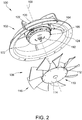
FIG. 2 is a partially exploded view of the electric motor assembly shown inFIG. 1 illustrating a rotor assembly of the electric motor; -
FIG. 3 is a cross-sectional view of the electric motor assembly shown inFIG. 1 ; -
FIG. 4 is an enlarged view of a portion of the cross-sectional view shown inFIG. 3 ; -
FIG. 5 is a top view of the electric motor assembly shown inFIG. 1 ; -
FIG. 6 is a top view of the exemplary fan assembly illustrating a hub and a plurality of blades; -
FIG. 7 is a side view of the fan assembly shown inFIG. 6 ; -
FIG. 8 is an enlarged, cross-sectional view of a portion of the fan assembly shown inFig. 7 ; -
FIG. 9 is a bottom view of the hub of the fan assembly shown inFig. 7 ; -
FIG. 10 is a bottom perspective view of the hub of the fan assembly shown inFig. 7 ; -
FIG. 11 is a cross-sectional view of the fan assembly shown inFIG. 7 ; and -
FIG. 12 is a top view of an exemplary blade of the fan assembly shown inFIG. 7 . - The implementations described herein relate to an electric motor assembly for moving air in refrigeration equipment and other applications. The electric motor assembly includes an electric motor, a fan assembly coupled to the electric motor and configured to rotate therewith about an axis, and a shroud coupled to the electric motor and extending about the fan assembly. The shroud includes a central hub coupled to the electric motor, an inlet ring, and a plurality of arms extending between the central hub and the inlet ring. Each arm of the plurality of arms includes a curved radial portion extending from the central hub and a planar axial portion extending from the radial portion to the inlet ring. The fan assembly includes a hub including a cylindrical portion and an inlet surface coupled to an inlet end of the cylindrical portion. The fan assembly also includes a plurality of blades coupled to an outer periphery of the cylindrical portion, wherein the inlet surface is tapered to direct an inlet airflow toward the plurality of blades. An outlet end of the hub includes a core ring, a first inner ring circumscribing the core ring, and a first plurality of circumferentially-spaced ribs extending between the core ring and the first inner ring. The hub also includes a second inner ring circumscribing the first inner ring and a second plurality of circumferentially-spaced ribs extending between the first inner ring and the second inner ring.
- The electric motor assembly described herein delivers an increased airflow at a higher efficiency with a lower noise level than other known air moving assemblies. The shroud arms are curved and swept in the direction of the airflow to allow the air to more easily pass through to reduce turbulence and improve efficiency. Also, the shroud arms are spaced to reduce blade tones. Similarly, the hub inlet surface is tapered to guide the incoming airflow into the blades at a predetermined angle to increase the amount of air flowing through the fan assembly. Additionally, the hub includes pluralities of ribs and rings that provide structural support to the fan assembly to maintain the fan assembly in position on the rotor and prevent vibrations to reduce noise level. Moreover, the fan assembly is easily replaceable. Furthermore, the electric motor assembly described herein occupies a smaller volume than other known air moving assemblies and therefore allows a user to utilize smaller refrigeration equipment that take up less floor space. Additionally, the smaller size of the electric motor assembly described herein provides additional space within the refrigeration equipment to place products for sale.
-
FIG. 1 is a perspective view of an exemplaryelectric motor assembly 100 illustrating ashroud 102, anelectric motor 104, and afan assembly 106.FIG. 2 is a partially exploded view ofelectric motor assembly 100 illustrating arotor assembly 105 ofelectric motor 104.FIG. 3 is a cross-sectional view ofelectric motor assembly 100.FIG. 4 is an enlarged view of a portion of the cross-sectional view shown inFIG. 3 . In the exemplary embodiment,shroud 102 is fixedly coupled toelectric motor 104 andfan assembly 106 is rotatably coupled toelectric motor 104 such that operation ofelectric motor 104 causesfan assembly 106 to rotate about arotational axis 108.Fan assembly 106 includes ahub 110 having acylindrical portion 112 and aninlet surface 114 coupled tocylindrical portion 112. Additionally,fan assembly 106 includes a plurality of circumferentially-spacedblades 116 coupled to and extending from anouter periphery 118 ofcylindrical portion 112. - In the exemplary embodiment,
shroud 102 includes acentral hub 120, a plurality ofarms 122, and aninlet ring 124.Arms 122 extend fromcentral hub 120 toinlet ring 124 and eacharm 122 includes two curves asarm 122 extends radially away fromcentral hub 120. Additionally, eacharm 122 includes aradial portion 126 extending fromcentral hub 120 and anaxial portion 128 extending fromradial portion 126 toinlet ring 124. - As best shown in
FIG. 3 ,electric motor assembly 100 includes aninlet 130 defined byinlet ring 124 and anoutlet 132 proximateradial portion 126 orarms 122. In operation, asfan assembly 106 rotates aboutaxis 108, air is drawn intoinlet 130 and is channeled throughinlet ring 124 betweenblades 116, alongmotor 104, and discharged atoutlet 132. In the exemplary embodiment,inlet ring 124 includes aninlet end 134 and anopposing outlet end 136 that define an axial ring height Hr therebetween. Similarly, eachblade 116 includes a leadingedge 138proximate inlet 130 and an opposingtrailing edge 140 that define an axial blade height Hb therebetween. As shown inFIG. 3 ,trailing edge 140 ofblades 116 is axially spaced fromoutlet end 136 ofinlet ring 124. Specifically,blades 116 andinlet ring 124 are positioned to expose a predetermined amount of blade height Hb. In one embodiment, for example whenfan assembly 106 includes a diameter of 8 inches, between approximately 17% and approximately 25% of blade height Hb is positioned axially between inletring outlet end 136 and a point alongblade trailing edge 140 where blade height Hb is at a maximum. That is, the axial distance between an axial plane aligned with inletring outlet end 136 and the point alongblade trailing edge 140 where blade height Hb is at a maximum defines an exposed blade height He (shown inFIG. 4 ) that is between approximately 17% and approximately 25% of blade height Hb. More specifically, the exposed blade height He is approximately 22% the distance of blade height Hb. In another embodiment, for example whenfan assembly 106 includes a diameter of 7 inches, the axial distance between an axial plane aligned with inletring outlet end 136 and the point alongblade trailing edge 140 where blade height Hb is at a maximum defines an exposed blade height He (shown inFIG. 4 ) that is between approximately 28% and approximately 34% of blade height Hb. More specifically, in such an embodiment, the exposed blade height He is approximately 31% the distance of blade height Hb. Positioning trailingedge 140 axially offset fromoutlet end 136 reduces tones that may be produced byblades 116 and also reduces the stall point of the airflow through the blades. - In the exemplary embodiment, as best shown in
FIG. 4 ,inlet ring 124 includes anaxial portion 142, aradial portion 144, and atransition portion 146 extending betweenaxial portion 142 andradial portion 144. As shown inFIG. 4 ,axial portion 142 may be obliquely oriented with respect toaxis 108 such that a diameter ofinlet ring 124 narrows frominlet end 134 tooutlet end 136. Alternatively,axial portion 142 is oriented parallel toaxis 108 such that the diameter ofinlet ring 124 is constant betweenends edge 138 of eachblade 116 is positioned entirely withinaxial portion 142 ofinlet ring 124 such thatleading edge 138 overlaps onlyaxial portion 142 and does not extend intotransition portion 146. Such a configuration reduces noise generated byelectric motor assembly 100 and also reduces the blade tones. - In the exemplary embodiment,
transition portion 146 is designed to increase the surface area ofinlet ring 124 that interacts with the airflow being channeled therethrough to increase the flow rate.Transition portion 146 is defined by thecurved inlet surface 147 ofinlet ring 124 atinlet 130 and defines a non-symmetrical fillet design. Specifically,inlet surface 147 is defined between afirst transition point 149 and asecond transition point 151.Transition point 149 represents the transition betweenaxial portion 142 andtransition portion 146. Similarly,transition point 151 represents the transition betweenradial portion 144 andtransition portion 146. In the exemplary embodiment,inlet surface 147 extends a first distance D1 in the radial direction betweentransition points FIG. 4 . Similarly,inlet surface 147 extends a second distance D2 in the axial direction betweentransition points FIG. 4 . In the exemplary embodiment, radial distance D1 is greater than axial distance D2. More specifically, radial distance D1 is approximately 1.5 times the length of radial distance D2. Furthermore, as shown inFIG. 4 ,inlet surface 147 extends fromtransition point 149 in an oblique direction at an angle ε, andinlet surface 147 extends fromtransition point 151 in an oblique direction at an angle δ that is smaller than angle ε. Specifically, angle ε is between approximately 25 degrees and approximately 35 degrees. More specifically, angle ε is approximately 30 degrees. Similarly, angle δ is between approximately 10 degrees and approximately 20 degrees. More specifically, angle δ is approximately 15 degrees. As such,inlet surface 147 is a continuously curved spline line betweentransition points -
FIG. 5 is a top view ofelectric motor assembly 100 illustrating the array ofarms 122 ofshroud 102. In the exemplary embodiment,radial portion 126 ofarms 122 includes a plurality of curves, whileaxial portion 128 is substantially linear. Furthermore,radial portion 126 includes a first,inner end 148 coupled tocentral hub 120 and an opposing second,outer end 150 coupled toaxial portion 128. In the exemplary embodiment, radial portion includes a radially inner firstcurved portion 152 extending fromcentral hub 120 and a radially outer secondcurved portion 154 extending between firstcurved portion 152 andaxial portion 128. Specifically, firstcurved portion 152 includes a radius of between approximately 4.0 inches and approximately 4.5 inches. More specifically, firstcurved portion 152 includes a radius of approximately 4.2 inches. Similarly, secondcurved portion 154 includes a radius of between approximately 6.6 inches and approximately 7.0 inches. More specifically, secondcurved portion 154 includes a radius of approximately 6.7 inches. Additionally,curved portions curved portion 152 is curved in a first direction with respect to the direction of rotation, and secondcurved portion 154 is curved in a second, opposite, direction with respect to the direction of rotation. - Furthermore, as shown in
FIG. 5 ,radial portion 126 defines a sweep angle α of between approximately 10 degrees and approximately 15 degrees. More specifically, in the exemplary embodiment,radial portion 126 defines a sweep angle α of approximately 12 degrees. As used herein, the term "sweep angle" is meant to describe the portion of the circumference of a circle taken up between a radial line connecting theaxis 108 and inlet end 148 ofradial portion 126 and a radialline connecting axis 108 and outlet end 150 ofradial portion 126. - The configuration resulting from the combination of
curved portions shroud 102 and also facilitates smoothing the airflow as it passes aroundarms 122 to reduce airflow turbulence and, therefore, the noise level ofelectric motor assembly 100. Additionally,arms 122 are spaced aboutcentral hub 120 such that as oneblade 116 begins to pass under onearm 122, an immediatelyadjacent blade 116 is clearing an immediatelyadjacent arm 122. Specifically, eachblade 116 includes aroot 156 that extends fromhub periphery 118 and atip 158 at distal end ofblade 116. When leadingedge 138 attip 158 of oneblade 116 begins to overlap onearm 122, trailingedge 140 attip 158 of an immediatelyadjacent blade 116 is ending its overlap with an immediatelyadjacent arm 122. Such a configuration further reduces overall noise and blade tones. -
FIG. 6 is a top view offan assembly 106illustrating hub 110 and plurality ofblades 116.FIG. 7 is a side view offan assembly 106.FIG. 8 is an enlarged view of a portion offan assembly 100 shown inFig. 7 . In the exemplary embodiment,hub 110 includescylindrical portion 112 having aninlet end 160 and anoutlet end 162. Furthermore,hub 110 includesinlet surface 114 coupled toinlet end 160. As shown inFIGs. 6-8 ,inlet surface 114 is tapered to direct airflow toward leadingedges 138 ofblades 116. Such a configuration reduces the noise level and increases the airflow volume throughfan assembly 106 for improved efficiency. - In the exemplary embodiment,
fan assembly 106 also includes ahub cap 164 configured for insertion into acap cavity 166 defined ininlet surface 114.Cavity 166 includes acentral opening 168 having aplanar portion 170. A threaded fastener (not shown), such as a bolt, is configured to be inserted throughcentral opening 168 and a corresponding faster, such as a nut, is inserted intocavity 166 to securefan assembly 106 to arotor assembly 172 ofelectric motor 104.Hub cap 164 is inserted intocavity 166 to both secure the nut in place and also to eliminate turbulent airflow by providing a smooth transition toinlet surface 114.Hub cap 164 includes a planar surface (not shown) that aligns withplanar portion 170 ofcentral opening 168 to securehub cap 164 tohub 110. Such a configuration prevents undesired removal ofhub cap 164 fromhub 110 and still allowshub cap 164 to be removed for replacement offan assembly 106. - In the exemplary embodiment,
inlet surface 114 includes afirst portion 174 extending obliquely from inlet end ofcylindrical portion 112 and asecond portion 176 extending obliquely fromfirst portion 174. As shown inFIGs. 6-8 ,first surface 174 circumscribessecond portion 176. As best shown inFIG. 8 ,first portion 174 is oriented at a first angle θ with respect to aplane 178 perpendicular toaxis 108. Similarly,second portion 176 is oriented at a second angle β with respect toplane 178. In the exemplary embodiment, first angle θ is greater than second angle β. Specifically, first angle θ offirst portion 174 is oriented between approximately 5 degrees and approximately 10 degrees with respect toplane 178. More specifically, first angle θ offirst portion 174 is oriented approximately 7 degrees with respect toplane 178. Similarly, second angle β ofsecond portion 176 is oriented between approximately 2 degrees and approximately 5 degrees with respect toplane 178. More specifically, second angle β ofsecond portion 176 is oriented approximately 3 degrees with respect toplane 178. Such a configuration provides for a smooth transition of airflow acrossinlet surface 114 and intoblades 116. -
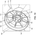
FIG. 9 is a bottom view ofoutlet end 162 ofhub 110.FIG. 10 is a perspectiveview outlet end 162.FIG. 11 is a cross-sectional view of the fan assembly shown in FIG. In the exemplary embodiment,hub 110 includes acore ring 180, a firstinner ring 182 circumscribingcore ring 180, and a first plurality of circumferentially-spacedribs 184 extending radially betweencore ring 180 and firstinner ring 182. Additionally,hub 110 includes a secondinner ring 186 circumscribing firstinner ring 182 and a second plurality of circumferentially-spacedribs 188 extending between firstinner ring 182 and secondinner ring 186. As such, second plurality ofribs 188 are positioned radially outward of first plurality ofribs 184. - In the exemplary embodiment, the quantity of ribs in first plurality of
ribs 184 is equal to the quantity of ribs in second plurality ofribs 188. Furthermore, the quantity ofblades 116 offan assembly 106 is equal to the quantity of ribs in both first andsecond pluralities rib 188 is radially aligned with a circumferential midpoint of a corresponding blade alongouter periphery 118. - As best shown in
FIG. 9 , first plurality ofribs 184 define a first radial length L1, and second plurality ofribs 188 define a second radial length L2 that is longer than the first radial length L1. Specifically, the second radial length L2 is at least twice as long as first radial length L1. Furthermore, first plurality ofribs 184 is circumferentially offset from second plurality ofribs 188. Specifically, each rib of first plurality ofribs 184 is connected to firstinner ring 182 approximately midway between adjacent ribs of second plurality ofribs 188. In operation, pluralities ofribs fan assembly 106 parallel torotor assembly 172 by distributing loads from the shaft (not shown) ofelectric motor 104 evenly amongblades 116. - In the exemplary embodiment, second plurality of
ribs 188 are deformable to facilitate balancingfan assembly 106. That is, a portion of at least onerib 188 can be removed from to balancefan assembly 106 and maintain its position parallel torotor assembly 172. In one embodiment, material can be removed from at least onerib 188 by carvingblade 188 with a tool. In another embodiment, eachrib 188 includes score marks that removal or predetermined portions ofrib 188 as needed to balancefan assembly 106. As such, material is removed fromfan assembly 106 to facilitate balancing rather than adding weights or other counterbalancing devices that may not be available. - As shown in
FIGs. 8 and9 , firstinner ring 182 includes at least onealignment device 190 extending axially therefrom. Specifically, firstinner ring 182 includes a plurality ofalignment devices 190 equally spaced about firstinner ring 182 and configured to mate with a respective one of a plurality of alignment openings 192 (shown inFIG. 2 ) onrotor assembly 172.Alignment devices 190 engagealignment openings 192 to facilitate attachingfan assembly 106 tomotor 104 and to distribute rotational loads fromrotor assembly 172. - In the exemplary embodiment,
hub 110 also includes anouter ring 194 that circumscribes secondinner ring 186 to define aradial gap 196 therebetween.Gap 194 forms a continuous circle around secondinner ring 186 and is configured to receive at least one balancing weight for balancingfan assembly 106. By either removing material from second plurality ofribs 188 or adding a weight togap 196, or both, the balance offan assembly 106 can be adjusted without adding weights toblades 116 orouter periphery 118 ofhub 110 to maintain a clean visual appearance offan assembly 106. -
Outer ring 194 forms a portion ofcylindrical portion 112 andouter periphery 118 ofhub 110. Specifically,outer ring 194 includes an axial height H1 that is equal to the axial length ofcylindrical portion 112. Additionally, as shown inFIG. 11 , secondinner ring 186 includes an axial height H2 that is less than axial height H1 ofouter ring 194. Furthermore, as shown inFIG. 11 ,outer ring 194 includes a first radial thickness T1, and secondinner ring 186 includes a second radial thickness T2 that is substantially similar to first radial thickness T1. -
FIG. 12 is a top view ofblade 116 offan assembly 106. In the exemplary embodiment,blade 112 is defined by leadingedge 138, trailingedge 140,inner profile 198 extending betweenedges root 156, andouter profile 200 extending betweenedges tip 140. As shown inFIG. 12 ,inner profile 198 is defined by a curve having a radius R1, andouter profile 200 is defined by a curve having a radius R2 that is larger than radius R1. Specifically, radius R2 ofouter profile 200 is approximately twice as large as radius R1 ofinner profile 198. More specifically, radius R1 ofinner profile 198 is between approximately 40 millimeters (mm) and approximately 60mm. Even more specifically, radius R1 ofinner profile 198 is approximately 50mm. Similarly, radius R2 ofouter profile 200 is between approximately 90mm and approximately 110mm. Even more specifically, radius R2 ofouter profile 200 is approximately 100mm. - Furthermore, in the exemplary embodiment,
inner profile 198 defines a sweep angle γ of between approximately 18 degrees and approximately 24 degrees alongroot 156 betweenedges inner profile 198 defines a sweep angle γ of approximately 21 degrees. Similarly,outer profile 200 defines a sweep angle λ of between approximately 28 degrees and approximately 32 degrees alongtip 158 betweenedges outer profile 200 defines a sweep angle λ of approximately 30 degrees. As such, the sweep angle λ ofouter profile 200 is greater than sweep angle γ ofinner profile 198. Overall,blade 116 defines a sweep angle σ of between approximately 30 degrees and approximately 35 degrees fromtip 158 of leadingedge 138 to root 156 of trailingedge 140. More specifically,blade 116 defines a sweep angle α of approximately 33 degrees fromtip 158 of leadingedge 138 to root 156 of trailingedge 140. As used herein, sweep angle is meant to describe the portion of the circumference of a circle taken up between radial lines connected ataxis 108. - In the exemplary embodiment, trailing
edge 140 is substantially planar betweeninner profile 198 andouter profile 200. Leadingedge 138 includes a radius R3 of between approximately 165mm and approximately 175mm betweeninner profile 198 andouter profile 200. More specifically, leadingedge 138 includes a radius R3 of approximately 170mm betweeninner profile 198 andouter profile 200. - Additionally, in the exemplary embodiment,
blade 116 includes a pressure side, a suction side, and a blade thickness defined therebetween. The blade thickness varies betweenleading edge 138 and trailingedge 140 such that the blade thickness is greatest approximately one third the distance from leadingedge 138 to trailingedge 140. Furthermore, eachblade 116 may include at least one are of surface roughness to retain the airflow on blade and improve efficiency. Specifically, the pressure side ofblade 116 may have one surface roughness, and the suction side ofblade 116 may include a different surface roughness. Additionally, the surface roughness may vary betweenroot 156 andtip 158 on the same side ofblade 116. Surface roughness can include either protrusions extending upward fromblade 116, or may include dimples that are formed in the surface ofblade 116. - The implementations described herein relate to an electric motor assembly for moving air in refrigeration equipment and other applications. The electric motor assembly includes an electric motor, a fan assembly coupled to the electric motor and configured to rotate therewith about an axis, and a shroud coupled to the electric motor and extending about the fan assembly. The shroud includes a central hub coupled to the electric motor, an inlet ring, and a plurality of arms extending between the central hub and the inlet ring. Each arm of the plurality of arms includes a curved radial portion extending from the central hub and a planar axial portion extending from the radial portion to the inlet ring. The fan assembly includes a hub including a cylindrical portion and an inlet surface coupled to an inlet end of the cylindrical portion. The fan assembly also includes a plurality of blades coupled to an outer periphery of the cylindrical portion, wherein the inlet surface is tapered to direct an inlet airflow toward the plurality of blades. An outlet end of the hub includes a core ring, a first inner ring circumscribing the core ring, and a first plurality of circumferentially-spaced ribs extending between the core ring and the first inner ring. The hub also includes a second inner ring circumscribing the first inner ring and a second plurality of circumferentially-spaced ribs extending between the first inner ring and the second inner ring.
- The electric motor assembly described herein delivers an increased airflow at a higher efficiency with a lower noise level than other known air moving assemblies. The shroud arms are curved and swept in the direction of the airflow to allow the air to more easily pass through to reduce turbulence and improve efficiency. Also, the shroud arms are spaced to reduce blade tones. Similarly, the hub inlet surface is tapered to guide the incoming airflow into the blades at a predetermined angle to increase the amount of air flowing through the fan assembly. Additionally, the hub includes pluralities or ribs and rings that provide structural support to the fan assembly to maintain the fan assembly in position on the rotor and prevent vibrations to result in a reduced noise level. Moreover, the fan assembly is easily replaceable. Furthermore, the electric motor assembly described herein occupies a smaller volume than other known air moving assemblies and therefore allows a user to utilize smaller refrigeration equipment to take up less floor space. Additionally, the smaller size of the electric motor assembly described herein provides additional space within the refrigeration equipment to place products for sale.
- This written description uses examples to disclose various implementations, including the best mode, and also to enable any person skilled in the art to practice the various implementations, including making and using any devices or systems and performing any incorporated methods. The patentable scope of the disclosure is defined by the claims, and may include other examples that occur to those skilled in the art. Such other examples are intended to be within the scope of the claims if they have structural elements that do not differ from the literal language of the claims, or if they include equivalent structural elements with insubstantial differences from the literal language of the claims.
Claims (14)
- A fan shroud for use in a fan assembly configured to rotate about an axis, said fan shroud comprising:a central hub;an inlet ring; anda plurality of arms extending between said central hub and said inlet ring, wherein each arm of said plurality of arms comprises a curved radial portion extending from said central hub and a planar axial portion extending from said radial portion to said inlet ring.
- The fan shroud in accordance with Claim 1, wherein said radial portion includes a plurality of curves.
- The fan shroud in accordance with Claim 1, wherein said radial portion comprises:a first end coupled to said central hub; anda second end coupled to said axial portion, wherein said radial portion comprises a sweep angle of between approximately 10 degrees and approximately 15 degrees.
- The fan shroud in accordance with Claim 3, wherein said radial portion comprises a sweep angle of approximately 12 degrees.
- The fan shroud in accordance with Claim 1, wherein said radial portion comprises a first curved portion extending from said central hub, and a second curved portion extending between said first curved portion and said axial portion.
- The fan shroud in accordance with Claim 1 or 5, wherein said first portion curved in a first direction with respect to the direction of rotation, said second portion curved in a second, opposite, direction with respect to the direction of rotation.
- The fan shroud in accordance with Claim 5, wherein said first curved portion comprises a radius of between approximately 4.0 inches and approximately 4.5 inches.
- The fan shroud in accordance with Claim 6, wherein said first curved portion comprises a radius of approximately 4.2 inches.
- The fan shroud in accordance with Claim 5, wherein said second curved portion comprises a radius of between approximately 6.6 inches and approximately 7.0 inches.
- The fan shroud in accordance with Claim 9, wherein said second curved portion comprises a radius of approximately 6.7 inches.
- An electric motor assembly comprising:an electric motor;a fan assembly coupled to said electric motor and configured to rotate about an axis; anda fan shroud according to any preceding claim, wherein said central hub is coupled to said electric motor.
- The electric motor assembly in accordance with Claim 11, wherein said fan assembly comprises a plurality of blades that each comprise a leading edge, a trailing edge, and a first axial height defined therebetween, wherein said trailing edge is axially spaced from an outlet end of said inlet ring.
- The electric motor assembly in accordance with Claim 12, wherein an axial distance between said inlet ring outlet end and a point along said trailing edge where first axial height is at a maximum is defined as an exposed blade height, wherein said exposed blade height is between approximately 17% and approximately 25% of the first axial height of said plurality of blades.
- The electric motor assembly in accordance with Claim 12, wherein an axial distance between said inlet ring outlet end and a point along said trailing edge where first axial height is at a maximum is defined as an exposed blade height, wherein said exposed blade height is between approximately 28% and approximately 34% of the first axial height of said plurality of blades.
Applications Claiming Priority (1)
| Application Number | Priority Date | Filing Date | Title |
|---|---|---|---|
| US16/709,114 US11555508B2 (en) | 2019-12-10 | 2019-12-10 | Fan shroud for an electric motor assembly |
Publications (1)
| Publication Number | Publication Date |
|---|---|
| EP3835596A1 true EP3835596A1 (en) | 2021-06-16 |
Family
ID=73747930
Family Applications (1)
| Application Number | Title | Priority Date | Filing Date |
|---|---|---|---|
| EP20212427.7A Pending EP3835596A1 (en) | 2019-12-10 | 2020-12-08 | Fan shroud for an electric motor assembly and motor assembly |
Country Status (4)
| Country | Link |
|---|---|
| US (1) | US11555508B2 (en) |
| EP (1) | EP3835596A1 (en) |
| CN (1) | CN112943701A (en) |
| MX (1) | MX2020013409A (en) |
Families Citing this family (2)
| Publication number | Priority date | Publication date | Assignee | Title |
|---|---|---|---|---|
| USD938010S1 (en) * | 2019-12-10 | 2021-12-07 | Regal Beloit America, Inc. | Fan hub |
| USD998131S1 (en) * | 2023-01-30 | 2023-09-05 | Qingdao Zhengwanxin Trading Co., Ltd. | Flush mount ceiling fan with light |
Citations (7)
| Publication number | Priority date | Publication date | Assignee | Title |
|---|---|---|---|---|
| US5466120A (en) * | 1993-03-30 | 1995-11-14 | Nippondenso Co., Ltd. | Blower with bent stays |
| USD453960S1 (en) * | 2001-01-30 | 2002-02-26 | Molded Products Company | Shroud for a fan assembly |
| US20050232765A1 (en) * | 2004-04-20 | 2005-10-20 | Masanori Watanabe | Axial flow fan |
| US20050271529A1 (en) * | 2004-04-26 | 2005-12-08 | Behr Gmbh & Co.Kg | Fan housing for a heat exchanger, particular for motor vehicles |
| JP2015108316A (en) * | 2013-12-04 | 2015-06-11 | パナソニックIpマネジメント株式会社 | Blower and outdoor unit mounting blower |
| EP3498506A1 (en) * | 2017-12-18 | 2019-06-19 | Carrier Corporation | Fan stator construction to minimize axial depth |
| CN209083612U (en) * | 2018-07-04 | 2019-07-09 | 泛仕达机电股份有限公司 | A kind of blower and its integrated molding installation frame structure |
Family Cites Families (119)
| Publication number | Priority date | Publication date | Assignee | Title |
|---|---|---|---|---|
| US2115527A (en) | 1936-10-08 | 1938-04-26 | Airmaster Corp | Mounting for exhaust fans |
| US3937189A (en) * | 1974-01-28 | 1976-02-10 | International Harvester Company | Fan shroud exit structure |
| DE3431459A1 (en) | 1984-01-14 | 1985-07-18 | Byung Eun Daegu Yoo | Fan |
| JP2572460B2 (en) | 1989-10-27 | 1997-01-16 | 日本電装株式会社 | Fan for blower |
| USD324364S (en) | 1990-03-01 | 1992-03-03 | Hannon R Douglas | Three-blade propeller |
| USD324201S (en) | 1990-03-01 | 1992-02-25 | Hannon R Douglas | Three-blade propeller |
| DE4215504A1 (en) | 1992-05-12 | 1993-11-18 | Bosch Gmbh Robert | Small commutator motor |
| EP0569863B1 (en) * | 1992-05-15 | 2000-03-29 | Siemens Canada Limited | Low axial profile, axial flow fan |
| US5423660A (en) * | 1993-06-17 | 1995-06-13 | Airflow Research And Manufacturing Corporation | Fan inlet with curved lip and cylindrical member forming labyrinth seal |
| USD368772S (en) | 1993-10-08 | 1996-04-09 | Harries Liao | Fan wheel |
| US6139265A (en) * | 1996-05-01 | 2000-10-31 | Valeo Thermique Moteur | Stator fan |
| JPH09317686A (en) | 1996-05-29 | 1997-12-09 | Daikin Ind Ltd | Fan for blower and rotation balance adjusting method thereof |
| KR100548036B1 (en) * | 1998-12-31 | 2006-05-09 | 한라공조주식회사 | Axial fan shroud assembly with guide vane for axial fan and its guide vane |
| KR100332539B1 (en) * | 1998-12-31 | 2002-04-13 | 신영주 | Axial flow fan |
| US6118198A (en) * | 1999-03-25 | 2000-09-12 | General Electric Company | Electric motor with ice out protection |
| US6435817B1 (en) * | 2000-06-20 | 2002-08-20 | General Electric Company | Methods and apparatus for reducing vibrations induced within fan assemblies |
| USD454947S1 (en) | 2000-06-29 | 2002-03-26 | Agilent Technologies, Inc. | Cooling device |
| DE10245971A1 (en) | 2002-09-30 | 2004-04-01 | Ebm Werke Gmbh & Co. Kg | Electric motor with screwless plug-in assembly |
| USD486905S1 (en) | 2002-12-13 | 2004-02-17 | Datech Technology Co., Ltd. | Fan blade |
| USD566829S1 (en) | 2003-03-27 | 2008-04-15 | Research Foundation Of The University Of Central Florida, Inc. | High efficiency air conditioner condenser twisted fan blades and hub |
| CN1288349C (en) * | 2003-03-28 | 2006-12-06 | 三星电子株式会社 | Axial fan component element |
| TW566837U (en) | 2003-04-23 | 2003-12-11 | Delta Electronics Inc | Fan motor structure |
| KR100937929B1 (en) * | 2003-07-01 | 2010-01-21 | 한라공조주식회사 | Stator of Axial flow fan shroud |
| USD507641S1 (en) | 2003-08-20 | 2005-07-19 | Delta Electronics Inc. | Impeller |
| US7156615B2 (en) * | 2003-08-21 | 2007-01-02 | Siemens Vdo Automotive Inc. | Fan shroud structure for reducing resonance, improving stiffness and manufacturability |
| USD507343S1 (en) | 2003-08-21 | 2005-07-12 | Delta Electronics Inc. | Impeller |
| TWM243572U (en) | 2003-10-07 | 2004-09-11 | Datech Technology Co Ltd | Hub of fan wheel with improved attachment for metal case |
| USD509584S1 (en) | 2003-10-08 | 2005-09-13 | Datech Technology Co., Ltd. | Fan wheel with hub fastener |
| USD509583S1 (en) | 2004-02-19 | 2005-09-13 | Hunter Fan Company | Ceiling fan motor housing |
| US20050186070A1 (en) * | 2004-02-23 | 2005-08-25 | Ling-Zhong Zeng | Fan assembly and method |
| USD513799S1 (en) | 2004-03-29 | 2006-01-24 | Datech Technology Co., Ltd. | Fan housing |
| USD515688S1 (en) | 2004-08-02 | 2006-02-21 | Datech Technology Co., Ltd. | Fan blade |
| ITBO20040507A1 (en) | 2004-08-05 | 2004-11-05 | Spal Srl | AXIAL FLOW FAN |
| US7448856B2 (en) | 2004-09-24 | 2008-11-11 | Carrier Corporation | Fan |
| USD558324S1 (en) | 2005-02-14 | 2007-12-25 | Sunonwealth Electric Machine Industry Co., Ltd. | Overlapping fan-blade structure for a fan wheel |
| EP1732375B1 (en) | 2005-06-10 | 2009-08-26 | ebm-papst St. Georgen GmbH & Co. KG | Apparatus fan |
| DE202005010000U1 (en) | 2005-06-23 | 2006-11-09 | Ebm-Papst Mulfingen Gmbh & Co. Kg | Rotor with fan wheel for an electronically commutated electric motor |
| US7309207B2 (en) * | 2005-08-29 | 2007-12-18 | Siemens Vdo Automotive Canada Inc. | Fan shroud structure reinforcement to reduce or eliminate warping and distortion |
| US20070140844A1 (en) * | 2005-12-19 | 2007-06-21 | Nidec Corporation | Axial Flow Fan |
| US8197204B2 (en) * | 2005-12-23 | 2012-06-12 | Behr Gmbh & Co. Kg | Fan system, heat exchanger module, method for manufacturing a fan system and/or a heat exchanger module |
| USD594552S1 (en) | 2006-05-12 | 2009-06-16 | University Of Central Florida Research Foundation, Inc. | Fan blade |
| JP4844877B2 (en) | 2006-05-29 | 2011-12-28 | 日本電産株式会社 | Series axial fan and axial fan |
| USD559968S1 (en) | 2006-06-08 | 2008-01-15 | Delta Electronics Inc. | Fan blade |
| USD560789S1 (en) | 2006-06-08 | 2008-01-29 | Delta Electronics Inc. | Fan blade |
| US7594800B2 (en) | 2006-07-31 | 2009-09-29 | General Electric Company | Ventilation assembly for wind turbine rotor hub |
| DE202006011899U1 (en) | 2006-08-03 | 2007-12-13 | Ebm-Papst Mulfingen Gmbh & Co. Kg | fan wheel |
| DE202006011898U1 (en) | 2006-08-03 | 2007-12-13 | Ebm-Papst Mulfingen Gmbh & Co. Kg | fan blade |
| USD570996S1 (en) | 2006-09-25 | 2008-06-10 | Pax Scientific, Inc. | Rotor |
| USD564653S1 (en) | 2006-11-22 | 2008-03-18 | Japan Servo Co., Ltd. | Propeller for an axial flow fan |
| USD570999S1 (en) | 2006-11-22 | 2008-06-10 | Pax Scientific, Inc. | Rotor |
| USD561888S1 (en) | 2006-12-28 | 2008-02-12 | Foxconn Technology Co., Ltd. | Impeller |
| USD571000S1 (en) | 2007-04-24 | 2008-06-10 | Foxconn Technology Co., Ltd. | Fan impeller |
| TWM337636U (en) | 2007-12-12 | 2008-08-01 | Taiwei Fan Technology Co Ltd | An assembled miniature axial-flow fan |
| CN201180678Y (en) | 2008-01-25 | 2009-01-14 | 台达电子工业股份有限公司 | Dynamic balance regulated fan structure |
| USD626643S1 (en) | 2008-03-13 | 2010-11-02 | Minebea Co., Ltd. | Wavy fan blade |
| USD585130S1 (en) | 2008-06-27 | 2009-01-20 | Pax Scientific, Inc. | Rotor |
| USD654997S1 (en) | 2008-12-22 | 2012-02-28 | Spal Automotive S.R.L. | Fan |
| DE202009001033U1 (en) | 2009-01-27 | 2010-06-24 | Ebm-Papst Mulfingen Gmbh & Co. Kg | Electric motor with cooling fan effect |
| CN201606274U (en) | 2009-07-17 | 2010-10-13 | 郭建春 | Novel axial flow fan |
| WO2011038884A1 (en) | 2009-10-03 | 2011-04-07 | Ebm-Papst St. Georgen Gmbh & Co. Kg | Cross-flow fan |
| USD665895S1 (en) | 2009-10-13 | 2012-08-21 | Novenco A/S | Rotor for a ventilator with six blades |
| US8353671B2 (en) | 2009-10-15 | 2013-01-15 | Asia Vital Components Co., Ltd. | Fan with pressurizing structure |
| USD644316S1 (en) | 2009-11-19 | 2011-08-30 | Spal Automotive S.R.L. | Blade of an axial fan |
| USD620096S1 (en) | 2009-12-14 | 2010-07-20 | James Ted Underwood | Spinner fan |
| TWI418707B (en) | 2010-09-03 | 2013-12-11 | Delta Electronics Inc | Fan and manufacturing method therefor |
| TWI464328B (en) | 2010-11-05 | 2014-12-11 | Delta Electronics Inc | Fan structure |
| USD645134S1 (en) | 2010-11-19 | 2011-09-13 | Micro-Star International Corporation Limited | Fan blade |
| TWI443262B (en) | 2010-12-29 | 2014-07-01 | Delta Electronics Inc | Fan and impeller thereof |
| EP2691655B1 (en) | 2011-03-26 | 2016-05-18 | ebm-papst St. Georgen GmbH & Co. KG | Diagonal fan |
| WO2012130404A1 (en) | 2011-03-26 | 2012-10-04 | Ebm-Papst St. Georgen Gmbh & Co. Kg | Diagonal fan having active engine cooling |
| EP2549116B1 (en) | 2011-07-22 | 2013-10-16 | ebm-papst Mulfingen GmbH & Co. KG | Axial ventilator with additional flow channel |
| EP2771581B1 (en) | 2011-10-25 | 2018-12-26 | ebm-papst Mulfingen GmbH & Co. KG | Axial ventilator wheel |
| DE102012000376B4 (en) | 2012-01-12 | 2013-08-14 | Ebm-Papst St. Georgen Gmbh & Co. Kg | Axial or diagonal fan |
| DE102012100628A1 (en) | 2012-01-25 | 2013-07-25 | Ebm-Papst Mulfingen Gmbh & Co. Kg | Paddle wheel with intumescent coating |
| CN103573717B (en) | 2012-07-24 | 2018-06-12 | 德昌电机(深圳)有限公司 | Fan and its impeller |
| DE202012013625U1 (en) | 2012-08-11 | 2018-08-21 | Ebm-Papst St. Georgen Gmbh & Co. Kg | Electronically commutated external rotor motor |
| CN202900765U (en) | 2012-11-03 | 2013-04-24 | 苏州顶裕节能设备有限公司 | Spherical shaft end cover device for centrifugal impellers |
| USD726897S1 (en) | 2013-02-25 | 2015-04-14 | Wellington Drive Technologies Limited | Fan housing |
| USD727490S1 (en) | 2013-02-25 | 2015-04-21 | Wellington Drive Technologies Limited | Fan blade |
| DE102013107128A1 (en) | 2013-07-05 | 2015-01-08 | Ebm-Papst St. Georgen Gmbh & Co. Kg | Hub extension element for a fan |
| USD715904S1 (en) | 2013-08-23 | 2014-10-21 | Paddle Fan Adapter, LLC | Paddle fan adapter |
| DE102013112922A1 (en) | 2013-11-22 | 2015-05-28 | Ebm-Papst St. Georgen Gmbh & Co. Kg | Diagonal or axial fan |
| USD725257S1 (en) | 2014-01-28 | 2015-03-24 | Asustek Computer Inc. | Fan blade |
| US9651054B2 (en) | 2014-02-11 | 2017-05-16 | Asia Vital Components Co., Ltd. | Series fan frame body structure made of different materials |
| DE102014102311A1 (en) | 2014-02-21 | 2015-08-27 | Ebm-Papst St. Georgen Gmbh & Co. Kg | Fan with a paddle wheel |
| USD750211S1 (en) | 2014-02-27 | 2016-02-23 | Mitsubishi Electric Corporation | Propeller fan |
| DE112015001218T5 (en) * | 2014-03-13 | 2017-02-02 | Magna Electronics, Inc. | Vehicle cooling fan with aerodynamic stator stays |
| DE102014216266A1 (en) | 2014-07-23 | 2016-01-28 | Ebm-Papst Mulfingen Gmbh & Co. Kg | Shovel for a wheel |
| EP3029336B1 (en) | 2014-12-03 | 2018-02-28 | ebm-papst Mulfingen GmbH & Co. KG | Blade of a fan wheel, fan wheel and axial fan |
| DE102015205424A1 (en) | 2015-03-25 | 2016-09-29 | Ebm-Papst Mulfingen Gmbh & Co. Kg | vane |
| JP1547864S (en) | 2015-05-14 | 2016-04-18 | ||
| CN106468284A (en) | 2015-08-21 | 2017-03-01 | 鸿富锦精密工业(深圳)有限公司 | Fan assembly |
| KR101800642B1 (en) | 2015-09-09 | 2017-11-23 | 엘지전자 주식회사 | Fan |
| CN205047519U (en) | 2015-09-25 | 2016-02-24 | 宁波朗迪叶轮机械有限公司 | A axial compressor fan blade for on air conditioner |
| USD773632S1 (en) | 2015-11-10 | 2016-12-06 | Unada Co. Ltd. | Fan impeller |
| US11236760B2 (en) | 2015-12-11 | 2022-02-01 | Delta Electronics, Inc. | Impeller and fan |
| USD806225S1 (en) | 2015-12-11 | 2017-12-26 | Delta Electronics, Inc. | Fan |
| US20170211589A1 (en) | 2016-01-22 | 2017-07-27 | Minebea Co., Ltd. | Axial Fan |
| USD804647S1 (en) | 2016-02-02 | 2017-12-05 | Delta Electronics, Inc. | Fan blade |
| US10473116B2 (en) * | 2016-02-08 | 2019-11-12 | Robert Bosch Gmbh | Engine cooling fan casing shroud with unobstructed outlet |
| USD805176S1 (en) * | 2016-05-06 | 2017-12-12 | Airius Ip Holdings, Llc | Air moving device |
| DE102016012801A1 (en) | 2016-10-26 | 2018-04-26 | Man Truck & Bus Ag | axial fan |
| TWM539566U (en) * | 2016-11-21 | 2017-04-11 | 建準電機工業股份有限公司 | Frame of an axial fan |
| US10260508B2 (en) | 2016-12-05 | 2019-04-16 | Asia Vital Components Co., Ltd. | Fan structure with non-circular circumference |
| USD886275S1 (en) | 2017-01-26 | 2020-06-02 | Airius Ip Holdings, Llc | Air moving device |
| USD858737S1 (en) | 2017-03-16 | 2019-09-03 | Mitsubishi Electric Corporation | Propeller fan |
| KR101990108B1 (en) | 2017-03-17 | 2019-06-18 | 주식회사 아모텍 | A cooling fan and seat cooling system having the same |
| JP6428833B2 (en) | 2017-04-14 | 2018-11-28 | ダイキン工業株式会社 | Propeller fan |
| USD829878S1 (en) | 2017-05-05 | 2018-10-02 | Fresh Ab | Extractor fan |
| CN109114014A (en) * | 2017-06-23 | 2019-01-01 | 博格华纳公司 | Fan system with the integration fan shroud passage for reducing recirculating mass |
| JP2019060320A (en) | 2017-09-28 | 2019-04-18 | 日本電産株式会社 | Axial flow fan |
| JP6988397B2 (en) | 2017-11-16 | 2022-01-05 | 日本電産株式会社 | Axial fan |
| TW201925632A (en) | 2017-11-24 | 2019-07-01 | 和碩聯合科技股份有限公司 | Impeller, fan and method for manufacturing fan blade |
| USD854143S1 (en) | 2017-12-06 | 2019-07-16 | Vincent Yu | Cooling fan |
| JP7031290B2 (en) | 2017-12-22 | 2022-03-08 | 日本電産株式会社 | Blower |
| US11136999B2 (en) | 2018-02-26 | 2021-10-05 | Asia Vital Components Co., Ltd | Balance structure of fan wheel |
| USD898182S1 (en) | 2018-08-16 | 2020-10-06 | Carro Technology Inc. | Ceiling fan light kit |
| USD910834S1 (en) | 2018-12-05 | 2021-02-16 | Asia Vital Components Co., Ltd. | Impeller for a fan |
| USD930808S1 (en) | 2019-07-15 | 2021-09-14 | Arctic-Air Home Appliance Co., Ltd. | Fan |
-
2019
- 2019-12-10 US US16/709,114 patent/US11555508B2/en active Active
-
2020
- 2020-12-08 EP EP20212427.7A patent/EP3835596A1/en active Pending
- 2020-12-09 MX MX2020013409A patent/MX2020013409A/en unknown
- 2020-12-10 CN CN202011437650.4A patent/CN112943701A/en active Pending
Patent Citations (7)
| Publication number | Priority date | Publication date | Assignee | Title |
|---|---|---|---|---|
| US5466120A (en) * | 1993-03-30 | 1995-11-14 | Nippondenso Co., Ltd. | Blower with bent stays |
| USD453960S1 (en) * | 2001-01-30 | 2002-02-26 | Molded Products Company | Shroud for a fan assembly |
| US20050232765A1 (en) * | 2004-04-20 | 2005-10-20 | Masanori Watanabe | Axial flow fan |
| US20050271529A1 (en) * | 2004-04-26 | 2005-12-08 | Behr Gmbh & Co.Kg | Fan housing for a heat exchanger, particular for motor vehicles |
| JP2015108316A (en) * | 2013-12-04 | 2015-06-11 | パナソニックIpマネジメント株式会社 | Blower and outdoor unit mounting blower |
| EP3498506A1 (en) * | 2017-12-18 | 2019-06-19 | Carrier Corporation | Fan stator construction to minimize axial depth |
| CN209083612U (en) * | 2018-07-04 | 2019-07-09 | 泛仕达机电股份有限公司 | A kind of blower and its integrated molding installation frame structure |
Also Published As
| Publication number | Publication date |
|---|---|
| US20210172457A1 (en) | 2021-06-10 |
| US11555508B2 (en) | 2023-01-17 |
| MX2020013409A (en) | 2021-06-11 |
| CN112943701A (en) | 2021-06-11 |
Similar Documents
| Publication | Publication Date | Title |
|---|---|---|
| EP3835595A1 (en) | Hub inlet surface for an electric motor assembly, electric motor assembly and assembly method | |
| EP3835596A1 (en) | Fan shroud for an electric motor assembly and motor assembly | |
| US9103352B2 (en) | Ventilator | |
| AU2003207098B2 (en) | Fan | |
| US8721280B2 (en) | Propeller fan | |
| EP3842644A1 (en) | Counter-rotating fan | |
| EP2902639B1 (en) | Propeller fan and air conditioner equipped with same | |
| US9874219B2 (en) | Impeller and fluid machine | |
| EP2240688B1 (en) | Fluid rotor | |
| EP1862675A2 (en) | Axial fan assembly | |
| CN106402020A (en) | Impeller and fan having same | |
| US6634855B1 (en) | Impeller and fan incorporating same | |
| US20060034686A1 (en) | Fan inlet and housing for a centrifugal blower whose impeller has forward curved fan blades | |
| EP3835594A2 (en) | Fan hub, electric motor assembly and method of balancing a fan assembly | |
| US20210147091A1 (en) | Ultra-wide-chord propeller | |
| JP6048024B2 (en) | Propeller fan | |
| CN206206264U (en) | Impeller and the blower fan with it | |
| KR20170088578A (en) | Axial Fan | |
| KR20120023319A (en) | A turbo fan for air conditioner | |
| KR101883834B1 (en) | Mixed flow impeller having forward curved blade with mean camber line shape section of airfoil | |
| KR102558158B1 (en) | Centrifugal impeller with partially opened shroud | |
| CN219711888U (en) | Axial flow air duct integrated structure and axial flow fan | |
| JPH06299998A (en) | Mixed flow fan | |
| WO2022070500A1 (en) | Propeller fan | |
| CN215860960U (en) | Centrifugal fan impeller and centrifugal fan applying same |
Legal Events
| Date | Code | Title | Description |
|---|---|---|---|
| PUAI | Public reference made under article 153(3) epc to a published international application that has entered the european phase |
Free format text: ORIGINAL CODE: 0009012 |
|
| STAA | Information on the status of an ep patent application or granted ep patent |
Free format text: STATUS: THE APPLICATION HAS BEEN PUBLISHED |
|
| AK | Designated contracting states |
Kind code of ref document: A1 Designated state(s): AL AT BE BG CH CY CZ DE DK EE ES FI FR GB GR HR HU IE IS IT LI LT LU LV MC MK MT NL NO PL PT RO RS SE SI SK SM TR |
|
| STAA | Information on the status of an ep patent application or granted ep patent |
Free format text: STATUS: REQUEST FOR EXAMINATION WAS MADE |
|
| 17P | Request for examination filed |
Effective date: 20211216 |
|
| RBV | Designated contracting states (corrected) |
Designated state(s): AL AT BE BG CH CY CZ DE DK EE ES FI FR GB GR HR HU IE IS IT LI LT LU LV MC MK MT NL NO PL PT RO RS SE SI SK SM TR |
|
| STAA | Information on the status of an ep patent application or granted ep patent |
Free format text: STATUS: EXAMINATION IS IN PROGRESS |
|
| 17Q | First examination report despatched |
Effective date: 20230310 |