EP3835548B1 - Rotor blade for a turbomachine and turbomachine - Google Patents
Rotor blade for a turbomachine and turbomachine Download PDFInfo
- Publication number
- EP3835548B1 EP3835548B1 EP20209646.7A EP20209646A EP3835548B1 EP 3835548 B1 EP3835548 B1 EP 3835548B1 EP 20209646 A EP20209646 A EP 20209646A EP 3835548 B1 EP3835548 B1 EP 3835548B1
- Authority
- EP
- European Patent Office
- Prior art keywords
- damper
- rotor blade
- turbomachine
- pins
- damping passage
- Prior art date
- Legal status (The legal status is an assumption and is not a legal conclusion. Google has not performed a legal analysis and makes no representation as to the accuracy of the status listed.)
- Active
Links
Images


Classifications
-
- F—MECHANICAL ENGINEERING; LIGHTING; HEATING; WEAPONS; BLASTING
- F01—MACHINES OR ENGINES IN GENERAL; ENGINE PLANTS IN GENERAL; STEAM ENGINES
- F01D—NON-POSITIVE DISPLACEMENT MACHINES OR ENGINES, e.g. STEAM TURBINES
- F01D5/00—Blades; Blade-carrying members; Heating, heat-insulating, cooling or antivibration means on the blades or the members
- F01D5/12—Blades
- F01D5/22—Blade-to-blade connections, e.g. for damping vibrations
-
- F—MECHANICAL ENGINEERING; LIGHTING; HEATING; WEAPONS; BLASTING
- F01—MACHINES OR ENGINES IN GENERAL; ENGINE PLANTS IN GENERAL; STEAM ENGINES
- F01D—NON-POSITIVE DISPLACEMENT MACHINES OR ENGINES, e.g. STEAM TURBINES
- F01D11/00—Preventing or minimising internal leakage of working-fluid, e.g. between stages
- F01D11/005—Sealing means between non relatively rotating elements
- F01D11/006—Sealing the gap between rotor blades or blades and rotor
-
- F—MECHANICAL ENGINEERING; LIGHTING; HEATING; WEAPONS; BLASTING
- F01—MACHINES OR ENGINES IN GENERAL; ENGINE PLANTS IN GENERAL; STEAM ENGINES
- F01D—NON-POSITIVE DISPLACEMENT MACHINES OR ENGINES, e.g. STEAM TURBINES
- F01D5/00—Blades; Blade-carrying members; Heating, heat-insulating, cooling or antivibration means on the blades or the members
- F01D5/12—Blades
- F01D5/26—Antivibration means not restricted to blade form or construction or to blade-to-blade connections or to the use of particular materials
-
- F—MECHANICAL ENGINEERING; LIGHTING; HEATING; WEAPONS; BLASTING
- F02—COMBUSTION ENGINES; HOT-GAS OR COMBUSTION-PRODUCT ENGINE PLANTS
- F02C—GAS-TURBINE PLANTS; AIR INTAKES FOR JET-PROPULSION PLANTS; CONTROLLING FUEL SUPPLY IN AIR-BREATHING JET-PROPULSION PLANTS
- F02C3/00—Gas-turbine plants characterised by the use of combustion products as the working fluid
- F02C3/04—Gas-turbine plants characterised by the use of combustion products as the working fluid having a turbine driving a compressor
-
- F—MECHANICAL ENGINEERING; LIGHTING; HEATING; WEAPONS; BLASTING
- F01—MACHINES OR ENGINES IN GENERAL; ENGINE PLANTS IN GENERAL; STEAM ENGINES
- F01D—NON-POSITIVE DISPLACEMENT MACHINES OR ENGINES, e.g. STEAM TURBINES
- F01D5/00—Blades; Blade-carrying members; Heating, heat-insulating, cooling or antivibration means on the blades or the members
- F01D5/12—Blades
- F01D5/14—Form or construction
- F01D5/16—Form or construction for counteracting blade vibration
-
- F—MECHANICAL ENGINEERING; LIGHTING; HEATING; WEAPONS; BLASTING
- F01—MACHINES OR ENGINES IN GENERAL; ENGINE PLANTS IN GENERAL; STEAM ENGINES
- F01D—NON-POSITIVE DISPLACEMENT MACHINES OR ENGINES, e.g. STEAM TURBINES
- F01D5/00—Blades; Blade-carrying members; Heating, heat-insulating, cooling or antivibration means on the blades or the members
- F01D5/30—Fixing blades to rotors; Blade roots ; Blade spacers
- F01D5/3007—Fixing blades to rotors; Blade roots ; Blade spacers of axial insertion type
-
- F—MECHANICAL ENGINEERING; LIGHTING; HEATING; WEAPONS; BLASTING
- F05—INDEXING SCHEMES RELATING TO ENGINES OR PUMPS IN VARIOUS SUBCLASSES OF CLASSES F01-F04
- F05D—INDEXING SCHEME FOR ASPECTS RELATING TO NON-POSITIVE-DISPLACEMENT MACHINES OR ENGINES, GAS-TURBINES OR JET-PROPULSION PLANTS
- F05D2220/00—Application
- F05D2220/30—Application in turbines
- F05D2220/32—Application in turbines in gas turbines
- F05D2220/323—Application in turbines in gas turbines for aircraft propulsion, e.g. jet engines
-
- F—MECHANICAL ENGINEERING; LIGHTING; HEATING; WEAPONS; BLASTING
- F05—INDEXING SCHEMES RELATING TO ENGINES OR PUMPS IN VARIOUS SUBCLASSES OF CLASSES F01-F04
- F05D—INDEXING SCHEME FOR ASPECTS RELATING TO NON-POSITIVE-DISPLACEMENT MACHINES OR ENGINES, GAS-TURBINES OR JET-PROPULSION PLANTS
- F05D2230/00—Manufacture
- F05D2230/50—Building or constructing in particular ways
- F05D2230/51—Building or constructing in particular ways in a modular way, e.g. using several identical or complementary parts or features
-
- F—MECHANICAL ENGINEERING; LIGHTING; HEATING; WEAPONS; BLASTING
- F05—INDEXING SCHEMES RELATING TO ENGINES OR PUMPS IN VARIOUS SUBCLASSES OF CLASSES F01-F04
- F05D—INDEXING SCHEME FOR ASPECTS RELATING TO NON-POSITIVE-DISPLACEMENT MACHINES OR ENGINES, GAS-TURBINES OR JET-PROPULSION PLANTS
- F05D2240/00—Components
- F05D2240/20—Rotors
- F05D2240/30—Characteristics of rotor blades, i.e. of any element transforming dynamic fluid energy to or from rotational energy and being attached to a rotor
-
- F—MECHANICAL ENGINEERING; LIGHTING; HEATING; WEAPONS; BLASTING
- F05—INDEXING SCHEMES RELATING TO ENGINES OR PUMPS IN VARIOUS SUBCLASSES OF CLASSES F01-F04
- F05D—INDEXING SCHEME FOR ASPECTS RELATING TO NON-POSITIVE-DISPLACEMENT MACHINES OR ENGINES, GAS-TURBINES OR JET-PROPULSION PLANTS
- F05D2240/00—Components
- F05D2240/80—Platforms for stationary or moving blades
-
- F—MECHANICAL ENGINEERING; LIGHTING; HEATING; WEAPONS; BLASTING
- F05—INDEXING SCHEMES RELATING TO ENGINES OR PUMPS IN VARIOUS SUBCLASSES OF CLASSES F01-F04
- F05D—INDEXING SCHEME FOR ASPECTS RELATING TO NON-POSITIVE-DISPLACEMENT MACHINES OR ENGINES, GAS-TURBINES OR JET-PROPULSION PLANTS
- F05D2250/00—Geometry
- F05D2250/20—Three-dimensional
- F05D2250/23—Three-dimensional prismatic
- F05D2250/231—Three-dimensional prismatic cylindrical
-
- F—MECHANICAL ENGINEERING; LIGHTING; HEATING; WEAPONS; BLASTING
- F05—INDEXING SCHEMES RELATING TO ENGINES OR PUMPS IN VARIOUS SUBCLASSES OF CLASSES F01-F04
- F05D—INDEXING SCHEME FOR ASPECTS RELATING TO NON-POSITIVE-DISPLACEMENT MACHINES OR ENGINES, GAS-TURBINES OR JET-PROPULSION PLANTS
- F05D2250/00—Geometry
- F05D2250/20—Three-dimensional
- F05D2250/24—Three-dimensional ellipsoidal
- F05D2250/241—Three-dimensional ellipsoidal spherical
-
- F—MECHANICAL ENGINEERING; LIGHTING; HEATING; WEAPONS; BLASTING
- F05—INDEXING SCHEMES RELATING TO ENGINES OR PUMPS IN VARIOUS SUBCLASSES OF CLASSES F01-F04
- F05D—INDEXING SCHEME FOR ASPECTS RELATING TO NON-POSITIVE-DISPLACEMENT MACHINES OR ENGINES, GAS-TURBINES OR JET-PROPULSION PLANTS
- F05D2260/00—Function
- F05D2260/96—Preventing, counteracting or reducing vibration or noise
-
- Y—GENERAL TAGGING OF NEW TECHNOLOGICAL DEVELOPMENTS; GENERAL TAGGING OF CROSS-SECTIONAL TECHNOLOGIES SPANNING OVER SEVERAL SECTIONS OF THE IPC; TECHNICAL SUBJECTS COVERED BY FORMER USPC CROSS-REFERENCE ART COLLECTIONS [XRACs] AND DIGESTS
- Y02—TECHNOLOGIES OR APPLICATIONS FOR MITIGATION OR ADAPTATION AGAINST CLIMATE CHANGE
- Y02T—CLIMATE CHANGE MITIGATION TECHNOLOGIES RELATED TO TRANSPORTATION
- Y02T50/00—Aeronautics or air transport
- Y02T50/60—Efficient propulsion technologies, e.g. for aircraft
Definitions
- vibration dampers are typically provided below and/or between the platforms to frictionally dissipate vibratory energy and to reduce the corresponding amplitude of vibration during operation.
- the amount of vibrational energy that is removed by the vibration damper is a function of the dynamic weight of the vibration damper and the reaction loads.
- US 2999669 A , FR 981 599 A , and JP 2018 135803 A relate to arrangements for damping vibrations in turbine blades.
- US 2016/326881 A1 discloses a rotor blade for a turbomachine according to the preamble of claim 1.
- damper stacks rotor blades
- turbomachines in accordance with the present disclosure will be set forth in part in the following description, or may be obvious from the description, or may be learned through practice of the technology.
- a turbomachine is provided as set out in the accompanying claims.
- FIG. 1 illustrates a schematic diagram of one embodiment of a turbomachine, which in the illustrated embodiment is a gas turbine 10.
- a gas turbine 10 which in the illustrated embodiment is a gas turbine 10.
- an industrial or land-based gas turbine is shown and described herein, the present disclosure is not limited to a land based and/or industrial gas turbine unless otherwise specified in the claims.
- the invention as described herein may be used in any type of turbomachine including, but not limited to, a steam turbine, an aircraft gas turbine, or a marine gas turbine.
- the compressor section 14 may generally include a plurality of rotor disks 24 (one of which is shown) and a plurality of rotor blades 26 extending radially outwardly from and connected to each rotor disk 24. Each rotor disk 24 in turn may be coupled to or form a portion of the shaft 22 that extends through the compressor section 14.
- a working fluid such as air flows through the inlet section 12 and into the compressor section 14 where the air is progressively compressed, thus providing pressurized air to the combustors of the combustion section 16.
- the pressurized air is mixed with fuel and burned within each combustor to produce combustion gases 34.
- the combustion gases 34 flow through the hot gas path 32 from the combustor section 16 into the turbine section 18, where energy (kinetic and/or thermal) is transferred from the combustion gases 34 to the rotor blades 30, causing the shaft 22 to rotate.
- the mechanical rotational energy may then be used to power the compressor section 14 and/or to generate electricity.
- the combustion gases 34 exiting the turbine section 18 may then be exhausted from the gas turbine 10 via the exhaust section 20.
- the rotor blade 30 includes a body which includes an airfoil 36 and a shank 38.
- the airfoil 36 extends and is positioned radially outwardly from the shank 38.
- the shank 38 may include a root or dovetail 40, which may attach to the rotor disk 28 to facilitate rotation of the rotor blade 30.
- rotor blade 30 may further include one or more shrouds.
- the airfoil 36 may extend radially between a base 44 (at the intersection between the airfoil 36 and shank 38) and a tip 46.
- a tip shroud 50 may be provided at the tip 46 and may extend outwardly from the airfoil 36 in the generally axial and tangential directions.
- one or more midspan shrouds 52 may be provided between the tip 46 and the base 44 and may extend outwardly from the airfoil 36 in the generally axial and tangential directions.
- One or more cooling passages 54 may be defined in the main body, such as in the airfoil 36 as well as in the shank 38. Each cooling passage 54 may extend radially through the main body, such as through the airfoil 36 (as shown) and/or the shank 38. Additionally, one or more cooling passages 54 may be connected to form a cooling circuit.
- FIG. 3 illustrates a first cooling circuit 56 and a second cooling circuit 58, each of which includes a plurality of connected cooling passages 54.
- a cooling medium may be flowed through the cooling passages 54 to cool the main body and rotor blade 30 during operation.
- Damping passage 60 extends and is defined radially through the entire main body or only a portion thereof. For example, as discussed, at least a portion of (which may be the entire) damping passage 60 may extend and be defined through the airfoil 36. In some embodiments, as illustrated in FIG. 4 , the portion of the damping passage 60 extending and defined through the airfoil 36 may extend from the base 44 through the tip 46. In other embodiments, as illustrated in FIG. 5 , the damping passage 60 extends radially through only a portion of the airfoil 36 and does not extend to the tip 46.
- a plug 62 may be provided and disposed within the damping passage 60 at the tip 46 or at another location in the damping passage 60.
- the plug 62 may, for example, be brazed, welded, threadably engaged, or otherwise fastened in place at the tip 46 or at another location in the damping passage 60.
- the plug 62 may be provided such that the damping passage 60 is not open externally to the rotor blade 30.
- the damping passage 60 is a single, unimpeded passageway.
- the damping passage 60 may be segmented into one or more passage segments. This may allow for multiple independent damper stacks 70 (as discussed herein) to be utilized in a given damping passage 60.
- a static insert 64 may be disposed within the damping passage 60.
- the static insert 64 may be provided in the damping passage 60 during casting or other formation of the rotor blade 30 or may be inserted into the damping passage 60 after formation of the rotor blade 30, such as by drilling an access hole 66 into the rotor blade 30 and inserting the static insert 64 through the access hole 66 into the damping passage 60.
- the access hole 66 may be formed at least partially through the midspan shroud 52.
- each damper stack 70 is disposed within a damping passage 60.
- Each damper stack 70 includes a plurality of damper pins 72.
- Each damper pin 72 is in contact with a neighboring damper pin 72 in the damper stack 70 and may further be in contact with walls defining the damping passage 60.
- damper stacks 70 in accordance with the present disclosure advantageously provides improved damping of rotor blades 30 in accordance with the present disclosure.
- the damper stacks 70 operate to dampen the absolute motion of the individual rotor blades 30 regardless of the relative motion between neighboring blades.
- Such damper stacks 70 can, for example, advantageously dampen the absolute vibratory and/or bending motion of individual rotor blades 30.
- damper stacks 70 in accordance with the present disclosure advantageously include a plurality of damper pins 72 arranged end-to-end in a co-axial relationship with a longitudinal axis of the damping passage 60.
- the primary damping of damper stacks 70 is due to the contact between the pins 72 of the damper stack 70.
- the damper pins 72 contact the sidewalls defining the damping passage 60, which also provides damping.
- One or more damper stacks 70 is/are disposed within a damping passage 60.
- a damping passage 60 In some embodiments, as illustrated in FIGS. 3 through 5 , only a single damper stack 70 is disposed in a damping passage 60. In other embodiments, as illustrated in FIG. 6 , a plurality of damper stacks 70 may be disposed in a damping passage 60. In the embodiment illustrated in FIG. 6 , a static insert 64 is disposed between neighboring damper stacks 70 of the plurality of damper stacks 70, thereby partitioning the neighboring damper stacks 70 into individual passage segments.
- the plurality of damper pins 72 includes a first damper pin 72' and a second damper pin 72", each of which extends between a first end 74 and a second end 76.
- the first end 74 of the first damper pin 72' contacts the second end 76 of the second damper pin 72".
- the second end 76 of the first damper pin 72' may contact another neighboring damper pin 72, and/or the first end 74 of the second damper pin 72" may contact yet another neighboring damper pin 72.
- the ends 74, 76 of the neighboring damper pins 72 may have suitable shapes, which provide such primary damping.
- the neighboring ends 74, 76 of neighboring damper pins 72 have complementary spherical shapes. As illustrated in FIGS. 8 and 9 , the first end 74 of the first damper pin 72' has an outward (i.e. convex) spherical shape, and the second end 76 of the second damper pin 72" has an inward (i.e. concave) spherical shape, or vice versa.
- other suitable complementary shapes such as conical, domed, etc., which provide suitable damping, may be utilized.
- the neighboring ends 74, 76 of neighboring damper pins 72 may have mirrored shapes.
- the first end 74 of the first damper pin 72' and the second end 76 of the second damper pin 72" may be flat surfaces that abut against each other.
- other suitable end 74, 76 shapes may be utilized, provided such shapes provide suitable primary damping.
- Damper pins 72 may, in some embodiments as illustrated, have generally oval or round cross-sectional profiles. Alternatively, other suitably-shaped cross-sectional profiles may be utilized. The cross-sectional profile may be constant or may vary along the length 73 of the damper pin 72. Further, damper pins 72 may have any suitable cross-sectional sizes. Still further, damper pins 72 may be formed from any suitable materials. The shapes, sizes, and/or materials may be identical for the plurality of damper pins 72 in a damper stack 70 or may vary for one or more of the damper pins 72 within a damper stack 70.
- each of the plurality of damper pins 72 may have a length 73.
- the lengths 73 of the damper pins 72 in a damper stack 70 may be identical.
- the respective lengths 73 of the first and second damper pins 72', 72" may be identical.
- the lengths 73 of one or more damper pins 72 in a damper stack 70 may be different from other damper pins 72 in the stack.
- the length 73 of the first damper pin 72' may be different from the length 73 of the second damper pin 72".
- damper pins 72 and damper stacks 70 may be utilized in damping passages 60 that are separate and independent from the cooling passages 54.
- damper pins 72 and damper stacks 70 in accordance with the present disclosure may be solid, such that no internal passage is defined therethrough, and these solid damper pins 72 and damper stacks 70 may be utilized in damping passages 60 that are or are not cooling passages 54.
- a wire may extend through one or more or more damper pins 72 of the damper stack 70.
- the wire may extend through the internal passages 78 or through separately defined internal passages, thus leaving passages 78 empty.
- the wire may generally join the damper pins 72 together.
- other suitable components may be utilized to join the damper pins 72 together, or the damper pins 72 may not be joined together.
Landscapes
- Engineering & Computer Science (AREA)
- Mechanical Engineering (AREA)
- General Engineering & Computer Science (AREA)
- Chemical & Material Sciences (AREA)
- Combustion & Propulsion (AREA)
- Turbine Rotor Nozzle Sealing (AREA)
Description
- The present disclosure relates generally to rotor blades for turbomachines and, more particularly, to damper stacks for use internally in rotor blades. The present invention relates to a rotor blade for a turbomachine and to a turbomachine.
- Turbomachines are utilized in a variety of industries and applications for energy transfer purposes. For example, a gas turbine engine generally includes a compressor section, a combustion section, a turbine section, and an exhaust section. The compressor section progressively increases the pressure of a working fluid entering the gas turbine engine and supplies this compressed working fluid to the combustion section. The compressed working fluid and a fuel (e.g., natural gas) mix within the combustion section and burn in a combustion chamber to generate high pressure and high temperature combustion gases. The combustion gases flow from the combustion section into the turbine section where they expand to produce work. For example, expansion of the combustion gases in the turbine section may rotate a rotor shaft connected, e.g., to a generator to produce electricity. The combustion gases then exit the gas turbine via the exhaust section.
- The compressor section and turbine section generally include a plurality of rotor blades, typically arranged in a plurality of stages. During engine operation, vibrations may be introduced into the rotor blades. For example, fluctuations in flow of the working fluid being compressed or the hot combustion gases or steam may cause the rotor blades to vibrate. One basic design consideration for turbomachine designers is to avoid or minimize resonance with natural frequencies of the rotor blades and the dynamic stresses produced by forced response and/or aero-elastic instabilities, thus controlling high cycle fatigue of the rotor blades.
- In order to improve the high cycle fatigue life of a rotor blade, vibration dampers are typically provided below and/or between the platforms to frictionally dissipate vibratory energy and to reduce the corresponding amplitude of vibration during operation. The amount of vibrational energy that is removed by the vibration damper is a function of the dynamic weight of the vibration damper and the reaction loads.
US 2999669 A ,FR 981 599 A JP 2018 135803 A US 2016/326881 A1 discloses a rotor blade for a turbomachine according to the preamble of claim 1. - Although known dampers may be largely adequate during typical operations, there is a desire to improve overall damper effectiveness. For example, the damping capabilities of such damper designs in many cases is limited to damping with respect to relative motion between neighboring rotor blades. Further, such damper designs are subject to wear during operation and may in many cases become ineffective after a period of time due to such wear.
- Accordingly, improved damper designs are desired in the art. In particular, damper designs that provide damping of the absolute motion of a single rotor blade, regardless of the relative motion between neighboring blades, would be advantageous. Further, damper designs that continue to provide damping despite wearing during operation would be advantageous.
- Aspects and advantages of the damper stacks, rotor blades, and turbomachines in accordance with the present disclosure will be set forth in part in the following description, or may be obvious from the description, or may be learned through practice of the technology.
- In accordance with the invention, a rotor blade for a turbomachine is provided as set out in the accompanying claims.
- In accordance with the invention, a turbomachine is provided as set out in the accompanying claims.
- These and other features, aspects and advantages of the present damper stacks, rotor blades, and turbomachines will become better understood with reference to the following description and appended claims. The accompanying drawings, which are incorporated in and constitute a part of this specification, illustrate embodiments of the technology and, together with the description, serve to explain the principles of the technology.
- A full and enabling disclosure of the present damper stacks, rotor blades, and turbomachines, including the best mode of making and using the present systems and methods, directed to one of ordinary skill in the art, is set forth in the specification, which makes reference to the appended figures, in which:
-
FIG. 1 illustrates schematic diagram of a turbomachine, in accordance with embodiments of the present disclosure; -
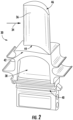
FIG. 2 illustrates a perspective view of a rotor blade, in accordance with embodiments of the present disclosure; -
FIG. 3 is a cross-sectional view, generally along a tangential direction, of a portion of a rotor blade, in accordance with embodiments of the present disclosure; -
FIG. 4 is a cross-sectional view, generally along an axial direction, of a portion of a rotor blade, in accordance with embodiments of the present disclosure; -
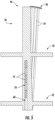
FIG. 5 is a cross-sectional view, generally along an axial direction, of a portion of a rotor blade, in accordance with other embodiments of the present disclosure; -
FIG. 6 is a cross-sectional view, generally along an axial direction, of a portion of a rotor blade, in accordance with still other embodiments of the present disclosure; -
FIG. 7 is a perspective view of a damper stack, in accordance with embodiments of the present disclosure; -
FIG. 8 is a cross-sectional view of a damper stack, in accordance with embodiments of the present disclosure; -
FIG. 9 is a cross-sectional view of a damper stack, in accordance with other embodiments of the present disclosure; and -
FIG. 10 is a cross-sectional view of a damper stack, in accordance with an embodiment of the disclosure that is not according to the invention and is present for illustration purposes only. - Reference now will be made in detail to embodiments of the present damper stacks, rotor blades, and turbomachines, one or more examples of which are illustrated in the drawings. Each example is provided by way of explanation, rather than limitation of, the technology. In fact, it will be apparent to those skilled in the art that modifications and variations can be made in the present technology without departing from the scope of the claimed technology. For instance, features illustrated or described as part of one embodiment can be used with another embodiment to yield a still further embodiment. Thus, it is intended that the present invention covers such modifications and variations as come within the scope of the appended claims.
- The detailed description uses numerical and letter designations to refer to features in the drawings. Like or similar designations in the drawings and description have been used to refer to like or similar parts of the invention. As used herein, the terms "first", "second", and "third" may be used interchangeably to distinguish one component from another and are not intended to signify location or importance of the individual components.
- Referring now to the drawings,
FIG. 1 illustrates a schematic diagram of one embodiment of a turbomachine, which in the illustrated embodiment is agas turbine 10. Although an industrial or land-based gas turbine is shown and described herein, the present disclosure is not limited to a land based and/or industrial gas turbine unless otherwise specified in the claims. For example, the invention as described herein may be used in any type of turbomachine including, but not limited to, a steam turbine, an aircraft gas turbine, or a marine gas turbine. - As shown,
gas turbine 10 generally includes aninlet section 12, acompressor section 14 disposed downstream of theinlet section 12, a plurality of combustors (not shown) within acombustor section 16 disposed downstream of thecompressor section 14, aturbine section 18 disposed downstream of thecombustor section 16, and anexhaust section 20 disposed downstream of theturbine section 18. Additionally, thegas turbine 10 may include one ormore shafts 22 coupled between thecompressor section 14 and theturbine section 18. - The
compressor section 14 may generally include a plurality of rotor disks 24 (one of which is shown) and a plurality ofrotor blades 26 extending radially outwardly from and connected to eachrotor disk 24. Eachrotor disk 24 in turn may be coupled to or form a portion of theshaft 22 that extends through thecompressor section 14. - The
turbine section 18 may generally include a plurality of rotor disks 28 (one of which is shown) and a plurality ofrotor blades 30 extending radially outwardly from and being interconnected to eachrotor disk 28. Eachrotor disk 28 in turn may be coupled to or form a portion of theshaft 22 that extends through theturbine section 18. Theturbine section 18 further includes anouter casing 31 that circumferentially surrounds the portion of theshaft 22 and therotor blades 30, thereby at least partially defining ahot gas path 32 through theturbine section 18. - During operation, a working fluid such as air flows through the
inlet section 12 and into thecompressor section 14 where the air is progressively compressed, thus providing pressurized air to the combustors of thecombustion section 16. The pressurized air is mixed with fuel and burned within each combustor to producecombustion gases 34. Thecombustion gases 34 flow through thehot gas path 32 from thecombustor section 16 into theturbine section 18, where energy (kinetic and/or thermal) is transferred from thecombustion gases 34 to therotor blades 30, causing theshaft 22 to rotate. The mechanical rotational energy may then be used to power thecompressor section 14 and/or to generate electricity. Thecombustion gases 34 exiting theturbine section 18 may then be exhausted from thegas turbine 10 via theexhaust section 20. -
FIG. 2 illustrates one embodiment of a rotor blade in accordance with embodiments of the present disclosure. In the embodiment shown, the rotor blade is a turbine blade orbucket 30, although, in alternative embodiments, the rotor blade could be a compressor blade orbucket 26. - The
rotor blade 30 includes a body which includes anairfoil 36 and ashank 38. Theairfoil 36 extends and is positioned radially outwardly from theshank 38. Theshank 38 may include a root ordovetail 40, which may attach to therotor disk 28 to facilitate rotation of therotor blade 30. - The
airfoil 36 may have a generally aerodynamic contour. For example, theairfoil 36 may have an exterior surface defining a pressure side and suction side each extending between a leading edge and a trailing edge. The exterior surface of theshank 38 may include a pressure side face, a suction side face, a leading edge face, and a trailing edge face. - A
platform 42 may generally surround the main body. A typical platform may be positioned at an intersection or transition between theairfoil 36 andshank 38 and extend outwardly in the generally axial and tangential directions, as shown. - Referring now to
FIGS. 3 and4 ,rotor blade 30 may further include one or more shrouds. For example, theairfoil 36 may extend radially between a base 44 (at the intersection between theairfoil 36 and shank 38) and atip 46. In some embodiments, atip shroud 50 may be provided at thetip 46 and may extend outwardly from theairfoil 36 in the generally axial and tangential directions. In some embodiments, one or more midspan shrouds 52 may be provided between thetip 46 and thebase 44 and may extend outwardly from theairfoil 36 in the generally axial and tangential directions. - One or
more cooling passages 54 may be defined in the main body, such as in theairfoil 36 as well as in theshank 38. Eachcooling passage 54 may extend radially through the main body, such as through the airfoil 36 (as shown) and/or theshank 38. Additionally, one ormore cooling passages 54 may be connected to form a cooling circuit.FIG. 3 illustrates afirst cooling circuit 56 and asecond cooling circuit 58, each of which includes a plurality ofconnected cooling passages 54. A cooling medium may be flowed through thecooling passages 54 to cool the main body androtor blade 30 during operation. - Referring now to
FIGS. 3 through 6 , one or more dampingpassages 60 are defined in and extend radially through the main body, such as in the airfoil 36 (as shown), as well as in theshank 38. In some embodiments, a dampingpassage 60 may be one of thecooling passages 54. In other embodiments, the dampingpassage 60 may be separate and independent from thecooling passages 54, such that cooling medium is not flowed through the dampingpassage 60. - Damping
passage 60 extends and is defined radially through the entire main body or only a portion thereof. For example, as discussed, at least a portion of (which may be the entire) dampingpassage 60 may extend and be defined through theairfoil 36. In some embodiments, as illustrated inFIG. 4 , the portion of the dampingpassage 60 extending and defined through theairfoil 36 may extend from the base 44 through thetip 46. In other embodiments, as illustrated inFIG. 5 , the dampingpassage 60 extends radially through only a portion of theairfoil 36 and does not extend to thetip 46. - In some embodiments, a
plug 62 may be provided and disposed within the dampingpassage 60 at thetip 46 or at another location in the dampingpassage 60. Theplug 62 may, for example, be brazed, welded, threadably engaged, or otherwise fastened in place at thetip 46 or at another location in the dampingpassage 60. In embodiments wherein the dampingpassage 60 extends through thetip 46, theplug 62 may be provided such that the dampingpassage 60 is not open externally to therotor blade 30. - In some embodiments, as illustrated in
FIGS. 4 and5 , the dampingpassage 60 is a single, unimpeded passageway. In other embodiments, as illustrated inFIG. 6 , the dampingpassage 60 may be segmented into one or more passage segments. This may allow for multiple independent damper stacks 70 (as discussed herein) to be utilized in a given dampingpassage 60. For example, astatic insert 64 may be disposed within the dampingpassage 60. Thestatic insert 64 may be provided in the dampingpassage 60 during casting or other formation of therotor blade 30 or may be inserted into the dampingpassage 60 after formation of therotor blade 30, such as by drilling anaccess hole 66 into therotor blade 30 and inserting thestatic insert 64 through theaccess hole 66 into the dampingpassage 60. In some embodiments, theaccess hole 66 may be formed at least partially through themidspan shroud 52. - Referring now to
FIGS. 3 through 10 , one or more damper stacks 70 is provided in arotor blade 30 in accordance with the present disclosure. Eachdamper stack 70 is disposed within a dampingpassage 60. Eachdamper stack 70 includes a plurality of damper pins 72. Eachdamper pin 72 is in contact with a neighboringdamper pin 72 in thedamper stack 70 and may further be in contact with walls defining the dampingpassage 60. - The use of damper stacks 70 in accordance with the present disclosure advantageously provides improved damping of
rotor blades 30 in accordance with the present disclosure. For example, by providing such damper stacks 70 internally inindividual rotor blades 30, the damper stacks 70 operate to dampen the absolute motion of theindividual rotor blades 30 regardless of the relative motion between neighboring blades. Such damper stacks 70 can, for example, advantageously dampen the absolute vibratory and/or bending motion ofindividual rotor blades 30. - Further, as discussed, damper stacks 70 in accordance with the present disclosure advantageously include a plurality of damper pins 72 arranged end-to-end in a co-axial relationship with a longitudinal axis of the damping
passage 60. The primary damping of damper stacks 70 is due to the contact between thepins 72 of thedamper stack 70. In addition, the damper pins 72 contact the sidewalls defining the dampingpassage 60, which also provides damping. - One or more damper stacks 70 is/are disposed within a damping
passage 60. In some embodiments, as illustrated inFIGS. 3 through 5 , only asingle damper stack 70 is disposed in a dampingpassage 60. In other embodiments, as illustrated inFIG. 6 , a plurality of damper stacks 70 may be disposed in a dampingpassage 60. In the embodiment illustrated inFIG. 6 , astatic insert 64 is disposed between neighboring damper stacks 70 of the plurality of damper stacks 70, thereby partitioning the neighboring damper stacks 70 into individual passage segments. - Referring now to
FIGS. 7 through 10 , various embodiments of damper stacks 70 in accordance with the present disclosure are illustrated. As discussed, adamper stack 70 includes a plurality of damper pins 72. Eachdamper pin 72 has alength 73, which is defined between afirst end 74 and asecond end 76 of thedamper pin 72. The damper pins 72 may be arranged in a length-wise linear array within a dampingpassage 60, such that the neighboring ends 74, 76 of neighboring damper pins 72 contact each other. - The plurality of damper pins 72 includes a first damper pin 72' and a
second damper pin 72", each of which extends between afirst end 74 and asecond end 76. Thefirst end 74 of the first damper pin 72' contacts thesecond end 76 of thesecond damper pin 72". In some embodiments, thesecond end 76 of the first damper pin 72' may contact another neighboringdamper pin 72, and/or thefirst end 74 of thesecond damper pin 72" may contact yet another neighboringdamper pin 72. - As discussed, the contact between neighboring damper pins 72 may provide the primary damping mechanism for damping of the
rotor blade 30. Centrifugal forces during operation cause the damper pins 72 to maintain such contact despite wearing. Accordingly, damper stacks 70 in accordance with the present disclosure advantageously continue to provide damping despite wearing during operation. - The ends 74, 76 of the neighboring damper pins 72 may have suitable shapes, which provide such primary damping. The neighboring ends 74, 76 of neighboring damper pins 72 have complementary spherical shapes. As illustrated in
FIGS. 8 and 9 , thefirst end 74 of the first damper pin 72' has an outward (i.e. convex) spherical shape, and thesecond end 76 of thesecond damper pin 72" has an inward (i.e. concave) spherical shape, or vice versa. In other embodiments of the disclosure that are not according to the invention and are present for illustration purposes only, other suitable complementary shapes, such as conical, domed, etc., which provide suitable damping, may be utilized. In other embodiments of the disclosure that are not according to the invention and are present for illustration purposes only, the neighboring ends 74, 76 of neighboring damper pins 72 may have mirrored shapes. For example, as illustrated inFIG. 10 , in an embodiment of the disclosure that is not according to the invention and is present for illustration purposes only, thefirst end 74 of the first damper pin 72' and thesecond end 76 of thesecond damper pin 72" may be flat surfaces that abut against each other. In embodiments of the disclosure that are not according to the invention and are present for illustration purposes only, othersuitable end - Damper pins 72 may, in some embodiments as illustrated, have generally oval or round cross-sectional profiles. Alternatively, other suitably-shaped cross-sectional profiles may be utilized. The cross-sectional profile may be constant or may vary along the
length 73 of thedamper pin 72. Further, damper pins 72 may have any suitable cross-sectional sizes. Still further, damper pins 72 may be formed from any suitable materials. The shapes, sizes, and/or materials may be identical for the plurality of damper pins 72 in adamper stack 70 or may vary for one or more of the damper pins 72 within adamper stack 70. - As discussed, each of the plurality of damper pins 72 may have a
length 73. In some embodiments, thelengths 73 of the damper pins 72 in adamper stack 70 may be identical. For example, as shown inFIGS. 8 and 10 , therespective lengths 73 of the first and second damper pins 72', 72" may be identical. In other embodiments, as shown inFIG. 9 , thelengths 73 of one or more damper pins 72 in adamper stack 70 may be different from other damper pins 72 in the stack. For example, as shown inFIG. 9 , thelength 73 of the first damper pin 72' may be different from thelength 73 of thesecond damper pin 72". - As discussed, in some embodiments, the damping
passage 60 is a cooling passage 54 (that is, a passage in fluid communication with a source of cooling medium, such as compressed air). Accordingly, in the illustrated embodiments, each of the plurality of damper pins 72 has a hollow cross-sectional profile, such that aninternal passage 78 is defined through the damper pins 72 anddamper stack 70. In these embodiments, cooling medium may flow through and/or around and past thedamper stack 70. It should be understood, however, that the use of damper pins 72 and damper stacks 70 having hollow cross-sectional profiles is not limited to embodiments in which the dampingpassage 60 is acooling passage 54. In other embodiments, such damper pins 72 and damper stacks 70 may be utilized in dampingpassages 60 that are separate and independent from thecooling passages 54. Further, in other embodiments, damper pins 72 and damper stacks 70 in accordance with the present disclosure may be solid, such that no internal passage is defined therethrough, and these solid damper pins 72 and damper stacks 70 may be utilized in dampingpassages 60 that are or are not coolingpassages 54. - In some embodiments, a wire (not shown) may extend through one or more or more damper pins 72 of the
damper stack 70. For example, the wire may extend through theinternal passages 78 or through separately defined internal passages, thus leavingpassages 78 empty. The wire may generally join the damper pins 72 together. In other embodiments, other suitable components may be utilized to join the damper pins 72 together, or the damper pins 72 may not be joined together. - This written description uses examples to disclose the invention, including the best mode, and also to enable any person skilled in the art to practice the invention, including making and using any devices or systems and performing any incorporated methods. The patentable scope of the invention is defined by the claims and may include other examples within the scope of the claims that occur to those skilled in the art.
Claims (10)
- A rotor blade (26, 30) for a turbomachine, the rotor blade (26, 30) comprising:a main body comprising a shank (38) and an airfoil (36) extending radially outwardly from the shank (38);a damping passage (60) defined in the main body, the damping passage (60) extending radially through the main body; anda damper stack (70) disposed within the damping passage (60), the damper stack (70) comprising a plurality of damper pins (72), each of the plurality of damper pins (72) in contact with a neighboring damper pin,wherein the plurality of damper pins (72) comprises a first damper pin (72') and a second damper pin (72"), wherein each of the plurality of damper pins (72) extends between a first end (74) and a second end (76), wherein the first end (74) of the first damper pin (72') contacts the second end (76) of the second damper pin (72"),characterized in that the first end (74) of the first damper pin (72') has an outward spherical shape and the second end (76) of the second damper pin (72") has an inward spherical shape.
- The rotor blade (26, 30) of claim 1, wherein a length (73) of each of the plurality of damper pins (72) is defined between the first end (74) and the second end (76) of the damper pin, and wherein the length (73) of the first damper pin (72') is different from the length (73) of the second damper pin (72").
- The rotor blade (26, 30) of any of claims 1-2, wherein each of the plurality of damper pins (72) has a hollow cross-sectional profile.
- The rotor blade (26, 30) of any of claims 1-3, wherein the damper stack (70) is a plurality of damper stacks (70), each of the plurality of damper stacks (70) disposed within the damping passage (60).
- The rotor blade (26, 30) of claim 4, further comprising a static insert (64) disposed within the damping passage (60) between neighboring damper stacks (70) of the plurality of damper stacks (70).
- The rotor blade (26, 30) of any of claims 1-5, wherein the damping passage (60) extends radially through only a portion of the airfoil (36).
- The rotor blade (26, 30) of any of claims 1-6, wherein the airfoil (36) extends radially between a base (44) and a tip (46), wherein the damping passage (60) is defined through the tip (46), and wherein a plug (62) is disposed within the damping passage (60) at the tip (46).
- A turbomachine, comprising:a compressor section (14);a combustor section (16);a turbine section (18); anda plurality of rotor blades (26, 30) provided in at least one of the compressor section (14) or the turbine section (18), each of the plurality of rotor blades (26, 30) comprising a rotor blade (26, 30) as claimed in any one of claims 1 to 9.
- The turbomachine of claim 10, wherein the plurality of rotor blades (30) are provided in a turbine section (18) of the turbomachine.
- The turbomachine of claim 10 or 11, wherein the turbomachine is a gas turbine (10).
Applications Claiming Priority (1)
| Application Number | Priority Date | Filing Date | Title |
|---|---|---|---|
| US16/708,999 US11187089B2 (en) | 2019-12-10 | 2019-12-10 | Damper stacks for turbomachine rotor blades |
Publications (2)
| Publication Number | Publication Date |
|---|---|
| EP3835548A1 EP3835548A1 (en) | 2021-06-16 |
| EP3835548B1 true EP3835548B1 (en) | 2023-05-10 |
Family
ID=73597845
Family Applications (1)
| Application Number | Title | Priority Date | Filing Date |
|---|---|---|---|
| EP20209646.7A Active EP3835548B1 (en) | 2019-12-10 | 2020-11-24 | Rotor blade for a turbomachine and turbomachine |
Country Status (4)
| Country | Link |
|---|---|
| US (1) | US11187089B2 (en) |
| EP (1) | EP3835548B1 (en) |
| JP (1) | JP7638676B2 (en) |
| CN (1) | CN112943376A (en) |
Families Citing this family (11)
| Publication number | Priority date | Publication date | Assignee | Title |
|---|---|---|---|---|
| US11519276B1 (en) | 2022-01-12 | 2022-12-06 | General Electric Company | Vibration damping system for turbine blade or nozzle, retention system therefor, and method of assembly |
| US11572791B1 (en) | 2022-01-12 | 2023-02-07 | General Electric Company | Vibration damping system for turbine nozzle or blade using damper pins with wire mesh members 1HEREON |
| US11634991B1 (en) | 2022-01-12 | 2023-04-25 | General Electric Company | Vibration damping system for turbine nozzle or blade using elongated body and wire mesh member |
| US11976565B2 (en) | 2022-07-27 | 2024-05-07 | Ge Infrastructure Technology Llc | Nested damper pin and vibration dampening system for turbine nozzle or blade |
| US12071862B2 (en) | 2022-07-27 | 2024-08-27 | Ge Infrastructure Technology Llc | Vibration damping system for turbine nozzle or blade using stacked plate members |
| US12371998B2 (en) * | 2023-06-29 | 2025-07-29 | Ge Infrastructure Technology Llc | Nested damper pin and vibration dampening system for turbine nozzle or blade |
| US12006831B1 (en) * | 2023-06-29 | 2024-06-11 | Ge Infrastructure Technology Llc | Damper element with spring-suspended bearing member for vibration dampening system for turbine blade |
| US12421856B2 (en) | 2023-06-29 | 2025-09-23 | Ge Infrastructure Technology Llc | Damper element with flexible legs for vibration dampening system for turbine blade |
| US12276205B2 (en) | 2023-06-29 | 2025-04-15 | Ge Infrastructure Technology Llc | Damper element with flexible legs for vibration dampening system for turbine blade |
| US12134972B1 (en) * | 2023-06-29 | 2024-11-05 | Ge Infrastructure Technology Llc | Damper element with spring-suspended bearing member for vibration dampening system for turbine blade |
| US12553349B2 (en) | 2023-06-29 | 2026-02-17 | Ge Infrastructure Technology Llc | Vibration dampening system including resonant-tuned elongated body for damper element(s) for turbine component |
Citations (1)
| Publication number | Priority date | Publication date | Assignee | Title |
|---|---|---|---|---|
| US20190017402A1 (en) * | 2016-01-12 | 2019-01-17 | Siemens Aktiengesellschaft | Flexible damper for turbine blades |
Family Cites Families (20)
| Publication number | Priority date | Publication date | Assignee | Title |
|---|---|---|---|---|
| FR981599A (en) | 1948-12-31 | 1951-05-28 | Vibration damping device | |
| US2999669A (en) | 1958-11-21 | 1961-09-12 | Westinghouse Electric Corp | Damping apparatus |
| US5820343A (en) * | 1995-07-31 | 1998-10-13 | United Technologies Corporation | Airfoil vibration damping device |
| US7121801B2 (en) * | 2004-02-13 | 2006-10-17 | United Technologies Corporation | Cooled rotor blade with vibration damping device |
| US7762780B2 (en) * | 2007-01-25 | 2010-07-27 | Siemens Energy, Inc. | Blade assembly in a combustion turbo-machine providing reduced concentration of mechanical stress and a seal between adjacent assemblies |
| US8267662B2 (en) | 2007-12-13 | 2012-09-18 | General Electric Company | Monolithic and bi-metallic turbine blade dampers and method of manufacture |
| US8066479B2 (en) * | 2010-04-05 | 2011-11-29 | Pratt & Whitney Rocketdyne, Inc. | Non-integral platform and damper for an airfoil |
| US8672626B2 (en) * | 2010-04-21 | 2014-03-18 | United Technologies Corporation | Engine assembled seal |
| US8876478B2 (en) * | 2010-11-17 | 2014-11-04 | General Electric Company | Turbine blade combined damper and sealing pin and related method |
| US9175570B2 (en) * | 2012-04-24 | 2015-11-03 | United Technologies Corporation | Airfoil including member connected by articulated joint |
| US9309782B2 (en) * | 2012-09-14 | 2016-04-12 | General Electric Company | Flat bottom damper pin for turbine blades |
| US9151165B2 (en) * | 2012-10-22 | 2015-10-06 | United Technologies Corporation | Reversible blade damper |
| JP5705810B2 (en) | 2012-10-26 | 2015-04-22 | 三菱重工業株式会社 | TOWER STRUCTURE AND CONSTRUCTION METHOD FOR TOWER STRUCTURE |
| US9194238B2 (en) * | 2012-11-28 | 2015-11-24 | General Electric Company | System for damping vibrations in a turbine |
| WO2014198277A1 (en) | 2013-06-11 | 2014-12-18 | Vestas Wind Systems A/S | Wind turbine tower having a damper |
| EP3091181A1 (en) | 2015-05-05 | 2016-11-09 | MTU Aero Engines GmbH | Blade for a turbomachine and corresponding manufacturing method |
| US10443408B2 (en) * | 2015-09-03 | 2019-10-15 | General Electric Company | Damper pin for a turbine blade |
| US10385701B2 (en) * | 2015-09-03 | 2019-08-20 | General Electric Company | Damper pin for a turbine blade |
| US20170067347A1 (en) * | 2015-09-03 | 2017-03-09 | General Electric Company | Slotted damper pin for a turbine blade |
| JP6802729B2 (en) | 2017-02-22 | 2020-12-16 | 三菱パワー株式会社 | Rotating machine wing damper device and rotating machine |
-
2019
- 2019-12-10 US US16/708,999 patent/US11187089B2/en active Active
-
2020
- 2020-11-24 JP JP2020194371A patent/JP7638676B2/en active Active
- 2020-11-24 EP EP20209646.7A patent/EP3835548B1/en active Active
- 2020-12-03 CN CN202011397049.7A patent/CN112943376A/en active Pending
Patent Citations (1)
| Publication number | Priority date | Publication date | Assignee | Title |
|---|---|---|---|---|
| US20190017402A1 (en) * | 2016-01-12 | 2019-01-17 | Siemens Aktiengesellschaft | Flexible damper for turbine blades |
Also Published As
| Publication number | Publication date |
|---|---|
| CN112943376A (en) | 2021-06-11 |
| JP7638676B2 (en) | 2025-03-04 |
| JP2021092222A (en) | 2021-06-17 |
| EP3835548A1 (en) | 2021-06-16 |
| US11187089B2 (en) | 2021-11-30 |
| US20210172325A1 (en) | 2021-06-10 |
Similar Documents
| Publication | Publication Date | Title |
|---|---|---|
| EP3835548B1 (en) | Rotor blade for a turbomachine and turbomachine | |
| EP3835550B1 (en) | Rotor blade for a turbomachine and turbomachine | |
| EP3139003B1 (en) | Damper pin for turbine blades and corresponding turbine engine | |
| CN106499442B (en) | Damper pin for turbine blade | |
| US20150204237A1 (en) | Turbine blade and method for enhancing life of the turbine blade | |
| EP3415719B1 (en) | Turbomachine blade cooling structure | |
| EP3978726B1 (en) | Vibrational dampening element and rotor blade | |
| US10156146B2 (en) | Airfoil with variable slot decoupling | |
| EP3885533B1 (en) | Rotor blade for a turbomachine and corresponding turbomachine | |
| CN106499444B (en) | Damper pins for turbine blades | |
| US20170191366A1 (en) | Slotted damper pin for a turbine blade | |
| US11767765B2 (en) | Glass viscous damper | |
| EP3978727B1 (en) | Rotor blade with damping structure | |
| JP2016037963A (en) | Turbine blade mid-span shroud assembly | |
| CN113464209B (en) | Turbine rotor blade with cooling circuit having offset ribs |
Legal Events
| Date | Code | Title | Description |
|---|---|---|---|
| PUAI | Public reference made under article 153(3) epc to a published international application that has entered the european phase |
Free format text: ORIGINAL CODE: 0009012 |
|
| STAA | Information on the status of an ep patent application or granted ep patent |
Free format text: STATUS: THE APPLICATION HAS BEEN PUBLISHED |
|
| AK | Designated contracting states |
Kind code of ref document: A1 Designated state(s): AL AT BE BG CH CY CZ DE DK EE ES FI FR GB GR HR HU IE IS IT LI LT LU LV MC MK MT NL NO PL PT RO RS SE SI SK SM TR |
|
| STAA | Information on the status of an ep patent application or granted ep patent |
Free format text: STATUS: REQUEST FOR EXAMINATION WAS MADE |
|
| 17P | Request for examination filed |
Effective date: 20211214 |
|
| RBV | Designated contracting states (corrected) |
Designated state(s): AL AT BE BG CH CY CZ DE DK EE ES FI FR GB GR HR HU IE IS IT LI LT LU LV MC MK MT NL NO PL PT RO RS SE SI SK SM TR |
|
| STAA | Information on the status of an ep patent application or granted ep patent |
Free format text: STATUS: EXAMINATION IS IN PROGRESS |
|
| 17Q | First examination report despatched |
Effective date: 20220602 |
|
| RIC1 | Information provided on ipc code assigned before grant |
Ipc: F01D 5/16 20060101AFI20221215BHEP |
|
| GRAP | Despatch of communication of intention to grant a patent |
Free format text: ORIGINAL CODE: EPIDOSNIGR1 |
|
| STAA | Information on the status of an ep patent application or granted ep patent |
Free format text: STATUS: GRANT OF PATENT IS INTENDED |
|
| INTG | Intention to grant announced |
Effective date: 20230127 |
|
| GRAS | Grant fee paid |
Free format text: ORIGINAL CODE: EPIDOSNIGR3 |
|
| GRAA | (expected) grant |
Free format text: ORIGINAL CODE: 0009210 |
|
| STAA | Information on the status of an ep patent application or granted ep patent |
Free format text: STATUS: THE PATENT HAS BEEN GRANTED |
|
| AK | Designated contracting states |
Kind code of ref document: B1 Designated state(s): AL AT BE BG CH CY CZ DE DK EE ES FI FR GB GR HR HU IE IS IT LI LT LU LV MC MK MT NL NO PL PT RO RS SE SI SK SM TR |
|
| REG | Reference to a national code |
Ref country code: GB Ref legal event code: FG4D |
|
| REG | Reference to a national code |
Ref country code: AT Ref legal event code: REF Ref document number: 1566860 Country of ref document: AT Kind code of ref document: T Effective date: 20230515 Ref country code: CH Ref legal event code: EP |
|
| REG | Reference to a national code |
Ref country code: DE Ref legal event code: R096 Ref document number: 602020010699 Country of ref document: DE |
|
| REG | Reference to a national code |
Ref country code: IE Ref legal event code: FG4D |
|
| REG | Reference to a national code |
Ref country code: LT Ref legal event code: MG9D |
|
| REG | Reference to a national code |
Ref country code: NL Ref legal event code: MP Effective date: 20230510 |
|
| REG | Reference to a national code |
Ref country code: AT Ref legal event code: MK05 Ref document number: 1566860 Country of ref document: AT Kind code of ref document: T Effective date: 20230510 |
|
| PG25 | Lapsed in a contracting state [announced via postgrant information from national office to epo] |
Ref country code: SE Free format text: LAPSE BECAUSE OF FAILURE TO SUBMIT A TRANSLATION OF THE DESCRIPTION OR TO PAY THE FEE WITHIN THE PRESCRIBED TIME-LIMIT Effective date: 20230510 Ref country code: PT Free format text: LAPSE BECAUSE OF FAILURE TO SUBMIT A TRANSLATION OF THE DESCRIPTION OR TO PAY THE FEE WITHIN THE PRESCRIBED TIME-LIMIT Effective date: 20230911 Ref country code: NO Free format text: LAPSE BECAUSE OF FAILURE TO SUBMIT A TRANSLATION OF THE DESCRIPTION OR TO PAY THE FEE WITHIN THE PRESCRIBED TIME-LIMIT Effective date: 20230810 Ref country code: NL Free format text: LAPSE BECAUSE OF FAILURE TO SUBMIT A TRANSLATION OF THE DESCRIPTION OR TO PAY THE FEE WITHIN THE PRESCRIBED TIME-LIMIT Effective date: 20230510 Ref country code: ES Free format text: LAPSE BECAUSE OF FAILURE TO SUBMIT A TRANSLATION OF THE DESCRIPTION OR TO PAY THE FEE WITHIN THE PRESCRIBED TIME-LIMIT Effective date: 20230510 Ref country code: AT Free format text: LAPSE BECAUSE OF FAILURE TO SUBMIT A TRANSLATION OF THE DESCRIPTION OR TO PAY THE FEE WITHIN THE PRESCRIBED TIME-LIMIT Effective date: 20230510 |
|
| REG | Reference to a national code |
Ref country code: DE Ref legal event code: R081 Ref document number: 602020010699 Country of ref document: DE Owner name: GENERAL ELECTRIC TECHNOLOGY GMBH, CH Free format text: FORMER OWNER: GENERAL ELECTRIC CO., SCHENECTADY, NY, US |
|
| PG25 | Lapsed in a contracting state [announced via postgrant information from national office to epo] |
Ref country code: RS Free format text: LAPSE BECAUSE OF FAILURE TO SUBMIT A TRANSLATION OF THE DESCRIPTION OR TO PAY THE FEE WITHIN THE PRESCRIBED TIME-LIMIT Effective date: 20230510 Ref country code: PL Free format text: LAPSE BECAUSE OF FAILURE TO SUBMIT A TRANSLATION OF THE DESCRIPTION OR TO PAY THE FEE WITHIN THE PRESCRIBED TIME-LIMIT Effective date: 20230510 Ref country code: LV Free format text: LAPSE BECAUSE OF FAILURE TO SUBMIT A TRANSLATION OF THE DESCRIPTION OR TO PAY THE FEE WITHIN THE PRESCRIBED TIME-LIMIT Effective date: 20230510 Ref country code: LT Free format text: LAPSE BECAUSE OF FAILURE TO SUBMIT A TRANSLATION OF THE DESCRIPTION OR TO PAY THE FEE WITHIN THE PRESCRIBED TIME-LIMIT Effective date: 20230510 Ref country code: IS Free format text: LAPSE BECAUSE OF FAILURE TO SUBMIT A TRANSLATION OF THE DESCRIPTION OR TO PAY THE FEE WITHIN THE PRESCRIBED TIME-LIMIT Effective date: 20230910 Ref country code: HR Free format text: LAPSE BECAUSE OF FAILURE TO SUBMIT A TRANSLATION OF THE DESCRIPTION OR TO PAY THE FEE WITHIN THE PRESCRIBED TIME-LIMIT Effective date: 20230510 Ref country code: GR Free format text: LAPSE BECAUSE OF FAILURE TO SUBMIT A TRANSLATION OF THE DESCRIPTION OR TO PAY THE FEE WITHIN THE PRESCRIBED TIME-LIMIT Effective date: 20230811 |
|
| RAP2 | Party data changed (patent owner data changed or rights of a patent transferred) |
Owner name: GENERAL ELECTRIC TECHNOLOGY GMBH |
|
| PG25 | Lapsed in a contracting state [announced via postgrant information from national office to epo] |
Ref country code: FI Free format text: LAPSE BECAUSE OF FAILURE TO SUBMIT A TRANSLATION OF THE DESCRIPTION OR TO PAY THE FEE WITHIN THE PRESCRIBED TIME-LIMIT Effective date: 20230510 |
|
| PG25 | Lapsed in a contracting state [announced via postgrant information from national office to epo] |
Ref country code: SK Free format text: LAPSE BECAUSE OF FAILURE TO SUBMIT A TRANSLATION OF THE DESCRIPTION OR TO PAY THE FEE WITHIN THE PRESCRIBED TIME-LIMIT Effective date: 20230510 |
|
| PG25 | Lapsed in a contracting state [announced via postgrant information from national office to epo] |
Ref country code: SM Free format text: LAPSE BECAUSE OF FAILURE TO SUBMIT A TRANSLATION OF THE DESCRIPTION OR TO PAY THE FEE WITHIN THE PRESCRIBED TIME-LIMIT Effective date: 20230510 Ref country code: SK Free format text: LAPSE BECAUSE OF FAILURE TO SUBMIT A TRANSLATION OF THE DESCRIPTION OR TO PAY THE FEE WITHIN THE PRESCRIBED TIME-LIMIT Effective date: 20230510 Ref country code: RO Free format text: LAPSE BECAUSE OF FAILURE TO SUBMIT A TRANSLATION OF THE DESCRIPTION OR TO PAY THE FEE WITHIN THE PRESCRIBED TIME-LIMIT Effective date: 20230510 Ref country code: EE Free format text: LAPSE BECAUSE OF FAILURE TO SUBMIT A TRANSLATION OF THE DESCRIPTION OR TO PAY THE FEE WITHIN THE PRESCRIBED TIME-LIMIT Effective date: 20230510 Ref country code: DK Free format text: LAPSE BECAUSE OF FAILURE TO SUBMIT A TRANSLATION OF THE DESCRIPTION OR TO PAY THE FEE WITHIN THE PRESCRIBED TIME-LIMIT Effective date: 20230510 Ref country code: CZ Free format text: LAPSE BECAUSE OF FAILURE TO SUBMIT A TRANSLATION OF THE DESCRIPTION OR TO PAY THE FEE WITHIN THE PRESCRIBED TIME-LIMIT Effective date: 20230510 |
|
| REG | Reference to a national code |
Ref country code: DE Ref legal event code: R097 Ref document number: 602020010699 Country of ref document: DE |
|
| PLBE | No opposition filed within time limit |
Free format text: ORIGINAL CODE: 0009261 |
|
| STAA | Information on the status of an ep patent application or granted ep patent |
Free format text: STATUS: NO OPPOSITION FILED WITHIN TIME LIMIT |
|
| 26N | No opposition filed |
Effective date: 20240213 |
|
| PG25 | Lapsed in a contracting state [announced via postgrant information from national office to epo] |
Ref country code: SI Free format text: LAPSE BECAUSE OF FAILURE TO SUBMIT A TRANSLATION OF THE DESCRIPTION OR TO PAY THE FEE WITHIN THE PRESCRIBED TIME-LIMIT Effective date: 20230510 |
|
| PG25 | Lapsed in a contracting state [announced via postgrant information from national office to epo] |
Ref country code: SI Free format text: LAPSE BECAUSE OF FAILURE TO SUBMIT A TRANSLATION OF THE DESCRIPTION OR TO PAY THE FEE WITHIN THE PRESCRIBED TIME-LIMIT Effective date: 20230510 |
|
| REG | Reference to a national code |
Ref country code: CH Ref legal event code: PL |
|
| PG25 | Lapsed in a contracting state [announced via postgrant information from national office to epo] |
Ref country code: MC Free format text: LAPSE BECAUSE OF FAILURE TO SUBMIT A TRANSLATION OF THE DESCRIPTION OR TO PAY THE FEE WITHIN THE PRESCRIBED TIME-LIMIT Effective date: 20230510 |
|
| PG25 | Lapsed in a contracting state [announced via postgrant information from national office to epo] |
Ref country code: LU Free format text: LAPSE BECAUSE OF NON-PAYMENT OF DUE FEES Effective date: 20231124 |
|
| PG25 | Lapsed in a contracting state [announced via postgrant information from national office to epo] |
Ref country code: CH Free format text: LAPSE BECAUSE OF NON-PAYMENT OF DUE FEES Effective date: 20231130 |
|
| PG25 | Lapsed in a contracting state [announced via postgrant information from national office to epo] |
Ref country code: MC Free format text: LAPSE BECAUSE OF FAILURE TO SUBMIT A TRANSLATION OF THE DESCRIPTION OR TO PAY THE FEE WITHIN THE PRESCRIBED TIME-LIMIT Effective date: 20230510 Ref country code: LU Free format text: LAPSE BECAUSE OF NON-PAYMENT OF DUE FEES Effective date: 20231124 Ref country code: CH Free format text: LAPSE BECAUSE OF NON-PAYMENT OF DUE FEES Effective date: 20231130 |
|
| REG | Reference to a national code |
Ref country code: BE Ref legal event code: MM Effective date: 20231130 |
|
| REG | Reference to a national code |
Ref country code: IE Ref legal event code: MM4A |
|
| PG25 | Lapsed in a contracting state [announced via postgrant information from national office to epo] |
Ref country code: IE Free format text: LAPSE BECAUSE OF NON-PAYMENT OF DUE FEES Effective date: 20231124 |
|
| PG25 | Lapsed in a contracting state [announced via postgrant information from national office to epo] |
Ref country code: BE Free format text: LAPSE BECAUSE OF NON-PAYMENT OF DUE FEES Effective date: 20231130 |
|
| PG25 | Lapsed in a contracting state [announced via postgrant information from national office to epo] |
Ref country code: FR Free format text: LAPSE BECAUSE OF NON-PAYMENT OF DUE FEES Effective date: 20231130 |
|
| PG25 | Lapsed in a contracting state [announced via postgrant information from national office to epo] |
Ref country code: IE Free format text: LAPSE BECAUSE OF NON-PAYMENT OF DUE FEES Effective date: 20231124 Ref country code: FR Free format text: LAPSE BECAUSE OF NON-PAYMENT OF DUE FEES Effective date: 20231130 Ref country code: BE Free format text: LAPSE BECAUSE OF NON-PAYMENT OF DUE FEES Effective date: 20231130 |
|
| PG25 | Lapsed in a contracting state [announced via postgrant information from national office to epo] |
Ref country code: BG Free format text: LAPSE BECAUSE OF FAILURE TO SUBMIT A TRANSLATION OF THE DESCRIPTION OR TO PAY THE FEE WITHIN THE PRESCRIBED TIME-LIMIT Effective date: 20230510 |
|
| PG25 | Lapsed in a contracting state [announced via postgrant information from national office to epo] |
Ref country code: BG Free format text: LAPSE BECAUSE OF FAILURE TO SUBMIT A TRANSLATION OF THE DESCRIPTION OR TO PAY THE FEE WITHIN THE PRESCRIBED TIME-LIMIT Effective date: 20230510 |
|
| GBPC | Gb: european patent ceased through non-payment of renewal fee |
Effective date: 20241124 |
|
| PG25 | Lapsed in a contracting state [announced via postgrant information from national office to epo] |
Ref country code: CY Free format text: LAPSE BECAUSE OF FAILURE TO SUBMIT A TRANSLATION OF THE DESCRIPTION OR TO PAY THE FEE WITHIN THE PRESCRIBED TIME-LIMIT; INVALID AB INITIO Effective date: 20201124 |
|
| PG25 | Lapsed in a contracting state [announced via postgrant information from national office to epo] |
Ref country code: HU Free format text: LAPSE BECAUSE OF FAILURE TO SUBMIT A TRANSLATION OF THE DESCRIPTION OR TO PAY THE FEE WITHIN THE PRESCRIBED TIME-LIMIT; INVALID AB INITIO Effective date: 20201124 |
|
| PG25 | Lapsed in a contracting state [announced via postgrant information from national office to epo] |
Ref country code: GB Free format text: LAPSE BECAUSE OF NON-PAYMENT OF DUE FEES Effective date: 20241124 |
|
| PG25 | Lapsed in a contracting state [announced via postgrant information from national office to epo] |
Ref country code: TR Free format text: LAPSE BECAUSE OF FAILURE TO SUBMIT A TRANSLATION OF THE DESCRIPTION OR TO PAY THE FEE WITHIN THE PRESCRIBED TIME-LIMIT Effective date: 20230510 |
|
| PGFP | Annual fee paid to national office [announced via postgrant information from national office to epo] |
Ref country code: DE Payment date: 20251022 Year of fee payment: 6 |
|
| PGFP | Annual fee paid to national office [announced via postgrant information from national office to epo] |
Ref country code: IT Payment date: 20251022 Year of fee payment: 6 |