EP3835476A1 - Clothes drying systems having control based on surrounding temperature detection - Google Patents
Clothes drying systems having control based on surrounding temperature detection Download PDFInfo
- Publication number
- EP3835476A1 EP3835476A1 EP19214695.9A EP19214695A EP3835476A1 EP 3835476 A1 EP3835476 A1 EP 3835476A1 EP 19214695 A EP19214695 A EP 19214695A EP 3835476 A1 EP3835476 A1 EP 3835476A1
- Authority
- EP
- European Patent Office
- Prior art keywords
- air
- temperature
- control valve
- drum
- signal
- Prior art date
- Legal status (The legal status is an assumption and is not a legal conclusion. Google has not performed a legal analysis and makes no representation as to the accuracy of the status listed.)
- Granted
Links
Images

Classifications
-
- D—TEXTILES; PAPER
- D06—TREATMENT OF TEXTILES OR THE LIKE; LAUNDERING; FLEXIBLE MATERIALS NOT OTHERWISE PROVIDED FOR
- D06F—LAUNDERING, DRYING, IRONING, PRESSING OR FOLDING TEXTILE ARTICLES
- D06F33/00—Control of operations performed in washing machines or washer-dryers
- D06F33/50—Control of washer-dryers characterised by the purpose or target of the control
- D06F33/52—Control of the operational steps, e.g. optimisation or improvement of operational steps depending on the condition of the laundry
- D06F33/63—Control of the operational steps, e.g. optimisation or improvement of operational steps depending on the condition of the laundry of air flow, e.g. blowing air during the washing process to prevent entanglement of the laundry
-
- D—TEXTILES; PAPER
- D06—TREATMENT OF TEXTILES OR THE LIKE; LAUNDERING; FLEXIBLE MATERIALS NOT OTHERWISE PROVIDED FOR
- D06F—LAUNDERING, DRYING, IRONING, PRESSING OR FOLDING TEXTILE ARTICLES
- D06F34/00—Details of control systems for washing machines, washer-dryers or laundry dryers
- D06F34/14—Arrangements for detecting or measuring specific parameters
-
- D—TEXTILES; PAPER
- D06—TREATMENT OF TEXTILES OR THE LIKE; LAUNDERING; FLEXIBLE MATERIALS NOT OTHERWISE PROVIDED FOR
- D06F—LAUNDERING, DRYING, IRONING, PRESSING OR FOLDING TEXTILE ARTICLES
- D06F2101/00—User input for the control of domestic laundry washing machines, washer-dryers or laundry dryers
- D06F2101/18—Target temperature for the drying process, e.g. low-temperature cycles
-
- D—TEXTILES; PAPER
- D06—TREATMENT OF TEXTILES OR THE LIKE; LAUNDERING; FLEXIBLE MATERIALS NOT OTHERWISE PROVIDED FOR
- D06F—LAUNDERING, DRYING, IRONING, PRESSING OR FOLDING TEXTILE ARTICLES
- D06F2103/00—Parameters monitored or detected for the control of domestic laundry washing machines, washer-dryers or laundry dryers
-
- D—TEXTILES; PAPER
- D06—TREATMENT OF TEXTILES OR THE LIKE; LAUNDERING; FLEXIBLE MATERIALS NOT OTHERWISE PROVIDED FOR
- D06F—LAUNDERING, DRYING, IRONING, PRESSING OR FOLDING TEXTILE ARTICLES
- D06F2103/00—Parameters monitored or detected for the control of domestic laundry washing machines, washer-dryers or laundry dryers
- D06F2103/28—Air properties
- D06F2103/32—Temperature
-
- D—TEXTILES; PAPER
- D06—TREATMENT OF TEXTILES OR THE LIKE; LAUNDERING; FLEXIBLE MATERIALS NOT OTHERWISE PROVIDED FOR
- D06F—LAUNDERING, DRYING, IRONING, PRESSING OR FOLDING TEXTILE ARTICLES
- D06F2105/00—Systems or parameters controlled or affected by the control systems of washing machines, washer-dryers or laundry dryers
- D06F2105/16—Air properties
- D06F2105/20—Temperature
-
- D—TEXTILES; PAPER
- D06—TREATMENT OF TEXTILES OR THE LIKE; LAUNDERING; FLEXIBLE MATERIALS NOT OTHERWISE PROVIDED FOR
- D06F—LAUNDERING, DRYING, IRONING, PRESSING OR FOLDING TEXTILE ARTICLES
- D06F2105/00—Systems or parameters controlled or affected by the control systems of washing machines, washer-dryers or laundry dryers
- D06F2105/28—Electric heating
-
- D—TEXTILES; PAPER
- D06—TREATMENT OF TEXTILES OR THE LIKE; LAUNDERING; FLEXIBLE MATERIALS NOT OTHERWISE PROVIDED FOR
- D06F—LAUNDERING, DRYING, IRONING, PRESSING OR FOLDING TEXTILE ARTICLES
- D06F2105/00—Systems or parameters controlled or affected by the control systems of washing machines, washer-dryers or laundry dryers
- D06F2105/30—Blowers
-
- D—TEXTILES; PAPER
- D06—TREATMENT OF TEXTILES OR THE LIKE; LAUNDERING; FLEXIBLE MATERIALS NOT OTHERWISE PROVIDED FOR
- D06F—LAUNDERING, DRYING, IRONING, PRESSING OR FOLDING TEXTILE ARTICLES
- D06F2105/00—Systems or parameters controlled or affected by the control systems of washing machines, washer-dryers or laundry dryers
- D06F2105/32—Air flow control means
-
- D—TEXTILES; PAPER
- D06—TREATMENT OF TEXTILES OR THE LIKE; LAUNDERING; FLEXIBLE MATERIALS NOT OTHERWISE PROVIDED FOR
- D06F—LAUNDERING, DRYING, IRONING, PRESSING OR FOLDING TEXTILE ARTICLES
- D06F25/00—Washing machines with receptacles, e.g. perforated, having a rotary movement, e.g. oscillatory movement, the receptacle serving both for washing and for centrifugally separating water from the laundry and having further drying means, e.g. using hot air
-
- D—TEXTILES; PAPER
- D06—TREATMENT OF TEXTILES OR THE LIKE; LAUNDERING; FLEXIBLE MATERIALS NOT OTHERWISE PROVIDED FOR
- D06F—LAUNDERING, DRYING, IRONING, PRESSING OR FOLDING TEXTILE ARTICLES
- D06F58/00—Domestic laundry dryers
- D06F58/20—General details of domestic laundry dryers
- D06F58/24—Condensing arrangements
-
- D—TEXTILES; PAPER
- D06—TREATMENT OF TEXTILES OR THE LIKE; LAUNDERING; FLEXIBLE MATERIALS NOT OTHERWISE PROVIDED FOR
- D06F—LAUNDERING, DRYING, IRONING, PRESSING OR FOLDING TEXTILE ARTICLES
- D06F58/00—Domestic laundry dryers
- D06F58/32—Control of operations performed in domestic laundry dryers
- D06F58/34—Control of operations performed in domestic laundry dryers characterised by the purpose or target of the control
- D06F58/36—Control of operational steps, e.g. for optimisation or improvement of operational steps depending on the condition of the laundry
- D06F58/38—Control of operational steps, e.g. for optimisation or improvement of operational steps depending on the condition of the laundry of drying, e.g. to achieve the target humidity
Definitions
- the present application relates to clothes drying systems and, in particular, clothes drying systems that control operations based on surrounding temperatures.
- Combination washing and drying apparatuses include both a washing cycle for washing clothes and a drying cycle for drying clothes.
- the washing and drying apparatuses may be either open-loop (vented) or closed-loop (condensing).
- an open-loop washing and drying apparatus the wet air from a drum where the clothes are dried is directed to the environment.
- a closed-loop washing and drying apparatus the wet air from the drum is directed to a condenser where moisture is removed from the wet air. The drier air is then directed from the condenser back to the drum for the drying operation.
- open and closed-loop drying systems have advantages. For example, open-loop drying systems vent the wet air to the environment and replace the vented air with drier intake air. This venting of the relatively wet air can reduce drying time compared to a closed-loop drying system. Closed-loop drying systems may be used in locations where a vent is not present or would require major infrastructure changes to allow access to an outside space, such as in some apartment buildings. These closed-loop drying systems can have longer drying times than open-loop drying systems. It would be desirable to allow some controlled venting into a room to relatively quickly remove moist air from the system, which can reduce drying time compared to a closed-loop drying system.
- a clothes drying system includes an apparatus that comprises a drying air circuit.
- the system includes a drum in communication with the drying air circuit.
- a condenser is in communication with the drying air circuit and is located downstream of the drum.
- the condenser includes a cooled water inlet that directs cooled water into the heated air to remove moisture from the heated air.
- the condenser includes a condenser water outlet for egress of water from the condenser.
- the cooled water inlet of the condenser is configured to receive water from a tap water source.
- a temperature sensor provides a signal indicative of a temperature of an environment outside the apparatus. The temperature sensor may be part of the apparatus or may be removed from the apparatus and communicate wirelessly with the apparatus.
- a memory and processing circuitry is coupled to the memory.
- the memory includes logic that, when executed by the processing circuitry, directs at least one of: (i) a vent air control valve to change an amount of heated air flowing from the drum through the vent air control valve and into the environment based on the signal from the temperature sensor, (ii) a fan to change a flow rate of air flowing through the drying air circuit based on the signal from the temperature sensor, and (iii) a heater to change an amount of heat provided to the air flowing through the drying air circuit based on the signal from the temperature sensor.
- a vent air control valve to change an amount of heated air flowing from the drum through the vent air control valve and into the environment based on the signal from the temperature sensor
- a fan to change a flow rate of air flowing through the drying air circuit based on the signal from the temperature sensor
- a heater to change an amount of heat provided to the air flowing through the drying air circuit based on the signal from the temperature sensor.
- a method of controlling a clothes drying system comprising an apparatus that comprises a drying air circuit.
- the method includes directing air through the drying air circuit to a drum. Heated air is directed from the drum to a condenser in communication with the drying air circuit and located downstream of the drum.
- the condenser includes a cooled water inlet directing cooled water into the heated air thereby removing moisture from the heated air, the cooled water inlet of the condenser configured to receive water from a tap water source.
- a signal is provided using a temperature sensor indicative of a temperature of an environment outside the apparatus.
- a controller Based on the signal from the temperature sensor, a controller directs at least one of: (i) a vent air control valve to change an amount of heated air flowing from the drum through the vent air control valve and into the environment based on the signal from the temperature sensor, (ii) a fan to change a flow rate of air flowing through the drying air circuit based on the signal from the temperature sensor, and (iii) a heater to change an amount of heat provided to the air flowing through the drying air circuit based on the signal from the temperature sensor.
- Embodiments described herein are generally directed to a drying apparatuses that include a drying air circuit for use during a drying cycle.
- the drying apparatuses may also include a wash water circuit for use in a washing cycle.
- the drying apparatuses include a drum that is in communication with both the drying air circuit and the wash water circuit.
- a condenser is in communication with the closed drying air circuit and is located downstream of the drum for receiving heated wet air (i.e., high humidity) from the drum during the drying cycle.
- the condenser has a water inlet that directs water into the heated air for removing moisture from the heated wet air through the process of condensation.
- the drying apparatuses further include a temperature sensor that provides a signal that is indicative of a temperature of an environment outside the drying apparatuses.
- the temperature sensor may be part of the apparatus or may be removed from the apparatus and communicate wirelessly with the apparatus.
- the drying apparatuses include a memory and processing circuitry coupled to the memory.
- the memory includes logic that, when executed by the processing circuitry, directs at least one of (i) an air control valve (i.e., a vent valve) to change an amount of heated, wet air that exits the drum to travel through the air control valve and into the environment based on the signal from the temperature sensor, (ii) a fan to change a flow rate of air flowing through the drying air circuit based on the signal from the temperature sensor, and (iii) a heater to change an amount of heat provided to the air flowing through the drying air circuit based on the signal from the temperature sensor.
- an air control valve i.e., a vent valve
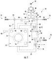
- a washing and drying apparatus 10 is illustrated diagrammatically and includes a housing 12, a tub 14 located in the housing and a drum 16 that is located inside the tub 14.
- a motor 19 is located inside the housing 12 and is used to rotate the drum 16.
- the washing and drying apparatus 10 includes a closed drying air circuit, generally referenced as element 18, and a wash water circuit, generally referenced as element 20. While components of the closed drying air circuit 18 and the wash water circuit 20 are illustrated outside the housing 12, this is merely for illustration as the closed drying air circuit 18 and wash water circuit 20 are located inside the housing 12.
- the closed drying air circuit 18 includes an air circulation duct 22 that is fluidly connected to the drum 16.
- the air circulation duct 22 is fluidly connected to the drum 16 for delivering air that is heated by heater 24 to a heated temperature to the drum 16 during a drying cycle.
- a fan 27 may be provided to encourage air circulation through the air circulation duct 22 to and from the drum 16.
- the closed drying air circuit 18 further includes a vent air control valve 28 that is located upstream from a condenser 30 and between the condenser 30 and the drum 16 and an intake air control valve 32 that is located downstream of the condenser 30 and between the condenser 30 and the fan 27.
- the heated wet air may be delivered through the circulation duct 22 to an air inlet 34 of the condenser 30.
- the condenser 30 includes a condensing apparatus 36 (e.g., a tube, etc.) that is fluidly connected to the circulation duct 22 at both the air inlet 34 and an air outlet 38.
- the condenser 30 is configured to remove moisture from the heated wet air and through the process of condensation before the air is reheated by heater 24 and delivered back to the drum 16 with reduced relative humidity after heating back to about the same (e.g., ⁇ 5 °C) heated temperature.
- the vent air control valve 28 allows the heated air to be vented from the circulation duct 22 to the surrounding environment.
- a filter 33 may be provided for filtering the air as it is being vented.
- the vent air control valve 28 may be controllable to allow venting of between zero percent and 100 percent. The percentage or fraction of total air flow being vented at the vent air control valve 28 may be referred to as the "vented fraction.”
- the vent air control valve 28 is used to change the vented fraction, as will be described in greater detail below.
- the intake air control valve 32 allows drier outside air to enter the circulation duct 22. The amount of air entering the circulation duct 22 through the intake air control valve 32 may be controlled to be substantially the same amount of air exiting the circulation duct 22 through the vent air control valve 28 in order to maintain a desired pressure within the circulation duct 22.
- thermoelectric apparatus 40 includes a thermoelectric device 56 that may be provided between the condenser 30 and a tap water source 42.
- a "thermoelectric device” refers to a device that uses the Peltier effect to create a heat flux at the junction of two different types of materials.
- the thermoelectric device is a solid-state active heat pump that transfers heat from one side of the device to the other using electrical energy.
- the thermoelectric apparatus 40 includes a hot side flow device 44 that includes a hot side water input 46 and a hot side water output 48.
- the thermoelectric apparatus 40 further includes a cold side flow device 50 that includes a cold side water input 52 and a cold side water output 54.
- the hot side flow device 44 and the cold side flow device 50 each contain a duct that extends between the inputs 46, 52 and outputs 48, 54 that can be any suitable shape, such as curved, undulating, straight, etc. that allows for heating and cooling of the tap water therethrough.
- Located between the hot side flow device 44 and the cold side flow device 50 is the thermoelectric device 56.
- the thermoelectric device 56 may be connected to the hot side flow device 44 and the cold side flow device 50 using any suitable process, such as a thermal adhesive.
- the thermoelectric device 56 transfers heat from tap water flow through the cold side flow device 50 to tap water flowing through the hot side flow device 44 thereby cooling the tap water from an initial tap outlet temperature to a cooled water temperature.
- thermoelectric device any other suitable device (e.g., refrigerant-based, water-based, etc.) may be used to cool the incoming tap water or, in some embodiments, a device to cool the incoming tap water may not be used.
- any other suitable device e.g., refrigerant-based, water-based, etc.
- refrigerant-based, water-based, etc. may be used to cool the incoming tap water or, in some embodiments, a device to cool the incoming tap water may not be used.
- the cooled water is delivered along line 58 to the condenser 30.
- the cooled water 60 is released into the condenser 30 at a rate of between about 1 g/s and about 16 g/s.
- the cooled water 60 is released from a cooled water inlet 64 along an inner surface of a wall of the condenser 30, which cools the wall to a temperature below that of the heated wet air 70 entering the condenser.
- the cooled water inlet 64 may include a nozzle 72 having a reduced inner diameter compared to the line 58 to generate a spray of small cooled water droplets.
- the droplet size may be large enough that the water droplets do not become entrained in the heated wet air 70 and to increase the heat transfer coefficient and/or the heat transfer area of the cooled water droplets.
- a droplet size of greater than about 1076 ⁇ m from the nozzle 72 may be used.
- a pump upstream of the nozzle may be used to generate adequate hydraulic pressure necessary for atomization of the water.
- Water that is removed from the air and also provided to the condenser 30 through the line 58 is directed to a drain, represented by element 74.
- a pump 76 may be provided at a condenser water outlet 78 to pump the water from the condenser 30.
- the washing and drying apparatus 10 may include a controller 80.
- the controller 80 may include processing circuitry and a memory that includes logic in the form of machine-readable instructions that is used to control operation of the one or more valves and pumps during the washing and drying cycles.
- the logic may cause the processing circuitry to direct cooled water from the cold side flow device 50 to the drain 74 using valve 82 (e.g., a 3-way valve) that is communicatively coupled to the controller 80.
- the heated water from the hot side flow device 44 may be directed to the tub 14 using valve 84 and pump 86 that are communicatively coupled to the controller 80.
- the logic may cause the processing circuitry to direct heated water from the hot side flow device 44 to the drain 74 using valve 84.
- the cooled water from the cold side flow device 50 may be directed to the condenser 30 using the valve 82.
- the controller 80 may control the fan 27, the vent air control valve 28 and/or the intake air control valve 32 to maintain a preselected air flow rate through the condenser 30.
- a temperature sensor 90 may provide a signal that is indicative of a temperature of an environment outside the washing and drying apparatus 10.
- the controller 80 may include the memory that may include logic that, when executed by the processing circuitry, directs at least one of the (i) vent air control valve 28 to change an amount of heated, wet air that exits the drum 16 to travel through the vent air control valve 28 and into the environment based on the signal from the temperature sensor 90, (ii) fan 27 to change a flow rate of air flowing through the circulation duct 22 based on the signal from the temperature sensor, and (iii) heater 24 to change an amount of heat provided to the air flowing through the circulation duct 22 based on the signal from the temperature sensor.
- thermosensor 90 Other sensor types may also be used in conjunction with the temperature sensor 90, such as a humidity sensor that provides a signal indicative of a humidity level of the environment outside the washing and drying apparatus 10 and/or a proximity sensor that can provide spatial information, such as dimensions of a room in which the washing and drying apparatus 10 is located.
- a humidity sensor that provides a signal indicative of a humidity level of the environment outside the washing and drying apparatus 10
- a proximity sensor that can provide spatial information, such as dimensions of a room in which the washing and drying apparatus 10 is located.
- the memory may include a default temperature (e.g., between about 20 °C and 25 °C) that is used by the controller 80 to control operation of the washing and drying apparatus 10 based on a difference between the default temperature and a surrounding temperature determined based on the signal from the temperature sensor 90. Details of the control based on temperature difference will be described in greater detail below.
- a user input 94 may be provided that allows a user to input a user selected temperature that is different from (i.e., higher or lower) the default temperature.
- the controller 80 may control operation of the washing and drying apparatus 10 based on a difference between the user selected temperature and the surrounding temperature determined based on the signal from the temperature sensor 90.
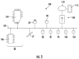
- the washing and drying system 100 includes a communication path 102, the controller 80 including a processor 104, a memory module 106, the fan 27, the heater 24, the vent air control valve 28, the intake air control valve 32, the sensor 90 (temperature, proximity and humidity) and the user input 94.
- the processor 104 may include any device capable of executing machine-readable instructions stored on a non-transitory computer-readable medium.
- the processor 104 may include one or more processors. Accordingly, each processor 104 may include a controller, an integrated circuit, a microchip, a computer, and/or any other computing device.
- the washing and drying system 100 may further include network interface hardware 108.
- the communication path 102 can provide data interconnectivity between the various modules that may send and receive data.
- the communication path 102 may be wired and/or wireless.
- the washing and drying system 100 may further include the network interface hardware 108 for communicatively coupling the washing and drying system 100 with a network 110.
- the network interface hardware 108 can be communicatively coupled to the communication path 102 and can be any device capable to transmitting and receiving data via the network 113.
- the network interface hardware 108 may include antenna, modem, LAN port, Wi-Fi, mobile communications hardware, etc.
- the network interface hardware 108 may include a Bluetooth® module for sending and receiving Bluetooth communications to and from a mobile device 114.
- the network interface hardware 108 can allow to control operation of the washing and drying system 100 and to input the user selected temperature remotely, for example, using a handheld computing device 113.
- a method 120 of controlling the washing and drying system 100 includes the temperature sensor 90 sending a signal to the controller 80 that is indicative of temperature of the environment around the washing and drying apparatus 10 at step 122.
- the controller 80 checks for a user selected temperature. If a user selected temperature is present, the controller 80 determines if the surrounding temperature is greater than the user selected temperature at step 126.
- the controller 80 may reduce one or more of (i) the vented fraction using the vent air control valve 28, which reduces the amount of wet, heated air vented into the surroundings as step 128, (ii) the heat from the heater 24, which reduces the air temperature in the circulation duct 22 at step 130, and (iii) the air flow rate using the fan 27, which also reduces the amount of wet, heated air vented at step 132.
- the controller 80 may increase one or more of (i) the vented fraction using the vent air control valve 28, which increases the amount of wet, heated air vented into the surroundings as step 134, (ii) the heat from the heater 24, which increases the air temperature in the circulation duct 22 at step 136, and (iii) the air flow rate using the fan 27, which also increases the amount of wet, heated air vented at step 138.
- Increasing one or more of the vented fraction, air temperature and air flow rate can reduce drying time of clothes in the drum, taking advantage of the reduced temperature of the surroundings.
- the amount of change of the vented fraction, air temperature and air flow rate can be determined by an algorithm to reduce the absolute value of the difference between the user selected temperature and the surrounding temperature.
- the controller determines if the surrounding temperature is greater than the default temperature at step 140. If the surrounding temperature is greater than the default temperature, the controller 80 may reduce one or more of (i) the vented fraction using the vent air control valve 28, which reduces the amount of wet, heated air vented into the surroundings at step 142, (ii) the heat from the heater 24, which reduces the air temperature in the circulation duct 22 at step 144, and (iii) the air flow rate using the fan 27, which also reduces the amount of wet, heated air vented at step 146.
- the controller 80 may increase one or more of (i) the vented fraction using the vent air control valve 28, which increases the amount of wet, heated air vented into the surroundings as step 148, (ii) the heat from the heater 24, which increases the air temperature in the circulation duct 22 at step 150, and (iii) the air flow rate using the fan 27, which also increases the amount of wet, heated air vented at step 152.
- the above-described washing and drying systems and apparatuses provide drying systems that react based on a surrounding temperature outside the apparatuses. If the surrounding temperature is above a set temperature (either default or user selected), the washing and drying apparatuses can reduce the amount of heated, wet air vented into the surrounding environment, reduce the heat provided to the air and/or reduce an air flow rate through the drying circuit. If the surrounding temperature is below the set temperature, the washing and drying apparatuses can increase the amount of heated, wet air vented into the surrounding environment, increase the heat provided to the air and/or increase an air flow rate through the drying circuit, taking advantage of the reduced environmental temperature to decrease drying time. While a temperature sensor is described above, referring again to FIG.
- other inputs may be used to control the vent air control valve, the fan and the heater.
- another temperature sensor 160 may be located at an air vent of a heating, ventilation and air conditioning (HVAC) system to provide a signal indicative of temperature at the air conditioning vent.
- HVAC heating, ventilation and air conditioning
- the heating and drying system may receive remotely provided weather information from a server of a weather information source, e.g., through the network interface hardware 108. This weather information can also be used by the washing and drying system to predict a temperature change in the surroundings and adjust accordingly.
- a proximity sensor 162 may be used to provide size information (e.g., distance to walls, floors and ceilings of a room in which the washing and drying apparatus is located.
Landscapes
- Engineering & Computer Science (AREA)
- Textile Engineering (AREA)
- Control Of Washing Machine And Dryer (AREA)
Abstract
Description
- The present application relates to clothes drying systems and, in particular, clothes drying systems that control operations based on surrounding temperatures.
- Combination washing and drying apparatuses include both a washing cycle for washing clothes and a drying cycle for drying clothes. For the drying cycle, the washing and drying apparatuses may be either open-loop (vented) or closed-loop (condensing). In the case of an open-loop washing and drying apparatus, the wet air from a drum where the clothes are dried is directed to the environment. In the case of a closed-loop washing and drying apparatus, the wet air from the drum is directed to a condenser where moisture is removed from the wet air. The drier air is then directed from the condenser back to the drum for the drying operation.
- Both open and closed-loop drying systems have advantages. For example, open-loop drying systems vent the wet air to the environment and replace the vented air with drier intake air. This venting of the relatively wet air can reduce drying time compared to a closed-loop drying system. Closed-loop drying systems may be used in locations where a vent is not present or would require major infrastructure changes to allow access to an outside space, such as in some apartment buildings. These closed-loop drying systems can have longer drying times than open-loop drying systems. It would be desirable to allow some controlled venting into a room to relatively quickly remove moist air from the system, which can reduce drying time compared to a closed-loop drying system.
- In an embodiment, a clothes drying system includes an apparatus that comprises a drying air circuit. The system includes a drum in communication with the drying air circuit. A condenser is in communication with the drying air circuit and is located downstream of the drum. The condenser includes a cooled water inlet that directs cooled water into the heated air to remove moisture from the heated air. The condenser includes a condenser water outlet for egress of water from the condenser. The cooled water inlet of the condenser is configured to receive water from a tap water source. A temperature sensor provides a signal indicative of a temperature of an environment outside the apparatus. The temperature sensor may be part of the apparatus or may be removed from the apparatus and communicate wirelessly with the apparatus. A memory and processing circuitry is coupled to the memory. The memory includes logic that, when executed by the processing circuitry, directs at least one of: (i) a vent air control valve to change an amount of heated air flowing from the drum through the vent air control valve and into the environment based on the signal from the temperature sensor, (ii) a fan to change a flow rate of air flowing through the drying air circuit based on the signal from the temperature sensor, and (iii) a heater to change an amount of heat provided to the air flowing through the drying air circuit based on the signal from the temperature sensor.
- In another embodiment, a method of controlling a clothes drying system comprising an apparatus that comprises a drying air circuit is provided. The method includes directing air through the drying air circuit to a drum. Heated air is directed from the drum to a condenser in communication with the drying air circuit and located downstream of the drum. The condenser includes a cooled water inlet directing cooled water into the heated air thereby removing moisture from the heated air, the cooled water inlet of the condenser configured to receive water from a tap water source. A signal is provided using a temperature sensor indicative of a temperature of an environment outside the apparatus. Based on the signal from the temperature sensor, a controller directs at least one of: (i) a vent air control valve to change an amount of heated air flowing from the drum through the vent air control valve and into the environment based on the signal from the temperature sensor, (ii) a fan to change a flow rate of air flowing through the drying air circuit based on the signal from the temperature sensor, and (iii) a heater to change an amount of heat provided to the air flowing through the drying air circuit based on the signal from the temperature sensor.
- While the specification concludes with claims particularly pointing out and distinctly claiming the present invention, it is believed the same will be better understood from the following description taken in conjunction with the accompanying drawing in which:
-
FIG. 1 is a schematic view of a washing and drying apparatus including temperature sensor, according to one or more embodiments shown and described herein; -
FIG. 2 is a schematic view of a washing and drying system including the washing and drying apparatus ofFIG. 1 , according to one or more embodiments shown and described herein; and -
FIG. 3 is a method of controlling the washing and drying apparatus ofFIG. 1 , according to one or more embodiments shown and described herein. - Embodiments described herein may be understood more readily by reference to the following detailed description. It is to be understood that the scope of the claims is not limited to the specific compositions, methods, conditions, devices, or parameters described herein, and that the terminology used herein is not intended to be limiting. Also, as used in the specification, including the appended claims, the singular forms "a," "an," and "the" include the plural, and reference to a particular numerical value includes at least that particular value, unless the context clearly dictates otherwise. When a range of values is expressed, another embodiment includes from the one particular value and/or to the other particular value. Similarly, when values are expressed as approximations, by use of the antecedent basis "about," it will be understood that the particular values form another embodiment. All ranges are inclusive and combinable.
- Embodiments described herein are generally directed to a drying apparatuses that include a drying air circuit for use during a drying cycle. The drying apparatuses may also include a wash water circuit for use in a washing cycle. The drying apparatuses include a drum that is in communication with both the drying air circuit and the wash water circuit. A condenser is in communication with the closed drying air circuit and is located downstream of the drum for receiving heated wet air (i.e., high humidity) from the drum during the drying cycle. The condenser has a water inlet that directs water into the heated air for removing moisture from the heated wet air through the process of condensation.
- The drying apparatuses further include a temperature sensor that provides a signal that is indicative of a temperature of an environment outside the drying apparatuses. The temperature sensor may be part of the apparatus or may be removed from the apparatus and communicate wirelessly with the apparatus. The drying apparatuses include a memory and processing circuitry coupled to the memory. The memory includes logic that, when executed by the processing circuitry, directs at least one of (i) an air control valve (i.e., a vent valve) to change an amount of heated, wet air that exits the drum to travel through the air control valve and into the environment based on the signal from the temperature sensor, (ii) a fan to change a flow rate of air flowing through the drying air circuit based on the signal from the temperature sensor, and (iii) a heater to change an amount of heat provided to the air flowing through the drying air circuit based on the signal from the temperature sensor.
- Referring to
FIG. 1 , a washing and dryingapparatus 10 is illustrated diagrammatically and includes ahousing 12, atub 14 located in the housing and adrum 16 that is located inside thetub 14. Amotor 19 is located inside thehousing 12 and is used to rotate thedrum 16. The washing anddrying apparatus 10 includes a closed drying air circuit, generally referenced aselement 18, and a wash water circuit, generally referenced aselement 20. While components of the closeddrying air circuit 18 and thewash water circuit 20 are illustrated outside thehousing 12, this is merely for illustration as the closeddrying air circuit 18 andwash water circuit 20 are located inside thehousing 12. - The closed
drying air circuit 18 includes anair circulation duct 22 that is fluidly connected to thedrum 16. Theair circulation duct 22 is fluidly connected to thedrum 16 for delivering air that is heated byheater 24 to a heated temperature to thedrum 16 during a drying cycle. Afan 27 may be provided to encourage air circulation through theair circulation duct 22 to and from thedrum 16. The closeddrying air circuit 18 further includes a ventair control valve 28 that is located upstream from acondenser 30 and between thecondenser 30 and thedrum 16 and an intakeair control valve 32 that is located downstream of thecondenser 30 and between thecondenser 30 and thefan 27. - Once the heated air is cycled through the
drum 16, the heated wet air may be delivered through thecirculation duct 22 to anair inlet 34 of thecondenser 30. Thecondenser 30 includes a condensing apparatus 36 (e.g., a tube, etc.) that is fluidly connected to thecirculation duct 22 at both theair inlet 34 and anair outlet 38. Thecondenser 30 is configured to remove moisture from the heated wet air and through the process of condensation before the air is reheated byheater 24 and delivered back to thedrum 16 with reduced relative humidity after heating back to about the same (e.g., ± 5 °C) heated temperature. - The vent
air control valve 28 allows the heated air to be vented from thecirculation duct 22 to the surrounding environment. In some embodiments, a filter 33 may be provided for filtering the air as it is being vented. The ventair control valve 28 may be controllable to allow venting of between zero percent and 100 percent. The percentage or fraction of total air flow being vented at the ventair control valve 28 may be referred to as the "vented fraction." The ventair control valve 28 is used to change the vented fraction, as will be described in greater detail below. The intakeair control valve 32 allows drier outside air to enter thecirculation duct 22. The amount of air entering thecirculation duct 22 through the intakeair control valve 32 may be controlled to be substantially the same amount of air exiting thecirculation duct 22 through the ventair control valve 28 in order to maintain a desired pressure within thecirculation duct 22. - A
thermoelectric apparatus 40 includes athermoelectric device 56 that may be provided between thecondenser 30 and atap water source 42. A "thermoelectric device" refers to a device that uses the Peltier effect to create a heat flux at the junction of two different types of materials. The thermoelectric device is a solid-state active heat pump that transfers heat from one side of the device to the other using electrical energy. Thethermoelectric apparatus 40 includes a hotside flow device 44 that includes a hotside water input 46 and a hotside water output 48. Thethermoelectric apparatus 40 further includes a coldside flow device 50 that includes a coldside water input 52 and a coldside water output 54. The hotside flow device 44 and the coldside flow device 50 each contain a duct that extends between theinputs outputs side flow device 44 and the coldside flow device 50 is thethermoelectric device 56. Thethermoelectric device 56 may be connected to the hotside flow device 44 and the coldside flow device 50 using any suitable process, such as a thermal adhesive. Thethermoelectric device 56 transfers heat from tap water flow through the coldside flow device 50 to tap water flowing through the hotside flow device 44 thereby cooling the tap water from an initial tap outlet temperature to a cooled water temperature. While a thermoelectric device is described, any other suitable device (e.g., refrigerant-based, water-based, etc.) may be used to cool the incoming tap water or, in some embodiments, a device to cool the incoming tap water may not be used. - The cooled water is delivered along
line 58 to thecondenser 30. At the condenser, the cooledwater 60 is released into thecondenser 30 at a rate of between about 1 g/s and about 16 g/s. In one embodiment, the cooledwater 60 is released from a cooled water inlet 64 along an inner surface of a wall of thecondenser 30, which cools the wall to a temperature below that of the heatedwet air 70 entering the condenser. - In some embodiments, the cooled water inlet 64 may include a nozzle 72 having a reduced inner diameter compared to the
line 58 to generate a spray of small cooled water droplets. The droplet size may be large enough that the water droplets do not become entrained in the heatedwet air 70 and to increase the heat transfer coefficient and/or the heat transfer area of the cooled water droplets. As one example, for an air flow of greater than about 4 m/s through the condensingtube 36, a droplet size of greater than about 1076 µm from the nozzle 72 may be used. A pump upstream of the nozzle may be used to generate adequate hydraulic pressure necessary for atomization of the water. Water that is removed from the air and also provided to thecondenser 30 through theline 58 is directed to a drain, represented byelement 74. Apump 76 may be provided at a condenser water outlet 78 to pump the water from thecondenser 30. - The washing and drying
apparatus 10 may include acontroller 80. Thecontroller 80 may include processing circuitry and a memory that includes logic in the form of machine-readable instructions that is used to control operation of the one or more valves and pumps during the washing and drying cycles. For example, during a washing cycle, the logic may cause the processing circuitry to direct cooled water from the coldside flow device 50 to thedrain 74 using valve 82 (e.g., a 3-way valve) that is communicatively coupled to thecontroller 80. The heated water from the hotside flow device 44 may be directed to thetub 14 usingvalve 84 and pump 86 that are communicatively coupled to thecontroller 80. During a drying cycle, the logic may cause the processing circuitry to direct heated water from the hotside flow device 44 to thedrain 74 usingvalve 84. The cooled water from the coldside flow device 50 may be directed to thecondenser 30 using thevalve 82. In some embodiments, thecontroller 80 may control thefan 27, the ventair control valve 28 and/or the intakeair control valve 32 to maintain a preselected air flow rate through thecondenser 30. - A
temperature sensor 90 may provide a signal that is indicative of a temperature of an environment outside the washing and dryingapparatus 10. Thecontroller 80 may include the memory that may include logic that, when executed by the processing circuitry, directs at least one of the (i) ventair control valve 28 to change an amount of heated, wet air that exits thedrum 16 to travel through the ventair control valve 28 and into the environment based on the signal from thetemperature sensor 90, (ii)fan 27 to change a flow rate of air flowing through thecirculation duct 22 based on the signal from the temperature sensor, and (iii)heater 24 to change an amount of heat provided to the air flowing through thecirculation duct 22 based on the signal from the temperature sensor. Other sensor types may also be used in conjunction with thetemperature sensor 90, such as a humidity sensor that provides a signal indicative of a humidity level of the environment outside the washing and dryingapparatus 10 and/or a proximity sensor that can provide spatial information, such as dimensions of a room in which the washing and dryingapparatus 10 is located. - The memory may include a default temperature (e.g., between about 20 °C and 25 °C) that is used by the
controller 80 to control operation of the washing and dryingapparatus 10 based on a difference between the default temperature and a surrounding temperature determined based on the signal from thetemperature sensor 90. Details of the control based on temperature difference will be described in greater detail below. In some embodiments, auser input 94 may be provided that allows a user to input a user selected temperature that is different from (i.e., higher or lower) the default temperature. In this case, thecontroller 80 may control operation of the washing and dryingapparatus 10 based on a difference between the user selected temperature and the surrounding temperature determined based on the signal from thetemperature sensor 90. - Referring to
FIG. 2 , an exemplary washing and dryingsystem 100 utilizing the washing and dryingapparatus 10 is illustrated schematically. It should be noted that only selected components of the washing and dryingsystem 100 will be described below for clarity and other components, such as various pumps and control valves, may also be utilized. The washing and dryingsystem 100 includes acommunication path 102, thecontroller 80 including aprocessor 104, amemory module 106, thefan 27, theheater 24, the ventair control valve 28, the intakeair control valve 32, the sensor 90 (temperature, proximity and humidity) and theuser input 94. - The
processor 104 may include any device capable of executing machine-readable instructions stored on a non-transitory computer-readable medium. Theprocessor 104 may include one or more processors. Accordingly, eachprocessor 104 may include a controller, an integrated circuit, a microchip, a computer, and/or any other computing device. The washing and dryingsystem 100 may further includenetwork interface hardware 108. Thecommunication path 102 can provide data interconnectivity between the various modules that may send and receive data. Thecommunication path 102 may be wired and/or wireless. - The washing and drying
system 100 may further include thenetwork interface hardware 108 for communicatively coupling the washing and dryingsystem 100 with anetwork 110. Thenetwork interface hardware 108 can be communicatively coupled to thecommunication path 102 and can be any device capable to transmitting and receiving data via thenetwork 113. Thenetwork interface hardware 108 may include antenna, modem, LAN port, Wi-Fi, mobile communications hardware, etc. Thenetwork interface hardware 108 may include a Bluetooth® module for sending and receiving Bluetooth communications to and from a mobile device 114. Thenetwork interface hardware 108 can allow to control operation of the washing and dryingsystem 100 and to input the user selected temperature remotely, for example, using ahandheld computing device 113. - Referring to
FIG. 3 , amethod 120 of controlling the washing and dryingsystem 100 is illustrated. The method includes thetemperature sensor 90 sending a signal to thecontroller 80 that is indicative of temperature of the environment around the washing and dryingapparatus 10 at step 122. Atstep 124, thecontroller 80 checks for a user selected temperature. If a user selected temperature is present, thecontroller 80 determines if the surrounding temperature is greater than the user selected temperature atstep 126. If the surrounding temperature is greater than the user selected temperature, thecontroller 80 may reduce one or more of (i) the vented fraction using the ventair control valve 28, which reduces the amount of wet, heated air vented into the surroundings asstep 128, (ii) the heat from theheater 24, which reduces the air temperature in thecirculation duct 22 atstep 130, and (iii) the air flow rate using thefan 27, which also reduces the amount of wet, heated air vented atstep 132. Conversely, if the surrounding temperature is less than the user selected temperature, thecontroller 80 may increase one or more of (i) the vented fraction using the ventair control valve 28, which increases the amount of wet, heated air vented into the surroundings asstep 134, (ii) the heat from theheater 24, which increases the air temperature in thecirculation duct 22 atstep 136, and (iii) the air flow rate using thefan 27, which also increases the amount of wet, heated air vented atstep 138. Increasing one or more of the vented fraction, air temperature and air flow rate can reduce drying time of clothes in the drum, taking advantage of the reduced temperature of the surroundings. The amount of change of the vented fraction, air temperature and air flow rate can be determined by an algorithm to reduce the absolute value of the difference between the user selected temperature and the surrounding temperature. - Similarly, if a user selected temperature is not present and the default is used, the controller determines if the surrounding temperature is greater than the default temperature at step 140. If the surrounding temperature is greater than the default temperature, the
controller 80 may reduce one or more of (i) the vented fraction using the ventair control valve 28, which reduces the amount of wet, heated air vented into the surroundings at step 142, (ii) the heat from theheater 24, which reduces the air temperature in thecirculation duct 22 at step 144, and (iii) the air flow rate using thefan 27, which also reduces the amount of wet, heated air vented at step 146. Conversely, if the surrounding temperature is less than the default temperature, thecontroller 80 may increase one or more of (i) the vented fraction using the ventair control valve 28, which increases the amount of wet, heated air vented into the surroundings as step 148, (ii) the heat from theheater 24, which increases the air temperature in thecirculation duct 22 at step 150, and (iii) the air flow rate using thefan 27, which also increases the amount of wet, heated air vented at step 152. - The above-described washing and drying systems and apparatuses provide drying systems that react based on a surrounding temperature outside the apparatuses. If the surrounding temperature is above a set temperature (either default or user selected), the washing and drying apparatuses can reduce the amount of heated, wet air vented into the surrounding environment, reduce the heat provided to the air and/or reduce an air flow rate through the drying circuit. If the surrounding temperature is below the set temperature, the washing and drying apparatuses can increase the amount of heated, wet air vented into the surrounding environment, increase the heat provided to the air and/or increase an air flow rate through the drying circuit, taking advantage of the reduced environmental temperature to decrease drying time. While a temperature sensor is described above, referring again to
FIG. 2 , other inputs may be used to control the vent air control valve, the fan and the heater. For example, anothertemperature sensor 160 may be located at an air vent of a heating, ventilation and air conditioning (HVAC) system to provide a signal indicative of temperature at the air conditioning vent. Such an arrangement of atemperature sensor 160 at the air conditioning vent can allow the washing and drying system to predict a temperature change in the surroundings and adjust accordingly. As another example, the heating and drying system may receive remotely provided weather information from a server of a weather information source, e.g., through thenetwork interface hardware 108. This weather information can also be used by the washing and drying system to predict a temperature change in the surroundings and adjust accordingly. As yet another example, aproximity sensor 162 may be used to provide size information (e.g., distance to walls, floors and ceilings of a room in which the washing and drying apparatus is located. - An example is below:
- Clause 1: A clothes drying system comprising an apparatus that comprises a drying air circuit, the system comprising: a drum in communication with the drying air circuit; a condenser in communication with the drying air circuit and located downstream of the drum, the condenser comprising a cooled water inlet that directs cooled water into the heated air to remove moisture from the heated air, the condenser comprising a condenser water outlet for egress of water from the condenser, the cooled water inlet of the condenser configured to receive water from a tap water source; a temperature sensor that provides a signal indicative of a temperature of an environment outside the apparatus; and a memory and processing circuitry coupled to the memory, the memory including logic that, when executed by the processing circuitry, directs at least one of (i) a vent air control valve to change an amount of heated air flowing from the drum through the vent air control valve and into the environment based on the signal from the temperature sensor; (ii) a fan to change a flow rate of air flowing through the drying air circuit based on the signal from the temperature sensor; and (iii) a heater to change an amount of heat provided to the air flowing through the drying air circuit based on the signal from the temperature sensor.
- Clause 2: The system of clause 1, wherein the memory includes logic that, when executed by the processing circuitry, directs the vent air control valve to increase or decrease an amount of heated air flowing from the drum into the environment based on the signal from the temperature sensor.
- Clause 3: The system of clause 2, wherein the memory includes logic that, when executed by the processing circuitry, directs the vent air control valve to reduce an amount of heated air flowing from the drum into the environment based on the signal when a detected temperature is above a default temperature and to increase an amount of heated air flowing from the drum into the environment when a detected temperature is below the default temperature.
- Clause 4: The system of any one of clauses 1-3, wherein the memory includes logic that, when executed by the processing circuitry, directs an intake air control valve to control an amount of air flowing into the drying air circuit from the environment at a location downstream of the condenser to a flow rate that is about equal to a flow rate that the vent control valve vents into the environment.
- Clause 5: The system of any one of clauses 1-4 further comprising a user input that allows a user to provide a user selected temperature.
- Clause 6: The system of any one of clauses 1-5, wherein the temperature sensor is located outside of the apparatus.
- Clause 7: The system of any one of clauses 1-6 further comprising a sensor that provides a signal indicative of a distance of the proximity sensor to one or more walls that at least partially define a boundary of the environment.
- Clause 8: The system of any one of clauses 1-7, wherein the memory includes logic that, when executed by the processing circuitry, controls a flow rate of air through the condenser using the vent air control valve, an intake air control valve and/or the fan.
- Clause 9: The system of any one of clauses 1-8 further comprising another temperature sensor at an air vent of an HVAC system that provides a signal indicative of a temperature at the air vent, the memory includes logic that, when executed by the processing circuitry, directs the vent air control valve to control an amount of heated air flowing from the drum into the environment based on the signal from the another temperature sensor.
- Clause 10: The system of any one of clauses 1-9, the memory includes logic that, when executed by the processing circuitry, directs the vent air control valve to control an amount of heated air flowing from the drum into the environment based on weather information received over a wireless network.
- Clause 11: A method of controlling a clothes drying system comprising an apparatus that comprises a drying air circuit, the method comprising: directing air through the drying air circuit to a drum; directing heated air from the drum to a condenser in communication with the drying air circuit and located downstream of the drum, the condenser comprising a cooled water inlet directing cooled water into the heated air thereby removing moisture from the heated air, the cooled water inlet of the condenser configured to receive water from a tap water source; providing a signal using a temperature sensor indicative of a temperature of an environment outside the apparatus; and based on the signal from the temperature sensor, a controller directing at least one of: (i) a vent air control valve to change an amount of heated air flowing from the drum through the vent air control valve and into the environment based on the signal from the temperature sensor; (ii) a fan to change a flow rate of air flowing through the drying air circuit based on the signal from the temperature sensor; and (iii) a heater to change an amount of heat provided to the air flowing through the drying air circuit based on the signal from the temperature sensor.
- Clause 12: The method of clause 11 comprising directing the air control valve using the controller to increase or decrease an amount of heated air flowing from the drum into the environment based on the signal from the temperature sensor.
- Clause 13: The method of
clause 12 comprising directing the vent air control valve using the controller to reduce an amount of heated air flowing from the drum into the environment based on the signal when a detected temperature is above a default temperature and to increase an amount of heated air flowing from the drum into the environment when a detected temperature is below the default temperature. - Clause 14: The method of any one of clauses 11-13 further comprising changing the default temperature to a user selected temperature that is different from the default temperature.
- Clause 15: The method of any one of clauses 11-14, wherein the method further comprises directing an intake air control valve to control an amount of air flowing into the drying air circuit from the environment at a location downstream of the condenser to a flow rate that is about equal to a flow rate that the vent air control valve vents air into the environment.
- Clause 16: The method of any one of clauses 11-15, wherein the temperature sensor is located outside of the apparatus.
- Clause 17: The method of any one of clauses 11-16 further comprising providing a signal indicative of a distance of a proximity sensor to a wall that at least partially defines a boundary of the environment using a sensor.
- Clause 18: The method of any one of clauses 11-17 further comprising heating air in the drying circuit using the heater downstream of the condenser.
- Clause 19: The method of any one of clauses 11-18 further comprising providing a signal indicative of a temperature at an air vent of a HVAC system using another temperature sensor at the air vent, and the controller directing the vent air control valve to control an amount of heated air flowing from the drum into the environment using the processing circuitry based on the signal from the another temperature sensor.
- Clause 20: The method of any one of clauses 11-19 further comprising directing the vent air control valve to control an amount of heated air flowing from the drum into the environment using the processing circuitry based on weather information.
- The dimensions and values disclosed herein are not to be understood as being strictly limited to the exact numerical values recited. Instead, unless otherwise specified, each such dimension is intended to mean both the recited value and a functionally equivalent range surrounding that value. For example, a dimension disclosed as "40 mm" is intended to mean "about 40 mm."
Claims (15)
- A clothes drying system (100) comprising an apparatus (10) that comprises a drying air circuit, the system (18) comprising:a drum (16) in communication with the drying air circuit;a condenser (30) in communication with the drying air circuit and located downstream of the drum, the condenser comprising a cooled water inlet (64) that directs cooled water into the heated air to remove moisture from the heated air, the condenser comprising a condenser water outlet (78) for egress of water from the condenser, the cooled water inlet of the condenser configured to receive water from a tap water source (42);a temperature sensor (90) that provides a signal indicative of a temperature of an environment outside the apparatus; anda memory and processing circuitry coupled to the memory, the memory including logic that, when executed by the processing circuitry, directs at least one of(i) a vent air control valve (28) to change an amount of heated air flowing from the drum through the vent air control valve and into the environment based on the signal from the temperature sensor;(ii) a fan (27) to change a flow rate of air flowing through the drying air circuit based on the signal from the temperature sensor; and(iii) a heater (24) to change an amount of heat provided to the air flowing through the drying air circuit based on the signal from the temperature sensor.
- The system of claim 1, wherein the memory includes logic that, when executed by the processing circuitry, directs the vent air control valve to increase or decrease an amount of heated air flowing from the drum into the environment based on the signal from the temperature sensor.
- The system of Claim 1 or 2, wherein the memory includes logic that, when executed by the processing circuitry, directs the vent air control valve to reduce an amount of heated air flowing from the drum into the environment based on the signal when a detected temperature is above a default temperature and to increase an amount of heated air flowing from the drum into the environment when a detected temperature is below the default temperature.
- The system of any of the preceding claims, wherein the memory includes logic that, when executed by the processing circuitry, directs an intake air control valve (32) to control an amount of air flowing into the drying air circuit from the environment at a location downstream of the condenser to an intake flow rate that is about equal to an outtake flow rate that the vent control valve vents into the environment.
- The system of any of the preceding claims further comprising a user input (94) that allows a user to provide a user selected temperature, wherein the memory includes logic that, when executed by the processing circuitry, directs the vent air control valve to reduce an amount of heated air flowing from the drum into the environment based on the signal when a detected temperature is above the user selected temperature and to increase an amount of heated air flowing from the drum into the environment when a detected temperature is below the user selected temperature.
- The system of any of the preceding claims, wherein the temperature sensor is located outside of the apparatus.
- The system of any of the preceding claims further comprising a proximity sensor (162) that provides a signal indicative of a distance of the proximity sensor to one or more walls that at least partially define a boundary of the environment.
- The system of any of the preceding claims, wherein the memory includes logic that, when executed by the processing circuitry, controls a flow rate of air through the condenser using the vent air control valve, an intake air control valve (32) and/or the fan.
- The system of any of the preceding claims further comprising another temperature sensor (90) at an air vent of an HVAC system that provides a signal indicative of a temperature at the air vent, the memory includes logic that, when executed by the processing circuitry, directs the vent air control valve to control an amount of heated air flowing from the drum into the environment based on the signal from the another temperature sensor.
- The system of any of the preceding claims, the memory includes logic that, when executed by the processing circuitry, directs the air control valve to control an amount of heated air flowing from the drum into the environment based on weather information received over a wireless network for a geographic area where the apparatus is located.
- A method of controlling the clothes drying system comprising the system of any of Claims 1 to 10, the method comprising:directing air through the drying air circuit to the drum;directing heated air from the drum to the condenser;providing a signal using the temperature sensor indicative of a temperature of an environment outside the apparatus; andbased on the signal from the temperature sensor, a controller (80) directing at least one of:(i) the vent air control valve to change an amount of heated air flowing from the drum through the vent air control valve and into the environment based on the signal from the temperature sensor;(ii) the fan to change a flow rate of air flowing through the drying air circuit based on the signal from the temperature sensor; and(iii) the heater to change an amount of heat provided to the air flowing through the drying air circuit based on the signal from the temperature sensor.
- The method of claim 11 comprising directing the air control valve using the controller to increase or decrease an amount of heated air flowing from the drum into the environment based on the signal from the temperature sensor.
- The method of Claim 11 or 12 comprising directing the vent air control valve using the controller to reduce an amount of heated air flowing from the drum into the environment based on the signal when a detected temperature is above a default temperature and to increase an amount of heated air flowing from the drum into the environment when a detected temperature is below the default temperature.
- The method of any of Claims 11 to 13, wherein the method further comprises directing an intake air control valve to control an amount of air flowing into the drying air circuit from the environment at a location downstream of the condenser to an intake flow rate that is about equal to an outtake flow rate that the vent air control valve vents air into the environment.
- The method of claim 13 further comprising changing the default temperature to a user selected temperature that is different from the default temperature.
Priority Applications (6)
| Application Number | Priority Date | Filing Date | Title |
|---|---|---|---|
| EP19214695.9A EP3835476B1 (en) | 2019-12-10 | 2019-12-10 | Clothes drying system having control based on surrounding temperature detection |
| JP2022526145A JP7381743B2 (en) | 2019-12-10 | 2020-12-09 | Clothes drying system with control based on ambient temperature detection |
| US17/115,956 US20210172111A1 (en) | 2019-12-10 | 2020-12-09 | Clothes drying systems having control based on surrounding temperature detection |
| CA3154583A CA3154583A1 (en) | 2019-12-10 | 2020-12-09 | Clothes drying systems having control based on surrounding temperature detection |
| CN202080080010.4A CN114729487B (en) | 2019-12-10 | 2020-12-09 | Clothes drying system with control based on ambient temperature detection |
| PCT/US2020/070880 WO2021119659A1 (en) | 2019-12-10 | 2020-12-09 | Clothes drying systems having control based on surrounding temperature detection |
Applications Claiming Priority (1)
| Application Number | Priority Date | Filing Date | Title |
|---|---|---|---|
| EP19214695.9A EP3835476B1 (en) | 2019-12-10 | 2019-12-10 | Clothes drying system having control based on surrounding temperature detection |
Publications (2)
| Publication Number | Publication Date |
|---|---|
| EP3835476A1 true EP3835476A1 (en) | 2021-06-16 |
| EP3835476B1 EP3835476B1 (en) | 2024-04-03 |
Family
ID=68847973
Family Applications (1)
| Application Number | Title | Priority Date | Filing Date |
|---|---|---|---|
| EP19214695.9A Active EP3835476B1 (en) | 2019-12-10 | 2019-12-10 | Clothes drying system having control based on surrounding temperature detection |
Country Status (6)
| Country | Link |
|---|---|
| US (1) | US20210172111A1 (en) |
| EP (1) | EP3835476B1 (en) |
| JP (1) | JP7381743B2 (en) |
| CN (1) | CN114729487B (en) |
| CA (1) | CA3154583A1 (en) |
| WO (1) | WO2021119659A1 (en) |
Families Citing this family (1)
| Publication number | Priority date | Publication date | Assignee | Title |
|---|---|---|---|---|
| CN113774640A (en) * | 2021-09-23 | 2021-12-10 | 珠海格力电器股份有限公司 | Control method and device of clothes drying equipment and clothes drying equipment |
Citations (3)
| Publication number | Priority date | Publication date | Assignee | Title |
|---|---|---|---|---|
| DE4442250A1 (en) * | 1994-11-28 | 1996-05-30 | Bosch Siemens Hausgeraete | Determining anticipated drying time in laundry dryer |
| WO2005012623A1 (en) * | 2003-05-21 | 2005-02-10 | Sharp Kabushiki Kaisha | Clothes dryer |
| DE102014102924A1 (en) * | 2014-03-05 | 2015-09-10 | Miele & Cie. Kg | Dryer unit with condensation and exhaust air operation |
Family Cites Families (11)
| Publication number | Priority date | Publication date | Assignee | Title |
|---|---|---|---|---|
| US8015726B2 (en) * | 2005-06-23 | 2011-09-13 | Whirlpool Corporation | Automatic clothes dryer |
| US7213349B1 (en) * | 2006-08-01 | 2007-05-08 | Brunner Richard A | Heat recovery system for clothes dryer |
| JP2013202070A (en) | 2012-03-27 | 2013-10-07 | Panasonic Corp | Clothes treatment apparatus |
| JP6092004B2 (en) | 2013-06-03 | 2017-03-08 | 東芝ライフスタイル株式会社 | Clothes dryer |
| JP6436169B2 (en) * | 2013-12-20 | 2018-12-12 | インテル・コーポレーション | Configurable transceiver circuit architecture |
| EP2977503B1 (en) | 2014-07-25 | 2019-04-24 | Electrolux Appliances Aktiebolag | Laundry drying apparatus with heater unit having adjustable temperature thresholds |
| JP2016097249A (en) | 2014-11-26 | 2016-05-30 | 株式会社東芝 | Clothes dryer |
| US9692380B2 (en) * | 2015-04-08 | 2017-06-27 | Google Inc. | Dynamic volume adjustment |
| CN104963162B (en) * | 2015-05-29 | 2018-06-19 | 无锡小天鹅股份有限公司 | The control method and system of washing machine |
| JP2017046934A (en) | 2015-09-02 | 2017-03-09 | 東芝ライフスタイル株式会社 | Clothes dryer |
| US11028528B2 (en) * | 2017-11-28 | 2021-06-08 | Mark Goodson | Clothes dryer fire reduction system |
-
2019
- 2019-12-10 EP EP19214695.9A patent/EP3835476B1/en active Active
-
2020
- 2020-12-09 JP JP2022526145A patent/JP7381743B2/en active Active
- 2020-12-09 US US17/115,956 patent/US20210172111A1/en active Pending
- 2020-12-09 WO PCT/US2020/070880 patent/WO2021119659A1/en not_active Ceased
- 2020-12-09 CN CN202080080010.4A patent/CN114729487B/en active Active
- 2020-12-09 CA CA3154583A patent/CA3154583A1/en active Pending
Patent Citations (3)
| Publication number | Priority date | Publication date | Assignee | Title |
|---|---|---|---|---|
| DE4442250A1 (en) * | 1994-11-28 | 1996-05-30 | Bosch Siemens Hausgeraete | Determining anticipated drying time in laundry dryer |
| WO2005012623A1 (en) * | 2003-05-21 | 2005-02-10 | Sharp Kabushiki Kaisha | Clothes dryer |
| DE102014102924A1 (en) * | 2014-03-05 | 2015-09-10 | Miele & Cie. Kg | Dryer unit with condensation and exhaust air operation |
Also Published As
| Publication number | Publication date |
|---|---|
| US20210172111A1 (en) | 2021-06-10 |
| WO2021119659A1 (en) | 2021-06-17 |
| CN114729487B (en) | 2024-07-05 |
| CN114729487A (en) | 2022-07-08 |
| CA3154583A1 (en) | 2021-06-17 |
| EP3835476B1 (en) | 2024-04-03 |
| JP2023500916A (en) | 2023-01-11 |
| JP7381743B2 (en) | 2023-11-15 |
Similar Documents
| Publication | Publication Date | Title |
|---|---|---|
| CN103940023B (en) | One kind one drags more air-conditioning expansion valve intelligent control methods | |
| JP6234574B2 (en) | Ventilation equipment | |
| CN103032933B (en) | Relative humidity control method and device of variable frequency air conditioner | |
| CN101317042B (en) | Method and device for controlling a ventilation system | |
| CN105526672B (en) | Temperature and humidity control method for reheating and dehumidifying system | |
| CN107003011A (en) | Heated for mixing water and air cooling and its apparatus and method controlled | |
| CN104165414A (en) | Temperature adjusting device | |
| EP3835476B1 (en) | Clothes drying system having control based on surrounding temperature detection | |
| CN105180317A (en) | Fresh air energy-saving processing system and method in temperature and humidity independent processing air conditioning system | |
| US11952696B2 (en) | Combination washing and drying apparatuses including cooled water condensers | |
| CN204128072U (en) | Room conditioning | |
| KR101811981B1 (en) | Air conditioner with waste heat reuse function | |
| EP3688376B1 (en) | Portable air conditioner and control method | |
| CN113623993B (en) | Cold-carrying circulating heat recovery high-temperature drying device and control method | |
| CN205402991U (en) | Air processing system | |
| KR20190035410A (en) | Air control system | |
| CN208736048U (en) | Air energy heat pump temperature and humidity control type baking room | |
| CN111945401A (en) | Appliance for drying laundry and method for operating a heat pump of such an appliance | |
| CN222911861U (en) | Air conditioning humidifying device and split air conditioner | |
| CN205402990U (en) | Air processing system | |
| GB2628887A (en) | An externally ducted electric hand dryer apparatus | |
| JP2018064632A (en) | Bath mist equipment | |
| KR20240119684A (en) | High Efficiency Air-Conditioning System and Control Method thereof | |
| CN117537419A (en) | Air conditioning system, control method and control device thereof | |
| JP6076283B2 (en) | Air conditioning system |
Legal Events
| Date | Code | Title | Description |
|---|---|---|---|
| PUAI | Public reference made under article 153(3) epc to a published international application that has entered the european phase |
Free format text: ORIGINAL CODE: 0009012 |
|
| STAA | Information on the status of an ep patent application or granted ep patent |
Free format text: STATUS: THE APPLICATION HAS BEEN PUBLISHED |
|
| AK | Designated contracting states |
Kind code of ref document: A1 Designated state(s): AL AT BE BG CH CY CZ DE DK EE ES FI FR GB GR HR HU IE IS IT LI LT LU LV MC MK MT NL NO PL PT RO RS SE SI SK SM TR |
|
| STAA | Information on the status of an ep patent application or granted ep patent |
Free format text: STATUS: REQUEST FOR EXAMINATION WAS MADE |
|
| 17P | Request for examination filed |
Effective date: 20211215 |
|
| RBV | Designated contracting states (corrected) |
Designated state(s): AL AT BE BG CH CY CZ DE DK EE ES FI FR GB GR HR HU IE IS IT LI LT LU LV MC MK MT NL NO PL PT RO RS SE SI SK SM TR |
|
| P01 | Opt-out of the competence of the unified patent court (upc) registered |
Effective date: 20230429 |
|
| GRAP | Despatch of communication of intention to grant a patent |
Free format text: ORIGINAL CODE: EPIDOSNIGR1 |
|
| STAA | Information on the status of an ep patent application or granted ep patent |
Free format text: STATUS: GRANT OF PATENT IS INTENDED |
|
| RIC1 | Information provided on ipc code assigned before grant |
Ipc: D06F 105/32 20200101ALN20231006BHEP Ipc: D06F 105/30 20200101ALN20231006BHEP Ipc: D06F 105/28 20200101ALN20231006BHEP Ipc: D06F 103/32 20200101ALN20231006BHEP Ipc: D06F 101/18 20200101ALN20231006BHEP Ipc: D06F 58/24 20060101ALN20231006BHEP Ipc: D06F 25/00 20060101ALN20231006BHEP Ipc: D06F 33/70 20200101ALI20231006BHEP Ipc: D06F 33/63 20200101AFI20231006BHEP |
|
| RIC1 | Information provided on ipc code assigned before grant |
Ipc: D06F 105/32 20200101ALN20231017BHEP Ipc: D06F 105/30 20200101ALN20231017BHEP Ipc: D06F 105/28 20200101ALN20231017BHEP Ipc: D06F 103/32 20200101ALN20231017BHEP Ipc: D06F 101/18 20200101ALN20231017BHEP Ipc: D06F 58/24 20060101ALN20231017BHEP Ipc: D06F 25/00 20060101ALN20231017BHEP Ipc: D06F 33/70 20200101ALI20231017BHEP Ipc: D06F 33/63 20200101AFI20231017BHEP |
|
| INTG | Intention to grant announced |
Effective date: 20231106 |
|
| GRAS | Grant fee paid |
Free format text: ORIGINAL CODE: EPIDOSNIGR3 |
|
| GRAA | (expected) grant |
Free format text: ORIGINAL CODE: 0009210 |
|
| STAA | Information on the status of an ep patent application or granted ep patent |
Free format text: STATUS: THE PATENT HAS BEEN GRANTED |
|
| AK | Designated contracting states |
Kind code of ref document: B1 Designated state(s): AL AT BE BG CH CY CZ DE DK EE ES FI FR GB GR HR HU IE IS IT LI LT LU LV MC MK MT NL NO PL PT RO RS SE SI SK SM TR |
|
| REG | Reference to a national code |
Ref country code: CH Ref legal event code: EP |
|
| REG | Reference to a national code |
Ref country code: DE Ref legal event code: R096 Ref document number: 602019049377 Country of ref document: DE |
|
| REG | Reference to a national code |
Ref country code: IE Ref legal event code: FG4D |
|
| REG | Reference to a national code |
Ref country code: LT Ref legal event code: MG9D |
|
| REG | Reference to a national code |
Ref country code: NL Ref legal event code: MP Effective date: 20240403 |
|
| REG | Reference to a national code |
Ref country code: AT Ref legal event code: MK05 Ref document number: 1672417 Country of ref document: AT Kind code of ref document: T Effective date: 20240403 |
|
| PG25 | Lapsed in a contracting state [announced via postgrant information from national office to epo] |
Ref country code: NL Free format text: LAPSE BECAUSE OF FAILURE TO SUBMIT A TRANSLATION OF THE DESCRIPTION OR TO PAY THE FEE WITHIN THE PRESCRIBED TIME-LIMIT Effective date: 20240403 |
|
| PG25 | Lapsed in a contracting state [announced via postgrant information from national office to epo] |
Ref country code: NL Free format text: LAPSE BECAUSE OF FAILURE TO SUBMIT A TRANSLATION OF THE DESCRIPTION OR TO PAY THE FEE WITHIN THE PRESCRIBED TIME-LIMIT Effective date: 20240403 |
|
| PG25 | Lapsed in a contracting state [announced via postgrant information from national office to epo] |
Ref country code: IS Free format text: LAPSE BECAUSE OF FAILURE TO SUBMIT A TRANSLATION OF THE DESCRIPTION OR TO PAY THE FEE WITHIN THE PRESCRIBED TIME-LIMIT Effective date: 20240803 |
|
| PG25 | Lapsed in a contracting state [announced via postgrant information from national office to epo] |
Ref country code: BG Free format text: LAPSE BECAUSE OF FAILURE TO SUBMIT A TRANSLATION OF THE DESCRIPTION OR TO PAY THE FEE WITHIN THE PRESCRIBED TIME-LIMIT Effective date: 20240403 |
|
| PG25 | Lapsed in a contracting state [announced via postgrant information from national office to epo] |
Ref country code: HR Free format text: LAPSE BECAUSE OF FAILURE TO SUBMIT A TRANSLATION OF THE DESCRIPTION OR TO PAY THE FEE WITHIN THE PRESCRIBED TIME-LIMIT Effective date: 20240403 Ref country code: FI Free format text: LAPSE BECAUSE OF FAILURE TO SUBMIT A TRANSLATION OF THE DESCRIPTION OR TO PAY THE FEE WITHIN THE PRESCRIBED TIME-LIMIT Effective date: 20240403 |
|
| PG25 | Lapsed in a contracting state [announced via postgrant information from national office to epo] |
Ref country code: GR Free format text: LAPSE BECAUSE OF FAILURE TO SUBMIT A TRANSLATION OF THE DESCRIPTION OR TO PAY THE FEE WITHIN THE PRESCRIBED TIME-LIMIT Effective date: 20240704 |
|
| PG25 | Lapsed in a contracting state [announced via postgrant information from national office to epo] |
Ref country code: PT Free format text: LAPSE BECAUSE OF FAILURE TO SUBMIT A TRANSLATION OF THE DESCRIPTION OR TO PAY THE FEE WITHIN THE PRESCRIBED TIME-LIMIT Effective date: 20240805 |
|
| PG25 | Lapsed in a contracting state [announced via postgrant information from national office to epo] |
Ref country code: ES Free format text: LAPSE BECAUSE OF FAILURE TO SUBMIT A TRANSLATION OF THE DESCRIPTION OR TO PAY THE FEE WITHIN THE PRESCRIBED TIME-LIMIT Effective date: 20240403 |
|
| PG25 | Lapsed in a contracting state [announced via postgrant information from national office to epo] |
Ref country code: CZ Free format text: LAPSE BECAUSE OF FAILURE TO SUBMIT A TRANSLATION OF THE DESCRIPTION OR TO PAY THE FEE WITHIN THE PRESCRIBED TIME-LIMIT Effective date: 20240403 |
|
| PG25 | Lapsed in a contracting state [announced via postgrant information from national office to epo] |
Ref country code: AT Free format text: LAPSE BECAUSE OF FAILURE TO SUBMIT A TRANSLATION OF THE DESCRIPTION OR TO PAY THE FEE WITHIN THE PRESCRIBED TIME-LIMIT Effective date: 20240403 |
|
| PG25 | Lapsed in a contracting state [announced via postgrant information from national office to epo] |
Ref country code: PL Free format text: LAPSE BECAUSE OF FAILURE TO SUBMIT A TRANSLATION OF THE DESCRIPTION OR TO PAY THE FEE WITHIN THE PRESCRIBED TIME-LIMIT Effective date: 20240403 |
|
| PG25 | Lapsed in a contracting state [announced via postgrant information from national office to epo] |
Ref country code: LV Free format text: LAPSE BECAUSE OF FAILURE TO SUBMIT A TRANSLATION OF THE DESCRIPTION OR TO PAY THE FEE WITHIN THE PRESCRIBED TIME-LIMIT Effective date: 20240403 |
|
| PG25 | Lapsed in a contracting state [announced via postgrant information from national office to epo] |
Ref country code: PT Free format text: LAPSE BECAUSE OF FAILURE TO SUBMIT A TRANSLATION OF THE DESCRIPTION OR TO PAY THE FEE WITHIN THE PRESCRIBED TIME-LIMIT Effective date: 20240805 Ref country code: PL Free format text: LAPSE BECAUSE OF FAILURE TO SUBMIT A TRANSLATION OF THE DESCRIPTION OR TO PAY THE FEE WITHIN THE PRESCRIBED TIME-LIMIT Effective date: 20240403 Ref country code: NO Free format text: LAPSE BECAUSE OF FAILURE TO SUBMIT A TRANSLATION OF THE DESCRIPTION OR TO PAY THE FEE WITHIN THE PRESCRIBED TIME-LIMIT Effective date: 20240703 Ref country code: LV Free format text: LAPSE BECAUSE OF FAILURE TO SUBMIT A TRANSLATION OF THE DESCRIPTION OR TO PAY THE FEE WITHIN THE PRESCRIBED TIME-LIMIT Effective date: 20240403 Ref country code: IS Free format text: LAPSE BECAUSE OF FAILURE TO SUBMIT A TRANSLATION OF THE DESCRIPTION OR TO PAY THE FEE WITHIN THE PRESCRIBED TIME-LIMIT Effective date: 20240803 Ref country code: HR Free format text: LAPSE BECAUSE OF FAILURE TO SUBMIT A TRANSLATION OF THE DESCRIPTION OR TO PAY THE FEE WITHIN THE PRESCRIBED TIME-LIMIT Effective date: 20240403 Ref country code: GR Free format text: LAPSE BECAUSE OF FAILURE TO SUBMIT A TRANSLATION OF THE DESCRIPTION OR TO PAY THE FEE WITHIN THE PRESCRIBED TIME-LIMIT Effective date: 20240704 Ref country code: FI Free format text: LAPSE BECAUSE OF FAILURE TO SUBMIT A TRANSLATION OF THE DESCRIPTION OR TO PAY THE FEE WITHIN THE PRESCRIBED TIME-LIMIT Effective date: 20240403 Ref country code: ES Free format text: LAPSE BECAUSE OF FAILURE TO SUBMIT A TRANSLATION OF THE DESCRIPTION OR TO PAY THE FEE WITHIN THE PRESCRIBED TIME-LIMIT Effective date: 20240403 Ref country code: CZ Free format text: LAPSE BECAUSE OF FAILURE TO SUBMIT A TRANSLATION OF THE DESCRIPTION OR TO PAY THE FEE WITHIN THE PRESCRIBED TIME-LIMIT Effective date: 20240403 Ref country code: BG Free format text: LAPSE BECAUSE OF FAILURE TO SUBMIT A TRANSLATION OF THE DESCRIPTION OR TO PAY THE FEE WITHIN THE PRESCRIBED TIME-LIMIT Effective date: 20240403 Ref country code: AT Free format text: LAPSE BECAUSE OF FAILURE TO SUBMIT A TRANSLATION OF THE DESCRIPTION OR TO PAY THE FEE WITHIN THE PRESCRIBED TIME-LIMIT Effective date: 20240403 Ref country code: RS Free format text: LAPSE BECAUSE OF FAILURE TO SUBMIT A TRANSLATION OF THE DESCRIPTION OR TO PAY THE FEE WITHIN THE PRESCRIBED TIME-LIMIT Effective date: 20240703 |
|
| REG | Reference to a national code |
Ref country code: DE Ref legal event code: R097 Ref document number: 602019049377 Country of ref document: DE |
|
| PG25 | Lapsed in a contracting state [announced via postgrant information from national office to epo] |
Ref country code: DK Free format text: LAPSE BECAUSE OF FAILURE TO SUBMIT A TRANSLATION OF THE DESCRIPTION OR TO PAY THE FEE WITHIN THE PRESCRIBED TIME-LIMIT Effective date: 20240403 |
|
| PG25 | Lapsed in a contracting state [announced via postgrant information from national office to epo] |
Ref country code: EE Free format text: LAPSE BECAUSE OF FAILURE TO SUBMIT A TRANSLATION OF THE DESCRIPTION OR TO PAY THE FEE WITHIN THE PRESCRIBED TIME-LIMIT Effective date: 20240403 |
|
| PG25 | Lapsed in a contracting state [announced via postgrant information from national office to epo] |
Ref country code: SK Free format text: LAPSE BECAUSE OF FAILURE TO SUBMIT A TRANSLATION OF THE DESCRIPTION OR TO PAY THE FEE WITHIN THE PRESCRIBED TIME-LIMIT Effective date: 20240403 Ref country code: RO Free format text: LAPSE BECAUSE OF FAILURE TO SUBMIT A TRANSLATION OF THE DESCRIPTION OR TO PAY THE FEE WITHIN THE PRESCRIBED TIME-LIMIT Effective date: 20240403 |
|
| PG25 | Lapsed in a contracting state [announced via postgrant information from national office to epo] |
Ref country code: SM Free format text: LAPSE BECAUSE OF FAILURE TO SUBMIT A TRANSLATION OF THE DESCRIPTION OR TO PAY THE FEE WITHIN THE PRESCRIBED TIME-LIMIT Effective date: 20240403 |
|
| PG25 | Lapsed in a contracting state [announced via postgrant information from national office to epo] |
Ref country code: SM Free format text: LAPSE BECAUSE OF FAILURE TO SUBMIT A TRANSLATION OF THE DESCRIPTION OR TO PAY THE FEE WITHIN THE PRESCRIBED TIME-LIMIT Effective date: 20240403 Ref country code: SK Free format text: LAPSE BECAUSE OF FAILURE TO SUBMIT A TRANSLATION OF THE DESCRIPTION OR TO PAY THE FEE WITHIN THE PRESCRIBED TIME-LIMIT Effective date: 20240403 Ref country code: RO Free format text: LAPSE BECAUSE OF FAILURE TO SUBMIT A TRANSLATION OF THE DESCRIPTION OR TO PAY THE FEE WITHIN THE PRESCRIBED TIME-LIMIT Effective date: 20240403 Ref country code: EE Free format text: LAPSE BECAUSE OF FAILURE TO SUBMIT A TRANSLATION OF THE DESCRIPTION OR TO PAY THE FEE WITHIN THE PRESCRIBED TIME-LIMIT Effective date: 20240403 Ref country code: DK Free format text: LAPSE BECAUSE OF FAILURE TO SUBMIT A TRANSLATION OF THE DESCRIPTION OR TO PAY THE FEE WITHIN THE PRESCRIBED TIME-LIMIT Effective date: 20240403 |
|
| PLBE | No opposition filed within time limit |
Free format text: ORIGINAL CODE: 0009261 |
|
| STAA | Information on the status of an ep patent application or granted ep patent |
Free format text: STATUS: NO OPPOSITION FILED WITHIN TIME LIMIT |
|
| 26N | No opposition filed |
Effective date: 20250106 |
|
| PG25 | Lapsed in a contracting state [announced via postgrant information from national office to epo] |
Ref country code: SI Free format text: LAPSE BECAUSE OF FAILURE TO SUBMIT A TRANSLATION OF THE DESCRIPTION OR TO PAY THE FEE WITHIN THE PRESCRIBED TIME-LIMIT Effective date: 20240403 |
|
| PG25 | Lapsed in a contracting state [announced via postgrant information from national office to epo] |
Ref country code: MC Free format text: LAPSE BECAUSE OF FAILURE TO SUBMIT A TRANSLATION OF THE DESCRIPTION OR TO PAY THE FEE WITHIN THE PRESCRIBED TIME-LIMIT Effective date: 20240403 |
|
| REG | Reference to a national code |
Ref country code: CH Ref legal event code: PL |
|
| PG25 | Lapsed in a contracting state [announced via postgrant information from national office to epo] |
Ref country code: LU Free format text: LAPSE BECAUSE OF NON-PAYMENT OF DUE FEES Effective date: 20241210 |
|
| PG25 | Lapsed in a contracting state [announced via postgrant information from national office to epo] |
Ref country code: SE Free format text: LAPSE BECAUSE OF FAILURE TO SUBMIT A TRANSLATION OF THE DESCRIPTION OR TO PAY THE FEE WITHIN THE PRESCRIBED TIME-LIMIT Effective date: 20240403 |
|
| REG | Reference to a national code |
Ref country code: BE Ref legal event code: MM Effective date: 20241231 |
|
| PG25 | Lapsed in a contracting state [announced via postgrant information from national office to epo] |
Ref country code: BE Free format text: LAPSE BECAUSE OF NON-PAYMENT OF DUE FEES Effective date: 20241231 |
|
| PG25 | Lapsed in a contracting state [announced via postgrant information from national office to epo] |
Ref country code: CH Free format text: LAPSE BECAUSE OF NON-PAYMENT OF DUE FEES Effective date: 20241231 |
|
| PG25 | Lapsed in a contracting state [announced via postgrant information from national office to epo] |
Ref country code: IE Free format text: LAPSE BECAUSE OF NON-PAYMENT OF DUE FEES Effective date: 20241210 |
|
| PGFP | Annual fee paid to national office [announced via postgrant information from national office to epo] |
Ref country code: DE Payment date: 20251104 Year of fee payment: 7 |
|
| PGFP | Annual fee paid to national office [announced via postgrant information from national office to epo] |
Ref country code: GB Payment date: 20251030 Year of fee payment: 7 |
|
| PGFP | Annual fee paid to national office [announced via postgrant information from national office to epo] |
Ref country code: FR Payment date: 20251110 Year of fee payment: 7 |
|
| PG25 | Lapsed in a contracting state [announced via postgrant information from national office to epo] |
Ref country code: IT Free format text: LAPSE BECAUSE OF FAILURE TO SUBMIT A TRANSLATION OF THE DESCRIPTION OR TO PAY THE FEE WITHIN THE PRESCRIBED TIME-LIMIT Effective date: 20240403 |