EP3835258A1 - Verfahren und anlage zum herstellen eines synthesegasproduktstroms mit einstellbarem h2/co-verhältnis und eines reinwasserstoffstroms - Google Patents
Verfahren und anlage zum herstellen eines synthesegasproduktstroms mit einstellbarem h2/co-verhältnis und eines reinwasserstoffstroms Download PDFInfo
- Publication number
- EP3835258A1 EP3835258A1 EP19020688.8A EP19020688A EP3835258A1 EP 3835258 A1 EP3835258 A1 EP 3835258A1 EP 19020688 A EP19020688 A EP 19020688A EP 3835258 A1 EP3835258 A1 EP 3835258A1
- Authority
- EP
- European Patent Office
- Prior art keywords
- synthesis gas
- stream
- hydrogen
- fed
- stage
- Prior art date
- Legal status (The legal status is an assumption and is not a legal conclusion. Google has not performed a legal analysis and makes no representation as to the accuracy of the status listed.)
- Granted
Links
Images

Classifications
-
- C—CHEMISTRY; METALLURGY
- C01—INORGANIC CHEMISTRY
- C01B—NON-METALLIC ELEMENTS; COMPOUNDS THEREOF; METALLOIDS OR COMPOUNDS THEREOF NOT COVERED BY SUBCLASS C01C
- C01B3/00—Hydrogen; Gaseous mixtures containing hydrogen; Separation of hydrogen from mixtures containing it; Purification of hydrogen; Reversible storage of hydrogen
- C01B3/50—Separation of hydrogen or hydrogen-containing gases from gaseous mixtures, e.g. purification
- C01B3/508—Separation of hydrogen or hydrogen-containing gases from gaseous mixtures, e.g. purification by using hydrogen storage media
-
- C—CHEMISTRY; METALLURGY
- C01—INORGANIC CHEMISTRY
- C01B—NON-METALLIC ELEMENTS; COMPOUNDS THEREOF; METALLOIDS OR COMPOUNDS THEREOF NOT COVERED BY SUBCLASS C01C
- C01B3/00—Hydrogen; Gaseous mixtures containing hydrogen; Separation of hydrogen from mixtures containing it; Purification of hydrogen; Reversible storage of hydrogen
- C01B3/02—Production of hydrogen; Production of gaseous mixtures containing hydrogen
- C01B3/32—Production of hydrogen; Production of gaseous mixtures containing hydrogen by reaction of gaseous or liquid organic compounds with gasifying agents, e.g. water, carbon dioxide or air
-
- C—CHEMISTRY; METALLURGY
- C01—INORGANIC CHEMISTRY
- C01B—NON-METALLIC ELEMENTS; COMPOUNDS THEREOF; METALLOIDS OR COMPOUNDS THEREOF NOT COVERED BY SUBCLASS C01C
- C01B3/00—Hydrogen; Gaseous mixtures containing hydrogen; Separation of hydrogen from mixtures containing it; Purification of hydrogen; Reversible storage of hydrogen
- C01B3/02—Production of hydrogen; Production of gaseous mixtures containing hydrogen
- C01B3/32—Production of hydrogen; Production of gaseous mixtures containing hydrogen by reaction of gaseous or liquid organic compounds with gasifying agents, e.g. water, carbon dioxide or air
- C01B3/34—Production of hydrogen; Production of gaseous mixtures containing hydrogen by reaction of gaseous or liquid organic compounds with gasifying agents, e.g. water, carbon dioxide or air by reaction of hydrocarbons with gasifying agents
- C01B3/36—Production of hydrogen; Production of gaseous mixtures containing hydrogen by reaction of gaseous or liquid organic compounds with gasifying agents, e.g. water, carbon dioxide or air by reaction of hydrocarbons with gasifying agents using oxygen; using mixtures containing oxygen as gasifying agents
-
- C—CHEMISTRY; METALLURGY
- C01—INORGANIC CHEMISTRY
- C01B—NON-METALLIC ELEMENTS; COMPOUNDS THEREOF; METALLOIDS OR COMPOUNDS THEREOF NOT COVERED BY SUBCLASS C01C
- C01B3/00—Hydrogen; Gaseous mixtures containing hydrogen; Separation of hydrogen from mixtures containing it; Purification of hydrogen; Reversible storage of hydrogen
- C01B3/02—Production of hydrogen; Production of gaseous mixtures containing hydrogen
- C01B3/32—Production of hydrogen; Production of gaseous mixtures containing hydrogen by reaction of gaseous or liquid organic compounds with gasifying agents, e.g. water, carbon dioxide or air
- C01B3/34—Production of hydrogen; Production of gaseous mixtures containing hydrogen by reaction of gaseous or liquid organic compounds with gasifying agents, e.g. water, carbon dioxide or air by reaction of hydrocarbons with gasifying agents
- C01B3/38—Production of hydrogen; Production of gaseous mixtures containing hydrogen by reaction of gaseous or liquid organic compounds with gasifying agents, e.g. water, carbon dioxide or air by reaction of hydrocarbons with gasifying agents using catalysts
-
- C—CHEMISTRY; METALLURGY
- C01—INORGANIC CHEMISTRY
- C01B—NON-METALLIC ELEMENTS; COMPOUNDS THEREOF; METALLOIDS OR COMPOUNDS THEREOF NOT COVERED BY SUBCLASS C01C
- C01B3/00—Hydrogen; Gaseous mixtures containing hydrogen; Separation of hydrogen from mixtures containing it; Purification of hydrogen; Reversible storage of hydrogen
- C01B3/02—Production of hydrogen; Production of gaseous mixtures containing hydrogen
- C01B3/32—Production of hydrogen; Production of gaseous mixtures containing hydrogen by reaction of gaseous or liquid organic compounds with gasifying agents, e.g. water, carbon dioxide or air
- C01B3/34—Production of hydrogen; Production of gaseous mixtures containing hydrogen by reaction of gaseous or liquid organic compounds with gasifying agents, e.g. water, carbon dioxide or air by reaction of hydrocarbons with gasifying agents
- C01B3/38—Production of hydrogen; Production of gaseous mixtures containing hydrogen by reaction of gaseous or liquid organic compounds with gasifying agents, e.g. water, carbon dioxide or air by reaction of hydrocarbons with gasifying agents using catalysts
- C01B3/382—Processes with two or more reaction steps, of which at least one is catalytic, e.g. steam reforming and partial oxidation
-
- C—CHEMISTRY; METALLURGY
- C01—INORGANIC CHEMISTRY
- C01B—NON-METALLIC ELEMENTS; COMPOUNDS THEREOF; METALLOIDS OR COMPOUNDS THEREOF NOT COVERED BY SUBCLASS C01C
- C01B3/00—Hydrogen; Gaseous mixtures containing hydrogen; Separation of hydrogen from mixtures containing it; Purification of hydrogen; Reversible storage of hydrogen
- C01B3/02—Production of hydrogen; Production of gaseous mixtures containing hydrogen
- C01B3/32—Production of hydrogen; Production of gaseous mixtures containing hydrogen by reaction of gaseous or liquid organic compounds with gasifying agents, e.g. water, carbon dioxide or air
- C01B3/34—Production of hydrogen; Production of gaseous mixtures containing hydrogen by reaction of gaseous or liquid organic compounds with gasifying agents, e.g. water, carbon dioxide or air by reaction of hydrocarbons with gasifying agents
- C01B3/48—Production of hydrogen; Production of gaseous mixtures containing hydrogen by reaction of gaseous or liquid organic compounds with gasifying agents, e.g. water, carbon dioxide or air by reaction of hydrocarbons with gasifying agents followed by reaction of water vapour with carbon monoxide
-
- C—CHEMISTRY; METALLURGY
- C01—INORGANIC CHEMISTRY
- C01B—NON-METALLIC ELEMENTS; COMPOUNDS THEREOF; METALLOIDS OR COMPOUNDS THEREOF NOT COVERED BY SUBCLASS C01C
- C01B3/00—Hydrogen; Gaseous mixtures containing hydrogen; Separation of hydrogen from mixtures containing it; Purification of hydrogen; Reversible storage of hydrogen
- C01B3/50—Separation of hydrogen or hydrogen-containing gases from gaseous mixtures, e.g. purification
- C01B3/501—Separation of hydrogen or hydrogen-containing gases from gaseous mixtures, e.g. purification by diffusion
-
- C—CHEMISTRY; METALLURGY
- C01—INORGANIC CHEMISTRY
- C01B—NON-METALLIC ELEMENTS; COMPOUNDS THEREOF; METALLOIDS OR COMPOUNDS THEREOF NOT COVERED BY SUBCLASS C01C
- C01B3/00—Hydrogen; Gaseous mixtures containing hydrogen; Separation of hydrogen from mixtures containing it; Purification of hydrogen; Reversible storage of hydrogen
- C01B3/50—Separation of hydrogen or hydrogen-containing gases from gaseous mixtures, e.g. purification
- C01B3/52—Separation of hydrogen or hydrogen-containing gases from gaseous mixtures, e.g. purification by contacting with liquids; Regeneration of used liquids
-
- C—CHEMISTRY; METALLURGY
- C01—INORGANIC CHEMISTRY
- C01B—NON-METALLIC ELEMENTS; COMPOUNDS THEREOF; METALLOIDS OR COMPOUNDS THEREOF NOT COVERED BY SUBCLASS C01C
- C01B3/00—Hydrogen; Gaseous mixtures containing hydrogen; Separation of hydrogen from mixtures containing it; Purification of hydrogen; Reversible storage of hydrogen
- C01B3/50—Separation of hydrogen or hydrogen-containing gases from gaseous mixtures, e.g. purification
- C01B3/56—Separation of hydrogen or hydrogen-containing gases from gaseous mixtures, e.g. purification by contacting with solids; Regeneration of used solids
-
- C—CHEMISTRY; METALLURGY
- C10—PETROLEUM, GAS OR COKE INDUSTRIES; TECHNICAL GASES CONTAINING CARBON MONOXIDE; FUELS; LUBRICANTS; PEAT
- C10K—PURIFYING OR MODIFYING THE CHEMICAL COMPOSITION OF COMBUSTIBLE GASES CONTAINING CARBON MONOXIDE
- C10K1/00—Purifying combustible gases containing carbon monoxide
- C10K1/002—Removal of contaminants
- C10K1/003—Removal of contaminants of acid contaminants, e.g. acid gas removal
- C10K1/004—Sulfur containing contaminants, e.g. hydrogen sulfide
-
- C—CHEMISTRY; METALLURGY
- C10—PETROLEUM, GAS OR COKE INDUSTRIES; TECHNICAL GASES CONTAINING CARBON MONOXIDE; FUELS; LUBRICANTS; PEAT
- C10K—PURIFYING OR MODIFYING THE CHEMICAL COMPOSITION OF COMBUSTIBLE GASES CONTAINING CARBON MONOXIDE
- C10K1/00—Purifying combustible gases containing carbon monoxide
- C10K1/002—Removal of contaminants
- C10K1/003—Removal of contaminants of acid contaminants, e.g. acid gas removal
- C10K1/005—Carbon dioxide
-
- C—CHEMISTRY; METALLURGY
- C10—PETROLEUM, GAS OR COKE INDUSTRIES; TECHNICAL GASES CONTAINING CARBON MONOXIDE; FUELS; LUBRICANTS; PEAT
- C10K—PURIFYING OR MODIFYING THE CHEMICAL COMPOSITION OF COMBUSTIBLE GASES CONTAINING CARBON MONOXIDE
- C10K1/00—Purifying combustible gases containing carbon monoxide
- C10K1/08—Purifying combustible gases containing carbon monoxide by washing with liquids; Reviving the used wash liquors
-
- C—CHEMISTRY; METALLURGY
- C10—PETROLEUM, GAS OR COKE INDUSTRIES; TECHNICAL GASES CONTAINING CARBON MONOXIDE; FUELS; LUBRICANTS; PEAT
- C10K—PURIFYING OR MODIFYING THE CHEMICAL COMPOSITION OF COMBUSTIBLE GASES CONTAINING CARBON MONOXIDE
- C10K1/00—Purifying combustible gases containing carbon monoxide
- C10K1/20—Purifying combustible gases containing carbon monoxide by treating with solids; Regenerating spent purifying masses
-
- C—CHEMISTRY; METALLURGY
- C10—PETROLEUM, GAS OR COKE INDUSTRIES; TECHNICAL GASES CONTAINING CARBON MONOXIDE; FUELS; LUBRICANTS; PEAT
- C10K—PURIFYING OR MODIFYING THE CHEMICAL COMPOSITION OF COMBUSTIBLE GASES CONTAINING CARBON MONOXIDE
- C10K1/00—Purifying combustible gases containing carbon monoxide
- C10K1/32—Purifying combustible gases containing carbon monoxide with selectively adsorptive solids, e.g. active carbon
-
- C—CHEMISTRY; METALLURGY
- C10—PETROLEUM, GAS OR COKE INDUSTRIES; TECHNICAL GASES CONTAINING CARBON MONOXIDE; FUELS; LUBRICANTS; PEAT
- C10K—PURIFYING OR MODIFYING THE CHEMICAL COMPOSITION OF COMBUSTIBLE GASES CONTAINING CARBON MONOXIDE
- C10K3/00—Modifying the chemical composition of combustible gases containing carbon monoxide to produce an improved fuel, e.g. one of different calorific value, which may be free from carbon monoxide
- C10K3/02—Modifying the chemical composition of combustible gases containing carbon monoxide to produce an improved fuel, e.g. one of different calorific value, which may be free from carbon monoxide by catalytic treatment
- C10K3/04—Modifying the chemical composition of combustible gases containing carbon monoxide to produce an improved fuel, e.g. one of different calorific value, which may be free from carbon monoxide by catalytic treatment reducing the carbon monoxide content, e.g. water-gas shift [WGS]
-
- C—CHEMISTRY; METALLURGY
- C01—INORGANIC CHEMISTRY
- C01B—NON-METALLIC ELEMENTS; COMPOUNDS THEREOF; METALLOIDS OR COMPOUNDS THEREOF NOT COVERED BY SUBCLASS C01C
- C01B2203/00—Integrated processes for the production of hydrogen or synthesis gas
- C01B2203/02—Processes for making hydrogen or synthesis gas
- C01B2203/0205—Processes for making hydrogen or synthesis gas containing a reforming step
- C01B2203/0211—Processes for making hydrogen or synthesis gas containing a reforming step containing a non-catalytic reforming step
- C01B2203/0216—Processes for making hydrogen or synthesis gas containing a reforming step containing a non-catalytic reforming step containing a non-catalytic steam reforming step
-
- C—CHEMISTRY; METALLURGY
- C01—INORGANIC CHEMISTRY
- C01B—NON-METALLIC ELEMENTS; COMPOUNDS THEREOF; METALLOIDS OR COMPOUNDS THEREOF NOT COVERED BY SUBCLASS C01C
- C01B2203/00—Integrated processes for the production of hydrogen or synthesis gas
- C01B2203/02—Processes for making hydrogen or synthesis gas
- C01B2203/0205—Processes for making hydrogen or synthesis gas containing a reforming step
- C01B2203/0227—Processes for making hydrogen or synthesis gas containing a reforming step containing a catalytic reforming step
- C01B2203/0233—Processes for making hydrogen or synthesis gas containing a reforming step containing a catalytic reforming step the reforming step being a steam reforming step
-
- C—CHEMISTRY; METALLURGY
- C01—INORGANIC CHEMISTRY
- C01B—NON-METALLIC ELEMENTS; COMPOUNDS THEREOF; METALLOIDS OR COMPOUNDS THEREOF NOT COVERED BY SUBCLASS C01C
- C01B2203/00—Integrated processes for the production of hydrogen or synthesis gas
- C01B2203/02—Processes for making hydrogen or synthesis gas
- C01B2203/0205—Processes for making hydrogen or synthesis gas containing a reforming step
- C01B2203/0227—Processes for making hydrogen or synthesis gas containing a reforming step containing a catalytic reforming step
- C01B2203/0244—Processes for making hydrogen or synthesis gas containing a reforming step containing a catalytic reforming step the reforming step being an autothermal reforming step, e.g. secondary reforming processes
-
- C—CHEMISTRY; METALLURGY
- C01—INORGANIC CHEMISTRY
- C01B—NON-METALLIC ELEMENTS; COMPOUNDS THEREOF; METALLOIDS OR COMPOUNDS THEREOF NOT COVERED BY SUBCLASS C01C
- C01B2203/00—Integrated processes for the production of hydrogen or synthesis gas
- C01B2203/02—Processes for making hydrogen or synthesis gas
- C01B2203/025—Processes for making hydrogen or synthesis gas containing a partial oxidation step
-
- C—CHEMISTRY; METALLURGY
- C01—INORGANIC CHEMISTRY
- C01B—NON-METALLIC ELEMENTS; COMPOUNDS THEREOF; METALLOIDS OR COMPOUNDS THEREOF NOT COVERED BY SUBCLASS C01C
- C01B2203/00—Integrated processes for the production of hydrogen or synthesis gas
- C01B2203/02—Processes for making hydrogen or synthesis gas
- C01B2203/025—Processes for making hydrogen or synthesis gas containing a partial oxidation step
- C01B2203/0255—Processes for making hydrogen or synthesis gas containing a partial oxidation step containing a non-catalytic partial oxidation step
-
- C—CHEMISTRY; METALLURGY
- C01—INORGANIC CHEMISTRY
- C01B—NON-METALLIC ELEMENTS; COMPOUNDS THEREOF; METALLOIDS OR COMPOUNDS THEREOF NOT COVERED BY SUBCLASS C01C
- C01B2203/00—Integrated processes for the production of hydrogen or synthesis gas
- C01B2203/02—Processes for making hydrogen or synthesis gas
- C01B2203/0283—Processes for making hydrogen or synthesis gas containing a CO-shift step, i.e. a water gas shift step
-
- C—CHEMISTRY; METALLURGY
- C01—INORGANIC CHEMISTRY
- C01B—NON-METALLIC ELEMENTS; COMPOUNDS THEREOF; METALLOIDS OR COMPOUNDS THEREOF NOT COVERED BY SUBCLASS C01C
- C01B2203/00—Integrated processes for the production of hydrogen or synthesis gas
- C01B2203/04—Integrated processes for the production of hydrogen or synthesis gas containing a purification step for the hydrogen or the synthesis gas
- C01B2203/0405—Purification by membrane separation
-
- C—CHEMISTRY; METALLURGY
- C01—INORGANIC CHEMISTRY
- C01B—NON-METALLIC ELEMENTS; COMPOUNDS THEREOF; METALLOIDS OR COMPOUNDS THEREOF NOT COVERED BY SUBCLASS C01C
- C01B2203/00—Integrated processes for the production of hydrogen or synthesis gas
- C01B2203/04—Integrated processes for the production of hydrogen or synthesis gas containing a purification step for the hydrogen or the synthesis gas
- C01B2203/0415—Purification by absorption in liquids
-
- C—CHEMISTRY; METALLURGY
- C01—INORGANIC CHEMISTRY
- C01B—NON-METALLIC ELEMENTS; COMPOUNDS THEREOF; METALLOIDS OR COMPOUNDS THEREOF NOT COVERED BY SUBCLASS C01C
- C01B2203/00—Integrated processes for the production of hydrogen or synthesis gas
- C01B2203/04—Integrated processes for the production of hydrogen or synthesis gas containing a purification step for the hydrogen or the synthesis gas
- C01B2203/042—Purification by adsorption on solids
- C01B2203/0425—In-situ adsorption process during hydrogen production
-
- C—CHEMISTRY; METALLURGY
- C01—INORGANIC CHEMISTRY
- C01B—NON-METALLIC ELEMENTS; COMPOUNDS THEREOF; METALLOIDS OR COMPOUNDS THEREOF NOT COVERED BY SUBCLASS C01C
- C01B2203/00—Integrated processes for the production of hydrogen or synthesis gas
- C01B2203/04—Integrated processes for the production of hydrogen or synthesis gas containing a purification step for the hydrogen or the synthesis gas
- C01B2203/042—Purification by adsorption on solids
- C01B2203/043—Regenerative adsorption process in two or more beds, one for adsorption, the other for regeneration
-
- C—CHEMISTRY; METALLURGY
- C01—INORGANIC CHEMISTRY
- C01B—NON-METALLIC ELEMENTS; COMPOUNDS THEREOF; METALLOIDS OR COMPOUNDS THEREOF NOT COVERED BY SUBCLASS C01C
- C01B2203/00—Integrated processes for the production of hydrogen or synthesis gas
- C01B2203/04—Integrated processes for the production of hydrogen or synthesis gas containing a purification step for the hydrogen or the synthesis gas
- C01B2203/0465—Composition of the impurity
- C01B2203/0475—Composition of the impurity the impurity being carbon dioxide
-
- C—CHEMISTRY; METALLURGY
- C01—INORGANIC CHEMISTRY
- C01B—NON-METALLIC ELEMENTS; COMPOUNDS THEREOF; METALLOIDS OR COMPOUNDS THEREOF NOT COVERED BY SUBCLASS C01C
- C01B2203/00—Integrated processes for the production of hydrogen or synthesis gas
- C01B2203/04—Integrated processes for the production of hydrogen or synthesis gas containing a purification step for the hydrogen or the synthesis gas
- C01B2203/0465—Composition of the impurity
- C01B2203/0485—Composition of the impurity the impurity being a sulfur compound
-
- C—CHEMISTRY; METALLURGY
- C01—INORGANIC CHEMISTRY
- C01B—NON-METALLIC ELEMENTS; COMPOUNDS THEREOF; METALLOIDS OR COMPOUNDS THEREOF NOT COVERED BY SUBCLASS C01C
- C01B2203/00—Integrated processes for the production of hydrogen or synthesis gas
- C01B2203/06—Integration with other chemical processes
-
- C—CHEMISTRY; METALLURGY
- C01—INORGANIC CHEMISTRY
- C01B—NON-METALLIC ELEMENTS; COMPOUNDS THEREOF; METALLOIDS OR COMPOUNDS THEREOF NOT COVERED BY SUBCLASS C01C
- C01B2203/00—Integrated processes for the production of hydrogen or synthesis gas
- C01B2203/14—Details of the flowsheet
- C01B2203/146—At least two purification steps in series
- C01B2203/147—Three or more purification steps in series
-
- C—CHEMISTRY; METALLURGY
- C01—INORGANIC CHEMISTRY
- C01B—NON-METALLIC ELEMENTS; COMPOUNDS THEREOF; METALLOIDS OR COMPOUNDS THEREOF NOT COVERED BY SUBCLASS C01C
- C01B2203/00—Integrated processes for the production of hydrogen or synthesis gas
- C01B2203/16—Controlling the process
- C01B2203/1642—Controlling the product
- C01B2203/1671—Controlling the composition of the product
- C01B2203/168—Adjusting the composition of the product
Definitions
- Synthesis gases are gas mixtures containing hydrogen and carbon oxides, which are used in various synthesis reactions. Examples are the methanol synthesis, the oxo synthesis or the Fischer-Tropsch synthesis.
- a molar ratio of hydrogen to carbon monoxide of 1.5 mol / mol is desirable.
- the excess hydrogen is consumed in the parallel hydrogenation of the aldehydes to alcohols.
- the primary products of hydroformylation are aldehydes with one more carbon atom than the starting olefin. These aldehydes are used to produce a large number of secondary products and are often first hydrogenated to the corresponding alcohols.
- Important industrial products of hydroformylation are 1-butanol and 2-ethylhexanol, both of which are obtained from propene.
- organometallic cobalt or rhodium compounds are used as hydroformylation catalysts. The industrial process is carried out at pressures of around 10 bar to 100 bar and temperatures between 40 and 200 ° C. The total capacity of the existing hydroformylation plants is several million tons per year.
- the further processing of the crude synthesis gas produced mostly also includes a process for separating off further undesired accompanying substances, for example by means of physical or chemical absorption or gas scrubbing.
- Such processes can remove unwanted, acidic components from raw synthesis gases generated by gasification or reforming of carbonaceous feedstocks, for example carbon dioxide (CO 2 ) and hydrogen sulfide (H 2 S), but also other components such as carbonyl sulfide (COS), hydrogen cyanide (HCN) or mercaptans (RSH), the desired synthesis gas components hydrogen and carbon monoxide can be safely removed down to the trace level.
- COS carbonyl sulfide
- HN hydrogen cyanide
- RSH mercaptans
- a well-known and frequently used process is the Rectisol process, which comprises scrubbing the raw synthesis gas with cryogenic methanol as an absorbent and is also described in principle in the above-mentioned literature.
- Cryogenic gas decomposition can be used to remove traces of higher hydrocarbons or carbon monoxide. This mainly uses liquid methane or liquid nitrogen to absorb higher boiling gases such as carbon monoxide.
- the final step is usually the treatment of the raw hydrogen stream in a pressure swing adsorption (PSA) system, the basic properties of which are described in the book “ Gasification “, C. Higman and M. van der Burgt, Chapter 8.2.3” Adsorption systems ", Gulf Professional Publishing (2003 ), being represented.
- PSA pressure swing adsorption
- Their optimal operating pressure is between 15 and 30 bar, in which case hydrogen yields between 80 and 92% can be achieved.
- the hydrogen yield decreases at higher operating pressures.
- the temperature of the PSA feed gas is usually below 40 ° C., with any condensate formed being separated off beforehand.
- Pressure swing adsorption uses molecular sieves as adsorbents in a series of vessels that operate in a staggered cyclic mode that alternates between an adsorption phase and various phases of regeneration.
- the loaded adsorbent is regenerated by gradually relieving the pressure and using the gas from this process to flush other adsorbers in the regeneration cycle with a different pressure level.
- the hydrogen recovery can be up to 90 depending on the number of adsorbers in a line % and up to 10%. Very high purity can be achieved, with around 50 ppm argon and less than 10 ppm other impurities.
- the production of a synthesis gas product that can be used for the oxo synthesis in addition to a pure hydrogen product is described, for example, in the US patent application US 2008/0272340 A1 described.
- the invention disclosed there relates to a method for producing synthesis gas from hydrocarbons.
- the synthesis gas production unit comprises a device for setting the H 2 / CO molar ratio of the synthesis gas, for example for the production of oxogas.
- This device comprises a hydrogen-permeable membrane, the hydrogen selectivity of the membrane being intended to enable the desired H 2 / CO molar ratio to be set.
- the object of the present invention is therefore to provide a method and a plant for producing a synthesis gas product stream with an adjustable H 2 / CO ratio and a pure hydrogen stream which do not have the aforementioned disadvantages of the prior art.
- the synthesis gas generation conditions i.e. the reaction and process conditions to be used for carrying out steam reforming, autothermal reforming (ATR) or partial, non-catalytic oxidation, are known to the person skilled in the art from the prior art, for example the documents discussed at the beginning. These are those physical-chemical conditions under which a measurable, preferably technically relevant, conversion of hydrocarbons to synthesis gas products is achieved. He will make any necessary adjustments to these conditions to the respective operational requirements on the basis of routine tests. Any specific reaction conditions disclosed here can serve as a guide, but they are not to be understood as limiting the scope of the invention. The same applies to the CO conversion conditions.
- a sorption device is understood to mean a device that is determined and suitable for separating substances by means of physical or chemical adsorption or absorption processes, with adsorption being understood to mean adherence to a surface and absorption by absorption into a phase volume.
- adsorption being understood to mean adherence to a surface and absorption by absorption into a phase volume.
- chemical sorption the component to be sorbed is bound to the sorbent or sorbent by means of specific chemical interactions of any kind, for example by means of covalent bonds or hydrogen bonds. All other, non-chemical sorption processes are understood as physical sorption processes.
- splitting or splitting or separating a stream is to be understood as the generation of at least two substreams from the original stream, with the splitting or separating an intended change in the material composition of the substreams obtained in relation to the original Material flow is connected, for example by applying a thermal separation process to the original material flow.
- the division of the original material flow is generally not associated with any change in the material composition of the partial flows obtained.
- a fluid connection between two areas of the device according to the invention is understood to mean any type of connection that enables a fluid, for example a gas stream, to flow from one to the other of the two areas, regardless of any interposed areas or components.
- a means is understood to mean something that enables or helps to achieve a goal.
- means for carrying out a specific method step are understood to mean all those physical objects that the person skilled in the art would take into account in order to be able to carry out this method step.
- the person skilled in the art will use all transport and conveying devices, so z. B. pipelines, pumps, compressors, valves, into consideration, which seem necessary or sensible to him due to his specialist knowledge to carry out this process step.
- a synthesis gas product stream which meets the requirements for a required, molar H 2 / CO ratio is understood as the synthesis gas product stream that is suitable as an oxo gas for the oxo synthesis. This is particularly the case when the H 2 / CO ratio of the synthesis gas product stream is between 1.25 and 0.75 mol / mol.
- a molar ratio of hydrogen to carbon monoxide of, for example, 1.5 mol / mol is desirable.
- the excess hydrogen with regard to the stoichiometry of the hydroformylation reaction is consumed in the parallel hydrogenation of the aldehydes to alcohols.
- the invention relates to the generation of a hydrogen-rich synthesis gas mixture by partial oxidation, allothermal or autothermal steam reforming of hydrocarbon-containing feedstocks, followed by partial CO conversion (water gas shift conversion), separation of acidic gas components such as CO 2 and possibly H 2 S by means of a sorption process, for example by means of a gas scrubbing process such as the Rectisol process, and the separation of this synthesis gas mixture into a synthesis gas and pure hydrogen that can be used, for example, for oxo synthesis via a combination of two hydrogen enrichment stages, which are designed as membrane separation and pressure swing adsorption.
- This method differs from the prior art method in that it dispenses with cost-intensive separation operations such as cryogenic gas separation processes or separate processing of the raw gas from gas generation for the respective target products.
- a synthesis gas product with the desired composition can be generated directly as retentate from hydrogen-rich raw synthesis gas at high product pressure.
- the hydrogen-enriched permeate compared to the raw synthesis gas optionally mixed with a partial flow of the feed gas and / or compressed, is processed into hydrogen of high purity by means of the second hydrogen enrichment stage, pressure swing adsorption (PSA).
- PSA pressure swing adsorption
- the residue from the pressure swing adsorption can be compressed and combined with the synthesis gas product or used in some other way, for example as a fuel gas.
- the combination of synthesis gas generation based on non-catalytic partial oxidation with gas cleaning offers the possibility of easily obtaining an H 2 / CO mixture with a very low proportion of impurities.
- hydrogen is the main product of the process circuit to be optimized, the subsequent efficient separation of a comparatively small current with a low H 2 / CO ratio is difficult.
- membrane separation is very well suited for this task, the permeate being obtained surprisingly at a comparatively high pressure and thus being well suited for further purification to hydrogen.
- the method and the system according to the invention are characterized by high flexibility. They enable the H 2 / CO ratio in the raw synthesis gas to be adjusted by partial water gas shift conversion with bypass in cooperation with the first and second hydrogen enrichment stage, in particular by setting or varying the pressure and flow ratios in the hydrogen enrichment stages designed as membrane separation devices and PSA . Depending on the requirements for the proportions of the products, the compressor output can be minimized.
- Synthesis gas is generated by partial oxidation or steam reforming or autothermal reforming of feedstock containing hydrocarbons.
- the raw synthesis gas obtained is optionally converted by means of CO conversion (water gas shift reaction) with a suitable number of conversion stages, typically one to three conversion stages, and possibly a bypass of unconverted raw synthesis gas around the CO conversion stages, a molar ratio of hydrogen to carbon monoxide is set which corresponds to that of the sum of the desired product streams.
- Acid gas components such as CO 2 and possibly H 2 S are separated from this raw synthesis gas enriched in hydrogen by a suitable process, for example chemical or physical washing.
- the CO 2 content of the gas purified in this way is based on the required purity for the synthesis gas product and can, for example, be in the range from 1 to 100 ppm by volume when used as an oxo gas.
- the pressure of the purified synthesis gas stream is based on the selection of the method for synthesis gas generation and the desired delivery pressure for the synthesis gas product and can, for example, be in the range of 50 bar when used as oxo gas. An example of this is the generation of high pressure oxogas using POX.
- a partial stream of the deacidified synthesis gas is fed to a membrane unit and optionally heated to a temperature suitable for the membrane separation process, e.g. B. 80 ° C, heated or cooled.
- a temperature suitable for the membrane separation process e.g. B. 80 ° C, heated or cooled.
- the membrane type and permeate pressure By selecting the membrane type and permeate pressure, the H 2 / CO ratio in the retentate is set according to the product specification, for example in a range from 0.75 to 1.25, for many applications at 1.0, for other applications at 1.5.
- the oxo gas obtained as retentate can then be finely cleaned, for example by removing traces of CO 2 using a suitable method such as temperature swing adsorption.
- the permeate from the membrane separation unit which is typically obtained at a pressure of 10 to 30 bar, is compressed, for example to a level corresponding to the synthesis gas pressure, if there is a correspondingly high requirement with regard to the hydrogen delivery pressure or to optimize the efficiency and costs of the PSA unit of about 50 bar.
- the permeate can be combined with a partial flow of the deacidified synthesis gas from the CO 2 separation and is fed to the PSA unit to purify the hydrogen.
- the purity of the resulting hydrogen stream is typically 99.9%, the recovery rate of the PSA unit in the range from 80 to over 90%.
- the residual gas occurring at low pressure can, if necessary after compression, as Fuel gas can be used.
- this residual gas can also approach that of the synthesis gas product stream obtained from the membrane separation unit in quality and composition, compression and merging is also optional possible with the synthesis gas product stream, possibly with separate or joint fine cleaning as described above.
- the nature and concentration of the possible impurity components can vary. It can therefore be useful to clean one or both streams separately before they are brought together, or alternatively to clean the combined stream together if, for example, the impurities are very similar.
- For the fine cleaning comparatively expensive solid adsorbents are often used; therefore, the gas flow to be treated should ideally be as small as possible and the concentration of the component to be removed should be rather high.
- a dilution of the stream to be cleaned with an already comparatively clean stream leads to an increase in costs, since larger amounts of adsorbent and larger containers are required.
- the overall performance of the compressor in particular is an important optimization parameter when choosing the process parameters for the membrane-PSA combination.
- a second aspect of the method according to the invention is characterized in that the portion 1, i.e. the portion of the raw synthesis gas flow fed to the CO conversion system, is between 0% and 100% of the raw synthesis gas flow and / or the portion 2, i.e. that fed to the first hydrogen enrichment stage
- the proportion of the deacidified synthesis gas stream is between 0% and 100% of the deacidified synthesis gas stream. In this way, the composition of the synthesis gas product can be changed and adjusted within wide limits.
- a third aspect of the method according to the invention is characterized in that a portion 3 of the carbon monoxide-containing residual gas stream is fed into the synthesis gas product stream and the portion 1 and / or the portion 2 and / or the portion 3 is selected so that the required for the synthesis gas product stream H 2 / CO ratio results.
- the composition of the synthesis gas product can be changed and adjusted in a targeted manner, for example in order to generate an oxo gas with a predefined composition.
- a fourth aspect of the method according to the invention is characterized in that portion 1 is between 0% and 100% of the raw synthesis gas flow and / or portion 2 is between 0% and 100% of the deacidified synthesis gas flow and / or portion 3 is between 0% and 100 % of the residual gas stream containing carbon monoxide is. This results in additional degrees of freedom for setting the composition of the synthesis gas product within wide limits.
- a fifth aspect of the method according to the invention is characterized in that the molar H 2 / CO ratio of the synthesis gas product stream is between 10 and 0.1 mol / mol, preferably between 5 and 0.5 mol / mol, more preferably between 2 and 1 mol / mol, most preferably between 1.25 and 0.75 mol / mol.
- the optimal composition can be set in each case, for example the methanol synthesis, the Fischer-Tropsch synthesis or the oxo synthesis.
- a sixth aspect of the method according to the invention is characterized in that the raw synthesis gas stream minus the portion 1 is fed directly to the sorption device. Since this flow of material is fed directly to the sorption device without being passed through other process stages or system parts beforehand, undesired changes in the synthesis gas composition are avoided and the hydrogen loss and pressure loss are minimized and the process yield of pure hydrogen and its energy efficiency are increased.
- a seventh aspect of the method according to the invention is characterized in that the deacidified synthesis gas stream minus the portion 2 is fed directly to the second hydrogen enrichment stage. Since this material flow is fed directly to that of the second hydrogen enrichment stage without having to do so beforehand If it is passed through other process stages or parts of the plant, undesired changes in the synthesis gas composition are avoided, the loss of hydrogen and the pressure loss are minimized and the yield of the process in pure hydrogen and its energy efficiency are increased.
- An eighth aspect of the method according to the invention is characterized in that the residual gas flow minus the portion 3 is discharged from the method as fuel gas. In this way, a residual flow can be disposed of and used thermally.
- a ninth aspect of the method according to the invention is characterized in that the carbon monoxide-containing residual gas stream is compressed before being fed to the synthesis gas product stream. In this way, a stream of residual material can be disposed of and used as a material.
- a tenth aspect of the method according to the invention is characterized in that the residual gas stream containing carbon monoxide is fed to a fine cleaning stage before being fed to the synthesis gas product stream or is fed to a common fine cleaning stage after being fed to the synthesis gas product stream.
- the fine cleaning stage can be designed, for example, so that, for. B. traces of CO 2 can be removed by a suitable method such as temperature swing adsorption.
- the nature and concentration of the possible impurity components can vary. It can therefore be useful to clean one or both streams separately before they are brought together, or alternatively to clean the combined stream together if, for example, the impurities are very similar.
- For the fine cleaning comparatively expensive solid adsorbents are often used; therefore, the gas flow to be treated should ideally be as small as possible and the concentration of the component to be removed should be rather high.
- An eleventh aspect of the method according to the invention is characterized in that the hydrogen-enriched permeate stream is compressed before being fed to the second hydrogen enrichment stage.
- the plant according to the invention is characterized in that means for dividing the carbon monoxide-containing residual gas flow and means for introducing a portion 3 residual gas flow into the synthesis gas product flow are further comprised, the means being such that the portion 1 and / or the portion 2 and / or the proportion 3 can be selected so that the H 2 / CO ratio required for the synthesis gas product stream results.
- the composition of the synthesis gas product can be changed and adjusted in a targeted manner, for example in order to generate an oxo gas with a predefined composition.
- the plant according to the invention is characterized in that it further comprises means which allow the carbon monoxide-containing residual gas stream to be compressed before being fed to the synthesis gas product stream. In this way, a stream of residual material can be disposed of and used as a material.
- the plant according to the invention is characterized in that it further comprises means which allow the residual gas stream containing carbon monoxide to be subjected to fine cleaning before being fed to the synthesis gas product stream or to a joint fine cleaning after being fed to the synthesis gas product stream.
- the fine cleaning stage can be designed, for example, so that, for. B. traces of CO 2 can be removed by a suitable method such as temperature swing adsorption.
- the nature and concentration of the possible impurity components can vary. It can therefore be useful to clean one or both streams separately before they are brought together, or alternatively to clean the combined stream together if, for example, the impurities are very similar. Be used for fine cleaning often comparatively expensive solid adsorbents are used; therefore, the gas flow to be treated should ideally be as small as possible and the concentration of the component to be removed should be rather high.
- FIGS. 1 to 4 are shown as block diagrams that show the essential functional blocks and important connecting lines between them, without individual fittings and equipment such as heat exchangers, heaters, coolers, valves, mixing devices, connecting devices, dividing devices, pumps, blowers, compressors being shown separately.
- the required fittings and equipment parts will be determined by the specialist based on his specialist knowledge based on his specialist knowledge of general requirements of the respective function block and / or be able to select and dimension the following specific information.
- the block diagram shown according to a first example of the method or the plant according to the prior art is a portion of a raw synthesis gas via line 11, which is produced by means of a synthesis gas generation plant, not shown, for example as a steam reforming stage, as an autothermal reforming stage, as a partial oxidation stage or as a combination of at least two of the aforementioned Synthesis gas generation stages is designed, led to a CO conversion plant 10 comprising at least one CO conversion stage and introduced into this.
- the introduced portion 1 of the raw synthesis gas stream is converted under CO conversion conditions to a converted synthesis gas stream, which is subsequently discharged from the CO conversion plant via line 14.
- the line 12 which is switched as a bypass or bypass, the remaining portion of the raw synthesis gas is led around the CO conversion plant and introduced directly into the line 14.
- the mixed gas stream obtained from converted synthesis gas and unconverted raw synthesis gas is introduced via line 14 into a sorption device 20 for removing acidic gas components, in particular carbon dioxide and hydrogen sulfide, by means of a physical or chemical sorption process.
- a sorption device 20 for removing acidic gas components, in particular carbon dioxide and hydrogen sulfide, by means of a physical or chemical sorption process.
- This can be configured, for example, as gas scrubbing with cryogenic methanol as an absorbent or scrubbing agent according to the Rectisol process, which is known per se.
- a deacidified synthesis gas stream is then discharged from the sorption device via line 22 and introduced into a system for cryogenic gas separation 30.
- the hydrogen-enriched synthesis gas stream is separated into a pure hydrogen product stream, which can be discharged as a further product stream via line 42 from the pressure swing adsorption system and fed to a subsequent storage, treatment or further processing (not shown). Furthermore, a residual gas stream is obtained which also comprises carbon monoxide and, if necessary, methane, argon and other impurities. It is discharged from the pressure swing adsorption system via line 44 and can be fed to a subsequent storage, treatment or further processing (not shown). Due to its calorific value, it is often used as a fuel gas stream and fed into the synthesis gas generation plant, for example.
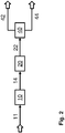
- FIG. 2 The block diagram shown according to a second example of the method or the plant according to the prior art is via line 11 the entire raw synthesis gas that is produced by means of a synthesis gas generation plant, not shown, for example as a steam reforming stage, as an autothermal reforming stage, as a partial oxidation stage or as a combination of at least two of the aforementioned synthesis gas generation stages is designed, led to a CO conversion plant 10 comprising at least one CO conversion stage and introduced into this. There is no handling around the CO conversion system in this exemplary embodiment.
- the raw synthesis gas stream is converted under CO conversion conditions into a converted synthesis gas stream, which is subsequently discharged from the CO conversion plant via line 14.
- a complete or partial conversion of CO to H 2 and CO 2 can be achieved, so that there are certain possibilities for setting the H 2 / CO ratio to be achieved in the synthesis gas product.
- the converted raw synthesis gas stream is introduced via line 14 into a sorption device 20 for removing acidic gas components, in particular carbon dioxide and hydrogen sulfide, by means of a physical or chemical sorption process.
- a sorption device 20 for removing acidic gas components, in particular carbon dioxide and hydrogen sulfide, by means of a physical or chemical sorption process.
- This can be configured, for example, as gas scrubbing with cryogenic methanol as an absorbent or washing agent according to the Rectisol process, which is known per se.
- a deacidified synthesis gas stream is then discharged from the sorption device via line 22 and introduced into a pressure swing adsorption system 40.
- the disadvantage of the in Fig. 2 The method shown is that, due to the low working pressure of the PSA, the synthesis gas product, for example the oxo gas, is obtained at low pressure and has to be compressed for subsequent use. Furthermore, purity requirements for the synthesis gas product often cannot be met, since it is obtained as it were as a waste product of the PSA, and the composition of the synthesis gas product fluctuates over time due to the cyclical operation of the PSA. Finally, the low availability of the synthesis gas product due to the combination of PSA and compressor is also disadvantageous.
- the synthesis gas product for example the oxo gas
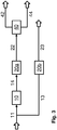
- the block diagram shown according to a third example of the method or the plant according to the prior art is a raw synthesis gas stream that was obtained by means of a synthesis gas generation plant, not shown, which is designed, for example, as a steam reforming stage, as an autothermal reforming stage, as a partial oxidation stage or as a combination of at least two of the aforementioned synthesis gas generation stages , divided into two parts, which are carried on via lines 11 and 13.
- the first portion is fed via line 11 to a CO conversion plant 10 comprising at least one CO conversion stage and introduced into it.
- Acid gas constituents in particular carbon dioxide and hydrogen sulfide, are removed in the first and second sorption devices 20a, 20b by means of a physical or chemical sorption process.
- the sorption devices can be designed, for example, as gas scrubbing with cryogenic methanol as the absorbent or washing agent according to the Rectisol process, which is known per se.
- a converted, deacidified synthesis gas stream is then discharged from the sorption device 20a via line 22 and introduced into a pressure swing adsorption system 40.
- the converted, deacidified synthesis gas stream is separated into a pure hydrogen product stream, which is discharged as a further product stream via line 42 from the pressure swing adsorption system and can be fed to a subsequent storage, treatment or further processing (not shown). Furthermore, a synthesis gas product stream is obtained, which is discharged from the pressure swing adsorption system via line 44 and can be fed to a subsequent storage, treatment or further processing (not shown). Due to its calorific value, it is often used as a fuel gas stream and fed into the synthesis gas generation plant, for example.
- the disadvantage of the in Fig. 3 The methods shown are in particular the specific high investment costs for the treatment of the synthesis gas product stream, in particular for the parallel operation of two sorption plants and furthermore when a small amount of the synthesis gas product is co-produced in addition to a large amount of pure hydrogen. There is little flexibility in varying the product quantities and there is no direct possibility of influencing the H 2 / CO ratio in the synthesis gas product. Furthermore, the high complexity of the process chain and the considerable costs that result from measures to ensure high availability of the synthesis gas product are also disadvantageous.
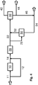
- Fig. 4 now shows an embodiment of a method and a plant according to the invention for producing a synthesis gas product stream with an adjustable H 2 / CO ratio, especially an oxo gas, and a pure hydrogen stream.
- a portion 1 of a raw synthesis gas which is configured as a steam reforming stage, as an autothermal reforming stage, as a partial oxidation stage or as a combination of at least two of the aforementioned synthesis gas production stages, by means of a synthesis gas generation plant (not shown), to at least one CO conversion stage, is via line 11 comprehensive CO conversion system 10 out and introduced into this.
- the design of the synthesis gas generation plant should, besides other aspects, also depend on the desired ratio of the synthesis gas product stream and the pure hydrogen stream as well as the desired H 2 / CO ratio of the synthesis gas product stream. If a large amount of a synthesis gas product is required that is to be used as an oxogas, this is recommended in particular the non-catalytic partial oxidation due to the raw synthesis gas produced with a high CO content.
- the introduced portion 1 of the raw synthesis gas stream is converted under CO conversion conditions to a converted synthesis gas stream, which is subsequently discharged from the CO conversion plant via line 14.
- the line 12 which is switched as a bypass or bypass, the remaining portion of the raw synthesis gas is led around the CO conversion plant and introduced directly into the line 14.
- the mixed gas stream obtained from converted synthesis gas and unconverted raw synthesis gas is introduced via line 14 into a sorption device 20 for removing acidic gas components, in particular carbon dioxide and hydrogen sulfide, by means of a physical or chemical sorption process.
- a sorption device 20 for removing acidic gas components, in particular carbon dioxide and hydrogen sulfide, by means of a physical or chemical sorption process.
- This can be configured, for example, as gas scrubbing with cryogenic methanol as an absorbent or scrubbing agent according to the Rectisol process, which is known per se.
- a deacidified synthesis gas stream is then discharged from the sorption device via line 22 and introduced into a pressure swing adsorption system 40.
- a portion 2 of the deacidified synthesis gas stream is introduced via line 25 into a first hydrogen enrichment stage 50 which contains a hydrogen-selective membrane as a separating element.
- the deacidified synthesis gas stream is separated into a hydrogen-enriched permeate stream, which is discharged via line 52 and, together with the deacidified synthesis gas stream conducted in line 22, is introduced into the pressure swing adsorption system, and into a retentate stream depleted in hydrogen, which is transferred as synthesis gas product stream
- Line 54 is diverted from the process and can be fed to a subsequent storage, treatment or further processing (not shown). In particular, this synthesis gas product stream is fed to a subsequent, not illustrated, plant for oxo synthesis.
- the hydrogen-enriched synthesis gas stream is separated into a pure hydrogen product stream, which is the next Product stream discharged from the pressure swing adsorption system via line 42 and can be fed to a subsequent storage, treatment or further processing (not shown). Furthermore, a residual gas stream is obtained which also comprises carbon monoxide and, if necessary, methane, argon and other impurities. It is discharged from the pressure swing adsorption system via line 44 and can be fed to a subsequent storage, treatment or further processing (not shown). Due to its calorific value, it is often used as a fuel gas stream and fed into the synthesis gas generation plant, for example.
- the setting of the molar H 2 / CO ratio required for the synthesis gas product stream is made possible by the fact that portion 1 and / or portion 2 is selected accordingly.
- a portion 3 of the carbon monoxide-containing residual gas stream is fed into the synthesis gas product stream and the portion 1 and / or the portion 2 and / or the portion 3 is selected so that the H 2 / CO required for the synthesis gas product stream Ratio results.
- the composition of the synthesis gas product can be changed and adjusted in a targeted and finely dosed manner, for example in order to generate an oxo gas with a predefined composition.
- This configuration is particularly advantageous when the residual gas flow has only a small proportion of impurities such as CO 2 , methane or argon. If necessary, these impurities can be removed by means of one or more cleaning stages, not shown in the illustration, so that the purity specifications for the oxo gas can be adhered to.
- the following product streams are generated from a raw synthesis gas stream of approx. 14,000 kmol / h with an H 2 content of approx. 40 mol% and a CO content of approx. 52 mol%: a pure hydrogen stream of approx. 9800 kmol /H with an H 2 content of 99.9 mol%, an oxo gas flow of approx. 1000 kmol / h with an H 2 content and a CO content of approx. 48 mol% each, a fuel gas flow of approx. 1900 kmol / h with an H 2 content of approx. 74 mol% and a CO content of approx. 25 mol%.
Landscapes
- Chemical & Material Sciences (AREA)
- Organic Chemistry (AREA)
- Engineering & Computer Science (AREA)
- Combustion & Propulsion (AREA)
- Chemical Kinetics & Catalysis (AREA)
- Inorganic Chemistry (AREA)
- General Chemical & Material Sciences (AREA)
- Oil, Petroleum & Natural Gas (AREA)
- Health & Medical Sciences (AREA)
- General Health & Medical Sciences (AREA)
- Hydrogen, Water And Hydrids (AREA)
Abstract
Description
- Die Erfindung betrifft ein Verfahren und eine Anlage zum Herstellen eines Synthesegasproduktstroms mit einstellbarem Wasserstoff-Kohlenmonoxid-Verhältnis und eines Reinwasserstoffstroms aus einem Kohlenwasserstoffe enthaltenden Einsatzstrom mittels eines Reformierungsverfahren (Dampfreformierung, autotherme Reformierung) oder eines Partialoxidationsverfahrens oder Mischungen dieser Verfahren.
- Die Erfindung betrifft ferner die Verwendung eines solchen Verfahrens bzw. einer solchen Anlage zum Herstellen eines als Oxogas geeigneten Synthesegasproduktstroms
- Als Synthesegase bezeichnet man Wasserstoff und Kohlenoxide enthaltende Gasgemische, die in verschiedenen Synthesereaktionen Verwendung finden. Beispiele hierfür sind die Methanolsynthese, die Oxosynthese oder die Fischer-Tropsch-Synthese.
- Bei der Oxosynthese, die auch als Hydroformylierung bezeichnet wird, handelt es sich gemäß der Internet-Enzyklopädie "Wikipedia", Schlagwort Hydroformylierung, abgerufen am 13.11.2019, um eine technisch bedeutende, homogen katalysierte Reaktion von Olefinen mit Kohlenmonoxid und Wasserstoff, die gemäß der folgenden, allgemeinen Reaktionsgleichung verläuft, aus der ersichtlich ist, dass aus stöchiometrischer Sicht für die Oxosynthese ein Synthesegas mit äquimolarem Kohlenmonoxid- und Wasserstoffgehalt benötigt wird.
CnH2n + CO + H2 = CnH2n+1CHO
- In der Praxis ist ein molares Verhältnis von Wasserstoff zu Kohlenstoffmonoxid von 1,5 mol/mol erwünscht. Der überschüssige Wasserstoff wird in der parallel ablaufenden Hydrierung der Aldehyde zu Alkoholen verbraucht.
- Die primären Produkte der Hydroformylierung sind Aldehyde mit einem Kohlenstoffatom mehr als das Ausgangsolefin. Diese Aldehyde werden zur Herstellung einer Vielzahl von Folgeprodukte verwendet und dabei oft zunächst zu den korrespondierenden Alkoholen hydriert. Wichtige industrielle Produkte der Hydroformylierung sind 1-Butanol und 2-Ethylhexanol, die beide aus Propen gewonnen werden. Als Hydroformylierungs-Katalysatoren werden in der großtechnischen Anwendung metallorganische Cobalt- oder Rhodiumverbindungen verwendet. Das industrielle Verfahren wird bei Drücken von etwa 10 bar bis 100 bar und Temperaturen zwischen 40 und 200 °C durchgeführt. Die Gesamtkapazität der existierenden Hydroformylierungsanlagen beträgt mehrere Millionen Tonnen pro Jahr.
- Zur Herstellung des benötigten Synthesegases kommen prinzipiell alle bekannten und in der industriellen Erzeugung angewandten Syntheseverfahren in Betracht, also insbesondere die Dampfreformierung von Kohlenwasserstoffen, insbesondere von Erdgas (Steam Methane Reforming, SMR) oder beispielsweise auch von Naphtha oder Raffineriereststoffen, die nichtkatalytische Partialoxidation von Kohlenwasserstoffen (POX) oder die autotherme Reformierung als Mischform beider vorgenannter Verfahren zum Einsatz. Technische Einzelheiten dieser Verfahren sind der Fachwelt bekannt und werden beispielsweise in Ullmann's Encyclopedia of Industrial Chemistry, Sixth Edition, 1998 Electronic Release, Stichwort "Gas Production", im Detail erläutert.
- Neben der Unterschiede im Verfahrensablauf sind ferner auch Unterschiede in der Zusammensetzung der erzeugten Synthesegasprodukte, insbesondere in dem erhaltenen Wasserstoff-Kohlenmonoxid-(H2/CO-)Verhältnis zu verzeichnen. Ausgehend von Methan als einfachstem einzusetzendem Kohlenwasserstoff lauten die Bruttoreaktionsgleichungen dieser Verfahren wie folgt:
2 CH4 + O2 = 2 CO + 4 H2 (Partialoxidation) 2 CH4 + ½ O2 + H2O = 2 CO + 5 H2 (autotherme Reformierung) 2 CH4 + 2 H2O = 2 CO + 6 H2 (reine Dampfreformierung) - Somit wird von keinem der Verfahren für sich betrachtet ein Synthesegasprodukt mit dem gewünschten, stöchiometrischen H2/CO-Verhältnis bzw. mit nur leichtem Wasserstoff-Überschuss erhalten. Um ein für die Oxosynthese einsetzbares Synthesegasprodukt zu erhalten, ist es daher erforderlich, einen Teil des Wasserstoffs abzutrennen, insbesondere dann, wenn bei der Aufbereitung oder Weiterverarbeitung des aus den oben genannten Verfahren erhaltenen Rohsynthesegases der Wasserstoffgehalt weiter erhöht wird. Ein Beispiel für eine solche Weiterverarbeitung ist die CO-Konvertierungsreaktion, auch als Wassergas-Shift-Reaktion (WGS) oder CO-Shift-Reaktion bezeichnet, gemäß der Umsatzgleichung
CO + H2O = CO2 + H2
- Unter Zugabe von Wasserdampf reagiert demnach das CO zu CO2 und H2. Aufgrund der Reaktionsenthalpie von -41,2 kJ/mol verschiebt sich das chemische Gleichgewicht mit steigender Temperatur von den Reaktionsprodukten hin zu den Reaktionsedukten. Je nach angewandter Reaktionstemperatur wird dabei von Hochtemperatur (HTS)-, Mitteltemperatur (MTS)- oder Tieftemperatur (LTS)-Shift gesprochen. Je nach Art der verwendeten Katalysatoren ist es ferner möglich, die Shift-Reaktion auch mit dem ungereinigten Rohsynthesegas durchzuführen. Dieses Verfahren wird als Rohgas-Shift oder auch - wegen der aciden Gasbestandteile, namentlich CO2 und H2S - als Sauergas-Shift bezeichnet.
- Die weitere Aufbereitung des erzeugten Rohsynthesegases umfasst zumeist auch ein Verfahren zur Abtrennung weiterer unerwünschter Begleitstoffe, beispielsweise mittels physikalischer oder chemischer Absorption oder Gaswäsche. So können mit solchen Verfahren unerwünschte, acide Bestandteile aus durch Vergasung oder Reformierung von kohlenstoffhaltigen Einsatzstoffen erzeugten Rohsynthesegasen, beispielsweise Kohlendioxid (CO2) und Schwefelwasserstoff (H2S), aber auch weitere Bestandteile wie Carbonylsulfid (COS), Cyanwasserstoff (HCN) oder Mercaptane (RSH), von den erwünschten Synthesegasbestandteilen Wasserstoff und Kohlenmonoxid sicher bis in den Spurenbereich entfernt werden. Ein bekanntes und häufig angewendetes Verfahren ist das Rectisol-Verfahren, das eine Wäsche des Rohsynthesegases mit tiefkaltem Methanol als Absorbens umfasst und ebenfalls im oben genannten Schrifttum grundsätzlich beschrieben wird.
- Zur Entfernung von Spuren höherer Kohlenwasserstoffe oder von Kohlenmonoxid kann die kryogene Gaszerlegung (sog. Coldbox) eingesetzt werden. Bei dieser wird hauptsächlich flüssiges Methan oder flüssiger Stickstoff verwendet, um höher siedende Gase wie Kohlenmonoxid zu absorbieren.
- Zur Herstellung von Reinwasserstoff folgt als abschließender Schritt üblicherweise die Behandlung des Rohwasserstoffstroms in einer Anlage zur Druckwechseladsorption (pressure swing adsorption, PSA), deren grundsätzliche Eigenschaften in dem Buch "Gasification", C. Higman und M. van der Burgt, Kapitel 8.2.3 "Adsorption systems", Gulf Professional Publishing (2003), dargestellt werden. Ihr optimaler Betriebsdruck liegt zwischen 15 und 30 bar, wobei dann Wasserstoffausbeuten zwischen 80 und 92 % erreicht werden können. Bei höheren Betriebsdrücken geht die Wasserstoffausbeute zurück. Die Temperatur des PSA-Feedgases liegt üblicherweise unter 40 °C, wobei entstehendes Kondensat zuvor abgetrennt wird.
- Die Druckwechseladsorption verwendet Molekularsiebe als Adsorbentien in einer Reihe von Behältern, die in einem gestaffelten zyklischen Modus betrieben werden, der zwischen einer Adsorptionsphase und verschiedenen Phasen der Regeneration wechselt. Die Regeneration des beladenen Adsorbens erfolgt durch schrittweise Druckentlastung und durch die Verwendung des Gases aus diesem Vorgang, um andere Adsorber im Regenerationszyklus mit einem anderen Druckniveau zu spülen. Die Wasserstoffrückgewinnung kann je nach Anzahl der Adsorber in einer Linie bis zu 90 % und bis zu 10 % betragen. Es kann eine sehr hohe Reinheit erreicht werden, mit etwa 50 ppm Argon und weniger als 10 ppm anderer Verunreinigungen.
- Die Herstellung eines für die Oxosynthese einsetzbaren Synthesegasprodukts neben einem Reinwasserstoffprodukt wird beispielsweise in der US-Patentanmeldung
US 2008/0272340 A1 beschrieben. Die dort offenbarte Erfindung betrifft ein Verfahren zur Herstellung von Synthesegas aus Kohlenwasserstoffen. Nach einer Ausführungsform der Erfindung umfasst die Synthesegasproduktionseinheit eine Vorrichtung zum Einstellen des H2/CO-Molverhältnisses des Synthesegases, beispielsweise zur Herstellung von Oxogas. Diese Vorrichtung umfasst eine wasserstoffdurchlässige Membran, wobei die Wasserstoffselektivität der Membran die Einstellung des gewünschten H2/CO-Molverhältnisses ermöglichen soll. Ferner wird bei der Membrantrennung des Rohsynthesegases auch ein Wasserstoffpermeat erhalten, der als Brennstoff genutzt wird, beispielsweise in einem Blockheizkraftwerk. Nachteilig ist hierbei die nur mit großem Aufwand mögliche Einstellung, insbesondere eine Feineinstellung des H2/CO-Molverhältnisses durch Austausch der Trennmembran und Ersatz gegen eine andere Membran, die aufgrund ihrer geänderten Wasserstoffselektivität die Einstellung des gewünschten H2/CO-Molverhältnisses ermöglicht. Der als Nebenprodukt erhaltene, gegenüber dem Rohsynthesegas an Wasserstoff angereicherte Permeatstrom wird lediglich thermisch als Brennstoff genutzt. Die Herstellung eines Synthesegasproduktes einstellbarer Zusammensetzung und eines Reinwasserstoffproduktes wird dagegen nicht offenbart. - Die Aufgabe der vorliegenden Erfindung besteht daher darin, ein Verfahren und eine Anlage zum Herstellen eines Synthesegasproduktstroms mit einstellbarem H2/CO-Verhältnis und eines Reinwasserstoffstroms anzugeben, die die erwähnten Nachteile des Stands der Technik nicht aufweisen.
- Diese Aufgabe wird in einem ersten Aspekt durch ein Verfahren mit den Merkmalen des Anspruchs 1 und mit einer Anlage mit den Merkmalen des Anspruchs 12 gelöst. Weitere Ausgestaltungen der Erfindung ergeben sich aus den Unteransprüchen der jeweiligen Kategorie. Die Erfindung betrifft auch die Verwendung des Verfahrens oder der Anlage gemäß der Erfindung zum Herstellen eines als Oxogas geeigneten Synthesegasproduktstroms.
- Die Synthesegaserzeugungsbedingungen, also die für die Durchführung der Dampfreformierung, des autothermen Reformierens (ATR) oder der partiellen, nichtkatalytischen Oxidation anzuwendenden Reaktions- und Verfahrensbedingungen dem Fachmann aus dem Stand der Technik, beispielsweise den eingangs erörterten Dokumenten, bekannt. Es sind diejenigen physikalisch-chemischen Bedingungen, unter denen ein messbarer, bevorzugt ein technisch relevanter Umsatz von Kohlenwasserstoffen zu Synthesegasprodukten erzielt wird. Notwendige Anpassungen dieser Bedingungen an die jeweiligen Betriebserfordernisse wird er auf der Grundlage von Routineversuchen vor-nehmen. Dabei können ggf. offenbarte, spezifische Reaktionsbedingungen als Orientierung dienen, sie sind aber in Bezug auf den Umfang der Erfindung nicht einschränkend zu verstehen. Dasselbe gilt für die CO-Konvertierungsbedingungen.
- Unter einer Sorptionsvorrichtung wird eine Vorrichtung verstanden, die zur Stofftrennung mittels physikalischer oder chemischen Adsorptions- oder Absorptionsverfahren bestimmt und geeignet ist, wobei unter der Adsorption das Anhaften an eine Oberfläche und unter der Absorption die Aufnahme in ein Phasenvolumen verstanden wird. Bei der chemischen Sorption erfolgt die Bindung der zu sorbierenden Komponente an das Sorptionsmittel oder Sorbens mittels spezifischer chemischer Wechselwirkungen jedweder Art, also beispielsweise mittels kovalenter Bindungen oder Wasserstoffbrückenbindungen. Alle anderen, nicht chemischen Sorptionsverfahren werden als physikalische Sorptionsverfahren verstanden.
- Unter einem Aufteilen oder Auftrennen bzw. Abtrennen eines Stoffstroms ist im Zusammenhang mit der vorliegenden Erfindung die Erzeugung mindestens zweier Teilströme aus dem ursprünglichen Stoffstrom zu verstehen, wobei mit dem Auftrennen bzw. Abtrennen eine beabsichtigte Änderung der stofflichen Zusammensetzung der erhaltenen Teilströme in Bezug auf den ursprünglichen Stoffstrom verbunden ist, beispielsweise durch Anwendung eines thermischen Trennverfahrens auf den ursprünglichen Stoffstrom. Dagegen ist mit dem Aufteilen des ursprünglichen Stoffstroms in der Regel keine Änderung der stofflichen Zusammensetzung der erhaltenen Teilströme verbunden.
- Die Angabe, dass ein Stoffstrom direkt einer spezifischen Verfahrensstufe oder einem spezifischen Anlagenteil zugeführt wird, ist so zu verstehen, dass der Stoffstrom in diese Verfahrensstufe oder diesen Anlagenteil eingeleitet wird, ohne dass zuvor ein Durchleiten durch andere Verfahrensstufen oder Anlagenteile erfolgte, mit Ausnahme reiner Transportvorgänge und der dazu benötigten Mittel, beispielsweise Rohrleitungen, Ventile, Pumpen, Verdichter, Vorratsbehälter.
- Alle etwaigen Druckangaben erfolgen als Absolutdruckeinheiten, abgekürzt bar, oder als Überdruckeinheiten, abgekürzt barg, wenn im jeweiligen Einzelzusammenhang nichts anderes angegeben wird.
- Unter Fluidverbindung zwischen zwei Bereichen der erfindungsgemäßen Vorrichtung wird dabei jegliche Art von Verbindung verstanden, die es ermöglicht, dass ein Fluid, beispielsweise ein Gasstrom, von dem einen zu dem anderen der beiden Bereiche strömen kann, unbeachtlich etwaiger zwischengeschalteter Bereiche oder Bauteile.
- Unter einem Mittel wird eine Sache verstanden, die die Erreichung eines Zieles ermöglicht oder dabei behilflich ist. Insbesondere werden unter Mitteln zum Durchführen eines bestimmten Verfahrensschrittes alle diejenigen physischen Gegenstände verstanden, die der Fachmann in Betracht ziehen würde, um diesen Verfahrensschritt durchführen zu können. Beispielsweise wird der Fachmann als Mittel zum Einleiten oder Ausleiten eines Stoffstroms alle Transport- und Fördervorrichtungen, also z. B. Rohrleitungen, Pumpen, Verdichter, Ventile, in Betracht ziehen, die ihm aufgrund seines Fachwissens zur Durchführung dieses Verfahrensschrittes notwendig oder sinnvoll erscheinen.
- Als Synthesegasproduktstrom, der als Oxogas für die Oxosynthese geeignet ist, wird ein Synthesegasproduktstrom aufgefasst, der die Anforderungen an ein gefordertes, molares H2/CO-Verhältnis erfüllt. Dies ist insbesondere dann der Fall, wenn das H2/CO-Verhältnis des Synthesegasproduktstroms zwischen 1,25 und 0,75 mol/mol beträgt. In der technischen Praxis der Oxosynthese ist ein molares Verhältnis von Wasserstoff zu Kohlenstoffmonoxid von beispielsweise 1,5 mol/mol erwünscht. Der hinsichtlich der Stöchiometrie der Hydroformylierungsreaktion überschüssige Wasserstoff wird in der parallel ablaufenden Hydrierung der Aldehyde zu Alkoholen verbraucht.
- Die Erfindung betrifft in einer bevorzugten Ausgestaltung die Erzeugung eines wasserstoffreichen Synthesegasgemisches durch Partialoxidation, allotherme oder autotherme Dampfreformierung von kohlenwasserstoffhaltigen Einsatzstoffen, gefolgt von partieller CO-Konvertierung (Wassergas-Shift-Konvertierung), Abtrennung saurer Gasbestandteile wie CO2 und ggf. H2S mittels eines Sorptionsverfahrens, beispielsweise mittels eines Gaswaschverfahrens wie des Rectisol-Verfahrens, und die Auftrennung dieses Synthesegasgemisches in ein beispielsweise für die Oxosynthese einsetzbares Synthesegas und Reinwasserstoff über eine Kombination zweier Wasserstoffanreicherungsstufen, die als Membrantrennung und Druckwechseladsorption ausgestaltet sind. Dieses Verfahren differenziert sich von Verfahrens des Stands der Technik durch den Verzicht auf kostenintensive Trennoperationen wie kryogene Gaszerlegungsverfahren oder eine getrennte Aufbereitung des Rohgases aus der Gaserzeugung für die jeweiligen Zielprodukte.
- Mittels der ersten Wasserstoffanreicherungsstufe, die als Membrantrennung ausgestaltet ist, kann ein Synthesegasprodukt mit der gewünschten Zusammensetzung direkt als Retentat aus wasserstoffreichem Rohsynthesegas bei hohem Produktdruck erzeugt werden. Das gegenüber dem Rohsynthesegas an Wasserstoff angereicherte Permeat wird, gegebenenfalls gemischt mit einem Teilstrom des Einsatzgases und/oder verdichtet, mittels der zweiten Wasserstoffanreicherungsstufe, einer Druckwechseladsorption (PSA), zu Wasserstoff hoher Reinheit aufbereitet. Der Rückstand aus der Druckwechseladsorption kann verdichtet und mit dem Synthesegasprodukt zusammengeführt oder anderweitig, beispielsweise als Brenngas, verwendet werden.
- Gemäß des Stands der Technik finden folgende Verfahrenssequenzen zur Erzeugung von Synthesegasprodukten mit oder ohne Koproduktion von Reinwasserstoff Anwendung:
- (a) Synthesegaserzeugung, ggf. partielle Wassergas-Shift-Konvertierung, CO2-Abtrennung, kryogene Zerlegung zur Trennung von Wasserstoff und CO zur Einstellung des H2/CO-Verhältnisses im Synthesegasprodukt (z. B. Oxogas), PSA zur Aufreinigung des verbleibenden Wasserstoffs. Nachteilig ist hierbei die Anwendung des kostenintensiven und hochkomplexen kyrogenen Zerlegungsverfahrens.
- (b) Synthesegaserzeugung, ggf. partielle Wassergas-Shift-Konvertierung, CO2-Abtrennung, PSA zur Abtrennung des Synthesegasprodukts mit bestimmtem H2/CO-Verhältnis und gleichzeitiger Aufreinigung des Wasserstoffs zur Gewinnung von Reinwasserstoff. Nachteilig ist es hierbei, dass bedingt durch den niedrigen Arbeitsdruck der PSA das Synthesegasprodukt, beispielsweise das Oxogas, bei niedrigem Druck erhalten wird und für die nachfolgende Verwendung verdichtet werden muss. Ferner können Reinheitsanforderungen für das Synthesegasprodukt häufig nicht erfüllt werden, da es gleichsam als Abfallprodukt der PSA erhalten wird, und es kommt aufgrund des zyklischen Betriebs der PSA zu zeitlichen Fluktuationen der Zusammensetzung des Synthesegasprodukts. Schließlich ist auch die niedrige Verfügbarkeit durch Kombination von PSA und Kompressor nachteilig. Das PSA-Verfahren basiert auf einer großen Anzahl aktiver Regelkomponenten, z. B. schnell schaltende Ventile, die verschleiß- und damit ausfallanfällig sind. Dies wird durch einen Notbetriebsmodus kompensiert, beispielsweise einen Notbetrieb mit nur einem Teil der üblichen Anzahl von Einzeladsorbern der Gesamtanlage. Hierbei wird Reinwasserstoff zwar mit der benötigten Reinheit, aber nur mit reduzierter Kapazität erhalten. Dadurch wird aber die Reinwasserstoff-Ausbeute herabgesetzt und somit die Zusammensetzung des Synthesegasprodukts deutlich verändert.
Kompressoren sind durch die Vielzahl an beweglichen mechanischen Elementen generell Risikokomponenten und werden deshalb oft mehrfach redundant ausgeführt, um länger andauernde Anlagenstillstände zu verhindern. Dies zieht erhöhte Investitionskosten nach sich. Außerdem kann das Umschalten auf den Reservekompressor häufig einen Anlagenausfall und -Neustart nicht verhindern. Die Redundanz dient in erster Linie der Verhinderung mehrwöchiger Stillstände. - (c) Synthesegaserzeugung, Auftrennung des Rohsynthesegases in zwei Teilströme, vollständige Wassergas-Shift-Konvertierung, CO2- und ggf. H2S-Abtrennung, Aufreinigung des ersten Teilstroms zu Reinwasserstoff mittels PSA, separate CO2- und ggf. H2S-Abtrennung zum Synthesegasprodukt für den zweiten Teilstrom. Nachteilig sind hier insbesondere die spezifisch hohen Investitionskosten für die Behandlung des Synthesegasprodukt-Stroms, insbesondere bei Koproduktion einer kleinen Menge des Synthesegasprodukts neben großen Menge an Reinwasserstoff. Es besteht nur eine geringe Flexibilität zur Variation der Produktmengen und es gibt keine direkte Möglichkeit zur Beeinflussung des H2/CO-Verhältnisses im Synthesegasprodukt. Ferner sind auch die hohe Komplexität der Verfahrenskette und die erheblichen Kosten von Nachteil, die aus Maßnahmen zur Sicherstellung einer hohen Verfügbarkeit des Synthesegasprodukts resultieren.
- Insbesondere die Kombination einer Synthesegaserzeugung auf Basis einer nichtkatalytischen Partialoxidation mit einer Gasreinigung, beispielweise mittels physikalischer Gaswäsche, bietet die Möglichkeit, auf einfache Weise ein H2/CO-Gemisch mit einem sehr niedrigen Anteil an Verunreinigungen zu erhalten. Ist Wasserstoff das Hauptprodukt der zu optimierenden Prozessschaltung, gestaltet sich die nachfolgende effiziente Abtrennung eines vergleichsweise kleinen Stroms mit niedrigem H2/CO-Verhältnis jedoch schwierig. Hier konnte entgegen der ursprünglichen Erwartung gefunden werden, dass eine Membrantrennung sehr gut für diese Aufgabenstellung geeignet ist, wobei das Permeat überraschend bei vergleichsweise hohem Druck erhalten wird und somit gut für die weitere Aufreinigung zu Wasserstoff geeignet ist.
- Das Verfahren und die Anlage gemäß der Erfindung zeichnen sich durch hohe Flexibilität aus. Sie ermöglichen die Anpassung des H2/CO-Verhältnisses im Rohsynthesegas durch partielle Wassergas-Shift-Konvertierung mit Bypass im Zusammenwirken mit der ersten und zweiten Wasserstoffanreicherungsstufe, insbesondere durch Einstellen bzw. Variieren der Druck- und Mengenstromverhältnisse in den als Membrantrennvorrichtung und PSA ausgestalteten Wasserstoffanreicherungsstufen. Je nach Anforderungen zu den Mengenverhältnissen der Produkte kann dabei die Verdichterleistung minimiert werden.
- Synthesegas wird erzeugt durch Partialoxidation oder Dampfreformierung oder autotherme Reformierung von kohlenwasserstoffhaltigen Einsatzstoffen. Aus dem erhaltenen Rohsynthesegas wird optional mittels CO-Konvertierung (Wassergas-Shift-Reaktion) mit einer geeigneten Anzahl von Konvertierungsstufen, typischerweise eine bis drei Konvertierungsstufen, und ggf. einem Bypass von unkonvertiertem Rohsynthesegas um die CO-Konvertierungsstufen herum, ein Molverhältnis von Wasserstoff zu Kohlenstoffmonoxid eingestellt, das demjenigen der Summe der gewünschten Produktströme entspricht. Aus diesem an Wasserstoff angereicherten Rohsynthesegas wird durch ein geeignetes Verfahren, beispielsweise eine chemische oder physikalische Wasche, saure Gasbestandteile wie CO2 sowie ggf. H2S abgetrennt. Der CO2-Gehalt des so gereinigten Gases orientiert sich an der geforderten Reinheit für das Synthesegasprodukt und kann beispielsweise bei Verwendung als Oxogas im Bereich von 1 bis 100 vol.-ppm liegen. Der Druck des gereinigten Synthesegasstroms orientiert sich an der Auswahl des Verfahrens zur Synthesegaserzeugung und dem gewünschten Lieferdruck für das Synthesegasprodukt und kann beispielsweise bei Verwendung als Oxogas im Bereich von 50 bar liegen. Ein Beispiel hierfür ist die Erzeugung von Hochdruck-Oxogas mittels POX.
- Ein Teilstrom des entsäuerten Synthesegases wird einer Membraneinheit zugeführt und ggf. auf eine für den Membran-Trennprozess geeignete Temperatur, z. B. 80 °C, aufgeheizt oder abgekühlt. Durch Auswahl von Membrantyp und Permeatdruck wird das H2/CO-Verhältnis im Retentat entsprechend der Produktspezifikation eingestellt, beispielsweise in einem Bereich von 0,75 bis 1,25, für viele Anwendungsfälle bei 1,0, für andere Anwendungsfälle bei 1,5. Gegebenenfalls kann anschließend eine Feinreinigung des als Retentat erhaltenen Oxogases erfolgen, beispielsweise durch Entfernung von Spuren von CO2 durch ein geeignetes Verfahren wie die Temperaturwechseladsorption.
- Das Permeat aus der Membran-Trenneinheit, das typischerweise bei einem Druck von 10 bis 30 bar anfällt, wird bei entsprechend hoher Anforderung bezüglich des Wasserstoff-Lieferdrucks oder zur Optimierung von Effizienz und Kosten der PSA-Einheit verdichtet, beispielsweise auf einen dem Synthesegasdruck entsprechendes Niveau von etwa 50 bar. Je nach Anforderungen bezüglich der Wasserstoff-Produktmenge kann das Permeat mit einem Teilstrom des entsäuerten Synthesegases aus der CO2-Abtrennung kombiniert werden und wird der PSA-Einheit zur Aufreinigung des Wasserstoffs zugeführt. Die Reinheit des resultierenden Wasserstoff-Stroms liegt typischerweise bei 99,9 %, die Rückgewinnungsrate der PSA-Einheit im Bereich von 80 bis über 90%. Das bei niedrigem Druck anfallende Restgas kann, ggf. nach Verdichtung, als Brenngas eingesetzt werden. Da bei geeigneter Wahl der Verteilung des Synthesegases auf Membran-Trennung und PSA-Trennung und der weiteren Prozessparameter wie Druckverhältnisse auch dieses Restgas in Qualität und Zusammensetzung nahe an diejenige des aus der Membran-Trenneinheit erhaltenen Synthesegasproduktstroms heranreichen kann, ist optional auch eine Verdichtung und Zusammenführung mit dem Synthesegasproduktstroms möglich, ggf. mit separater oder gemeinsamer Feinreinigung wie oben beschrieben. Art und Konzentrationen der möglichen Verunreinigungskomponenten können sich unterscheiden. Daher kann es sinnvoll sein, einen oder beide Ströme vor Zusammenführung getrennt zu reinigen, oder alternativ den kombinierten Strom gemeinsam zu reinigen, falls beispielsweise die Verunreinigungen sehr ähnlich sind. Für die Feinreinigung werden häufig vergleichsweise kostspielige feste Adsorbentien eingesetzt; daher sollte der zu behandelnde Gasstrom idealerweise möglichst klein und die Konzentration der zu entfernenden Komponente eher hoch sein. Eine Verdünnung des zu reinigenden Stroms mit einem bereits vergleichsweise sauberen Strom führt zu Kostensteigerung, da größere Adsorbensmengen und größere Behälter benötigt werden. In diesem Fall ist insbesondere die Gesamtleistung der Verdichter ein wichtiger Optimierungsparameter bei der Wahl der Prozessparameter für die Membran-PSA-Kombination.
- Ein zweiter Aspekt des erfindungsgemäßen Verfahrens ist dadurch gekennzeichnet, dass der Anteil 1, also der zu der CO-Konvertierungsanlage geführte Anteil des Rohsynthesegasstroms, zwischen 0 % und 100 % des Rohsynthesegasstroms beträgt und/oder der Anteil 2, also der zu der ersten Wasserstoffanreicherungsstufe geführte Anteil des entsäuerten Synthesegasstroms, zwischen 0 % und 100 % des entsäuerten Synthesegasstroms beträgt. Auf diese Weise kann die Zusammensetzung des Synthesegasprodukts in weiten Grenzen verändert und eingestellt werden.
- Ein dritter Aspekt des erfindungsgemäßen Verfahrens ist dadurch gekennzeichnet, dass ein Anteil 3 des Kohlenmonoxid enthaltenden Restgasstroms in den Synthesegasproduktstrom geführt wird und der Anteil 1 und/oder der Anteil 2 und/oder der Anteil 3 so gewählt wird, dass sich das für den Synthesegasproduktstrom geforderte H2/CO-Verhältnis ergibt. Auf diese Weise kann die Zusammensetzung des Synthesegasprodukts zielgerichtet verändert und eingestellt werden, beispielsweise um ein Oxogas mit vordefinierter Zusammensetzung zu erzeugen.
- Ein vierter Aspekt des erfindungsgemäßen Verfahrens ist dadurch gekennzeichnet, dass der Anteil 1 zwischen 0 % und 100 % des Rohsynthesegasstroms beträgt und/oder der Anteil 2 zwischen 0 % und 100 % des entsäuerten Synthesegasstroms beträgt und/oder der Anteil 3 zwischen 0 % und 100 % des Kohlenmonoxid enthaltenden Restgasstroms beträgt. Auf diese Weise ergeben sich zusätzliche Freiheitsgrade für die Einstellung der Zusammensetzung des Synthesegasprodukt in weiten Grenzen.
- Ein fünfter Aspekt des erfindungsgemäßen Verfahrens ist dadurch gekennzeichnet, dass das molare H2/CO-Verhältnis des Synthesegasproduktstroms zwischen 10 und 0,1 mol/mol, bevorzugt zwischen 5 und 0,5 mol/mol, weiter bevorzugt zwischen 2 und 1 mol/mol, meist bevorzugt zwischen 1,25 und 0,75 mol/mol beträgt. Somit kann zielgerichtet für unterschiedliche Verfahren, die Synthesegas unterschiedlicher Zusammensetzung als Einsatzstoff benötigen, die jeweils optimale Zusammensetzung eingestellt werden, beispielsweise die Methanolsynthese, die Fischer-Tropsch-Synthese oder die Oxosynthese.
- Ein sechster Aspekt des erfindungsgemäßen Verfahrens ist dadurch gekennzeichnet, dass der Rohsynthesegasstrom abzüglich des Anteils 1 direkt der Sorptionsvorrichtung zugeführt wird. Da hierbei dieser Stoffstrom unmittelbar der Sorptionsvorrichtung zugeführt wird, ohne dass zuvor ein Durchleiten durch andere Verfahrensstufen oder Anlagenteile erfolgt, werden unerwünschte Änderungen der Synthesegaszusammensetzung vermieden und es wird der Wasserstoffverlust und der Druckverlust minimiert und die Ausbeute des Verfahrens an Reinwasserstoff und seine Energieeffizienz erhöht.
- Ein siebter Aspekt des erfindungsgemäßen Verfahrens ist dadurch gekennzeichnet, dass der entsäuerte Synthesegasstrom abzüglich des Anteils 2 direkt der zweiten Wasserstoffanreicherungsstufe zugeführt wird. Da hierbei dieser Stoffstrom unmittelbar der der zweiten Wasserstoffanreicherungsstufe zugeführt wird, ohne dass zuvor ein Durchleiten durch andere Verfahrensstufen oder Anlagenteile erfolgt, werden unerwünschte Änderungen der Synthesegaszusammensetzung vermieden und es wird der Wasserstoffverlust und der Druckverlust minimiert und die Ausbeute des Verfahrens an Reinwasserstoff und seine Energieeffizienz erhöht.
- Ein achter Aspekt des erfindungsgemäßen Verfahrens ist dadurch gekennzeichnet, dass der Restgasstrom abzüglich des Anteils 3 als Brenngas aus dem Verfahren ausgeleitet wird. Hierdurch kann ein Reststoffstrom entsorgt und thermisch genutzt werden.
- Ein neunter Aspekt des erfindungsgemäßen Verfahrens ist dadurch gekennzeichnet, dass der Kohlenmonoxid enthaltende Restgasstrom vor Zuführen zum Synthesegasproduktstrom verdichtet wird. Hierdurch kann ein Reststoffstrom entsorgt und stofflich genutzt werden.
- Ein zehnter Aspekt des erfindungsgemäßen Verfahrens ist dadurch gekennzeichnet, dass der Kohlenmonoxid enthaltende Restgasstrom vor Zuführen zum Synthesegasproduktstrom einer Feinreinigungsstufe zugeführt wird oder nach Zuführen zum Synthesegasproduktstrom einer gemeinsamen Feinreinigungsstufe zugeführt wird. Die Feinreinigungsstufe kann dabei beispielsweise so ausgestaltet sein, dass z. B. Spuren von CO2 durch ein geeignetes Verfahren wie die Temperaturwechseladsorption entfernt werden können. Art und Konzentrationen der möglichen Verunreinigungskomponenten können sich unterscheiden. Daher kann es sinnvoll sein, einen oder beide Ströme vor Zusammenführung getrennt zu reinigen, oder alternativ den kombinierten Strom gemeinsam zu reinigen, falls beispielsweise die Verunreinigungen sehr ähnlich sind. Für die Feinreinigung werden häufig vergleichsweise kostspielige feste Adsorbentien eingesetzt; daher sollte der zu behandelnde Gasstrom idealerweise möglichst klein und die Konzentration der zu entfernenden Komponente eher hoch sein.
- Ein elfter Aspekt des erfindungsgemäßen Verfahrens ist dadurch gekennzeichnet, dass der an Wasserstoff angereicherte Permeatstrom vor Zuführen zu der zweiten Wasserstoffanreicherungsstufe verdichtet wird.
- In einem weiteren Aspekt ist die erfindungsgemäße Anlage dadurch gekennzeichnet, dass die Mittel zum Aufteilen des Rohsynthesegasstroms und die Mittel zum Aufteilen des entsäuerten Synthesegasstroms so beschaffen sind, dass der Anteil 1 und/oder der Anteil 2 so gewählt werden kann, dass sich das für den Synthesegasproduktstrom geforderte molare H2/CO-Verhältnis ergibt. Auf diese Weise kann die Zusammensetzung des Synthesegasprodukts zielgerichtet verändert und eingestellt werden, beispielsweise um ein Oxogas mit vordefinierter Zusammensetzung zu erzeugen.
- In einem weiteren Aspekt ist die erfindungsgemäße Anlage dadurch gekennzeichnet, dass ferner Mittel zum Aufteilen des Kohlenmonoxid enthaltenden Restgasstroms und Mittel zum Einleiten eines Anteils 3 Restgasstroms in den Synthesegasproduktstrom umfasst werden, wobei die Mittel so beschaffen sind, dass der Anteil 1 und/oder der Anteil 2 und/oder der Anteil 3 so gewählt werden kann, dass sich das für den Synthesegasproduktstrom geforderte H2/CO-Verhältnis ergibt. Auch auf diese Weise kann die Zusammensetzung des Synthesegasprodukts zielgerichtet verändert und eingestellt werden, beispielsweise um ein Oxogas mit vordefinierter Zusammensetzung zu erzeugen.
- In einem weiteren Aspekt ist die erfindungsgemäße Anlage dadurch gekennzeichnet, dass ferner Mittel umfasst werden, die es gestatten, dass der Kohlenmonoxid enthaltende Restgasstrom vor Zuführen zum Synthesegasproduktstrom verdichtet werden kann. Hierdurch kann ein Reststoffstrom entsorgt und stofflich genutzt werden.
- In einem weiteren Aspekt ist die erfindungsgemäße Anlage dadurch gekennzeichnet, dass ferner Mittel umfasst werden, die es gestatten, dass der Kohlenmonoxid enthaltende Restgasstrom vor Zuführen zum Synthesegasproduktstrom einer Feinreinigung unterzogen wird oder nach Zuführen zum Synthesegasproduktstrom einer gemeinsamen Feinreinigung unterzogen wird. Die Feinreinigungsstufe kann dabei beispielsweise so ausgestaltet sein, dass z. B. Spuren von CO2 durch ein geeignetes Verfahren wie die Temperaturwechseladsorption entfernt werden können. Art und Konzentrationen der möglichen Verunreinigungskomponenten können sich unterscheiden. Daher kann es sinnvoll sein, einen oder beide Ströme vor Zusammenführung getrennt zu reinigen, oder alternativ den kombinierten Strom gemeinsam zu reinigen, falls beispielsweise die Verunreinigungen sehr ähnlich sind. Für die Feinreinigung werden häufig vergleichsweise kostspielige feste Adsorbentien eingesetzt; daher sollte der zu behandelnde Gasstrom idealerweise möglichst klein und die Konzentration der zu entfernenden Komponente eher hoch sein.
- Weiterbildungen, Vorteile und Anwendungsmöglichkeiten der Erfindung ergeben sich auch aus der nachfolgenden Beschreibung von Ausführungsbeispielen und der Zeichnungen. Dabei bilden alle beschriebenen und/oder bildlich dargestellten Merkmale für sich oder in beliebiger Kombination die Erfindung, unabhängig von ihrer Zusammenfassung in den Ansprüchen oder deren Rückbeziehung.
- Es zeigen:
-
Fig. 1 ein erstes Beispiel eines Verfahrens bzw. einer Anlage zum Herstellen eines Oxogases gemäß Stand der Technik, -
Fig. 2 ein zweites Beispiel eines Verfahrens bzw. einer Anlage zum Herstellen eines Oxogases gemäß Stand der Technik, -
Fig. 3 ein drittes Beispiel eines Verfahrens bzw. einer Anlage zum Herstellen eines Oxogases gemäß Stand der Technik, -
Fig. 4 ein Ausführungsbeispiel eines Verfahrens bzw. einer Anlage gemäß der Erfindung zum Herstellen eines Oxogases. - Die
Figuren 1 bis 4 sind als Blockschaltbilder dargestellt, die die wesentlichen Funktionsblöcke und wichtige Verbindungsleitungen zwischen diesen zeigen, ohne das einzelne Armaturen und Ausrüstungsteile wie beispielsweise Wärmetauscher, Heizer, Kühler, Ventile, Mischvorrichtungen, Verbindungsvorrichtungen, Aufteilvorrichtungen, Pumpen, Gebläse, Verdichter separat dargestellt sind. Die benötigten Armaturen und Ausrüstungsteile wird der Fachmann anhand seines Fachwissens anhand seines Fachwissens über allgemeine Anforderungen des jeweiligen Funktionsblocks und/oder nachfolgende, spezifische Angaben auswählen und dimensionieren können. Dasselbe gilt für etwaige benötigte Hilfsstoffströme, beispielsweise den bei der CO-Konvertierung als Reaktionspartner benötigten Wasserdampf. - In dem in
Fig. 1 gezeigten Blockschaltbild gemäß eines ersten Beispiels des Verfahrens bzw. der Anlage gemäß Stand der Technik wird über Leitung 11 ein Anteil eines Rohsynthesegases, das mittels einer nicht bildlich dargestellten Synthesegaserzeugungsanlage, die beispielsweise als Dampfreformierungsstufe, als Autothermreformierungsstufe, als Partialoxidationsstufe oder als Kombination mindestens zweier der vorgenannten Synthesegaserzeugungsstufen ausgestaltet ist, zu einer mindestens eine CO-Konvertierungsstufe umfassenden CO-Konvertierungsanlage 10 geführt und in diese eingeleitet. In der CO-Konvertierungsanlage erfolgt das Umsetzen des eingeleiteten Anteils 1 des Rohsynthesegasstroms unter CO-Konvertierungsbedingungen zu einem konvertierten Synthesegasstrom, der nachfolgend über Leitung 14 aus der CO-Konvertierungsanlage ausgeleitet wird. Mittels der als Bypass bzw. Umgang geschalteten Leitung 12 wird der verbliebene Anteil des Rohsynthesegases um die CO-Konvertierungsanlage herumgeführt und direkt in die Leitung 14 eingeleitet. - Der aus konvertiertem Synthesegas und unkonvertiertem Rohsynthesegas erhaltene Mischgasstrom wird über Leitung 14 in eine in eine Sorptionsvorrichtung 20 zur Entfernung saurer Gasbestandteile, insbesondere Kohlendioxid und Schwefelwasserstoff, mittels eines physikalischen oder chemischen Sorptionsverfahrens eingeleitet. Diese kann beispielsweise als Gaswäsche mit tiefkaltem Methanol als Absorbens bzw. Waschmittel nach dem an sich bekannten Rectisol-Verfahren ausgestaltet werden. Über Leitung 22 erfolgt sodann das Ausleiten eines entsäuerten Synthesegasstroms aus der Sorptionsvorrichtung und das Einleiten in eine Anlage zur kryogenen Gaszerlegung 30.
- In der Anlage zur kryogenen Gaszerlegung, die beispielsweise als Flüssigmethanwäsche oder als Partialkondensation ausgestaltet sein kann, erfolgt die Abtrennung eines Synthesegasproduktstroms, beispielsweise eines Oxogasstroms, der über Leitung 34 aus dem Verfahren bzw. der Anlage ausgeleitet und einer nachfolgenden, nicht bildlich dargestellten Lagerung, Behandlung oder Weiterverarbeitung zugeführt werden kann. Ferner wird bei der kryogenen Gaszerlegung ein an Wasserstoff angereicherter Synthesegasstrom erhalten, der über Leitung 32 einer Druckwechseladsorptionsanlage 40 zugeführt wird.
- In der Druckwechseladsorptionsanlage erfolgt die Auftrennung des an Wasserstoff angereicherten Synthesegasstroms in einen Reinwasserstoffproduktstrom, der als weiterer Produktstrom über Leitung 42 aus der Druckwechseladsorptionsanlage ausgeleitet und einer nachfolgenden, nicht bildlich dargestellten Lagerung, Behandlung oder Weiterverarbeitung zugeführt werden kann. Ferner wird ein Restgasstrom erhalten, der noch Kohlenmonoxid und ggf. Methan, Argon und weitere Verunreinigungen umfasst. Er wird über Leitung 44 aus der Druckwechseladsorptionsanlage ausgeleitet und kann einer nachfolgenden, nicht bildlich dargestellten Lagerung, Behandlung oder Weiterverarbeitung zugeführt werden. Aufgrund seines Heizwertes wird er häufig als Brenngasstrom genutzt und beispielweise der Synthesegaserzeugungsanlage zugeführt.
- Nachteilig ist bei dem in
Fig. 1 gezeigten Verfahren die Anwendung des kostenintensiven und hochkomplexen kyrogenen Zerlegungsverfahrens. Eine Änderung der Zusammensetzung des Synthesegasprodukts ist nur schwierig und in engen Grenzen möglich und bedingt tiefe Eingriffe in die kryogene Gaszerlegung. - In dem in
Fig. 2 gezeigten Blockschaltbild gemäß eines zweiten Beispiels des Verfahrens bzw. der Anlage gemäß Stand der Technik wird über Leitung 11 das gesamte Rohsynthesegas, das mittels einer nicht bildlich dargestellten Synthesegaserzeugungsanlage, die beispielsweise als Dampfreformierungsstufe, als Autothermreformierungsstufe, als Partialoxidationsstufe oder als Kombination mindestens zweier der vorgenannten Synthesegaserzeugungsstufen ausgestaltet ist, zu einer mindestens eine CO-Konvertierungsstufe umfassenden CO-Konvertierungsanlage 10 geführt und in diese eingeleitet. Ein Umgang um die CO-Konvertierungsanlage herum fehlt in diesem Ausführungsbeispiel. - In der CO-Konvertierungsanlage erfolgt das Umsetzen des Rohsynthesegasstroms unter CO-Konvertierungsbedingungen zu einem konvertierten Synthesegasstrom, der nachfolgend über Leitung 14 aus der CO-Konvertierungsanlage ausgeleitet wird. Je nach Ausgestaltung und Durchführung der CO-Konvertierung kann entweder ein vollständiger oder partieller Umsatz von CO zu H2 und CO2 erzielt werden, so dass hierdurch gewisse Einstellmöglichkeiten für das zu erzielende H2/CO-Verhältnis im Synthesegasprodukt bestehen.
- Der konvertierte Rohsynthesegasstrom wird über Leitung 14 in eine in eine Sorptionsvorrichtung 20 zur Entfernung saurer Gasbestandteile, insbesondere Kohlendioxid und Schwefelwasserstoff, mittels eines physikalischen oder chemischen Sorptionsverfahrens eingeleitet. Diese kann beispielsweise als Gaswäsche mit tiefkaltem Methanol als Absorbens bzw. Waschmittel nach dem an sich bekannten Rectisol-Verfahren ausgestaltet werden. Über Leitung 22 erfolgt sodann das Ausleiten eines entsäuerten Synthesegasstroms aus der Sorptionsvorrichtung und das Einleiten in eine Druckwechseladsorptionsanlage 40.
- In der Druckwechseladsorptionsanlage erfolgt die Auftrennung des an Wasserstoff angereicherter Synthesegasstroms in einen Reinwasserstoffproduktstrom, der als Produktstrom über Leitung 42 aus der Druckwechseladsorptionsanlage ausgeleitet und einer nachfolgenden, nicht bildlich dargestellten Lagerung, Behandlung oder Weiterverarbeitung zugeführt werden kann. Ferner wird ein Synthesegasproduktstrom erhalten, der über Leitung 44 aus der Druckwechseladsorptionsanlage ausgeleitet wird und einer nachfolgenden, nicht bildlich dargestellten Lagerung, Behandlung oder Weiterverarbeitung zugeführt werden kann. Aufgrund seines Heizwertes wird er häufig als Brenngasstrom genutzt und beispielweise der Synthesegaserzeugungsanlage zugeführt.
- Nachteilig bei dem in
Fig. 2 gezeigten Verfahren ist es, dass bedingt durch den niedrigen Arbeitsdruck der PSA das Synthesegasprodukt, beispielsweise das Oxogas, bei niedrigem Druck erhalten wird und für die nachfolgende Verwendung verdichtet werden muss. Ferner können Reinheitsanforderungen für das Synthesegasprodukt häufig nicht erfüllt werden, da es gleichsam als Abfallprodukt der PSA erhalten wird, und es kommt aufgrund des zyklischen Betriebs der PSA zu zeitlichen Fluktuationen der Zusammensetzung des Synthesegasprodukts. Schließlich ist auch die niedrige Verfügbarkeit des Synthesegasprodukts durch Kombination von PSA und Kompressor nachteilig. - In dem in
Fig. 3 gezeigten Blockschaltbild gemäß eines dritten Beispiels des Verfahrens bzw. der Anlage gemäß Stand der Technik wird ein Rohsynthesegasstrom, der mittels einer nicht bildlich dargestellten Synthesegaserzeugungsanlage gewonnen wurde, die beispielsweise als Dampfreformierungsstufe, als Autothermreformierungsstufe, als Partialoxidationsstufe oder als Kombination mindestens zweier der vorgenannten Synthesegaserzeugungsstufen ausgestaltet ist, in zwei Anteile aufgeteilt, die über die Leitungen 11 und 13 weitergeführt werden. Über Leitung 11 wird der erste Anteil zu einer mindestens eine CO-Konvertierungsstufe umfassenden CO-Konvertierungsanlage 10 geführt und in diese eingeleitet. In der CO-Konvertierungsanlage erfolgt das Umsetzen des eingeleiteten Anteils des Rohsynthesegasstroms unter CO-Konvertierungsbedingungen zu einem konvertierten Synthesegasstrom, der nachfolgend über Leitung 14 aus der CO-Konvertierungsanlage ausgeleitet und in eine erste Sorptionsanlage 20a eingeleitet wird. Der verbliebene Anteil des Rohsynthesegasstroms, der unkonvertiert ist, wird über Leitung 13 in eine zweite Sorptionsanlage 20a eingeleitet. - In der ersten und zweiten Sorptionsvorrichtung 20a, 20b erfolgt eine Entfernung saurer Gasbestandteile, insbesondere Kohlendioxid und Schwefelwasserstoff, mittels eines physikalischen oder chemischen Sorptionsverfahrens. Die Sorptionsvorrichtungen können beispielsweise als Gaswäsche mit tiefkaltem Methanol als Absorbens bzw. Waschmittel nach dem an sich bekannten Rectisol-Verfahren ausgestaltet werden. Über Leitung 22 erfolgt sodann das Ausleiten eines konvertierten, entsäuerten Synthesegasstroms aus der Sorptionsvorrichtung 20a und das Einleiten in eine Druckwechseladsorptionsanlage 40. Über Leitung 23 wird dagegen ein unkonvertierter, entsäuerter Synthesegasstrom als Synthesegasprodukt aus der Sorptionsvorrichtung 20b aus dem Verfahren ausgeleitet und kann einer nachfolgenden, nicht bildlich dargestellten Lagerung, Behandlung oder Weiterverarbeitung, beispielsweise als Oxogas, zugeführt werden.
- In der Druckwechseladsorptionsanlage erfolgt die Auftrennung des konvertierten, entsäuerten Synthesegasstroms in einen Reinwasserstoffproduktstrom, der als weiterer Produktstrom über Leitung 42 aus der Druckwechseladsorptionsanlage ausgeleitet und einer nachfolgenden, nicht bildlich dargestellten Lagerung, Behandlung oder Weiterverarbeitung zugeführt werden kann. Ferner wird ein Synthesegasproduktstrom erhalten, der über Leitung 44 aus der Druckwechseladsorptionsanlage ausgeleitet wird und einer nachfolgenden, nicht bildlich dargestellten Lagerung, Behandlung oder Weiterverarbeitung zugeführt werden kann. Aufgrund seines Heizwertes wird er häufig als Brenngasstrom genutzt und beispielweise der Synthesegaserzeugungsanlage zugeführt.
- Nachteilig bei dem in
Fig. 3 gezeigten Verfahren sind insbesondere die spezifisch hohen Investitionskosten für die Behandlung des Synthesegasprodukt-Stroms, insbesondere für den Parallelbetrieb zweier Sorptionsanlagen und ferner bei Koproduktion einer kleinen Menge des Synthesegasprodukts neben großen Menge an Reinwasserstoff. Es besteht nur eine geringe Flexibilität zur Variation der Produktmengen und es gibt keine direkte Möglichkeit zur Beeinflussung des H2/CO-Verhältnisses im Synthesegasprodukt. Ferner sind auch die hohe Komplexität der Verfahrenskette und die erheblichen Kosten von Nachteil, die aus Maßnahmen zur Sicherstellung einer hohen Verfügbarkeit des Synthesegasprodukts resultieren. -
Fig. 4 zeigt nunmehr ein Ausführungsbeispiel eines Verfahrens bzw. einer Anlage gemäß der Erfindung zum Herstellen eines Synthesegasproduktstroms mit einstellbarem H2/CO-Verhältnis, speziell eines Oxogases, und eines Reinwasserstoffstroms. In dem gezeigten Blockschaltbild wird über Leitung 11 ein Anteil 1 eines Rohsynthesegases, das mittels einer nicht bildlich dargestellten Synthesegaserzeugungsanlage, die beispielsweise als Dampfreformierungsstufe, als Autothermreformierungsstufe, als Partialoxidationsstufe oder als Kombination mindestens zweier der vorgenannten Synthesegaserzeugungsstufen ausgestaltet ist, zu einer mindestens eine CO-Konvertierungsstufe umfassenden CO-Konvertierungsanlage 10 geführt und in diese eingeleitet. - Die Ausgestaltung der Synthesegaserzeugungsanlage sollte sich neben anderen Gesichtspunkten auch nach dem gewünschten Mengenverhältnis des Synthesegasproduktstroms und des Reinwasserstoffstroms sowie an dem angestrebten H2/CO-Verhältnis des Synthesegasproduktstroms richten. Wenn eine große Menge eines Synthesegasprodukts gefordert ist, das als Oxogas eingesetzt werden soll, empfiehlt sich insbesondere die nichtkatalytische Partialoxidation aufgrund des erzeugten Rohsynthesegases mit hohem CO-Gehalt.
- In der CO-Konvertierungsanlage erfolgt das Umsetzen des eingeleiteten Anteils 1 des Rohsynthesegasstroms unter CO-Konvertierungsbedingungen zu einem konvertierten Synthesegasstrom, der nachfolgend über Leitung 14 aus der CO-Konvertierungsanlage ausgeleitet wird. Mittels der als Bypass bzw. Umgang geschalteten Leitung 12 wird der verbliebene Anteil des Rohsynthesegases um die CO-Konvertierungsanlage herumgeführt und direkt in die Leitung 14 eingeleitet.
- Der aus konvertiertem Synthesegas und unkonvertiertem Rohsynthesegas erhaltene Mischgasstrom wird über Leitung 14 in eine in eine Sorptionsvorrichtung 20 zur Entfernung saurer Gasbestandteile, insbesondere Kohlendioxid und Schwefelwasserstoff, mittels eines physikalischen oder chemischen Sorptionsverfahrens eingeleitet. Diese kann beispielsweise als Gaswäsche mit tiefkaltem Methanol als Absorbens bzw. Waschmittel nach dem an sich bekannten Rectisol-Verfahren ausgestaltet werden. Über Leitung 22 erfolgt sodann das Ausleiten eines entsäuerten Synthesegasstroms aus der Sorptionsvorrichtung und das Einleiten in eine Druckwechseladsorptionsanlage 40. Zuvor wird jedoch über Leitung 25 ein Anteil 2 des entsäuerten Synthesegasstroms in eine erste Wasserstoffanreicherungsstufe 50 eingeleitet, die eine wasserstoffselektive Membran als Trennorgan enthält. In der ersten Wasserstoffanreicherungsstufe erfolgt das Auftrennen des entsäuerten Synthesegasstroms in einen an Wasserstoff angereicherten Permeatstrom, der über Leitung 52 ausgeleitet und gemeinsam mit dem in Leitung 22 geführten entsäuerten Synthesegasstrom in die Druckwechseladsorptionsanlage eingeleitet wird, und in einen an Wasserstoff abgereicherten Retentatstrom, der als Synthesegasproduktstrom über Leitung 54 aus dem Verfahren ausgeleitet wird und einer nachfolgenden, nicht bildlich dargestellten Lagerung, Behandlung oder Weiterverarbeitung zugeführt werden kann. Insbesondere wird dieser Synthesegasproduktstrom einer nachfolgenden, bildlich nicht dargestellten Anlage zur Oxosynthese zugeführt.
- In der Druckwechseladsorptionsanlage erfolgt die Auftrennung des an Wasserstoff angereicherten Synthesegasstroms in einen Reinwasserstoffproduktstrom, der als weiterer Produktstrom über Leitung 42 aus der Druckwechseladsorptionsanlage ausgeleitet und einer nachfolgenden, nicht bildlich dargestellten Lagerung, Behandlung oder Weiterverarbeitung zugeführt werden kann. Ferner wird ein Restgasstrom erhalten, der noch Kohlenmonoxid und ggf. Methan, Argon und weitere Verunreinigungen umfasst. Er wird über Leitung 44 aus der Druckwechseladsorptionsanlage ausgeleitet und kann einer nachfolgenden, nicht bildlich dargestellten Lagerung, Behandlung oder Weiterverarbeitung zugeführt werden. Aufgrund seines Heizwertes wird er häufig als Brenngasstrom genutzt und beispielweise der Synthesegaserzeugungsanlage zugeführt.
- Das Einstellen des für den Synthesegasproduktstrom geforderten, molaren H2/CO-Verhältnis wird dadurch ermöglicht, dass der Anteil 1 und/oder der Anteil 2 entsprechend gewählt wird.
- Möglich ist es aber auch, dass ein Anteil 3 des Kohlenmonoxid enthaltenden Restgasstroms in den Synthesegasproduktstrom geführt wird und der Anteil 1 und/oder der Anteil 2 und/oder der Anteil 3 so gewählt wird, dass sich das für den Synthesegasproduktstrom geforderte H2/CO-Verhältnis ergibt. Auf diese Weise kann die Zusammensetzung des Synthesegasprodukts zielgerichtet und fein dosiert verändert und eingestellt werden, beispielsweise um ein Oxogas mit vordefinierter Zusammensetzung zu erzeugen. Diese Ausgestaltung ist insbesondere dann vorteilhaft, wenn der Restgasstrom nur einen geringen Anteil an Verunreinigungen wie CO2, Methan oder Argon aufweist. Gegebenenfalls können diese Verunreinigungen mittels einer oder mehrerer, bildlich nicht gezeigter Reinigungsstufen entfernt werden, so dass die Reinheitsspezifikationen für das Oxogas eingehalten werden können.
- In der nachfolgenden Tabelle sind für ein erfindungsgemäßes Verfahren bzw. eine entsprechende Anlage gemäß
Fig. 4 die Zusammensetzungen einzelner Stoffströme und deren Gesamtstoffmengenströme und Drücke zusammengestellt. - Im vorliegenden Zahlenbeispiel werden aus einem Rohsynthesegasstrom von ca. 14000 kmol/h mit einem H2-Gehalt von ca. 40 mol-% und einem CO-Gehalt von ca. 52 mol-% folgende Produktströme erzeugt: ein Reinwasserstoffstrom von ca. 9800 kmol/h mit einem H2-Gehalt von 99,9 mol-%, ein Oxogasstrom von ca. 1000 kmol/h mit einem H2-Gehalt und einem CO-Gehalt von jeweils ca. 48 mol-%, ein Brenngasstrom von ca. 1900 kmol/h mit einem H2-Gehalt von ca. 74 mol-% und einem CO-Gehalt von ca. 25 mol-%.
-
- [10]
- CO-Konvertierungsanlage
- [11] - [14]
- Leitung
- [20]
- Sorptionsvorrichtung
- [20a]
- Sorptionsvorrichtung
- [20b]
- Sorptionsvorrichtung
- [22] - [23]
- Leitung
- [25]
- Leitung
- [30]
- Anlage zur kryogenen Gaszerlegung
- [32]
- Leitung
- [34]
- Leitung
- [40]
- Druckwechseladsorptionsanlage
- [42]
- Leitung
- [44]
- Leitung
- [46]
- Leitung
- [50]
- Membrantrennanlage
- [52]
- Leitung
- [54]
- Leitung
- Strom in Leitung 42 (Reinwasserstoff): Konzentration CO < 10 ppm gemäß Spezifikation für Reinwasserstoff. Ströme in Leitungen 22, 25, 44, 52, 54: Konzentration CO2 < 10ppm gemäß Spezifikation für Oxogas.
| Leitung | Nr. | 11 | 14 | 22 + 25 | 25 | 54 | 52 | 22 | 22 + 52 | 44 | 42 |
| von Block | Nr. | AG | 10 | 20 | 20 | 50 | 50 | 20 | 20 + 50 | 40 | 40 |
| zu Block | Nr. | 10 | 20 | 40 | 50 | AG | 40 | 40 | 40 | AG | AG |
| H2 | mol-% | 39,9 | 92,7 | 91,8 | 91,8 | 48,2 | 98,5 | 91,8 | 95,6 | 73,7 | 99,9 |
| CO | mol-% | 51,9 | 5,0 | 7,7 | 7,7 | 48,2 | 1,5 | 7,7 | 4,1 | 25,2 | < 10 ppm |
| CO2 | mol-% | 5 | 34,6 | < 10 ppm | < 10 ppm | < 10 ppm | < 10 ppm | < 10 ppm | < 10 ppm | < 10 ppm | 0,0 |
| CH4 | mol-% | 0,3 | 0,2 | 0,3 | 0,3 | 1,9 | 0,0 | 0,3 | 0,1 | 0,8 | 0,0 |
| Rest (N2, Ar) | mol-% | 2,9 | 2,0 | 0,3 | 0,3 | 1,3 | 0,0 | 0,3 | 0,1 | 0,3 | 0,1 |
| Gesamtstrom "trocken" | kmol/h | 14012 | 20284 | 12791 | 7720 | 1023 | 6698 | 5070 | 11765 | 1928 | 9839 |
| Druck | barg | 54 | 50 | 48 | 48 | 46 | 20 | 48 | 48 | 0,5 | 47 |
| AG = Anlagengrenze |
Claims (17)
- Verfahren zum Herstellen eines Synthesegasproduktstroms mit einstellbarem Wasserstoff-Kohlenmonoxid-Verhältnis (H2/CO-Verhältnis) und eines Reinwasserstoffstroms aus einem Kohlenwasserstoffe enthaltenden Einsatzstrom, umfassend folgende Schritte:(a) Bereitstellen des Kohlenwasserstoffe enthaltenden Einsatzstroms,(b) Zuführen des Kohlenwasserstoffe enthaltenden Einsatzstroms zu einer Synthesegaserzeugungsanlage, umfassend(b1) eine Dampfreformierungsstufe oder(b2) eine Autothermreformierungsstufe (ATR) oder(b3) eine Partialoxidationsstufe (POX) oder(b4) eine Kombination von mindestens zwei der Stufen (b1) bis (b3),(c) mindestens teilweises Umsetzen des Kohlenwasserstoffe enthaltenden Einsatzstroms in der Synthesegaserzeugungsanlage unter Synthesegaserzeugungsbedingungen zu einem Wasserstoff (H2) und Kohlenmonoxid (CO) enthaltenden Rohsynthesegasstrom,(d) Ausleiten eines Rohsynthesegasstroms aus der Synthesegaserzeugungsanlage,(e) Einleiten mindestens eines Anteils 1 des Rohsynthesegasstroms in eine CO-Konvertierungsanlage, umfassend mindestens eine CO-Konvertierungsstufe, Umsetzen des in die CO-Konvertierungsanlage eingeleiteten Anteils des Rohsynthesegasstroms unter CO-Konvertierungsbedingungen zu einem konvertierten Synthesegasstrom, Ausleiten des konvertierten Synthesegasstroms,(f) Einleiten des Rohsynthesegasstroms und/oder des konvertierten Synthesegasstroms in eine Sorptionsvorrichtung zur Entfernung saurer Gasbestandteile, insbesondere Kohlendioxid und Schwefelwasserstoff, mittels eines physikalischen oder chemischen Sorptionsverfahrens, Ausleiten eines entsäuerten Synthesegasstroms aus der Sorptionsvorrichtung,(g) Einleiten mindestens eines Anteils 2 des entsäuerten Synthesegasstroms in eine erste Wasserstoffanreicherungsstufe, enthaltend eine wasserstoffselektive Membran als Trennorgan, Auftrennen des entsäuerten Synthesegasstroms in einen an Wasserstoff angereicherten Permeatstrom und in einen an Wasserstoff abgereicherten Retentatstrom,(h) Einleiten des an Wasserstoff angereicherten Permeatstroms und des nicht zu der ersten Wasserstoffanreicherungsstufe geführten Anteils des entsäuerten Synthesegasstroms in eine zweite, nach dem Prinzip der Druckwechseladsorption (PSA) arbeitenden Wasserstoffanreicherungsstufe,(i) Ausleiten eines Reinwasserstoffstroms und eines Kohlenmonoxid enthaltenden Restgasstroms aus der zweiten Wasserstoffanreicherungsstufe,(j) Ausleiten des an Wasserstoff abgereicherten Retentatstroms aus der ersten Wasserstoffanreicherungsstufe als Synthesegasproduktstrom,(k) wobei der Anteil 1 und/oder der Anteil 2 so gewählt wird, dass sich das für den Synthesegasproduktstrom geforderte molare H2/CO-Verhältnis ergibt.
- Verfahren nach Anspruch 1, dadurch gekennzeichnet, dass der Anteil 1 zwischen 0 % und 100 % des Rohsynthesegasstroms beträgt und/oder der Anteil 2 zwischen 0 % und 100 % des entsäuerten Synthesegasstroms beträgt.
- Verfahren nach Anspruch 1 oder 2, dadurch gekennzeichnet, dass ein Anteil 3 des Kohlenmonoxid enthaltenden Restgasstroms in den Synthesegasproduktstrom geführt wird und der Anteil 1 und/oder der Anteil 2 und/oder der Anteil 3 so gewählt wird, dass sich das für den Synthesegasproduktstrom geforderte H2/CO-Verhältnis ergibt.
- Verfahren nach Anspruch 3, dadurch gekennzeichnet, dass der Anteil 1 zwischen 0 % und 100 % des Rohsynthesegasstroms beträgt und/oder der Anteil 2 zwischen 0 % und 100 % des entsäuerten Synthesegasstroms beträgt und/oder der Anteil 3 zwischen 0 % und 100 % des Kohlenmonoxid enthaltenden Restgasstroms beträgt.
- Verfahren nach einem der Ansprüche 1 bis 3, dadurch gekennzeichnet, dass molare H2/CO-Verhältnis des Synthesegasproduktstroms zwischen 10 und 0,1 mol/mol, bevorzugt zwischen 5 und 0,5 mol/mol, weiter bevorzugt zwischen 2 und 1 mol/mol, meist bevorzugt zwischen 1,25 und 0,75 mol/mol beträgt.
- Verfahren nach einem der vorigen Ansprüche, dadurch gekennzeichnet, dass der Rohsynthesegasstrom abzüglich des Anteils 1 direkt der Sorptionsvorrichtung zugeführt wird.
- Verfahren nach einem der vorigen Ansprüche, dadurch gekennzeichnet, dass der entsäuerte Synthesegasstrom abzüglich des Anteils 2 direkt der zweiten Wasserstoffanreicherungsstufe zugeführt wird.
- Verfahren nach einem der vorigen Ansprüche, dadurch gekennzeichnet, dass der Restgasstrom abzüglich des Anteils 3 als Brenngas aus dem Verfahren ausgeleitet wird.
- Verfahren nach einem der vorigen Ansprüche, dadurch gekennzeichnet, dass der Kohlenmonoxid enthaltende Restgasstrom vor Zuführen zum Synthesegasproduktstrom verdichtet wird.
- Verfahren nach einem der vorherigen Ansprüche, dadurch gekennzeichnet, dass der Kohlenmonoxid enthaltende Restgasstrom vor Zuführen zum Synthesegasproduktstrom einer Feinreinigungsstufe zugeführt wird oder nach Zuführen zum Synthesegasproduktstrom einer gemeinsamen Feinreinigungsstufe zugeführt wird.
- Verfahren nach einem der vorigen Ansprüche, dadurch gekennzeichnet, dass der an Wasserstoff angereicherte Permeatstrom vor Zuführen zu der zweiten Wasserstoffanreicherungsstufe verdichtet wird.
- Anlage zum Herstellen eines Synthesegasproduktstroms mit einstellbarem Wasserstoff-Kohlenmonoxid-Verhältnis (H2/CO-Verhältnis) und eines Reinwasserstoffstroms aus einem Kohlenwasserstoffe enthaltenden Einsatzstrom, umfassend folgende, miteinander in Fluidverbindung stehende Baugruppen und Bestandteile:(a) Mittel zum Bereitstellen des Kohlenwasserstoffe enthaltenden Einsatzstroms,(b) eine Synthesegaserzeugungsanlage, umfassend:(b1) eine Dampfreformierungsstufe (SMR) oder(b2) eine Autothermreformierungsstufe (ATR) oder(b3) eine Partialoxidationsstufe (POX) oder(b4) eine Kombination von mindestens zwei der Stufen (b1) bis (b3),Mittel zum Zuführen des Kohlenwasserstoffe enthaltenden Einsatzstroms zu der Synthesegaserzeugungsanlage,(c) Mittel zum Ausleiten eines Rohsynthesegasstroms, enthaltend Wasserstoff (H2) und Kohlenmonoxid (CO) aus der Synthesegaserzeugungsanlage,(d) eine CO-Konvertierungsanlage, umfassend mindestens eine CO-Konvertierungsstufe, Mittel zum Aufteilen des Rohsynthesegasstroms und Mittel Einleiten mindestens eines Anteils 1 des Rohsynthesegasstroms in die CO-Konvertierungsanlage, Mittel zum Ausleiten eines konvertierten Synthesegasstroms,(e) eine Sorptionsvorrichtung, geeignet zur Entfernung saurer Gasbestandteile, insbesondere Kohlendioxid und Schwefelwasserstoff, mittels eines physikalischen oder chemischen Sorptionsverfahrens, Mittel zum Einleiten des Rohsynthesegasstroms und/oder des konvertierten Synthesegasstroms in die Sorptionsvorrichtung, Mittel zum Ausleiten eines entsäuerten Synthesegasstroms aus der Sorptionsvorrichtung,(f) eine erste Wasserstoffanreicherungsstufe, enthaltend eine wasserstoffselektive Membran als Trennorgan, geeignet zum Auftrennen des entsäuerten Synthesegasstroms in einen an Wasserstoff angereicherten Permeatstrom und in einen an Wasserstoff abgereicherten Retentatstrom, Mittel zum Aufteilen des entsäuerten Synthesegasstroms und Mittel zum Einleiten mindestens eines Anteils 2 des entsäuerten Synthesegasstroms in die erste Wasserstoffanreicherungsstufe, Mittel zum Ausleiten des an Wasserstoff angereicherten Permeatstroms und des an Wasserstoff abgereicherten Retentatstroms,(g) eine zweite, nach dem Prinzip der Druckwechseladsorption (PSA) arbeitende Wasserstoffanreicherungsstufe, Mittel zum Einleiten des an Wasserstoff angereicherten Permeatstroms und des nicht zu der ersten Wasserstoffanreicherungsstufe geführten Anteils des entsäuerten Synthesegasstroms in die zweite Wasserstoffanreicherungsstufe,(h) Mittel zum Ausleiten eines Reinwasserstoffstroms und eines Kohlenmonoxid enthaltenden Restgasstroms aus der zweiten Wasserstoffanreicherungsstufe,(i) Mittel zum Ausleiten des an Wasserstoff abgereicherten Retentatstroms aus der ersten Wasserstoffanreicherungsstufe als Synthesegasproduktstrom.
- Anlage nach Anspruch 12, dadurch gekennzeichnet, dass die Mittel zum Aufteilen des Rohsynthesegasstroms und die Mittel zum Aufteilen des entsäuerten Synthesegasstroms so beschaffen sind, dass der Anteil 1 und/oder der Anteil 2 so gewählt werden kann, dass sich das für den Synthesegasproduktstrom geforderte molare H2/CO-Verhältnis ergibt.
- Anlage nach Anspruch 12 oder 13, dadurch gekennzeichnet, dass ferner Mittel zum Aufteilen des Kohlenmonoxid enthaltenden Restgasstroms und Mittel zum Einleiten eines Anteils 3 Restgasstroms in den Synthesegasproduktstrom umfasst werden, wobei die Mittel so beschaffen sind, dass der Anteil 1 und/oder der Anteil 2 und/oder der Anteil 3 so gewählt werden kann, dass sich das für den Synthesegasproduktstrom geforderte H2/CO-Verhältnis ergibt.
- Anlage nach einem der vorigen Ansprüche, dadurch gekennzeichnet, dass ferner Mittel umfasst werden, die es gestatten, dass der Kohlenmonoxid enthaltende Restgasstrom vor Zuführen zum Synthesegasproduktstrom verdichtet werden kann.
- Anlage nach einem der vorigen Ansprüche, dadurch gekennzeichnet, dass ferner Mittel umfasst werden, die es gestatten, dass der Kohlenmonoxid enthaltende Restgasstrom vor Zuführen zum Synthesegasproduktstrom einer Feinreinigung unterzogen wird oder nach Zuführen zum Synthesegasproduktstrom einer gemeinsamen Feinreinigung unterzogen wird.
- Verwendung eines Verfahrens gemäß eines der Ansprüche 1 bis 10 oder einer Anlage gemäß der Ansprüche 12 bis 16 zum Herstellen eines als Oxogas geeigneten Synthesegasproduktstroms.
Priority Applications (3)
| Application Number | Priority Date | Filing Date | Title |
|---|---|---|---|
| EP19020688.8A EP3835258B1 (de) | 2019-12-11 | 2019-12-11 | Verfahren und anlage zum herstellen eines synthesegasproduktstroms mit einstellbarem h2/co-verhältnis und eines reinwasserstoffstroms |
| SG10202011476PA SG10202011476PA (en) | 2019-12-11 | 2020-11-18 | Process and plant for producing a synthesis gas product stream having an adjustable H2/CO ratio and a pure hydrogen stream |
| US17/117,526 US11667526B2 (en) | 2019-12-11 | 2020-12-10 | Process and plant for producing a synthesis gas product stream having an adjustable H2/CO ratio and a pure hydrogen stream |
Applications Claiming Priority (1)
| Application Number | Priority Date | Filing Date | Title |
|---|---|---|---|
| EP19020688.8A EP3835258B1 (de) | 2019-12-11 | 2019-12-11 | Verfahren und anlage zum herstellen eines synthesegasproduktstroms mit einstellbarem h2/co-verhältnis und eines reinwasserstoffstroms |
Publications (2)
| Publication Number | Publication Date |
|---|---|
| EP3835258A1 true EP3835258A1 (de) | 2021-06-16 |
| EP3835258B1 EP3835258B1 (de) | 2023-08-09 |
Family
ID=68886685
Family Applications (1)
| Application Number | Title | Priority Date | Filing Date |
|---|---|---|---|
| EP19020688.8A Active EP3835258B1 (de) | 2019-12-11 | 2019-12-11 | Verfahren und anlage zum herstellen eines synthesegasproduktstroms mit einstellbarem h2/co-verhältnis und eines reinwasserstoffstroms |
Country Status (3)
| Country | Link |
|---|---|
| US (1) | US11667526B2 (de) |
| EP (1) | EP3835258B1 (de) |
| SG (1) | SG10202011476PA (de) |
Cited By (2)
| Publication number | Priority date | Publication date | Assignee | Title |
|---|---|---|---|---|
| EP4197619A1 (de) * | 2021-12-20 | 2023-06-21 | Evonik Operations GmbH | Verfahren zur herstellung von kohlenmonoxid-haltigen strömen |
| EP4469393A4 (de) * | 2022-01-28 | 2026-02-18 | M2X Energy Inc | Systeme, vorrichtungen und verfahren zur eingangs- und ausgangsdruckverwaltung von reformern für luftatmungsmotoren |
Families Citing this family (11)
| Publication number | Priority date | Publication date | Assignee | Title |
|---|---|---|---|---|
| CA3042969A1 (en) | 2016-11-09 | 2018-05-17 | 8 Rivers Capital, Llc | Systems and methods for power production with integrated production of hydrogen |
| JP7297775B2 (ja) | 2017-11-09 | 2023-06-26 | 8 リバーズ キャピタル,エルエルシー | 水素および二酸化炭素の生成および分離のためのシステムおよび方法 |
| KR20220020842A (ko) | 2019-06-13 | 2022-02-21 | 8 리버스 캐피탈, 엘엘씨 | 추가 생성물들의 공동 발생을 구비하는 동력 생산 |
| CN113735060A (zh) * | 2021-10-09 | 2021-12-03 | 天邦膜技术国家工程研究中心有限责任公司 | 一种膜分离和变压吸附耦合调节合成气氢碳比同时副产氢气的系统 |
| AU2022394811A1 (en) | 2021-11-18 | 2024-06-27 | 8 Rivers Capital, Llc | Apparatus for hydrogen production |
| CN114045182B (zh) * | 2021-12-01 | 2022-10-14 | 中国农业科学院农业环境与可持续发展研究所 | 一种热解气回流协同二级吸附固碳减排方法 |
| EP4444687A1 (de) | 2022-02-27 | 2024-10-16 | Petrosakht Chehelsoton Engineering Technical Company | Integriertes verfahren zur herstellung von oxoalkoholen aus erdgas |
| WO2024147765A1 (en) * | 2023-01-04 | 2024-07-11 | TEMEL, Erdal | Process for handling label waste |
| WO2025078974A2 (en) | 2023-10-09 | 2025-04-17 | 8 Rivers Capital, Llc | Systems and methods for producing hydrogen with integrated capture of carbon dioxide |
| WO2025194079A1 (en) * | 2024-03-15 | 2025-09-18 | Basf Corporation | Process for generating syngas from waste streams |
| WO2026093123A1 (en) * | 2024-10-31 | 2026-05-07 | Topsoe A/S | Plant and process for producing a synthesis gas with low carbon intensity (ci) |
Citations (4)
| Publication number | Priority date | Publication date | Assignee | Title |
|---|---|---|---|---|
| US5888470A (en) * | 1995-10-26 | 1999-03-30 | L'air Liquide, Societe Anonyme Pour L'etude Et L'exploitation Des Procedes Georges Claude | Process for the production of hydrogen and of energy |
| US20060194889A1 (en) * | 2005-02-25 | 2006-08-31 | Chang-Jie Guo | Novel membrane-enhanced liquid production for syngas hubs |
| US20080272340A1 (en) | 2005-02-01 | 2008-11-06 | Daphne Koh | Method for Producing Syngas with Low Carbon Dioxide Emission |
| US20110271714A1 (en) * | 2003-04-03 | 2011-11-10 | Fluor Technologies Corporation | Configurations and Methods of Carbon Capture |
Family Cites Families (1)
| Publication number | Priority date | Publication date | Assignee | Title |
|---|---|---|---|---|
| US10738247B2 (en) * | 2017-11-15 | 2020-08-11 | Gas Technology Institute | Processes and systems for reforming of methane and light hydrocarbons to liquid hydrocarbon fuels |
-
2019
- 2019-12-11 EP EP19020688.8A patent/EP3835258B1/de active Active
-
2020
- 2020-11-18 SG SG10202011476PA patent/SG10202011476PA/en unknown
- 2020-12-10 US US17/117,526 patent/US11667526B2/en active Active
Patent Citations (4)
| Publication number | Priority date | Publication date | Assignee | Title |
|---|---|---|---|---|
| US5888470A (en) * | 1995-10-26 | 1999-03-30 | L'air Liquide, Societe Anonyme Pour L'etude Et L'exploitation Des Procedes Georges Claude | Process for the production of hydrogen and of energy |
| US20110271714A1 (en) * | 2003-04-03 | 2011-11-10 | Fluor Technologies Corporation | Configurations and Methods of Carbon Capture |
| US20080272340A1 (en) | 2005-02-01 | 2008-11-06 | Daphne Koh | Method for Producing Syngas with Low Carbon Dioxide Emission |
| US20060194889A1 (en) * | 2005-02-25 | 2006-08-31 | Chang-Jie Guo | Novel membrane-enhanced liquid production for syngas hubs |
Non-Patent Citations (3)
| Title |
|---|
| "Ullmann's Encyclopedia of Industrial Chemistry", 1998 |
| AHMADREZA RAHBARI ET AL: "Combined Steam Reforming of Methane and Formic Acid To Produce Syngas with an Adjustable H 2 :CO Ratio", INDUSTRIAL & ENGINEERING CHEMISTRY RESEARCH, vol. 57, no. 31, 17 July 2018 (2018-07-17), pages 10663 - 10674, XP055697013, ISSN: 0888-5885, DOI: 10.1021/acs.iecr.8b02443 * |
| C. HIGMANM. VAN DER BURGT: "Gasification", 2003, GULF PROFESSIONAL PUBLISHING, article "Adsorption systems" |
Cited By (3)
| Publication number | Priority date | Publication date | Assignee | Title |
|---|---|---|---|---|
| EP4197619A1 (de) * | 2021-12-20 | 2023-06-21 | Evonik Operations GmbH | Verfahren zur herstellung von kohlenmonoxid-haltigen strömen |
| US12391548B2 (en) | 2021-12-20 | 2025-08-19 | Evonik Oxeno Gmbh & Co. Kg | Process for producing carbon monoxide-containing streams |
| EP4469393A4 (de) * | 2022-01-28 | 2026-02-18 | M2X Energy Inc | Systeme, vorrichtungen und verfahren zur eingangs- und ausgangsdruckverwaltung von reformern für luftatmungsmotoren |
Also Published As
| Publication number | Publication date |
|---|---|
| US20210179425A1 (en) | 2021-06-17 |
| EP3835258B1 (de) | 2023-08-09 |
| SG10202011476PA (en) | 2021-07-29 |
| US11667526B2 (en) | 2023-06-06 |
Similar Documents
| Publication | Publication Date | Title |
|---|---|---|
| EP3835258B1 (de) | Verfahren und anlage zum herstellen eines synthesegasproduktstroms mit einstellbarem h2/co-verhältnis und eines reinwasserstoffstroms | |
| EP3954650B1 (de) | Verfahren und anlage zur herstellung von wasserstoff und abscheidung von kohlendioxid | |
| EP2021274B1 (de) | Verfahren und anlage zur herstellung von synthesegas | |
| DE69116781T2 (de) | Integriertes Verfahren zur Herstellung von Kohlenoxyd | |
| DE69609755T2 (de) | Verfahren zum Betreiben von gleichgewichtskontrollierten Reaktionen | |
| EP3307675B1 (de) | Mehrdruckverfahren zur herstellung von ammoniak | |
| EP3885312B1 (de) | Verfahren und anlage zum herstellen von reinem kohlenmonoxid und wasserstoff | |
| EP4098610A1 (de) | Verfahren und anlage zum herstellen von reinwasserstoff durch dampfreformierung mit niedriger kohlendioxid-emission | |
| WO2017137581A1 (de) | Verfahren zur synthese von methanol | |
| DE112006001310T5 (de) | Methanolsynthese | |
| EP4324815A1 (de) | Verfahren und anlage zur herstellung von methanol und synthesegas | |
| EP3828132A1 (de) | Verfahren und anlage zum herstellen von reinwasserstoff | |
| EP3323786B1 (de) | Verfahren zur kombinierten herstellung von methanol und ammoniak | |
| EP3176152B1 (de) | Verfahren zur erzeugung von harnstoff | |
| EP2864242A1 (de) | Verfahren zur herstellung von co, h2 und methanol-synthesegas aus einem synthesegas, insbesondere aus acetylen-offgas | |
| EP3102309B1 (de) | Verfahren zur herstellung höhermolekularer verbindungen aus synthesegas unter verwendung eines indirekt beheizten co2-tsa | |
| EP3219697B1 (de) | Methanolsynthese aus synthesegasen mit wasserstoffmangel | |
| EP4197967B1 (de) | Verfahren und anlage zum herstellen von methanol und kohlenmonoxid | |
| EP4066921B1 (de) | Verfahren und anlage zum herstellen von methanol und ammoniak | |
| WO2015177051A1 (de) | Herstellung von synthesegas mit zwei autothermen reformern | |
| EP3401280B1 (de) | Verfahren zur herstellung von ammoniak | |
| EP3802410B1 (de) | Verfahren und vorrichtung zur durchführung einer wassergas-shift-reaktion | |
| DE102021210549A1 (de) | Verfahren zur Ammoniaksynthese und Anlage zur Herstellung von Ammoniak | |
| BE1029787B1 (de) | Verfahren zur Ammoniaksynthese und Anlage zur Herstellung von Ammoniak | |
| DE102014000507A1 (de) | Verfahren und Vorrichtung zur Erzeugung von Dimethylether |
Legal Events
| Date | Code | Title | Description |
|---|---|---|---|
| PUAI | Public reference made under article 153(3) epc to a published international application that has entered the european phase |
Free format text: ORIGINAL CODE: 0009012 |
|
| STAA | Information on the status of an ep patent application or granted ep patent |
Free format text: STATUS: THE APPLICATION HAS BEEN PUBLISHED |
|
| AK | Designated contracting states |
Kind code of ref document: A1 Designated state(s): AL AT BE BG CH CY CZ DE DK EE ES FI FR GB GR HR HU IE IS IT LI LT LU LV MC MK MT NL NO PL PT RO RS SE SI SK SM TR |
|
| STAA | Information on the status of an ep patent application or granted ep patent |
Free format text: STATUS: REQUEST FOR EXAMINATION WAS MADE |
|
| 17P | Request for examination filed |
Effective date: 20211216 |
|
| RBV | Designated contracting states (corrected) |
Designated state(s): AL AT BE BG CH CY CZ DE DK EE ES FI FR GB GR HR HU IE IS IT LI LT LU LV MC MK MT NL NO PL PT RO RS SE SI SK SM TR |
|
| GRAP | Despatch of communication of intention to grant a patent |
Free format text: ORIGINAL CODE: EPIDOSNIGR1 |
|
| STAA | Information on the status of an ep patent application or granted ep patent |
Free format text: STATUS: GRANT OF PATENT IS INTENDED |
|
| INTG | Intention to grant announced |
Effective date: 20230317 |
|
| GRAS | Grant fee paid |
Free format text: ORIGINAL CODE: EPIDOSNIGR3 |
|
| GRAA | (expected) grant |
Free format text: ORIGINAL CODE: 0009210 |
|
| STAA | Information on the status of an ep patent application or granted ep patent |
Free format text: STATUS: THE PATENT HAS BEEN GRANTED |
|
| AK | Designated contracting states |
Kind code of ref document: B1 Designated state(s): AL AT BE BG CH CY CZ DE DK EE ES FI FR GB GR HR HU IE IS IT LI LT LU LV MC MK MT NL NO PL PT RO RS SE SI SK SM TR |
|
| REG | Reference to a national code |
Ref country code: GB Ref legal event code: FG4D Free format text: NOT ENGLISH |
|
| REG | Reference to a national code |
Ref country code: CH Ref legal event code: EP |
|
| REG | Reference to a national code |
Ref country code: DE Ref legal event code: R096 Ref document number: 502019008820 Country of ref document: DE |
|
| REG | Reference to a national code |
Ref country code: IE Ref legal event code: FG4D Free format text: LANGUAGE OF EP DOCUMENT: GERMAN |
|
| REG | Reference to a national code |
Ref country code: NL Ref legal event code: FP |
|
| REG | Reference to a national code |
Ref country code: LT Ref legal event code: MG9D |
|
| PG25 | Lapsed in a contracting state [announced via postgrant information from national office to epo] |
Ref country code: GR Free format text: LAPSE BECAUSE OF FAILURE TO SUBMIT A TRANSLATION OF THE DESCRIPTION OR TO PAY THE FEE WITHIN THE PRESCRIBED TIME-LIMIT Effective date: 20231110 |
|
| PG25 | Lapsed in a contracting state [announced via postgrant information from national office to epo] |
Ref country code: IS Free format text: LAPSE BECAUSE OF FAILURE TO SUBMIT A TRANSLATION OF THE DESCRIPTION OR TO PAY THE FEE WITHIN THE PRESCRIBED TIME-LIMIT Effective date: 20231209 |
|
| PG25 | Lapsed in a contracting state [announced via postgrant information from national office to epo] |
Ref country code: SE Free format text: LAPSE BECAUSE OF FAILURE TO SUBMIT A TRANSLATION OF THE DESCRIPTION OR TO PAY THE FEE WITHIN THE PRESCRIBED TIME-LIMIT Effective date: 20230809 Ref country code: RS Free format text: LAPSE BECAUSE OF FAILURE TO SUBMIT A TRANSLATION OF THE DESCRIPTION OR TO PAY THE FEE WITHIN THE PRESCRIBED TIME-LIMIT Effective date: 20230809 Ref country code: PT Free format text: LAPSE BECAUSE OF FAILURE TO SUBMIT A TRANSLATION OF THE DESCRIPTION OR TO PAY THE FEE WITHIN THE PRESCRIBED TIME-LIMIT Effective date: 20231211 Ref country code: NO Free format text: LAPSE BECAUSE OF FAILURE TO SUBMIT A TRANSLATION OF THE DESCRIPTION OR TO PAY THE FEE WITHIN THE PRESCRIBED TIME-LIMIT Effective date: 20231109 Ref country code: LV Free format text: LAPSE BECAUSE OF FAILURE TO SUBMIT A TRANSLATION OF THE DESCRIPTION OR TO PAY THE FEE WITHIN THE PRESCRIBED TIME-LIMIT Effective date: 20230809 Ref country code: LT Free format text: LAPSE BECAUSE OF FAILURE TO SUBMIT A TRANSLATION OF THE DESCRIPTION OR TO PAY THE FEE WITHIN THE PRESCRIBED TIME-LIMIT Effective date: 20230809 Ref country code: IS Free format text: LAPSE BECAUSE OF FAILURE TO SUBMIT A TRANSLATION OF THE DESCRIPTION OR TO PAY THE FEE WITHIN THE PRESCRIBED TIME-LIMIT Effective date: 20231209 Ref country code: HR Free format text: LAPSE BECAUSE OF FAILURE TO SUBMIT A TRANSLATION OF THE DESCRIPTION OR TO PAY THE FEE WITHIN THE PRESCRIBED TIME-LIMIT Effective date: 20230809 Ref country code: GR Free format text: LAPSE BECAUSE OF FAILURE TO SUBMIT A TRANSLATION OF THE DESCRIPTION OR TO PAY THE FEE WITHIN THE PRESCRIBED TIME-LIMIT Effective date: 20231110 Ref country code: FI Free format text: LAPSE BECAUSE OF FAILURE TO SUBMIT A TRANSLATION OF THE DESCRIPTION OR TO PAY THE FEE WITHIN THE PRESCRIBED TIME-LIMIT Effective date: 20230809 |
|
| PG25 | Lapsed in a contracting state [announced via postgrant information from national office to epo] |
Ref country code: PL Free format text: LAPSE BECAUSE OF FAILURE TO SUBMIT A TRANSLATION OF THE DESCRIPTION OR TO PAY THE FEE WITHIN THE PRESCRIBED TIME-LIMIT Effective date: 20230809 |
|
| PG25 | Lapsed in a contracting state [announced via postgrant information from national office to epo] |
Ref country code: ES Free format text: LAPSE BECAUSE OF FAILURE TO SUBMIT A TRANSLATION OF THE DESCRIPTION OR TO PAY THE FEE WITHIN THE PRESCRIBED TIME-LIMIT Effective date: 20230809 |
|
| PG25 | Lapsed in a contracting state [announced via postgrant information from national office to epo] |
Ref country code: SM Free format text: LAPSE BECAUSE OF FAILURE TO SUBMIT A TRANSLATION OF THE DESCRIPTION OR TO PAY THE FEE WITHIN THE PRESCRIBED TIME-LIMIT Effective date: 20230809 Ref country code: RO Free format text: LAPSE BECAUSE OF FAILURE TO SUBMIT A TRANSLATION OF THE DESCRIPTION OR TO PAY THE FEE WITHIN THE PRESCRIBED TIME-LIMIT Effective date: 20230809 Ref country code: ES Free format text: LAPSE BECAUSE OF FAILURE TO SUBMIT A TRANSLATION OF THE DESCRIPTION OR TO PAY THE FEE WITHIN THE PRESCRIBED TIME-LIMIT Effective date: 20230809 Ref country code: EE Free format text: LAPSE BECAUSE OF FAILURE TO SUBMIT A TRANSLATION OF THE DESCRIPTION OR TO PAY THE FEE WITHIN THE PRESCRIBED TIME-LIMIT Effective date: 20230809 Ref country code: DK Free format text: LAPSE BECAUSE OF FAILURE TO SUBMIT A TRANSLATION OF THE DESCRIPTION OR TO PAY THE FEE WITHIN THE PRESCRIBED TIME-LIMIT Effective date: 20230809 Ref country code: CZ Free format text: LAPSE BECAUSE OF FAILURE TO SUBMIT A TRANSLATION OF THE DESCRIPTION OR TO PAY THE FEE WITHIN THE PRESCRIBED TIME-LIMIT Effective date: 20230809 Ref country code: SK Free format text: LAPSE BECAUSE OF FAILURE TO SUBMIT A TRANSLATION OF THE DESCRIPTION OR TO PAY THE FEE WITHIN THE PRESCRIBED TIME-LIMIT Effective date: 20230809 |
|
| REG | Reference to a national code |
Ref country code: DE Ref legal event code: R097 Ref document number: 502019008820 Country of ref document: DE |
|
| PG25 | Lapsed in a contracting state [announced via postgrant information from national office to epo] |
Ref country code: IT Free format text: LAPSE BECAUSE OF FAILURE TO SUBMIT A TRANSLATION OF THE DESCRIPTION OR TO PAY THE FEE WITHIN THE PRESCRIBED TIME-LIMIT Effective date: 20230809 |
|
| PLBE | No opposition filed within time limit |
Free format text: ORIGINAL CODE: 0009261 |
|
| STAA | Information on the status of an ep patent application or granted ep patent |
Free format text: STATUS: NO OPPOSITION FILED WITHIN TIME LIMIT |
|
| 26N | No opposition filed |
Effective date: 20240513 |
|
| PG25 | Lapsed in a contracting state [announced via postgrant information from national office to epo] |
Ref country code: SI Free format text: LAPSE BECAUSE OF FAILURE TO SUBMIT A TRANSLATION OF THE DESCRIPTION OR TO PAY THE FEE WITHIN THE PRESCRIBED TIME-LIMIT Effective date: 20230809 |
|
| REG | Reference to a national code |
Ref country code: CH Ref legal event code: PL |
|
| PG25 | Lapsed in a contracting state [announced via postgrant information from national office to epo] |
Ref country code: LU Free format text: LAPSE BECAUSE OF NON-PAYMENT OF DUE FEES Effective date: 20231211 |
|
| PG25 | Lapsed in a contracting state [announced via postgrant information from national office to epo] |
Ref country code: MC Free format text: LAPSE BECAUSE OF FAILURE TO SUBMIT A TRANSLATION OF THE DESCRIPTION OR TO PAY THE FEE WITHIN THE PRESCRIBED TIME-LIMIT Effective date: 20230809 |
|
| PG25 | Lapsed in a contracting state [announced via postgrant information from national office to epo] |
Ref country code: MC Free format text: LAPSE BECAUSE OF FAILURE TO SUBMIT A TRANSLATION OF THE DESCRIPTION OR TO PAY THE FEE WITHIN THE PRESCRIBED TIME-LIMIT Effective date: 20230809 Ref country code: LU Free format text: LAPSE BECAUSE OF NON-PAYMENT OF DUE FEES Effective date: 20231211 |
|
| REG | Reference to a national code |
Ref country code: IE Ref legal event code: MM4A |
|
| PG25 | Lapsed in a contracting state [announced via postgrant information from national office to epo] |
Ref country code: IE Free format text: LAPSE BECAUSE OF NON-PAYMENT OF DUE FEES Effective date: 20231211 |
|
| PG25 | Lapsed in a contracting state [announced via postgrant information from national office to epo] |
Ref country code: CH Free format text: LAPSE BECAUSE OF NON-PAYMENT OF DUE FEES Effective date: 20231231 |
|
| PG25 | Lapsed in a contracting state [announced via postgrant information from national office to epo] |
Ref country code: IE Free format text: LAPSE BECAUSE OF NON-PAYMENT OF DUE FEES Effective date: 20231211 Ref country code: CH Free format text: LAPSE BECAUSE OF NON-PAYMENT OF DUE FEES Effective date: 20231231 |
|
| PG25 | Lapsed in a contracting state [announced via postgrant information from national office to epo] |
Ref country code: BG Free format text: LAPSE BECAUSE OF FAILURE TO SUBMIT A TRANSLATION OF THE DESCRIPTION OR TO PAY THE FEE WITHIN THE PRESCRIBED TIME-LIMIT Effective date: 20230809 |
|
| PG25 | Lapsed in a contracting state [announced via postgrant information from national office to epo] |
Ref country code: BG Free format text: LAPSE BECAUSE OF FAILURE TO SUBMIT A TRANSLATION OF THE DESCRIPTION OR TO PAY THE FEE WITHIN THE PRESCRIBED TIME-LIMIT Effective date: 20230809 |
|
| PG25 | Lapsed in a contracting state [announced via postgrant information from national office to epo] |
Ref country code: CY Free format text: LAPSE BECAUSE OF FAILURE TO SUBMIT A TRANSLATION OF THE DESCRIPTION OR TO PAY THE FEE WITHIN THE PRESCRIBED TIME-LIMIT; INVALID AB INITIO Effective date: 20191211 |
|
| PG25 | Lapsed in a contracting state [announced via postgrant information from national office to epo] |
Ref country code: HU Free format text: LAPSE BECAUSE OF FAILURE TO SUBMIT A TRANSLATION OF THE DESCRIPTION OR TO PAY THE FEE WITHIN THE PRESCRIBED TIME-LIMIT; INVALID AB INITIO Effective date: 20191211 |
|
| PG25 | Lapsed in a contracting state [announced via postgrant information from national office to epo] |
Ref country code: TR Free format text: LAPSE BECAUSE OF FAILURE TO SUBMIT A TRANSLATION OF THE DESCRIPTION OR TO PAY THE FEE WITHIN THE PRESCRIBED TIME-LIMIT Effective date: 20230809 |
|
| PGFP | Annual fee paid to national office [announced via postgrant information from national office to epo] |
Ref country code: DE Payment date: 20251211 Year of fee payment: 7 |
|
| PGFP | Annual fee paid to national office [announced via postgrant information from national office to epo] |
Ref country code: GB Payment date: 20251219 Year of fee payment: 7 |
|
| PGFP | Annual fee paid to national office [announced via postgrant information from national office to epo] |
Ref country code: NL Payment date: 20251219 Year of fee payment: 7 Ref country code: FR Payment date: 20251229 Year of fee payment: 7 |
|
| PGFP | Annual fee paid to national office [announced via postgrant information from national office to epo] |
Ref country code: BE Payment date: 20251219 Year of fee payment: 7 |
|
| REG | Reference to a national code |
Ref country code: AT Ref legal event code: MM01 Ref document number: 1597350 Country of ref document: AT Kind code of ref document: T Effective date: 20241211 |
|
| PG25 | Lapsed in a contracting state [announced via postgrant information from national office to epo] |
Ref country code: AT Free format text: LAPSE BECAUSE OF NON-PAYMENT OF DUE FEES Effective date: 20241211 |
|
| PGFP | Annual fee paid to national office [announced via postgrant information from national office to epo] |
Ref country code: AT Payment date: 20260410 Year of fee payment: 5 |