EP3835252A1 - Self-propelled operating machine equipped with an improved cabin - Google Patents
Self-propelled operating machine equipped with an improved cabin Download PDFInfo
- Publication number
- EP3835252A1 EP3835252A1 EP20212043.2A EP20212043A EP3835252A1 EP 3835252 A1 EP3835252 A1 EP 3835252A1 EP 20212043 A EP20212043 A EP 20212043A EP 3835252 A1 EP3835252 A1 EP 3835252A1
- Authority
- EP
- European Patent Office
- Prior art keywords
- transparent
- operating machine
- wall
- machine according
- transparent wall
- Prior art date
- Legal status (The legal status is an assumption and is not a legal conclusion. Google has not performed a legal analysis and makes no representation as to the accuracy of the status listed.)
- Granted
Links
Images

Classifications
-
- B—PERFORMING OPERATIONS; TRANSPORTING
- B60—VEHICLES IN GENERAL
- B60J—WINDOWS, WINDSCREENS, NON-FIXED ROOFS, DOORS, OR SIMILAR DEVICES FOR VEHICLES; REMOVABLE EXTERNAL PROTECTIVE COVERINGS SPECIALLY ADAPTED FOR VEHICLES
- B60J3/00—Antiglare equipment associated with windows or windscreens; Sun visors for vehicles
- B60J3/04—Antiglare equipment associated with windows or windscreens; Sun visors for vehicles adjustable in transparency
-
- B—PERFORMING OPERATIONS; TRANSPORTING
- B66—HOISTING; LIFTING; HAULING
- B66F—HOISTING, LIFTING, HAULING OR PUSHING, NOT OTHERWISE PROVIDED FOR, e.g. DEVICES WHICH APPLY A LIFTING OR PUSHING FORCE DIRECTLY TO THE SURFACE OF A LOAD
- B66F9/00—Devices for lifting or lowering bulky or heavy goods for loading or unloading purposes
- B66F9/06—Devices for lifting or lowering bulky or heavy goods for loading or unloading purposes movable, with their loads, on wheels or the like, e.g. fork-lift trucks
-
- B—PERFORMING OPERATIONS; TRANSPORTING
- B62—LAND VEHICLES FOR TRAVELLING OTHERWISE THAN ON RAILS
- B62D—MOTOR VEHICLES; TRAILERS
- B62D33/00—Superstructures for load-carrying vehicles
- B62D33/06—Drivers' cabs
-
- B—PERFORMING OPERATIONS; TRANSPORTING
- B66—HOISTING; LIFTING; HAULING
- B66F—HOISTING, LIFTING, HAULING OR PUSHING, NOT OTHERWISE PROVIDED FOR, e.g. DEVICES WHICH APPLY A LIFTING OR PUSHING FORCE DIRECTLY TO THE SURFACE OF A LOAD
- B66F9/00—Devices for lifting or lowering bulky or heavy goods for loading or unloading purposes
- B66F9/06—Devices for lifting or lowering bulky or heavy goods for loading or unloading purposes movable, with their loads, on wheels or the like, e.g. fork-lift trucks
- B66F9/075—Constructional features or details
- B66F9/07545—Overhead guards
-
- B—PERFORMING OPERATIONS; TRANSPORTING
- B66—HOISTING; LIFTING; HAULING
- B66F—HOISTING, LIFTING, HAULING OR PUSHING, NOT OTHERWISE PROVIDED FOR, e.g. DEVICES WHICH APPLY A LIFTING OR PUSHING FORCE DIRECTLY TO THE SURFACE OF A LOAD
- B66F9/00—Devices for lifting or lowering bulky or heavy goods for loading or unloading purposes
- B66F9/06—Devices for lifting or lowering bulky or heavy goods for loading or unloading purposes movable, with their loads, on wheels or the like, e.g. fork-lift trucks
- B66F9/075—Constructional features or details
- B66F9/0759—Details of operating station, e.g. seats, levers, operator platforms, cabin suspension
-
- B—PERFORMING OPERATIONS; TRANSPORTING
- B62—LAND VEHICLES FOR TRAVELLING OTHERWISE THAN ON RAILS
- B62D—MOTOR VEHICLES; TRAILERS
- B62D33/00—Superstructures for load-carrying vehicles
- B62D33/06—Drivers' cabs
- B62D33/0617—Drivers' cabs for tractors or off-the-road vehicles
-
- B—PERFORMING OPERATIONS; TRANSPORTING
- B66—HOISTING; LIFTING; HAULING
- B66F—HOISTING, LIFTING, HAULING OR PUSHING, NOT OTHERWISE PROVIDED FOR, e.g. DEVICES WHICH APPLY A LIFTING OR PUSHING FORCE DIRECTLY TO THE SURFACE OF A LOAD
- B66F9/00—Devices for lifting or lowering bulky or heavy goods for loading or unloading purposes
- B66F9/06—Devices for lifting or lowering bulky or heavy goods for loading or unloading purposes movable, with their loads, on wheels or the like, e.g. fork-lift trucks
- B66F9/065—Devices for lifting or lowering bulky or heavy goods for loading or unloading purposes movable, with their loads, on wheels or the like, e.g. fork-lift trucks non-masted
- B66F9/0655—Devices for lifting or lowering bulky or heavy goods for loading or unloading purposes movable, with their loads, on wheels or the like, e.g. fork-lift trucks non-masted with a telescopic boom
Definitions
- This invention relates to a self-propelled operating machine, with reference in particular to a telehandler, equipped with an improved control cabin.
- Telehandlers consisting of a vehicle equipped with a movable frame on wheels, a driver's cab and an operating arm which can be extended telescopically.
- an apparatus for lifting and/or moving loads such as, for example, a fork, a cage, a lateral transfer unit, a hoist, etc.
- control cabin designed to house the operator and comprising a control panel for controlling the movement of the machine and the actuation of the operating unit (or units).
- the cabin must meet safety and efficiency requirements linked mainly to visibility by the operator during both operation and movement of the machine.
- the operator may be positioned facing the sun and thus operate in a very disadvantageous situation.
- the sun's rays which continuously pass through the transparent windows of the cab determine in certain conditions a considerable increase in the temperature inside the cab, reducing the level of comfort for the operator and sometimes making it inaccessible.
- the cabs mount internally, at the roof, a blind which can be operated manually and, at the windscreen, sunshade flaps which are not unlike those in use in automobiles.
- the technical purpose which forms the basis of the invention is to provide a self-propelled operating machine which overcomes the above-mentioned drawbacks of the prior art.
- the numeral 1 denotes in its entirety a self-propelled operating machine made according to the invention.
- the machine according to the invention consists of a telehandler 1, both fixed, rotary and articulated.
- the operating machine 1 comprises at least one control cabin 2 and a telescopic operating arm 3 at the distal end of which is removably coupled an apparatus for lifting and moving a load.
- the cabin 2 comprises a mounting frame 4 designed to delimit a cab 5 for the operator.
- the control cabin 2 comprises a door 6 giving access to the cab 5.
- the control cabin 2 comprises at least one transparent wall 7 applied to the supporting frame 4 in such a way as to delimit the cab 5.
- the transparent wall 7 is configured to give the operator a large visibility in such a way as to increase the safety in the movement of the loads during the operating steps.
- control cabin 2 has at least one upper wall 8, which acts as a roof, and a front wall 9, which acts as a windscreen, which may form a continuous single glazing.
- the transparent wall 7 may be continuous and at least partly extend in the upper wall 8 and in the front wall 9 (as illustrated in Figure 3g ).
- control cabin 2 guarantees the operator a continuous view of the load being moved, for example during a movement along a vertical direction, preventing structural elements, for example portions of the supporting frame 4 joining the front wall 9 and the upper wall 8, from being interposed between the operator and the load.
- the control cabin 2 may also have a rear wall 10 and/or at least one side wall 11 operatively connected to form the cab 5 for the operator.
- control cabin 2 may comprise a plurality of transparent walls 7 applied to the supporting frame 4 and delimiting the cab 5 for the operator.
- the transparent wall 7 may be made of composite glass (or layered glass) configured to guarantee a high level of safety inside the cabin 5 during the operating steps of the operating machine 1.
- the transparent wall 7 of the control cabin 2 can be made opaque in a controlled fashion.
- control cabin 2 comprises at least one transparent wall 7 whose opaqueness is adjustable in order to define a plurality of different operating conditions inside the cab 5.
- the transparent walls 7 which can be made opaque allow the luminosity inside the control cabin to be limited, guaranteeing at the same time a complete view of the operating unit for the operator.
- the transparent walls 7 which can be made opaque reduce the brightness inside the control cabin without the need to interpose external elements which would reduce the view of the operator.
- the transparent wall 7 houses internally a plurality of electrically reactive elements.
- the electrically reactive elements are configured to define an opaqueness of the transparent wall 7 following electrical energising exerted by a power supply unit (not illustrated in the accompanying drawings).
- the transparent wall 7 may comprise a central layer interposed between a first and a second outer layer.
- the first and second outer layers are configured to house the above-mentioned plurality of electrically reactive elements.
- the at least one transparent wall 7 which can be made opaque may be positioned on the front wall 9 and/or on the upper wall 8.
- the transparent wall 7 guarantees that the operator has continuous protection against the risk of glare caused by sunlight when the operating unit 3 is moved.
- control cabin 2 may comprise one or more transparent walls 7 which are separate from each other and can be made opaque in a selective fashion.
- control cabin 2 may comprise at least one transparent wall 7 divided into a plurality of transparent portions 70 which can be made opaque in a selective fashion ( Figures 3d, 3e, 3f ).
- the transparent wall 7 may have a plurality of portions 70 which can be made opaque independently of each other in such a way as to obtain a sectorial opaqueness of the transparent wall 7.
- control cabin 2 may have one or more transparent walls 7 which are separate from each other at least one of which is divided into a plurality of transparent portions 70 which can be made opaque in a selective fashion.
- the transparent walls 7 and/or the transparent portions 70 which can be made opaque in a selective fashion can be positioned in succession from the front wall 9 towards the upper wall 8 to guarantee a high level of customisation of the operating conditions inside the cab 5.
- the operating machine 1 comprises a control unit (not illustrated in the accompanying drawings) configured for detecting and/or receiving at least one operating parameter of the operating machine 1.
- control unit is configured to act on the transparent wall 7 in such a way as to modify the degree of opaqueness, or also for modifying that of the transparent portions 70, as a function of the operating parameter detected and/or received.
- the above-mentioned operating parameter may comprise information correlated with the positioning of the load positioned on the movement unit 3.
- control unit may be configured to detect and/or receive information relating to the positioning of the sun.
- control unit can modify the degree of opaqueness of the transparent wall 7 and/or of the transparent portions 70 to guarantee a high visibility for the operator, reducing the probability of glare.
- the operating machine 1 may comprise activation means (not illustrated in the accompanying drawings) which can be operated by the operator for activating and/or deactivating an opaqueness of the transparent wall 7 and/or the transparent portions 70.
- the operating machine 1 may comprise adjustment means (not illustrated in the accompanying drawings) configured for setting up and/or varying a level of opaqueness of the transparent wall 7 and/or of the transparent portions 70.
- the adjustment means make it possible to modify the degree of opaqueness of the transparent wall 7 and/or of the transparent portions 70 in such a way as to create a plurality of operating conditions inside the cab 5 designed to improve visibility and thus the comfort of the operator during the operating steps.
- the adjustment means may define an adjustment of the opaqueness of the transparent wall 7 and/or of the transparent portions 70 according to a plurality of different and preset levels of opacity.
- the adjustment means can also provide continuous adjustment of the opaqueness of the transparent wall 7 and of the transparent portions 70.
- the adjustment means can allow an adjustment according to a plurality of different and preset levels of opacity and, alternatively, according to a continuous adjustment of the percentage of opacity.
- the activation and/or the adjustment means are operatively connected to the control unit in such a way as to allow both an autonomous and manual activation and/or adjustment of the opaqueness of the transparent wall 7 and/or of the transparent portions 70.
- the invention achieves the preset aims by providing a self-propelled operating machine having a control cabin which is able to increase the safety during the operations for moving loads and/or during the movement of the self-propelled operating machine thanks to the presence of at least one transparent wall which can be made opaque in a controlled fashion which improves the conditions of visibility and limits the risk of glare for the operator.
- the self-propelled operating machine contributes to increasing the comfort for the operator during the operating steps.
- the large transparent walls of the control cabin guarantee a continuous view of the load being moved by the operator, limiting the possibility that structural elements, for example portions of the supporting frame, are interposed between the operator and the load.
- the transparent walls and/or the transparent portions which can be made opaque in a selective fashion guarantee a high level of customisation of the conditions of visibility inside the cabin.
- the above-mentioned opaque walls and/or portions limit the entrance of the sun's rays which, for example during the summer, determine a considerable increase in the temperature inside the cab.
Landscapes
- Engineering & Computer Science (AREA)
- Transportation (AREA)
- Structural Engineering (AREA)
- Mechanical Engineering (AREA)
- Civil Engineering (AREA)
- Life Sciences & Earth Sciences (AREA)
- Geology (AREA)
- Combustion & Propulsion (AREA)
- Chemical & Material Sciences (AREA)
- Window Of Vehicle (AREA)
- Forklifts And Lifting Vehicles (AREA)
- Component Parts Of Construction Machinery (AREA)
- Body Structure For Vehicles (AREA)
- Disintegrating Or Milling (AREA)
- Catching Or Destruction (AREA)
- Harvester Elements (AREA)
Abstract
Description
- This invention relates to a self-propelled operating machine, with reference in particular to a telehandler, equipped with an improved control cabin.
- There are prior art telescopic handlers ("telehandlers") consisting of a vehicle equipped with a movable frame on wheels, a driver's cab and an operating arm which can be extended telescopically.
- At the distal end of the arm there is an apparatus for lifting and/or moving loads, such as, for example, a fork, a cage, a lateral transfer unit, a hoist, etc.
- On the frame there is a control cabin designed to house the operator and comprising a control panel for controlling the movement of the machine and the actuation of the operating unit (or units).
- Firstly, the cabin must meet safety and efficiency requirements linked mainly to visibility by the operator during both operation and movement of the machine.
- During the movement of the operating units, the operator may be positioned facing the sun and thus operate in a very disadvantageous situation.
- Even if the operator is adequately positioned against the sun, the light which penetrates through the transparent windows of the cab and reflected by the surfaces inside the cab can reduce the comfort for the operator.
- Moreover, the sun's rays which continuously pass through the transparent windows of the cab determine in certain conditions a considerable increase in the temperature inside the cab, reducing the level of comfort for the operator and sometimes making it inaccessible.
- Currently, in order to protect the operator from the sun's rays, the cabs mount internally, at the roof, a blind which can be operated manually and, at the windscreen, sunshade flaps which are not unlike those in use in automobiles.
- These measures are inconvenient and require the operator to carry out a continuous and annoying manipulation, because they force the operator to find a compromise between visibility for work and protection from the sun which varies with changes in the operating steps and with changes in the brightness conditions during the day.
- Moreover, disadvantageously these systems reduce the habitable volume of the control cabin and are subject to high wear which limits their effectiveness or requires frequent replacement.
- In this context, the technical purpose which forms the basis of the invention is to provide a self-propelled operating machine which overcomes the above-mentioned drawbacks of the prior art.
- The technical purpose indicated and the aims specified are substantially achieved by a self-propelled operating machine according to
claim 1. - Further features and advantages of this invention are more apparent in the detailed description below, with reference to a preferred, non-limiting embodiment of a self-propelled operating machine as illustrated in the accompanying drawings, in which:
-
Figure 1 is a perspective view of a self-propelled operating machine according to a possible embodiment of the invention; -
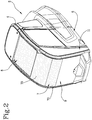
Figure 2 is a perspective view of a portion of the self-propelled operating machine ofFigure 1 ; -
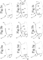
Figures 3a-3i schematically illustrate a plurality of possible embodiments of a portion of the self-propelled operating machine ofFigure 1 . - With reference to the accompanying drawings, the
numeral 1 denotes in its entirety a self-propelled operating machine made according to the invention. - Preferably, the machine according to the invention consists of a
telehandler 1, both fixed, rotary and articulated. - The
operating machine 1 comprises at least onecontrol cabin 2 and atelescopic operating arm 3 at the distal end of which is removably coupled an apparatus for lifting and moving a load. - The
cabin 2 comprises amounting frame 4 designed to delimit acab 5 for the operator. - The
control cabin 2 comprises adoor 6 giving access to thecab 5. - The
control cabin 2 comprises at least onetransparent wall 7 applied to the supportingframe 4 in such a way as to delimit thecab 5. - In particular, the
transparent wall 7 is configured to give the operator a large visibility in such a way as to increase the safety in the movement of the loads during the operating steps. - According to a possible embodiment and as illustrated in the accompanying drawings, the
control cabin 2 has at least oneupper wall 8, which acts as a roof, and afront wall 9, which acts as a windscreen, which may form a continuous single glazing. - More generally speaking, the
transparent wall 7 may be continuous and at least partly extend in theupper wall 8 and in the front wall 9 (as illustrated inFigure 3g ). - In accordance with that embodiment, the
control cabin 2 guarantees the operator a continuous view of the load being moved, for example during a movement along a vertical direction, preventing structural elements, for example portions of the supportingframe 4 joining thefront wall 9 and theupper wall 8, from being interposed between the operator and the load. - The
control cabin 2 may also have arear wall 10 and/or at least oneside wall 11 operatively connected to form thecab 5 for the operator. - In practice, the
control cabin 2 may comprise a plurality oftransparent walls 7 applied to the supportingframe 4 and delimiting thecab 5 for the operator. - The
transparent wall 7 may be made of composite glass (or layered glass) configured to guarantee a high level of safety inside thecabin 5 during the operating steps of theoperating machine 1. - According to an important aspect of the invention, the
transparent wall 7 of thecontrol cabin 2 can be made opaque in a controlled fashion. - In other words, the
control cabin 2 comprises at least onetransparent wall 7 whose opaqueness is adjustable in order to define a plurality of different operating conditions inside thecab 5. - In this way it is possible to limit the brightness level inside the
cab 5 reducing the risk of glare and, therefore, increasing the comfort for the operator during the operating steps of theoperating machine 1. - Moreover, the
transparent walls 7 which can be made opaque allow the luminosity inside the control cabin to be limited, guaranteeing at the same time a complete view of the operating unit for the operator. - In other words, the
transparent walls 7 which can be made opaque reduce the brightness inside the control cabin without the need to interpose external elements which would reduce the view of the operator. - According to a possible embodiment, the
transparent wall 7 houses internally a plurality of electrically reactive elements. The electrically reactive elements are configured to define an opaqueness of thetransparent wall 7 following electrical energising exerted by a power supply unit (not illustrated in the accompanying drawings). - In particular, the
transparent wall 7 may comprise a central layer interposed between a first and a second outer layer. - The first and second outer layers are configured to house the above-mentioned plurality of electrically reactive elements.
- Advantageously, the at least one
transparent wall 7 which can be made opaque may be positioned on thefront wall 9 and/or on theupper wall 8. - In that way, the
transparent wall 7 guarantees that the operator has continuous protection against the risk of glare caused by sunlight when theoperating unit 3 is moved. - According to a possible embodiment and as illustrated in
Figures 3a, 3b, 3c , thecontrol cabin 2 may comprise one or moretransparent walls 7 which are separate from each other and can be made opaque in a selective fashion. - Moreover, the
control cabin 2 may comprise at least onetransparent wall 7 divided into a plurality oftransparent portions 70 which can be made opaque in a selective fashion (Figures 3d, 3e, 3f ). - In other words, the
transparent wall 7 may have a plurality ofportions 70 which can be made opaque independently of each other in such a way as to obtain a sectorial opaqueness of thetransparent wall 7. - According to further possible embodiments and as illustrated in
Figures 3h, 3i , thecontrol cabin 2 may have one or moretransparent walls 7 which are separate from each other at least one of which is divided into a plurality oftransparent portions 70 which can be made opaque in a selective fashion. - Advantageously, the
transparent walls 7 and/or thetransparent portions 70 which can be made opaque in a selective fashion can be positioned in succession from thefront wall 9 towards theupper wall 8 to guarantee a high level of customisation of the operating conditions inside thecab 5. - According to a particular embodiment, the
operating machine 1 comprises a control unit (not illustrated in the accompanying drawings) configured for detecting and/or receiving at least one operating parameter of theoperating machine 1. - In particular, the control unit is configured to act on the
transparent wall 7 in such a way as to modify the degree of opaqueness, or also for modifying that of thetransparent portions 70, as a function of the operating parameter detected and/or received. - Advantageously, the above-mentioned operating parameter may comprise information correlated with the positioning of the load positioned on the
movement unit 3. - Moreover, the control unit may be configured to detect and/or receive information relating to the positioning of the sun.
- In this way, the control unit can modify the degree of opaqueness of the
transparent wall 7 and/or of thetransparent portions 70 to guarantee a high visibility for the operator, reducing the probability of glare. - The
operating machine 1 may comprise activation means (not illustrated in the accompanying drawings) which can be operated by the operator for activating and/or deactivating an opaqueness of thetransparent wall 7 and/or thetransparent portions 70. - Moreover, the
operating machine 1 may comprise adjustment means (not illustrated in the accompanying drawings) configured for setting up and/or varying a level of opaqueness of thetransparent wall 7 and/or of thetransparent portions 70. - In other words, the adjustment means make it possible to modify the degree of opaqueness of the
transparent wall 7 and/or of thetransparent portions 70 in such a way as to create a plurality of operating conditions inside thecab 5 designed to improve visibility and thus the comfort of the operator during the operating steps. - In particular, the adjustment means may define an adjustment of the opaqueness of the
transparent wall 7 and/or of thetransparent portions 70 according to a plurality of different and preset levels of opacity. - Moreover, the adjustment means can also provide continuous adjustment of the opaqueness of the
transparent wall 7 and of thetransparent portions 70. - Preferably, the adjustment means can allow an adjustment according to a plurality of different and preset levels of opacity and, alternatively, according to a continuous adjustment of the percentage of opacity.
- According to some possible embodiments, the activation and/or the adjustment means are operatively connected to the control unit in such a way as to allow both an autonomous and manual activation and/or adjustment of the opaqueness of the
transparent wall 7 and/or of thetransparent portions 70. - It should be noted, therefore, that the invention achieves the preset aims by providing a self-propelled operating machine having a control cabin which is able to increase the safety during the operations for moving loads and/or during the movement of the self-propelled operating machine thanks to the presence of at least one transparent wall which can be made opaque in a controlled fashion which improves the conditions of visibility and limits the risk of glare for the operator.
- In this way, moreover, the self-propelled operating machine contributes to increasing the comfort for the operator during the operating steps.
- Moreover, advantageously, the large transparent walls of the control cabin guarantee a continuous view of the load being moved by the operator, limiting the possibility that structural elements, for example portions of the supporting frame, are interposed between the operator and the load.
- Advantageously, the transparent walls and/or the transparent portions which can be made opaque in a selective fashion guarantee a high level of customisation of the conditions of visibility inside the cabin.
- Moreover, advantageously, the above-mentioned opaque walls and/or portions limit the entrance of the sun's rays which, for example during the summer, determine a considerable increase in the temperature inside the cab.
Claims (12)
- A self-propelled operating machine (1) comprising at least one control cabin (2) for housing an operator and a unit (3) for moving a load, wherein said control cabin (2) comprises a supporting frame (4) and at least one transparent wall (7) applied to said supporting frame (4) and delimiting at least partly the cabin (2), said transparent wall (7) being made opaque in a controlled fashion.
- The operating machine according to claim 1, wherein said control cabin (2) has at least one upper wall (8) and a front wall (9), the transparent wall (7) which can be made opaque being positioned on said front wall (9) and/or on said upper wall (8).
- The operating machine according to claim 1 or 2, comprising a plurality of transparent walls (7) which are separate from each other and can be made opaque in a selective fashion.
- The operating machine according to claim 1 or 2, comprising a transparent wall (7) divided into a plurality of transparent portions (70) which can be made opaque in a selective fashion.
- The operating machine according to claim 3 or 4, wherein said transparent walls (7) or transparent portions (70) which can be made opaque in a selective fashion are positioned in succession from the front wall (9) towards said upper wall (8).
- The operating machine according to claim 1 or 2, comprising a plurality of transparent walls (7) each divided into a plurality of transparent portions (70) which can be made opaque in a selective fashion, preferably said transparent walls (7) being positioned in succession from the front wall (9) towards said upper wall (8).
- The operating machine according to any one of the preceding claims, comprising activation means which can be operated by the operator for activating and/or deactivating the making opaque of the transparent wall (7).
- The operating machine according to any one of the preceding claims, comprising a control unit configured for detecting and/or receiving at least one operating parameter of the self-propelled operating machine (1) and for acting on the transparent wall (7) for modifying a degree of opaqueness as a function of said operating parameter detected and/or received.
- The operating machine according to any one of the preceding claims, comprising adjusting means configured for setting up and/or varying a level of opaqueness of the transparent wall (7).
- The operating machine according to any one of the preceding claims, wherein the transparent wall (7) is made of composite glass.
- The operating machine according to any one of the preceding claims, wherein the transparent wall (7) houses internally a plurality of electrically reactive elements, said electrically reactive elements being configured to define an opaqueness of the transparent wall (7) following electrical energising applied by a power supply unit.
- The operating machine according to claim 11, wherein the transparent wall (7) comprises a central layer interposed between a first and a second outer layer, said first and the second outer layer housing said plurality of electrically reactive elements.
Priority Applications (4)
| Application Number | Priority Date | Filing Date | Title |
|---|---|---|---|
| SM20250275T SMT202500275T1 (en) | 2019-12-10 | 2020-12-04 | Self-propelled operating machine equipped with an improved cabin |
| HRP20250840TT HRP20250840T1 (en) | 2019-12-10 | 2020-12-04 | SELF-PROPELLED WORKING MACHINE EQUIPPED WITH AN IMPROVED CABIN |
| SI202030642T SI3835252T1 (en) | 2019-12-10 | 2020-12-04 | Self-propelled operating machine equipped with an improved cabin |
| RS20250685A RS67001B1 (en) | 2019-12-10 | 2020-12-04 | Self-propelled operating machine equipped with an improved cabin |
Applications Claiming Priority (1)
| Application Number | Priority Date | Filing Date | Title |
|---|---|---|---|
| IT102019000023532A IT201900023532A1 (en) | 2019-12-10 | 2019-12-10 | Self-propelled operating machine equipped with an improved cabin |
Publications (2)
| Publication Number | Publication Date |
|---|---|
| EP3835252A1 true EP3835252A1 (en) | 2021-06-16 |
| EP3835252B1 EP3835252B1 (en) | 2025-04-30 |
Family
ID=70154973
Family Applications (1)
| Application Number | Title | Priority Date | Filing Date |
|---|---|---|---|
| EP20212043.2A Active EP3835252B1 (en) | 2019-12-10 | 2020-12-04 | Self-propelled operating machine equipped with an improved cabin |
Country Status (18)
| Country | Link |
|---|---|
| US (1) | US11724575B2 (en) |
| EP (1) | EP3835252B1 (en) |
| CN (1) | CN112938822A (en) |
| AU (1) | AU2020277239B2 (en) |
| CA (1) | CA3100456A1 (en) |
| DK (1) | DK3835252T3 (en) |
| ES (1) | ES3034962T3 (en) |
| FI (1) | FI3835252T3 (en) |
| HR (1) | HRP20250840T1 (en) |
| HU (1) | HUE072640T2 (en) |
| IT (1) | IT201900023532A1 (en) |
| LT (1) | LT3835252T (en) |
| PL (1) | PL3835252T3 (en) |
| PT (1) | PT3835252T (en) |
| RS (1) | RS67001B1 (en) |
| SI (1) | SI3835252T1 (en) |
| SM (1) | SMT202500275T1 (en) |
| ZA (1) | ZA202007339B (en) |
Citations (5)
| Publication number | Priority date | Publication date | Assignee | Title |
|---|---|---|---|---|
| JP2003276436A (en) * | 2002-03-26 | 2003-09-30 | Sumitomo (Shi) Construction Machinery Manufacturing Co Ltd | Light shielding device for roof window of cab of construction machinery |
| US20160052374A1 (en) * | 2014-08-25 | 2016-02-25 | Claas Selbstfahrende Erntemaschinen Gmbh | Agricultural vehicle comprising a cab window having changeable transparency |
| JP2016175424A (en) * | 2015-03-18 | 2016-10-06 | 株式会社豊田自動織機 | Industrial vehicle |
| US20180204538A1 (en) * | 2017-01-13 | 2018-07-19 | Continental Automotive Systems, Inc. | External light dimming system and method |
| CN110370898A (en) * | 2019-08-29 | 2019-10-25 | 三一重机有限公司 | Vehicle window, cockpit and excavator |
Family Cites Families (11)
| Publication number | Priority date | Publication date | Assignee | Title |
|---|---|---|---|---|
| EP0436283A3 (en) * | 1989-12-20 | 1991-11-27 | Asc Incorporated | Retracting sunroof system with variable opacity |
| ATE494172T1 (en) * | 2004-02-23 | 2011-01-15 | Volkswagen Ag | MOTOR VEHICLE WITH A WINDOW PANEL WITH ADJUSTABLE TRANSPARENCY |
| US20090058126A1 (en) * | 2007-09-05 | 2009-03-05 | Craig Broude | Glare reduction |
| EP2628617B1 (en) * | 2012-02-20 | 2019-04-03 | Yachiyo Industry Co., Ltd. | Mounting structure for film-shaped electric device |
| US9365161B2 (en) * | 2014-06-19 | 2016-06-14 | Mario Arturo Mannheim Astete | Panoramic extended windshield with integrated non-moving blind |
| DE102015014647A1 (en) * | 2015-11-12 | 2017-08-31 | GM Global Technology Operations LLC (n. d. Gesetzen des Staates Delaware) | Window pane for a motor vehicle |
| ITUB20159622A1 (en) * | 2015-12-28 | 2017-06-28 | Manitou Italia Srl | SELF PROPELLED MACHINE |
| MA53958A (en) * | 2018-10-26 | 2022-02-09 | Saint Gobain | LAMINATED GLASS WITH A FUNCTIONAL ELEMENT SWITCHABLE BY SEGMENTS AND WITH OPTICAL PROPERTIES SUITABLE FOR ELECTRICAL CONTROL |
| JP6844603B2 (en) * | 2018-11-28 | 2021-03-17 | ダイキン工業株式会社 | Traffic mobiles and automobiles |
| DE102019129399A1 (en) * | 2019-10-31 | 2021-05-06 | Dr. Ing. H.C. F. Porsche Aktiengesellschaft | Window device for a motor vehicle and method for operating it |
| DE102020118885A1 (en) * | 2020-07-16 | 2022-01-20 | Konecranes Global Corporation | Crane with improved glare protection for its operator and method of using the improved glare protection |
-
2019
- 2019-12-10 IT IT102019000023532A patent/IT201900023532A1/en unknown
-
2020
- 2020-11-24 CA CA3100456A patent/CA3100456A1/en active Pending
- 2020-11-25 ZA ZA2020/07339A patent/ZA202007339B/en unknown
- 2020-11-26 AU AU2020277239A patent/AU2020277239B2/en active Active
- 2020-12-02 US US17/109,721 patent/US11724575B2/en active Active
- 2020-12-04 SM SM20250275T patent/SMT202500275T1/en unknown
- 2020-12-04 PL PL20212043.2T patent/PL3835252T3/en unknown
- 2020-12-04 SI SI202030642T patent/SI3835252T1/en unknown
- 2020-12-04 LT LTEP20212043.2T patent/LT3835252T/en unknown
- 2020-12-04 EP EP20212043.2A patent/EP3835252B1/en active Active
- 2020-12-04 PT PT202120432T patent/PT3835252T/en unknown
- 2020-12-04 RS RS20250685A patent/RS67001B1/en unknown
- 2020-12-04 HU HUE20212043A patent/HUE072640T2/en unknown
- 2020-12-04 FI FIEP20212043.2T patent/FI3835252T3/en active
- 2020-12-04 ES ES20212043T patent/ES3034962T3/en active Active
- 2020-12-04 HR HRP20250840TT patent/HRP20250840T1/en unknown
- 2020-12-04 DK DK20212043.2T patent/DK3835252T3/en active
- 2020-12-08 CN CN202011426589.3A patent/CN112938822A/en active Pending
Patent Citations (5)
| Publication number | Priority date | Publication date | Assignee | Title |
|---|---|---|---|---|
| JP2003276436A (en) * | 2002-03-26 | 2003-09-30 | Sumitomo (Shi) Construction Machinery Manufacturing Co Ltd | Light shielding device for roof window of cab of construction machinery |
| US20160052374A1 (en) * | 2014-08-25 | 2016-02-25 | Claas Selbstfahrende Erntemaschinen Gmbh | Agricultural vehicle comprising a cab window having changeable transparency |
| JP2016175424A (en) * | 2015-03-18 | 2016-10-06 | 株式会社豊田自動織機 | Industrial vehicle |
| US20180204538A1 (en) * | 2017-01-13 | 2018-07-19 | Continental Automotive Systems, Inc. | External light dimming system and method |
| CN110370898A (en) * | 2019-08-29 | 2019-10-25 | 三一重机有限公司 | Vehicle window, cockpit and excavator |
Also Published As
| Publication number | Publication date |
|---|---|
| SI3835252T1 (en) | 2025-10-30 |
| DK3835252T3 (en) | 2025-07-14 |
| IT201900023532A1 (en) | 2021-06-10 |
| LT3835252T (en) | 2025-08-11 |
| HRP20250840T1 (en) | 2025-09-12 |
| ES3034962T3 (en) | 2025-08-27 |
| PL3835252T3 (en) | 2025-08-18 |
| US11724575B2 (en) | 2023-08-15 |
| ZA202007339B (en) | 2021-10-27 |
| CA3100456A1 (en) | 2021-06-10 |
| RS67001B1 (en) | 2025-08-29 |
| SMT202500275T1 (en) | 2025-09-12 |
| CN112938822A (en) | 2021-06-11 |
| US20210170838A1 (en) | 2021-06-10 |
| HUE072640T2 (en) | 2025-11-28 |
| EP3835252B1 (en) | 2025-04-30 |
| AU2020277239A1 (en) | 2021-06-24 |
| AU2020277239B2 (en) | 2026-02-19 |
| PT3835252T (en) | 2025-07-11 |
| FI3835252T3 (en) | 2025-07-10 |
Similar Documents
| Publication | Publication Date | Title |
|---|---|---|
| US9908389B2 (en) | Agricultural vehicle comprising a cab window having changeable transparency | |
| CN108928393B (en) | Vehicle glass roof systems | |
| EP3486209B1 (en) | Industrial truck with transparent display within driver protection roof | |
| AU2020277239B2 (en) | Self-propelled operating machine equipped with an improved cabin | |
| US20090018709A1 (en) | Operator Control System for a Vehicle | |
| RU2808767C2 (en) | Self-propelled working machine with improved cabin | |
| WO2012156779A1 (en) | A window darkening system and method for vehicles | |
| EP2511225B1 (en) | Industrial truck, in particular high-picking truck | |
| US20110043922A1 (en) | Vehicle Pane and Motor Vehicle Having a Vehicle Pane | |
| CN108928458A (en) | Windshield system for aircraft cockpit | |
| CN113665323A (en) | Sunshade device, automobile and adjustment method of sunshade device | |
| EP2261107B1 (en) | Work machine cab | |
| CN210309858U (en) | Windows, Cockpits and Excavators | |
| DE102020118885A1 (en) | Crane with improved glare protection for its operator and method of using the improved glare protection | |
| JP2016175424A (en) | Industrial vehicle | |
| DE102014012399B4 (en) | Method for controlling and adjusting a glare protection device of a vehicle | |
| DE102017214626A1 (en) | Windscreen with sun visor | |
| DE102011100030A1 (en) | Industrial truck has lighting device, which is arranged at outer side of vehicle, and is switched off or shitched on by function of steering angle of steering device | |
| CN222989610U (en) | Door machine cab convenient for operation | |
| KR200211117Y1 (en) | Shading system of vehicle | |
| CN209921009U (en) | Sun-shading device and vehicle | |
| EP4624208A1 (en) | Work machine | |
| CN113147331B (en) | A windshield for a vehicle and its control method and vehicle | |
| JPH01182121A (en) | Automotive auto-sunvisor | |
| CN210212297U (en) | Intelligent cab assembly for port machinery |
Legal Events
| Date | Code | Title | Description |
|---|---|---|---|
| REG | Reference to a national code |
Ref country code: HR Ref legal event code: TUEP Ref document number: P20250840T Country of ref document: HR |
|
| PUAI | Public reference made under article 153(3) epc to a published international application that has entered the european phase |
Free format text: ORIGINAL CODE: 0009012 |
|
| STAA | Information on the status of an ep patent application or granted ep patent |
Free format text: STATUS: THE APPLICATION HAS BEEN PUBLISHED |
|
| AK | Designated contracting states |
Kind code of ref document: A1 Designated state(s): AL AT BE BG CH CY CZ DE DK EE ES FI FR GB GR HR HU IE IS IT LI LT LU LV MC MK MT NL NO PL PT RO RS SE SI SK SM TR |
|
| STAA | Information on the status of an ep patent application or granted ep patent |
Free format text: STATUS: REQUEST FOR EXAMINATION WAS MADE |
|
| 17P | Request for examination filed |
Effective date: 20211213 |
|
| RBV | Designated contracting states (corrected) |
Designated state(s): AL AT BE BG CH CY CZ DE DK EE ES FI FR GB GR HR HU IE IS IT LI LT LU LV MC MK MT NL NO PL PT RO RS SE SI SK SM TR |
|
| P01 | Opt-out of the competence of the unified patent court (upc) registered |
Effective date: 20230614 |
|
| STAA | Information on the status of an ep patent application or granted ep patent |
Free format text: STATUS: EXAMINATION IS IN PROGRESS |
|
| 17Q | First examination report despatched |
Effective date: 20240613 |
|
| 17Q | First examination report despatched |
Effective date: 20240626 |
|
| GRAP | Despatch of communication of intention to grant a patent |
Free format text: ORIGINAL CODE: EPIDOSNIGR1 |
|
| STAA | Information on the status of an ep patent application or granted ep patent |
Free format text: STATUS: GRANT OF PATENT IS INTENDED |
|
| INTG | Intention to grant announced |
Effective date: 20241204 |
|
| GRAS | Grant fee paid |
Free format text: ORIGINAL CODE: EPIDOSNIGR3 |
|
| GRAA | (expected) grant |
Free format text: ORIGINAL CODE: 0009210 |
|
| STAA | Information on the status of an ep patent application or granted ep patent |
Free format text: STATUS: THE PATENT HAS BEEN GRANTED |
|
| AK | Designated contracting states |
Kind code of ref document: B1 Designated state(s): AL AT BE BG CH CY CZ DE DK EE ES FI FR GB GR HR HU IE IS IT LI LT LU LV MC MK MT NL NO PL PT RO RS SE SI SK SM TR |
|
| REG | Reference to a national code |
Ref country code: CH Ref legal event code: EP Ref country code: GB Ref legal event code: FG4D |
|
| REG | Reference to a national code |
Ref country code: IE Ref legal event code: FG4D |
|
| REG | Reference to a national code |
Ref country code: DE Ref legal event code: R096 Ref document number: 602020050336 Country of ref document: DE |
|
| REG | Reference to a national code |
Ref country code: FI Ref legal event code: FGE |
|
| REG | Reference to a national code |
Ref country code: PT Ref legal event code: SC4A Ref document number: 3835252 Country of ref document: PT Date of ref document: 20250711 Kind code of ref document: T Free format text: AVAILABILITY OF NATIONAL TRANSLATION Effective date: 20250707 |
|
| REG | Reference to a national code |
Ref country code: DK Ref legal event code: T3 Effective date: 20250704 |
|
| REG | Reference to a national code |
Ref country code: NL Ref legal event code: FP |
|
| REG | Reference to a national code |
Ref country code: SE Ref legal event code: TRGR |
|
| REG | Reference to a national code |
Ref country code: GR Ref legal event code: EP Ref document number: 20250401483 Country of ref document: GR Effective date: 20250808 Ref country code: ES Ref legal event code: FG2A Ref document number: 3034962 Country of ref document: ES Kind code of ref document: T3 Effective date: 20250827 |
|
| REG | Reference to a national code |
Ref country code: SK Ref legal event code: T3 Ref document number: E 46767 Country of ref document: SK |
|
| REG | Reference to a national code |
Ref country code: HR Ref legal event code: T1PR Ref document number: P20250840 Country of ref document: HR |
|
| REG | Reference to a national code |
Ref country code: EE Ref legal event code: FG4A Ref document number: E025194 Country of ref document: EE Effective date: 20250710 |
|
| PG25 | Lapsed in a contracting state [announced via postgrant information from national office to epo] |
Ref country code: IS Free format text: LAPSE BECAUSE OF FAILURE TO SUBMIT A TRANSLATION OF THE DESCRIPTION OR TO PAY THE FEE WITHIN THE PRESCRIBED TIME-LIMIT Effective date: 20250830 |
|
| REG | Reference to a national code |
Ref country code: HU Ref legal event code: AG4A Ref document number: E072640 Country of ref document: HU |
|
| PGFP | Annual fee paid to national office [announced via postgrant information from national office to epo] |
Ref country code: PT Payment date: 20251121 Year of fee payment: 6 |
|
| REG | Reference to a national code |
Ref country code: HR Ref legal event code: ODRP Ref document number: P20250840 Country of ref document: HR Payment date: 20251124 Year of fee payment: 6 |
|
| REG | Reference to a national code |
Ref country code: CH Ref legal event code: U11 Free format text: ST27 STATUS EVENT CODE: U-0-0-U10-U11 (AS PROVIDED BY THE NATIONAL OFFICE) Effective date: 20260101 |
|
| PGFP | Annual fee paid to national office [announced via postgrant information from national office to epo] |
Ref country code: IS Payment date: 20251229 Year of fee payment: 6 |
|
| PGFP | Annual fee paid to national office [announced via postgrant information from national office to epo] |
Ref country code: LT Payment date: 20251124 Year of fee payment: 6 Ref country code: GB Payment date: 20251223 Year of fee payment: 6 |
|
| PGFP | Annual fee paid to national office [announced via postgrant information from national office to epo] |
Ref country code: MC Payment date: 20251219 Year of fee payment: 6 Ref country code: NO Payment date: 20251218 Year of fee payment: 6 |
|
| PGFP | Annual fee paid to national office [announced via postgrant information from national office to epo] |
Ref country code: AT Payment date: 20251218 Year of fee payment: 6 Ref country code: SM Payment date: 20251201 Year of fee payment: 6 Ref country code: MK Payment date: 20251125 Year of fee payment: 6 |
|
| PGFP | Annual fee paid to national office [announced via postgrant information from national office to epo] |
Ref country code: IT Payment date: 20251222 Year of fee payment: 6 Ref country code: FI Payment date: 20251222 Year of fee payment: 6 Ref country code: DK Payment date: 20251222 Year of fee payment: 6 |
|
| PGFP | Annual fee paid to national office [announced via postgrant information from national office to epo] |
Ref country code: LU Payment date: 20251222 Year of fee payment: 6 Ref country code: HR Payment date: 20251124 Year of fee payment: 6 Ref country code: HU Payment date: 20251203 Year of fee payment: 6 Ref country code: NL Payment date: 20251222 Year of fee payment: 6 Ref country code: FR Payment date: 20251223 Year of fee payment: 6 |
|
| PGFP | Annual fee paid to national office [announced via postgrant information from national office to epo] |
Ref country code: TR Payment date: 20251121 Year of fee payment: 6 Ref country code: AL Payment date: 20251230 Year of fee payment: 6 Ref country code: GR Payment date: 20251218 Year of fee payment: 6 |
|
| PGFP | Annual fee paid to national office [announced via postgrant information from national office to epo] |
Ref country code: SE Payment date: 20251222 Year of fee payment: 6 |
|
| PGFP | Annual fee paid to national office [announced via postgrant information from national office to epo] |
Ref country code: IE Payment date: 20251218 Year of fee payment: 6 Ref country code: CZ Payment date: 20251126 Year of fee payment: 6 Ref country code: CY Payment date: 20251127 Year of fee payment: 6 |
|
| PGFP | Annual fee paid to national office [announced via postgrant information from national office to epo] |
Ref country code: MT Payment date: 20251226 Year of fee payment: 6 Ref country code: LV Payment date: 20251219 Year of fee payment: 6 |
|
| PGFP | Annual fee paid to national office [announced via postgrant information from national office to epo] |
Ref country code: BG Payment date: 20251223 Year of fee payment: 6 Ref country code: PL Payment date: 20251125 Year of fee payment: 6 |
|
| PGFP | Annual fee paid to national office [announced via postgrant information from national office to epo] |
Ref country code: EE Payment date: 20251230 Year of fee payment: 6 |
|
| PGFP | Annual fee paid to national office [announced via postgrant information from national office to epo] |
Ref country code: SK Payment date: 20251124 Year of fee payment: 6 Ref country code: RO Payment date: 20251202 Year of fee payment: 6 |
|
| PGFP | Annual fee paid to national office [announced via postgrant information from national office to epo] |
Ref country code: RS Payment date: 20251121 Year of fee payment: 6 |
|
| PGFP | Annual fee paid to national office [announced via postgrant information from national office to epo] |
Ref country code: SI Payment date: 20251124 Year of fee payment: 6 |
|
| REG | Reference to a national code |
Ref country code: DE Ref legal event code: R097 Ref document number: 602020050336 Country of ref document: DE |
|
| PLBE | No opposition filed within time limit |
Free format text: ORIGINAL CODE: 0009261 |
|
| STAA | Information on the status of an ep patent application or granted ep patent |
Free format text: STATUS: NO OPPOSITION FILED WITHIN TIME LIMIT |
|
| REG | Reference to a national code |
Ref country code: CH Ref legal event code: L10 Free format text: ST27 STATUS EVENT CODE: U-0-0-L10-L00 (AS PROVIDED BY THE NATIONAL OFFICE) Effective date: 20260311 |
|
| 26N | No opposition filed |
Effective date: 20260202 |
|
| PGFP | Annual fee paid to national office [announced via postgrant information from national office to epo] |
Ref country code: ES Payment date: 20260122 Year of fee payment: 6 |
|
| PGFP | Annual fee paid to national office [announced via postgrant information from national office to epo] |
Ref country code: DE Payment date: 20251229 Year of fee payment: 6 |
|
| PGFP | Annual fee paid to national office [announced via postgrant information from national office to epo] |
Ref country code: BE Payment date: 20260109 Year of fee payment: 6 |
|
| PGFP | Annual fee paid to national office [announced via postgrant information from national office to epo] |
Ref country code: CH Payment date: 20260101 Year of fee payment: 6 |