EP3835200A1 - Überwachungssystem für eine anordnung mit kinematischer kopplung - Google Patents
Überwachungssystem für eine anordnung mit kinematischer kopplung Download PDFInfo
- Publication number
- EP3835200A1 EP3835200A1 EP20212918.5A EP20212918A EP3835200A1 EP 3835200 A1 EP3835200 A1 EP 3835200A1 EP 20212918 A EP20212918 A EP 20212918A EP 3835200 A1 EP3835200 A1 EP 3835200A1
- Authority
- EP
- European Patent Office
- Prior art keywords
- movement
- sensor
- actuator
- controlled element
- aircraft
- Prior art date
- Legal status (The legal status is an assumption and is not a legal conclusion. Google has not performed a legal analysis and makes no representation as to the accuracy of the status listed.)
- Granted
Links
Images
Classifications
-
- B—PERFORMING OPERATIONS; TRANSPORTING
- B64—AIRCRAFT; AVIATION; COSMONAUTICS
- B64C—AEROPLANES; HELICOPTERS
- B64C13/00—Control systems or transmitting systems for actuating flying-control surfaces, lift-increasing flaps, air brakes, or spoilers
- B64C13/24—Transmitting means
- B64C13/26—Transmitting means without power amplification or where power amplification is irrelevant
- B64C13/28—Transmitting means without power amplification or where power amplification is irrelevant mechanical
-
- B—PERFORMING OPERATIONS; TRANSPORTING
- B64—AIRCRAFT; AVIATION; COSMONAUTICS
- B64F—GROUND OR AIRCRAFT-CARRIER-DECK INSTALLATIONS SPECIALLY ADAPTED FOR USE IN CONNECTION WITH AIRCRAFT; DESIGNING, MANUFACTURING, ASSEMBLING, CLEANING, MAINTAINING OR REPAIRING AIRCRAFT, NOT OTHERWISE PROVIDED FOR; HANDLING, TRANSPORTING, TESTING OR INSPECTING AIRCRAFT COMPONENTS, NOT OTHERWISE PROVIDED FOR
- B64F5/00—Designing, manufacturing, assembling, cleaning, maintaining or repairing aircraft, not otherwise provided for; Handling, transporting, testing or inspecting aircraft components, not otherwise provided for
- B64F5/60—Testing or inspecting aircraft components or systems
-
- B—PERFORMING OPERATIONS; TRANSPORTING
- B64—AIRCRAFT; AVIATION; COSMONAUTICS
- B64C—AEROPLANES; HELICOPTERS
- B64C13/00—Control systems or transmitting systems for actuating flying-control surfaces, lift-increasing flaps, air brakes, or spoilers
- B64C13/02—Initiating means
- B64C13/16—Initiating means actuated automatically, e.g. responsive to gust detectors
- B64C13/18—Initiating means actuated automatically, e.g. responsive to gust detectors using automatic pilot
-
- B—PERFORMING OPERATIONS; TRANSPORTING
- B64—AIRCRAFT; AVIATION; COSMONAUTICS
- B64D—EQUIPMENT FOR FITTING IN OR TO AIRCRAFT; FLIGHT SUITS; PARACHUTES; ARRANGEMENT OR MOUNTING OF POWER PLANTS OR PROPULSION TRANSMISSIONS IN AIRCRAFT
- B64D45/00—Aircraft indicators or protectors not otherwise provided for
- B64D45/0005—Devices specially adapted to indicate the position of a movable element of the aircraft, e.g. landing gear
-
- G—PHYSICS
- G01—MEASURING; TESTING
- G01B—MEASURING LENGTH, THICKNESS OR SIMILAR LINEAR DIMENSIONS; MEASURING ANGLES; MEASURING AREAS; MEASURING IRREGULARITIES OF SURFACES OR CONTOURS
- G01B21/00—Measuring arrangements or details thereof, where the measuring technique is not covered by the other groups of this subclass, unspecified or not relevant
- G01B21/22—Measuring arrangements or details thereof, where the measuring technique is not covered by the other groups of this subclass, unspecified or not relevant for measuring angles or tapers; for testing the alignment of axes
-
- B—PERFORMING OPERATIONS; TRANSPORTING
- B64—AIRCRAFT; AVIATION; COSMONAUTICS
- B64D—EQUIPMENT FOR FITTING IN OR TO AIRCRAFT; FLIGHT SUITS; PARACHUTES; ARRANGEMENT OR MOUNTING OF POWER PLANTS OR PROPULSION TRANSMISSIONS IN AIRCRAFT
- B64D45/00—Aircraft indicators or protectors not otherwise provided for
- B64D2045/0085—Devices for aircraft health monitoring, e.g. monitoring flutter or vibration
Definitions
- the description relates to a system for monitoring the quality of a kinematic coupling between an actuator and an element controlled by the actuator.
- the description therefore relates to a monitoring system for a kinematic coupling.
- the description relates to safety-relevant systems with such a monitoring system, in particular an aircraft with a monitoring system.
- Kinematic couplings are used in a large number of technical systems in order to transfer movement from an input side to an output side.
- An actuator or a drive is typically arranged on the input side, whereas a controlled or moved element is arranged on the output side.
- the actuator generates a movement and a kinematic coupling transmits this movement to the controlled element.
- wear at any of the above-mentioned points can result in a movement of the actuator on the input side no longer correlating directly with a movement of the controlled element on the output side or in that the controlled element moves when external forces act on the controlled element without that the actuator moves on the input side.
- this state of the system which consists of an actuator, kinematic coupling and controlled element, it can be said that the system has play.
- a monitoring system for monitoring a kinematic coupling between an actuator and a controlled element.
- the monitoring system has a first sensor, a second sensor, and a computing unit.
- the first sensor is arranged so that it detects an effective movement of the actuator and based on the detected active movement of the actuator provides a first signal.
- the second sensor is arranged to detect a movement of the controlled element and to provide a second signal based on the detected movement of the controlled element.
- the computing unit is connected to the first sensor and the second sensor and is designed to receive the first signal and the second signal.
- the computing unit is further designed to determine an expected movement of the controlled element based on the first signal and to compare the expected movement with the detected movement corresponding to the second signal and to provide a deviation between the expected movement and the detected movement.
- a kinematic system typically consists of a drive (actuator), a kinematic coupling and a controlled element.
- the kinematic coupling is connected to the actuator and the controlled element in such a way that a movement of the actuator is transmitted to the controlled element.
- the movement of the actuator can be transmitted to the controlled element via the kinematic coupling with or without translation.
- the actuator can be connected to the kinematic coupling, for example by means of rods, levers and joints or hinges, in order to transfer forces, e.g. tensile and / or compressive forces, to the kinematic coupling.
- the kinematic coupling is, for example, also connected to the controlled element by means of rods, levers and joints or hinges in order to transfer forces, e.g. tensile and / or compressive forces, to the controlled element.
- the kinematic coupling can transmit a translational or rotational movement from the actuator to the controlled element.
- the kinematic coupling can have various elements in order to carry out the transmission to accomplish the movement, namely: rods, levers, joints, ropes, rollers, gears or the like.
- the monitoring system described herein can advantageously be used where a movement of the actuator has to correlate to a very high degree and with a high degree of accuracy with a movement of the controlled element and play which results from one of the components of the kinematic system is highly undesirable.
- play can be greatly reduced or even eliminated in the actuator as such.
- hydraulic actuators are characterized by little or no risk of backlash.
- the controlled element can be designed in such a way that play is reduced or virtually eliminated.
- the main source of backlash in a kinematic system essentially remains the kinematic coupling.
- the monitoring system described herein is suitable for identifying play in a kinematic system regardless of where that play is introduced into the system.
- the monitoring system is based on the fact that the movement of the controlled element is additionally and separately detected by the second sensor. This actual movement or sensed movement of the controlled element is compared to an expected movement of the controlled element, the expected movement of the controlled element being determined based on the movement of the actuator. In other words, the movement of the controlled element is determined in two ways: on the one hand as an expected movement based on the movement of the actuator and, in addition, as a direct detection of its actual movement by means of the second sensor.
- the computing unit uses a starting position and / or a change in position of an actuating element of the actuator.
- the adjusting element of the actuator represents the Interface of the actuator to the kinematic coupling and can be designed, for example, as a rod for transmitting tensile and compressive forces or as a rope for transmitting tensile forces.
- the first sensor is arranged on the actuator or on the actuator of the actuator or on the surroundings of the actuator in order to determine a movement transmitted to the kinematic coupling and to convert it into a measurement signal, that is, the first signal.
- the first signal accordingly indicates a position or a change in the position of the actuating element of the actuator.
- the second sensor is coupled to the controlled element or to an environment of the controlled element, so that the movement of the controlled element can be detected. It also applies to the second sensor that the detected movement is converted into a measurement signal, this measurement signal being referred to as the second signal.
- the second sensor can for example be arranged on the controlled element. When the controlled element moves, the second sensor can detect this movement on the basis of its changed position or orientation in relation to the environment.
- the second sensor can also be arranged at a point in the vicinity of the controlled element, so that the controlled element moves with respect to the second sensor. In any case, the second signal serves to indicate the actual movement of the controlled element.
- Deviations between the expected and the detected movement occur in particular when a system component such as the kinematic coupling has mechanical play. It is also possible, if the kinematic coupling has play, for the controlled element to move under the influence of external forces without this movement being specified or initiated by the actuator. This case also represents a discrepancy between the expected and the detected movement. The discrepancy can be determined as the difference between the two signals.
- the expected Movement is zero because the actuator has not specified any movement, whereas the detected movement represents an actual movement of the controlled element.
- the actuator can be a hydraulic element, a mechanical drive or an electro-mechanical drive.
- the actuator is designed, for example, to receive a command signal and to generate an effective movement corresponding to the command signal. Provided that there is a direct relationship between the command signal and the active movement, it is also conceivable that the command signal is used for the comparison with the detected movement of the controlled element.
- the monitored system is subject to continuous monitoring during its operating time.
- Permanent monitoring means that the expected movement of the controlled element based on the active movement of the actuator is repeatedly compared at regular or irregular time intervals with the actual movement of the controlled element and in the event of deviations (difference between expected and actual movement or between the corresponding Signals) a corresponding message is provided. This is particularly helpful in safety-critical applications because the backlash in a kinematic system is not only monitored at the scheduled maintenance intervals, but also continuously. This can be particularly helpful where a game can lead to rapid and severe wear and tear of the system or even to its destruction due to high external forces.
- the computing unit is designed to compare the discrepancy between the expected movement and the detected movement with a threshold value and to output an error message if the discrepancy reaches or exceeds the threshold value.
- the amount of the deviation between the expected movement and the detected movement is compared with the threshold value.
- the information alone that there is a deviation is sufficient, whereas the direction of the deviation (positive or negative) is initially irrelevant.
- the deviation can then be examined more closely in subsequent measuring and checking steps.
- the threshold value for the deviation can be specified as an angle. In safety-critical environments, this threshold value can be very low, for example a few millirad (mrad). However, it is just as conceivable that the threshold value is defined as the absolute deflection (millimeters or centimeters) by which the actual movement deviates from the expected movement at a point on the controlled element.
- the computing unit is designed to determine the expected movement of the controlled element based on a model of the kinematic coupling.
- the monitoring system can be used in an aircraft to check or monitor the movement of control surfaces based on movements of actuators.
- There is a model of the aircraft which is used by a controller or the computing unit in order to calculate the reaction of controlled elements to an input (ie the command signal transmitted to the actuator). If, for example, an actuator that functions as an actuator of a control surface is actuated, the model of the aircraft can be used to calculate how the control surface reacts to an input to the actuator. This calculation corresponds to the expected movement of the controlled element, ie the control surface.
- the model can refer to the kinematic coupling between the actuator and the controlled element refer, but can also be a model of a higher-level arrangement which contains the actuator, the controlled element, and the kinematic coupling between the actuator and the controlled element.
- both the first sensor and the second sensor are selected from the group comprising: a motion sensor, a rotation rate sensor, a rotational position sensor, an angle sensor, a linear variable differential transformer, an optical sensor, a mechanical sensor moving parts, a magnetic sensor, a Hall-effect sensor.
- any sensor can be used which is suitable and designed to detect a translational or rotary movement of the actuating element of the actuator and / or of the controlled element and to generate and provide a signal corresponding to the detected movement.
- the second sensor is designed to detect the movement of the controlled element with a sampling rate of more than 1 kHz.
- the monitoring system is therefore designed to detect rapid and high-frequency movements and / or vibrations of the controlled element, such as those that occur, for example, when a control surface on an aircraft vibrates under the influence of the air flow acting on it, when the kinematics moving the control surface or holding it in a position has play.
- Both the second sensor and the computing unit must be designed to perform the sampling rate of several kHz (1 kHz up to several 10 kHz) and to be able to process the resulting data.
- the computing unit is designed to feed the second signal to a filter and to use the filtered signal for the comparison with the first signal.
- Load and movement peaks can thus be filtered out from the second signal, which may result from a high external force limited in time, but cannot be assigned to a game in the kinematics.
- the controlled element can move simply due to elastic deformation, even without the actuator moving.
- a low-pass filter for example, a low-pass filter, a Kalman filter, a Wiener filter or a correlation algorithm can be used as the filter.
- a filter is preferably designed as a digital filter algorithm and can be implemented in the computing unit as a separate filter module.
- an aircraft which has a monitoring system according to one or more embodiments of the monitoring system described herein.
- the monitoring system can be used in particular in security-relevant environments. These can be aircraft. However, other areas of application with high safety requirements and associated requirements for the accuracy and the functioning of a kinematic coupling between an actuator and an element controlled by it are also possible.
- the monitoring system can be used in industrial plants or watercraft.
- the monitoring system can be used, for example, in connection with locks or valves, the expected opening of which corresponds to the actual opening is compared. This can be done in the context of watercraft Monitoring systems can be used in a manner similar to aircraft, namely to monitor movable elements that are exposed to the flow of water (or the flow of air) and can be moved by an actuator.
- the aircraft can be aircraft, helicopters, or drones.
- the monitoring system can be used to compare an expected movement of an element exposed to the air flow with an actual movement of this element.
- the controlled element is a control surface of the aircraft and the actuator is an actuator connected to the control surface via a kinematic coupling.
- the actuator can be a hydraulic, mechanical or electromechanical element which is able to execute a movement so that this movement can be transmitted to the control surface via the kinematics and causes the control surface to move.
- the control surface can be, for example, a rudder or a flap of an aircraft, e.g. an elevator, aileron, rudder, canard, a trim tab that is assigned to one of these rudders, or a landing flap.
- the monitoring system can be used to monitor any moving elements in an aircraft (and / or other safety-related systems) and to correlate their actual movement with the requested movement (ie the target movement which, under normal conditions, corresponds to the movement of the actuator) compare and issue a message in the event of a discrepancy.
- the second sensor is arranged to a relative movement between the control surface and a To detect fuselage or another component of the aircraft connected to the fuselage.
- control surface is a rudder, in particular the relative movement between rudder and wing (aileron or flap relative to wing, elevator relative to elevator, rudder relative to fin) is recorded. If the control surface is a trim tab attached to a rudder, in particular the relative movement between the trim tab and the associated rudder can be detected.
- the second sensor is designed in particular to detect a pivoting movement of the control surface.
- the second sensor is designed, for example, as an angle sensor that detects a pivoting movement about a joint of the control surface, or as a deflection sensor that detects an absolute deflection of the control surface.
- the second sensor is attached in such a way that it can detect a movement of the control surface relative to its surroundings (trunk, fin, wing) or in a joint with which the control surface is attached to its surroundings.
- the computing unit implements flight control functions for the aircraft.
- the computing unit can be a computer which carries out functions of controlling the aircraft.
- This computer can, for its part, carry out the functionality of the computing unit described herein.
- the computer can also take on other functions of aircraft control.
- This alternative has the advantage that the monitoring system can be retrofitted in an existing aircraft without interfering with the existing systems must become. Only the existing control signal to the actuator or the measured value of the sensor assigned to the actuator has to be tapped.
- a task which is usually carried out at predetermined maintenance intervals on the ground by a separate test device is partially relocated to an aircraft and carried out in the aircraft during operation, i.e. in the air.
- the monitoring system continuously compares the expected movement of a control surface with the actual movement of this control surface and is able to output an indication of this deviation in the event of a deviation that exceeds a threshold value. The aircraft can then be subjected to a detailed check.
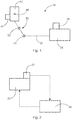
- Fig. 1 Fig. 10 shows a monitoring system 10 for a kinematic system.
- the kinematic system consists of an actuator 20, a kinematic coupling 30 and a controlled element 40.
- the actuator 20 is connected to an actuating element 22 via a joint 23 with the kinematic coupling 30. Active movements of the actuator 20 can thus be transmitted to the kinematic coupling 30 via the actuator 22.
- the actuator 20 and its connection to the kinematic coupling 30 represents the input side of the kinematic system.
- the kinematic coupling 30 can consist of a multiplicity of movable mechanical elements coupled to one another, for example levers, joints, rods, cables, rollers, gears and the like.
- Fig. 1 In any case, the kinematic coupling 30 is shown in a simplified manner with a lever which is fastened to a joint or pivot 33 and is rotatably mounted about this pivot 33.
- the kinematic coupling 30 is directly connected to the controlled element 40.
- a movement which is transmitted via the kinematic coupling 30 thus has an effect on the controlled element 40.
- the controlled element 40 and its connection with the kinematic coupling 30 represents the output side of the kinematic system.
- the actuator 20 can initiate a translational movement (in Fig. 1 left or right) onto the kinematic coupling.
- the lever of the kinematic coupling pivots about the pivot 33. This pivoting movement is in turn given to the controlled element 40 and the controlled element 40 can move translationally or rotationally, for example by causing a rotational movement about the pivot point 42.
- Kinematic systems can be used in highly sensitive or high-precision systems, for example aircraft.
- the control of the control surfaces of an aircraft is a kinematic system.
- the input side of the kinematic system is operatively connected to the output side of the kinematic system.
- a first sensor 25 is arranged on or in the vicinity of the actuator 20 in order to detect an active movement of the actuator 20 on the input side
- a second sensor 45 on or in is arranged in the vicinity of the controlled element 40 in order to detect an actual movement of the controlled element 40.
- a command signal which is transferred to the actuator 20 is used as a substitute for the signal from the first sensor 25 for the effective movement of the actuator 20.
- the active movement of the actuator 20 is detected directly by the first sensor 25.
- the monitoring system as described herein is initially designed to monitor a correlation or proportionality of the movements between the input side and the output side of the system, this relating to the actual movements and not necessarily to the movement instructed on the input side via the command signals.
- the signals output by the first sensor 25 and the second sensor 45 are used to determine and compare the expected movement of the controlled element based on the signal from the first sensor 25 and the actual movement based on the signal from the second sensor 45. This function is performed by a computing unit 60 (see Fig. 3 ) executed.
- Fig. 2 shows an example of how the actuator 20 is controlled and monitored by a controller 50 on the input side of the kinematic system.
- the controller 50 can also be referred to as a flight control computer.
- the controller 50 sends a command signal to the actuator 20 and the first sensor 25 measures an effective movement of the actuator 20 that has taken place.
- This effective movement of the actuator 20 measured by the first sensor 25 is converted into a first signal by the first sensor and transmitted to the controller 50 .
- the controller 50 uses the first signal to determine a state of the kinematic system (for example a control surface of the aircraft) based on a model. This state is determined by the controller 50 as the basis for controlling the aircraft.
- a state of the kinematic system for example a control surface of the aircraft
- Fig. 3 extracts a connection of the two sensors 25, 45 with the computing unit 60.
- the computing unit 60 receives in addition to the controller 50 from Fig. 2 the signals from the first sensor 25 and the second sensor 45. Based on the first signal from the first sensor 25, the arithmetic unit determines an expected effective movement on the output side and compares this expected effective movement on the output side with that of the second sensor 45 via a second signal communicated, actual active movement on the output side.
- the computing unit 60 can determine the expected effective movement on the output side independently of the controller 50. However, it is also conceivable that the computing unit 60 is communicatively connected to the controller 50 and receives the expected effective movement on the output side from the controller 50, because the controller 50 determines the expected effective movement on the output side anyway for the purposes of flight control.
- a message is output which indicates this inconsistency or this play in the kinematic system.
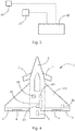
- Fig. 4 shows an example of an aircraft 1, which is equipped with a monitoring system as with reference to FIGS. 1 to 3 has been described, is equipped.
- the aircraft 1 in the form of an aircraft has a fuselage 6 on which wing 2, horizontal tail unit 7 and fin 5 are arranged.
- the horizontal stabilizer 7 is in the example of Fig. 4 arranged in front of the wings 2.
- the horizontal stabilizer 7 can also be arranged behind the wings 2.
- the horizontal stabilizer 7 can have a horizontal stabilizer and a movable elevator. It should be noted that those related to Fig. 4 described principles on all parking spaces (e.g. elevator, rudder, aileron) on an aircraft in particular an aircraft can be used. For the sake of clarity, no rudders are shown on the fin 5 and the horizontal stabilizer 7, but they can of course be present.
- a rudder 3 with a flap 4 is arranged on each of the wings 2.
- An actuator 20 is arranged in the aircraft and via a kinematic arrangement (in Fig. 4 not shown for the sake of clarity) is connected to a rudder 3 in order to move the rudder 3 with respect to the wing 2.
- a first sensor 25 is arranged on the actuator 20 in order to detect an active movement of the actuator 20.
- a second sensor 45 is arranged on the wing 2 in such a way that it detects a movement of the rudder 3 with respect to the wing 2.
- the first sensor 25 and the second sensor 45 are connected to the controller 50 and the computing unit 60 as in FIG Fig. 2 and Fig. 3 shown as an example. This makes it possible to monitor a connection and effect between the actuator 20 and the rudder 3 and to detect or determine inconsistencies or deviations between the movement specified by the actuator 20 and the movement actually carried out by the rudder 3.
- a separate actuator is provided for each control surface in an aircraft, which is assigned exclusively to one control surface.
- a separate sensor (the second sensor 45 described above) is also provided for each control surface, which sensor detects the movement of each control surface.
- the movement of the control surface 3 with respect to the wing 2 or the fuselage 6 can be detected.
- the flap 4 the movement of the flap 4 relative to the rudder can be detected.
- the relative movement of a rudder to the associated fin or the trunk and the relative movement of a flap to the associated rudder can be recorded and compared with the expected movement. This makes it possible to play a game in the kinematic arrangement, which connects an actuator to the control surface assigned to this actuator, and to output a corresponding message so that a further check can be initiated as required.
- more than one sensor can be arranged on a control surface.
Landscapes
- Engineering & Computer Science (AREA)
- Aviation & Aerospace Engineering (AREA)
- Automation & Control Theory (AREA)
- Physics & Mathematics (AREA)
- General Physics & Mathematics (AREA)
- Manufacturing & Machinery (AREA)
- Transportation (AREA)
- Mechanical Engineering (AREA)
- Transmission Devices (AREA)
- Mechanical Control Devices (AREA)
Abstract
Description
- Die Beschreibung betrifft ein System zum Überwachen der Güte einer kinematischen Kopplung zwischen einem Stellglied und einem von dem Stellglied gesteuerten Element. Allgemein betrifft die Beschreibung also ein Überwachungssystem für eine kinematische Kopplung. Daneben betrifft die Beschreibung sicherheitsrelevante Systeme mit einem solchen Überwachungssystem, insbesondere ein Luftfahrzeug mit einem Überwachungssystem.
- In einer Vielzahl von technischen Systemen werden kinematische Kopplungen verwendet, um Bewegung von einer Eingangsseite auf eine Ausgangsseite zu übertragen. Auf der Eingangsseite ist typischerweise ein Stellglied oder ein Antrieb angeordnet, wohingegen auf der Ausgangsseite ein gesteuertes oder bewegtes Element angeordnet ist. Das Stellglied erzeugt eine Bewegung und eine kinematische Kopplung überträgt diese Bewegung auf das gesteuerte Element.
- In nahezu sämtlichen Systemen, in denen eine Bewegung stattfindet, zeigt sich über die Nutzungsdauer dieser Systeme ein mehr oder weniger ausgeprägter Verschleiß. Typischerweise findet ein solcher Verschleiß in der kinematischen Kopplung statt. Der Verschleiß kann aber auch auf das Stellglied oder auf das gesteuerte Element wirken.
- Jedenfalls kann Verschleiß an jeder der genannten Stellen dazu führen, dass eine Bewegung des Stellgliedes auf der Eingangsseite nicht mehr direkt mit einer Bewegung des gesteuerten Elements auf der Ausgangsseite korreliert oder dass sich das gesteuerte Element beim Einwirken von äußeren Kräften auf das gesteuerte Element bewegt, ohne dass sich das Stellglied auf der Eingangsseite bewegt. In diesem Zustand des Systems, welches aus Stellglied, kinematischer Kopplung und gesteuertem Element besteht, kann man sagen, dass das System Spiel aufweist.
- Um Spiel in einem System zu identifizieren, werden komplexe oder sicherheitsrelevante Systeme in regelmäßigen zeitlichen Abständen einer Überprüfung und Wartung unterzogen. Dabei werden die für Spiel anfälligen Systeme oder Subsysteme untersucht und bei Bedarf neu eingestellt, um das Spiel aus dem System zu entfernen.
- Es kann als Aufgabe der Erfindung betrachtet werden, die Überwachung von sicherheitsrelevanten Systemen, die eine kinematische Kopplung enthalten, zu verbessern.
- Diese Aufgabe wird gelöst durch den Gegenstand des unabhängigen Anspruchs. Weitere Ausführungsformen ergeben sich aus den abhängigen Ansprüchen sowie aus der folgenden Beschreibung.
- Gemäß einem Aspekt ist ein Überwachungssystem zum Überwachen einer kinematischen Kopplung zwischen einem Stellglied und einem gesteuerten Element angeben. Das Überwachungssystem weist einen ersten Sensor, einen zweiten Sensor, und eine Recheneinheit auf. Der erste Sensor ist so angeordnet, dass er eine Wirkbewegung des Stellgliedes erfasst und basierend auf der erfassten Wirkbewegung des Stellgliedes ein erstes Signal bereitstellt. Der zweite Sensor ist so angeordnet, dass er eine Bewegung des gesteuerten Elements erfasst und basierend auf der erfassten Bewegung des gesteuerten Elements ein zweites Signal bereitstellt. Die Recheneinheit ist mit dem ersten Sensor und dem zweiten Sensor verbunden und ist ausgestaltet, das erste Signal und das zweite Signal zu empfangen. Die Recheneinheit ist ferner ausgestaltet, basierend auf dem ersten Signal eine erwartete Bewegung des gesteuerten Elements zu ermitteln und die erwartete Bewegung mit der dem zweiten Signal entsprechenden erfassten Bewegung zu vergleichen und eine Abweichung zwischen der erwarteten Bewegung und der erfassten Bewegung bereitzustellen.
- Das hierin beschriebene Überwachungssystem dient dazu, ein kinematisches System und die Bewegung der Bestandteile dieses kinematischen Systems zu überwachen. Typischerweise besteht ein kinematisches System aus einem Antrieb (Stellglied), einer kinematischen Kopplung, und einem gesteuerten Element. Die kinematische Kopplung ist mit dem Stellglied und dem gesteuerten Element so verbunden, dass eine Bewegung des Stellgliedes auf das gesteuerte Element übertragen wird. Die Bewegung des Stellgliedes kann über die kinematische Kopplung mit oder ohne Übersetzung auf das gesteuerte Element übertragen werden. Eingangsseitig kann das Stellglied beispielsweise mittels Stangen, Hebeln und Gelenken oder Scharnieren mit der kinematischen Kopplung verbunden sein, um Kräfte, z.B. Zug- und/oder Druckkräfte, auf die kinematische Kopplung zu übertragen. Ausgangsseitig ist die kinematische Kopplung beispielsweise ebenfalls mittels Stangen, Hebeln und Gelenken oder Scharnieren mit dem gesteuerten Element verbunden, um Kräfte, z.B. Zug- und/oder Druckkräfte, auf das gesteuerte Element zu übertragen.
- Die kinematische Kopplung kann eine translatorische oder rotatorische Bewegung von dem Stellglied auf das gesteuerte Element übertragen. Hierfür kann die kinematische Kopplung verschiedene Elemente aufweisen, um die Übertragung der Bewegung zu bewerkstelligen, nämlich: Stangen, Hebel, Gelenke, Seile, Rollen, Zahnräder oder dergleichen.
- Das hierin beschriebene Überwachungssystem kann vorteilhafterweise dort eingesetzt werden, wo eine Bewegung des Stellgliedes in sehr hohem Maße und mit einer hohen Genauigkeit mit einer Bewegung des gesteuerten Elements korrelieren muss und ein Spiel, welches aus einem der Bestandteile des kinematischen Systems resultiert, höchst unerwünscht ist. Je nach Ausgestaltung des Stellgliedes kann bei dem Stellglied als solches ein Spiel sehr stark reduziert oder sogar ausgeschlossen werden. So zeichnen sich beispielsweise hydraulische Stellglieder als wenig oder gar nicht anfällig für Spiel aus. Ebenso kann das gesteuerte Element so ausgestaltet sein, dass ein Spiel reduziert oder nahezu ausgeschlossen ist. Somit verbleibt als Hauptquelle für Spiel in einem kinematischen System im Wesentlichen die kinematische Kopplung. Das hierin beschriebene Überwachungssystem eignet sich, Spiel in einem kinematischen System zu identifizieren, unabhängig davon, wo dieses Spiel in das System eingebracht wird.
- Das Überwachungssystem setzt darauf, dass die Bewegung des gesteuerten Elements zusätzlich und gesondert durch den zweiten Sensor erfasst wird. Diese tatsächliche Bewegung oder erfasste Bewegung des gesteuerten Elements wird mit einer erwarteten Bewegung des gesteuerten Elements verglichen, wobei die erwartete Bewegung des gesteuerten Elements basierend auf der Bewegung des Stellgliedes bestimmt wird. In anderen Worten wird also die Bewegung des gesteuerten Elements auf zwei Arten bestimmt: einmal als erwartete Bewegung basierend auf der Bewegung des Stellgliedes und zusätzlich als direkte Erfassung seiner tatsächlichen Bewegung mittels des zweiten Sensors.
- Um die erwartete Bewegung des gesteuerten Elements zu ermitteln, nutzt die Recheneinheit eine Ausgangsposition und/oder eine Positionsänderung eines Stellelements des Stellgliedes. Das Stellelement des Stellgliedes stellt die Schnittstelle des Stellgliedes zu der kinematischen Kopplung dar und kann beispielsweise als Stange zum Übertragen von Zug- und Druckkräften oder als Seil zum Übertragen von Zugkräften ausgestaltet sein.
- Der erste Sensor ist an dem Stellglied oder an dem Stellelement des Stellgliedes oder an der Umgebung des Stellgliedes angeordnet, um eine auf die kinematische Kopplung übertragene Bewegung zu ermitteln und in ein Messsignal, das heißt das erste Signal, umzuwandeln. Das erste Signal gibt demnach eine Position oder eine Änderung der Position des Stellelements des Stellgliedes an.
- Der zweite Sensor ist mit dem gesteuerten Element oder mit einer Umgebung des gesteuerten Elements gekoppelt, so dass die Bewegung des gesteuerten Elements erfasst werden kann. Auch für den zweiten Sensor gilt, dass die erfasste Bewegung in ein Messsignal umgewandelt wird, wobei dieses Messsignal als zweites Signal bezeichnet wird. Der zweite Sensor kann beispielsweise an dem gesteuerten Element angeordnet sein. Wenn sich das gesteuerte Element bewegt, kann der zweite Sensor diese Bewegung aufgrund seiner geänderten Position oder Orientierung mit Bezug zu der Umgebung erfassen. Der zweite Sensor kann ebenso an einem Punkt der Umgebung des gesteuerten Elements angeordnet sein, so dass sich das gesteuerte Element mit Bezug zu dem zweiten Sensor bewegt. Jedenfalls dient das zweite Signal dazu, die tatsächliche Bewegung des gesteuerten Elements anzuzeigen.
- Abweichungen zwischen erwarteter und erfasster Bewegung kommen insbesondere dann vor, wenn eine Systemkomponente wie beispielsweise die kinematische Kopplung mechanisches Spiel hat. Ebenso ist es möglich, wenn die kinematische Kopplung Spiel hat, dass sich das gesteuerte Element unter dem Einfluss von äußeren Kräften bewegt ohne dass diese Bewegung von dem Stellglied vorgegeben oder veranlasst wird. Auch dieser Fall stellt eine Abweichung zwischen erwarteter und erfasster Bewegung dar. Die Abweichung kann als Differenz zwischen den zwei Signalen ermittelt werden. Die erwartete Bewegung ist null, weil das Stellglied keine Bewegung vorgegeben hat, wohingegen die erfasste Bewegung eine tatsächliche Bewegung des gesteuerten Elements darstellt.
- Das Stellglied kann ein hydraulisches Element, ein mechanischer Antrieb oder ein elektro-mechanischer Antrieb sein. Das Stellglied ist beispielsweise ausgestaltet, ein Kommandosignal zu empfangen und eine dem Kommandosignal entsprechende Wirkbewegung zu erzeugen. Unter der Maßgabe, dass zwischen dem Kommandosignal und der Wirkbewegung ein direkter Zusammenhang besteht, ist es auch denkbar, dass das Kommandosignal für den Vergleich mit der erfassten Bewegung des gesteuerten Elements verwendet wird.
- Ein Gedanke des hierin beschriebenen Überwachungssystems ist, dass das überwachte System während seiner Betriebszeit einer dauerhaften Überwachung unterzogen wird. Dauerhafte Überwachung bedeutet dabei, dass die ausgehend von der Wirkbewegung des Stellgliedes erwartete Bewegung des gesteuerten Elements wiederkehrend in regelmäßigen oder unregelmäßigen Zeitabständen mit der tatsächlichen Bewegung des gesteuerten Elements verglichen wird und im Falle von Abweichungen (Differenz zwischen erwarteter und tatsächlicher Bewegung bzw. zwischen den entsprechenden Signalen) eine entsprechende Meldung bereitgestellt wird. Gerade bei sicherheitskritischen Anwendungen ist dies hilfreich, weil das Spiel in einem kinematischen System nicht nur in den vorgesehenen Wartungsintervallen, sondern dauerhaft überwacht wird. Dies kann insbesondere dort hilfreich sein, wo ein Spiel aufgrund hoher Kräfte von außen zu einem raschen und starken Verschleiß des Systems bis hin zu seiner Zerstörung führen kann.
- In einer Ausführungsform ist die Recheneinheit ausgestaltet, die Abweichung zwischen der erwarteten Bewegung und der erfassten Bewegung mit einem Schwellwert zu vergleichen und eine Fehlermeldung auszugeben, wenn die Abweichung den Schwellwert erreicht oder überschreitet.
- Insbesondere wird der Betrag der Abweichung zwischen der erwarteten Bewegung und der erfassten Bewegung mit dem Schwellwert verglichen. In der Regel ist allein die Information ausreichend, dass es eine Abweichung gibt, wohingegen die Richtung der Abweichung (positiv oder negativ) zunächst irrelevant ist. In nachfolgenden Mess- und Überprüfungsschritten kann dann die Abweichung genauer untersucht werden.
- Bei einer Schwenkbewegung des gesteuerten Elements kann der Schwellwert für die Abweichung als Winkel angegeben werden. In sicherheitskritischen Umgebungen kann dieser Schwellwert sehr niedrig sein, beispielsweise wenige Millirad (mrad). Es ist aber genauso denkbar, dass der Schwellwert als absolute Auslenkung (Millimeter oder Zentimeter), um die die tatsächliche Bewegung von der erwarteten Bewegung an einem Punkt des gesteuerten Elements abweicht, definiert ist.
- In einer weiteren Ausführungsform ist die Recheneinheit ausgestaltet, die erwartete Bewegung des gesteuerten Elements basierend auf einem Modell der kinematischen Kopplung zu bestimmen.
- Beispielsweise kann das Überwachungssystem in einem Flugzeug verwendet werden, um die Bewegung von Steuerflächen basierend auf Bewegungen von Stellgliedern zu überprüfen bzw. zu überwachen. Von dem Flugzeug liegt ein Modell vor, welches von einer Steuerung oder der Recheneinheit genutzt wird, um die Reaktion von gesteuerten Elementen auf eine Eingabe (d.h. das an das Stellglied übertragene Kommandosignal) zu berechnen. Wird beispielsweise ein Aktuator, der als Stellglied einer Steuerfläche fungiert, betätigt, so kann mit dem Modell des Flugzeugs berechnet werden, wie die Steuerfläche auf eine Eingabe an das Stellglied reagiert. Diese Berechnung entspricht der erwarteten Bewegung des gesteuerten Elements, d.h. der Steuerfläche. Das Modell kann sich dabei auf die kinematische Kopplung zwischen Stellglied und gesteuertem Element beziehen, kann aber auch ein Modell einer übergeordneten Anordnung sein, welche das Stellglied, das gesteuerte Element, und die kinematische Kopplung zwischen Stellglied und gesteuertem Element enthält.
- In einer weiteren Ausführungsform ist sowohl der erste Sensor als auch der zweite Sensor ein Sensor, der ausgewählt ist aus der Gruppe umfassend: einen Bewegungssensor, einen Drehratensensor, einen Rotationspositionssensor, einen Winkelsensor, einen linearen variablen Differenzialtransformator, einen optischen Sensor, einen mechanischen Sensor mit beweglichen Teilen, einen magnetischen Sensor, einen Hall-Effekt-Sensor.
- Insgesamt kann jeder Sensor verwendet werden, welcher geeignet und ausgestaltet ist, eine translatorische oder rotatorische Bewegung des Stellelements des Stellgliedes und/oder des gesteuerten Elements zu erfassen und ein der erfassten Bewegung entsprechendes Signal zu erzeugen und bereitzustellen.
- In einer weiteren Ausführungsform ist der zweite Sensor ausgestaltet, die Bewegung des gesteuerten Elements mit einer Abtastrate von mehr als 1 kHz zu erfassen.
- Das Überwachungssystem ist in dieser Ausführungsform also dafür ausgelegt, rasche und hochfrequente Bewegungen und/oder Schwingungen des gesteuerten Elements zu erfassen, wie sie beispielsweise vorkommen, wenn eine Steuerfläche bei einem Flugzeug unter dem Einfluss der auf sie wirkenden Luftströmung schwingt oder vibriert, wenn die Kinematik, die die Steuerfläche bewegt oder in einer Position hält, Spiel hat. Sowohl der zweite Sensor als auch die Recheneinheit müssen dafür ausgelegt sein, die Abtastrate von mehreren kHz (1 kHz bis hin zu mehreren 10 kHz) zu leisten und die dadurch anfallenden Daten verarbeiten zu können.
- In einer weiteren Ausführungsform ist die Recheneinheit ausgestaltet, das zweite Signal einem Filter zuzuführen und das gefilterte Signal für den Vergleich mit dem ersten Signal zu verwenden.
- Somit können aus dem zweiten Signal Last- und Bewegungsspitzen herausgefiltert werden, welche ggf. aus einer zeitlich stark begrenzten hohen äußeren Kraft resultieren, aber nicht einem Spiel in der Kinematik zuzuordnen sind. Bei sehr hohen äußeren Kräften kann es zu einer Bewegung des gesteuerten Elements kommen einfach aufgrund von elastischer Verformung, auch ohne dass sich das Stellglied bewegt.
- Als Filter kann beispielsweise ein Tiefpassfilter, ein Kalmanfilter, ein Wienerfilter oder ein Korrelationsalgorithmus verwendet werden. Bevorzugt ist ein solches Filter als digitaler Filteralgorithmus ausgestaltet und kann in der Recheneinheit als gesondertes Filtermodul implementiert sein.
- Gemäß einem weiteren Aspekt ist ein Luftfahrzeug angegeben, welches ein Überwachungssystem gemäß einer oder mehrerer hierin beschriebener Ausführungsformen des Überwachungssystems aufweist.
- Das Überwachungssystem kann insbesondere in sicherheitsrelevanten Umgebungen zum Einsatz kommen. Hierbei kann es sich um Luftfahrzeuge handeln. Aber auch andere Anwendungsbereiche mit hohen Sicherheitsanforderungen und damit einhergehenden Anforderungen an die Genauigkeit und das Funktionieren einer kinematischen Kopplung zwischen einem Stellglied und einem davon gesteuerten Element sind möglich.
- Beispielsweise kann das Überwachungssystem in industriellen Anlagen oder Wasserfahrzeugen verwendet werden. In industriellen Anlagen kann das Überwachungssystem beispielsweise in Verbindung mit Schleusen oder Ventilen verwendet werden, deren erwartete Öffnung mit der tatsächlichen Öffnung verglichen wird. Im Kontext von Wasserfahrzeugen kann das
Überwachungssystem ähnlich verwendet werden wie bei Luftfahrzeugen, nämlich dazu, um bewegliche Elemente, die der Wasserströmung (oder der Luftströmung) ausgesetzt sind und von einem Stellglied bewegt werden können, zu überwachen. - Bei dem Luftfahrzeug kann es sich um Flugzeuge, Hubschrauber, oder Drohnen handeln. Insbesondere kann das Überwachungssystem verwendet werden, um eine erwartete Bewegung eines der Luftströmung ausgesetzten Elements mit einer tatsächlichen Bewegung dieses Elements zu vergleichen.
- In einer Ausführungsform des Luftfahrzeugs ist das gesteuerte Element eine Steuerfläche des Luftfahrzeugs und das Stellglied ist ein mit der Steuerfläche über eine kinematische Kopplung verbundener Aktuator.
- Bei dem Aktuator kann es sich um ein hydraulisches, mechanisches oder elektromechanisches Element handeln, welches in der Lage ist, eine Bewegung auszuführen, damit diese Bewegung über die Kinematik auf die Steuerfläche übertragen werden kann und eine Bewegung der Steuerfläche verursacht.
- Bei der Steuerfläche kann es sich beispielsweise um ein Ruder oder eine Klappe eines Flugzeugs handeln, z.B. ein Höhenruder, Querruder, Seitenruder, Canard, eine Trimmklappe, die einem dieser Ruder zugeordnet ist, oder auch um eine Landeklappe. Allgemein kann das Überwachungssystem verwendet werden, um jegliche beweglichen Elemente in einem Luftfahrzeug (und/oder anderen sicherheitsrelevanten Systemen) zu überwachen und deren tatsächliche Bewegung mit der angeforderten Bewegung (d.h. der Soll-Bewegung, die unter gewöhnlichen Bedingungen der Bewegung des Aktuators entspricht) zu vergleichen und im Falle einer Abweichung eine Meldung auszugeben.
- In einer weiteren Ausführungsform des Luftfahrzeugs ist der zweite Sensor angeordnet, um eine Relativbewegung zwischen der Steuerfläche und einem Rumpf oder einer anderen mit dem Rumpf verbundenen Komponente des Luftfahrzeugs zu erfassen.
- Wenn die Steuerfläche ein Ruder ist, wird insbesondere die Relativbewegung zwischen Ruder und Flügel (Querruder oder Landeklappe relativ Flügel, Höhenruder relativ zu Höhenflosse, Seitenruder relativ zu Seitenflosse) erfasst. Wenn es sich bei der Steuerfläche um eine an einem Ruder angebrachte Trimmklappe handelt, kann insbesondere die Relativbewegung zwischen Trimmklappe und zugehörigem Ruder erfasst werden.
- In dieser Ausführungsform ist der zweite Sensor insbesondere ausgestaltet, um eine Schwenkbewegung der Steuerfläche zu erfassen. Der zweite Sensor ist beispielsweise als Winkelsensor, der eine Schwenkbewegung um ein Gelenk der Steuerfläche erfasst, oder als Auslenksensor, der eine absolute Auslenkung der Steuerfläche erfasst, ausgestaltet. Der zweite Sensor ist so angebracht, dass er eine Bewegung der Steuerfläche relativ zu ihrer Umgebung (Rumpf, Flosse, Flügel) oder in einem Gelenk, mit dem die Steuerfläche an ihrer Umgebung angebracht ist, erfassen kann.
- In einer weiteren Ausführungsform des Luftfahrzeugs implementiert die Recheneinheit Funktionen der Flugsteuerung für das Luftfahrzeug.
- Die Recheneinheit kann in einem Beispiel ein Computer sein, welcher Funktionen der Steuerung des Luftfahrzeugs ausführt. Dieser Computer kann seinerseits die Funktionalität der hierin beschriebenen Recheneinheit ausführen. Daneben kann der Computer noch andere Funktionen der Luftfahrzeugsteuerung übernehmen. Alternativ ist es auch möglich, die Funktionen des Recheneinheit von den übrigen Funktionen der Luftfahrzeugsteuerung physikalisch zu trennen, d.h. auf zwei voneinander getrennten Computern auszuführen. Diese Alternative hat den Vorteil, dass das Überwachungssystem in ein bestehendes Luftfahrzeug nachgerüstet werden kann, ohne dass in die bestehenden Systeme eingegriffen werden muss. Lediglich das existierende Steuersignal an den Aktuator bzw. der Messwert des dem Aktuator zugeordneten Sensors muss abgegriffen werden.
- In anderen Worten wird durch das hierin beschriebene Überwachungssystem eine Aufgabe, welche üblicherweise in vorgegebenen Wartungsintervallen am Boden durch ein gesondertes Testgerät ausgeführt wird, teilweise in ein Luftfahrzeug verlagert und in dem Luftfahrzeug während des Betriebs, d.h. in der Luft, ausgeführt. Das Überwachungssystem vergleicht laufend die erwartete Bewegung einer Steuerfläche mit der tatsächlichen Bewegung dieser Steuerfläche und ist in der Lage, bei einer Abweichung, die einen Schwellwert übersteigt, einen Hinweis auf diese Abweichung auszugeben. Sodann kann das Luftfahrzeug einer detaillierten Überprüfung zugeführt werden.
- Nachfolgend wird anhand der beigefügten Zeichnungen näher auf Ausführungsbeispiele der Erfindung eingegangen. Die Darstellungen sind schematisch und nicht maßstabsgetreu. Gleiche Bezugszeichen beziehen sich auf gleiche oder ähnliche Elemente. Es zeigen:
- Fig. 1
- eine schematische Darstellung eines kinematischen Systems mit einem ersten Sensor und einem zweiten Sensor.
- Fig. 2
- eine schematische Darstellung einer Steuerung und eines davon gesteuerten Stellgliedes mit einem ersten Sensor.
- Fig. 3
- eine schematische Darstellung einer Recheneinheit, welche mit einem ersten Sensor und einem zweiten Sensor verbunden ist.
- Fig. 4
- eine schematische Darstellung eines Luftfahrzeugs mit einem Überwachungssystem für die Bewegung einer Steuerfläche.
- Detaillierte Beschreibung von Ausführungsbeispielen
-
Fig. 1 zeigt ein Überwachungssystem 10 für ein kinematisches System. Das kinematische System besteht aus einem Stellglied 20, einer kinematischen Kopplung 30 und einem gesteuerten Element 40. Das Stellglied 20 ist mit einem Stellelement 22 über ein Gelenk 23 mit der kinematischen Kopplung 30 verbunden. Somit können Wirkbewegungen des Stellgliedes 20 über das Stellelement 22 auf die kinematische Kopplung 30 übertragen werden. Das Stellglied 20 und seine Verbindung zu der kinematischen Kopplung 30 stellt die Eingangsseite des kinematischen Systems dar. - Die kinematische Kopplung 30 kann aus einer Vielzahl von miteinander gekoppelten beweglichen mechanischen Elementen bestehen, beispielsweise Hebel, Gelenke, Stangen, Seile, Rollen, Zahnrädern und dergleichen. In
Fig. 1 jedenfalls ist die kinematische Kopplung 30 vereinfacht dargestellt mit einem Hebel, welcher an einem Gelenk bzw. Drehpunkt 33 befestigt und um diesen Drehpunkt 33 drehbar gelagert ist. - In dem in
Fig. 1 gezeigten Beispiel ist die kinematische Kopplung 30 unmittelbar mit dem gesteuerten Element 40 verbunden. Eine Bewegung, welche über die kinematische Kopplung 30 übertragen wird, wirkt sich somit auf das gesteuerte Element 40 aus. Das gesteuerte Element 40 und seine Verbindung mit der kinematischen Kopplung 30 stellt die Ausgangsseite des kinematischen Systems dar. - In dem in
Fig. 1 gezeigten Beispiel kann das Stellglied 20 über das Stellelement 22 eine translatorische Bewegung (inFig. 1 nach links oder nach rechts) auf die kinematische Kopplung geben. Der Hebel der kinematischen Kopplung schwenkt um den Drehpunkt 33. Diese Schwenkbewegung wird ihrerseits auf das gesteuerte Element 40 gegeben und kann das gesteuerte Element 40 translatorisch oder rotatorisch bewegen, beispielsweise indem eine Drehbewegung um den Drehpunkt 42 verursacht wird. - Kinematische Systeme können in hochsensiblen bzw. hochpräzisen Systemen, beispielsweise Luftfahrzeugen, verwendet werden. Wie weiter oben beschrieben, stellt die Ansteuerung von Steuerflächen eines Luftfahrzeugs ein kinematisches System dar.
- Die Eingangsseite des kinematischen Systems ist mit der Ausgangsseite des kinematischen Systems wirkverbunden. Das bedeutet, dass eine auf der Eingangsseite eingespeiste Wirkung sich auf der Ausgangsseite bemerkbar macht. Zwischen der auf der Eingangsseite eingespeisten Wirkung (Bewegung) und der auf der Ausgangsseite erfolgten Wirkung (Bewegung) herrscht ein strenger Zusammenhang: (1) eine auf der Eingangsseite eingespeiste Wirkung führt zu einer vorhersagbaren Wirkung auf der Ausgangsseite und (2) ohne eine auf der Ausgangsseite eingespeiste Wirkung gibt es auf der Ausgangsseite ebenfalls keine Wirkung, d.h. die Ausgangsseite hält eine vorliegende Position. Spiel in dem kinematischen System führt dazu, dass dieser Zusammenhang so nicht mehr gegeben ist. Im Falle von Spiel ist nicht mehr vorhersagbar, wie die Wirkung auf der Ausgangsseite bei einer bestimmten auf der Eingangsseite eingespeisten Wirkung ausfällt und es kann dazu kommen, dass sich das gesteuerte Element bewegt, selbst wenn das Stellglied auf der Eingangsseite keine Bewegung ausführt.
- Um das Spiel in einem solchen unerwünschten Zustand zu erkennen, ist vorgesehen, dass ein erster Sensor 25 an oder in der Nähe des Stellgliedes 20 angeordnet ist, um eine Wirkbewegung des Stellglied 20 auf der Eingangsseite zu erfassen, und ein zweiter Sensor 45 an oder in der Nähe des gesteuerten Elements 40 angeordnet ist, um eine tatsächliche Bewegung des gesteuerten Elements 40 zu erfassen.
- Es ist denkbar, dass stellvertretend für das Signal des ersten Sensors 25 für die Wirkbewegung des Stellgliedes 20 ein Kommandosignal, welches an das Stellglied 20 übergeben wird, verwendet wird. Es kann jedoch vorteilhaft sein, wenn die Wirkbewegung des Stellgliedes 20 unmittelbar von dem ersten Sensor 25 erfasst wird. Das Überwachungssystem wie hierin beschrieben ist zunächst darauf ausgelegt, eine Korrelation bzw. Proportionalität der Bewegungen zwischen Eingangsseite und Ausgangsseite des Systems zu überwachen, wobei sich dies auf die tatsächlichen Bewegungen bezieht und nicht unbedingt auf die auf der Eingangsseite über die Kommandosignale angewiesene Bewegung.
- Die von dem ersten Sensor 25 und dem zweiten Sensor 45 ausgegebenen Signale werden herangezogen, um die erwartete Bewegung des gesteuerten Elements basierend auf dem Signal des ersten Sensors 25 und die tatsächliche Bewegung basierend auf dem Signal des zweiten Sensors 45 zu ermitteln und miteinander zu vergleichen. Diese Funktion wird von einer Recheneinheit 60 (siehe
Fig. 3 ) ausgeführt. -
Fig. 2 zeigt beispielhaft, wie auf der Eingangsseite des kinematischen Systems das Stellglied 20 von einer Steuerung 50 gesteuert und überwacht wird. In einem Luftfahrzeug kann die Steuerung 50 auch als Flugsteuerrechner bezeichnet werden. Die Steuerung 50 gibt ein Kommandosignal an das Stellglied 20 und der erste Sensor 25 misst eine erfolgte Wirkbewegung des Stellgliedes 20. Diese von dem ersten Sensor 25 gemessene Wirkbewegung des Stellgliedes 20 wird von dem ersten Sensor in ein erstes Signal umgewandelt und an die Steuerung 50 übermittelt. Die Steuerung 50 nutzt dann das erste Signal, um einen Zustand des kinematischen Systems (beispielsweise einer Steuerfläche des Luftfahrzeugs) basierend auf einem Modell zu ermitteln. Dieser Zustand wird von der Steuerung 50 als Grundlage für das Steuern des Luftfahrzeugs ermittelt. - In Ergänzung zu dem in
Fig. 1 gezeigten kinematischen System zeigtFig. 3 auszugsweise eine Verbindung der beiden Sensoren 25, 45 mit der Recheneinheit 60. Die Recheneinheit 60 erhält zusätzlich zu der Steuerung 50 ausFig. 2 die Signale von dem ersten Sensor 25 und dem zweiten Sensor 45. Die Recheneinheit ermittelt basierend auf dem ersten Signal des ersten Sensors 25 eine erwartete Wirkbewegung auf der Ausgangsseite und vergleicht diese erwartete Wirkbewegung auf der Ausgangsseite mit der von dem zweiten Sensor 45 über ein zweites Signal kommunizierten, tatsächlichen Wirkbewegung auf der Ausgangsseite. - Die Recheneinheit 60 kann die erwartete Wirkbewegung auf der Ausgangsseite unabhängig von der Steuerung 50 ermitteln. Es ist allerdings ebenso denkbar, dass die Recheneinheit 60 mit der Steuerung 50 kommunikativ verbunden ist, und die erwartete Wirkbewegung auf der Ausgangsseite von der Steuerung 50 erhält, weil die Steuerung 50 die erwartete Wirkbewegung auf der Ausgangsseite sowieso für die Zwecke der Flugsteuerung ermittelt.
- Stellt die Recheneinheit 60 fest, dass es zwischen der erwarteten Wirkbewegung und der tatsächlichen Wirkbewegung eine Abweichung gibt, welche einen Schwellwert übersteigt, wird eine Meldung ausgegeben, welche auf diese Inkonsistenz bzw. auf dieses Spiel in dem kinematischen System hinweist.
-
Fig. 4 zeigt beispielhaft ein Luftfahrzeug 1, welches mit einem Überwachungssystem wie mit Bezug zuFig. 1 bis Fig. 3 beschrieben wurde, ausgestattet ist. - Das Luftfahrzeug 1 in Form eines Flugzeugs weist einen Rumpf 6 auf, an welchem Flügel 2, Höhenleitwerk 7 und Seitenflosse 5 angeordnet sind. Das Höhenleitwerk 7 ist in dem Beispiel der
Fig. 4 vor den Flügeln 2 angeordnet. Natürlich kann das Höhenleitwerk 7 auch hinter den Flügeln 2 angeordnet sein. Das Höhenleitwerk 7 kann eine Höhenflosse und ein bewegliches Höhenruder aufweisen. Es sei angemerkt, dass die mit Bezug zuFig. 4 beschriebenen Prinzipien auf sämtliche Stellflächen (z.B. Höhenruder, Seitenruder, Querruder) an einem Luftfahrzeug, insbesondere einem Flugzeug, angewendet werden können. Aus Übersichtlichkeitsgründen sind an der Seitenflosse 5 und dem Höhenleitwerk 7 keine Ruder eingezeichnet, können aber selbstverständlich vorhanden sein. - An den Flügeln 2 ist jeweils ein Ruder 3 mit einer Klappe 4 angeordnet. In dem Flugzeug ist ein Stellglied 20 angeordnet und über eine kinematische Anordnung (in
Fig. 4 der Übersichtlichkeit halber nicht dargestellt) mit einem Ruder 3 verbunden, um das Ruder 3 mit Bezug zu dem Flügel 2 zu bewegen. An dem Stellglied 20 ist ein erster Sensor 25 angeordnet, um eine Wirkbewegung des Stellgliedes 20 zu erfassen. An dem Flügel 2 ist ein zweiter Sensor 45 so angeordnet, dass er eine Bewegung des Ruders 3 mit Bezug zu dem Flügel 2 erfasst. - Der erste Sensor 25 und der zweite Sensor 45 sind mit der Steuerung 50 und der Recheneinheit 60 so verbunden, wie in
Fig. 2 undFig. 3 beispielhaft gezeigt. Somit wird ermöglicht, eine Verbindung und Wirkung zwischen dem Stellglied 20 und dem Ruder 3 zu überwachen und Inkonsistenzen oder Abweichungen zwischen der von dem Stellglied 20 vorgegebenen Bewegung und der von dem Ruder 3 tatsächlich ausgeführten Bewegung zu erfassen bzw. zu ermitteln. - Typischerweise ist für jede Steuerfläche in einem Flugzeug ein eigenes Stellglied vorgesehen, welches ausschließlich einer Steuerfläche zugeordnet ist. Im Zusammenhang mit dem hier beschriebenen Überwachungssystem ist auch für jede Steuerfläche ein eigener Sensor (der oben beschriebene zweite Sensor 45) vorgesehen, welcher die Bewegung jeder Steuerfläche erfasst. Beispielsweise kann die Bewegung der Steuerfläche 3 mit Bezug zu dem Flügel 2 oder dem Rumpf 6 erfasst werden. Betreffend die Klappe 4 kann die Relativbewegung der Klappe 4 zu dem Ruder erfasst werden. Grundsätzlich kann die Relativbewegung eines Ruders zu der zugehörigen Flosse oder dem Rumpf und die Relativbewegung einer Klappe zu dem zugehörigen Ruder erfasst und mit der erwarteten Bewegung verglichen werden. Dies ermöglicht es, ein Spiel in der kinematischen Anordnung, welche ein Stellglied mit der diesem Stellglied zugeordneten Steuerfläche verbindet, zu identifizieren und eine entsprechende Meldung auszugeben, so dass bedarfsorientiert eine weitere Überprüfung eingeleitet werden kann.
- Aus Redundanzgründen können an einer Steuerfläche mehr als ein Sensor angeordnet sein.
- Ergänzend ist darauf hinzuweisen, dass "umfassend" oder "aufweisend" keine anderen Elemente oder Schritte ausschließt und "eine" oder "ein" keine Vielzahl ausschließt. Ferner sei darauf hingewiesen, dass Merkmale oder Schritte, die mit Verweis auf eines der obigen Ausführungsbeispiele beschrieben worden sind, auch in Kombination mit anderen Merkmalen oder Schritten anderer oben beschriebener Ausführungsbeispiele verwendet werden können. Bezugszeichen in den Ansprüchen sind nicht als Einschränkung anzusehen.
-
- 1
- Luftfahrzeug
- 2
- Flügel
- 3
- Ruder
- 4
- Klappe
- 5
- Seitenflosse
- 6
- Rumpf
- 7
- Höhenleitwerk
- 10
- Überwachungssystem
- 20
- Stellglied
- 22
- Stellelement
- 23
- Gelenk
- 25
- erster Sensor
- 30
- Kinematik (Hebel, Gelenke, Gestänge)
- 33
- Gelenk, Drehpunkt
- 40
- gesteuertes Element
- 42
- Drehpunkt
- 45
- zweiter Sensor
- 50
- Steuerung
- 60
- Recheneinheit
Claims (10)
- Überwachungssystem (10) zum Überwachen einer kinematischen Kopplung (30) zwischen einem Stellglied (20) und einem gesteuerten Element (40), wobei das Überwachungssystem aufweist:einen ersten Sensor (25), der so angeordnet ist, dass er eine Wirkbewegung des Stellgliedes (20) erfasst und basierend auf der erfassten Wirkbewegung des Stellgliedes ein erstes Signal bereitstellt;einen zweiten Sensor (45), der so angeordnet ist, dass er eine Bewegung des gesteuerten Elements (40) erfasst und basierend auf der erfassten Bewegung des gesteuerten Elements ein zweites Signal bereitstellt;eine Recheneinheit (60), welche mit dem ersten Sensor (25) und dem zweiten Sensor (45) verbunden ist und ausgestaltet ist, das erste Signal und das zweite Signal zu empfangen;wobei die Recheneinheit (60) ausgestaltet ist, basierend auf dem ersten Signal eine erwartete Bewegung des gesteuerten Elements zu ermitteln und die erwartete Bewegung mit der dem zweiten Signal entsprechenden erfassten Bewegung zu vergleichen und eine Abweichung zwischen der erwarteten Bewegung und der erfassten Bewegung bereitzustellen.
- Überwachungssystem (10) nach Anspruch 1,
wobei die Recheneinheit (60) ausgestaltet ist, die Abweichung zwischen der erwarteten Bewegung und der erfassten Bewegung mit einem Schwellwert zu vergleichen und eine Fehlermeldung auszugeben, wenn die Abweichung den Schwellwert erreicht oder überschreitet. - Überwachungssystem (10) nach Anspruch 1 oder 2,
wobei die Recheneinheit (60) ausgestaltet ist, die erwartete Bewegung des gesteuerten Elements (40) basierend auf einem Modell der kinematischen Kopplung (30) zu bestimmen. - Überwachungssystem (10) nach einem der vorhergehenden Ansprüche,
wobei sowohl der erste Sensor (25) als auch der zweite Sensor (45) ein Sensor ist, der ausgewählt ist aus der Gruppe umfassend: einen Bewegungssensor, einen Drehratensensor, einen Rotationspositionssensor, einen Winkelsensor, einen linearen variablen Differenzialtransformator, einen optischen Sensor, einen mechanischen Sensor mit beweglichen Teilen, einen magnetischen Sensor, einen Hall-Effekt-Sensor. - Überwachungssystem (10) nach einem der vorhergehenden Ansprüche,
wobei der zweite Sensor (45) ausgestaltet ist, die Bewegung des gesteuerten Elements (40) mit einer Abtastrate von mehr als 1 kHz zu erfassen. - Überwachungssystem (10) nach einem der vorhergehenden Ansprüche,
wobei die Recheneinheit (60) ausgestaltet ist, das zweite Signal einem Filter zuzuführen und das gefilterte Signal für den Vergleich mit dem ersten Signal zu verwenden. - Luftfahrzeug (1), aufweisend ein Überwachungssystem (10) nach einem der vorhergehenden Ansprüche.
- Luftfahrzeug (1), nach Anspruch 7,
wobei das gesteuerte Element (40) eine Steuerfläche (3, 4) des Luftfahrzeugs (1) ist;
wobei das Stellglied (20) ein mit der Steuerfläche (3, 4) über eine kinematische Kopplung (30) verbundener Aktuator ist. - Luftfahrzeug (1) nach Anspruch 8,
wobei der zweite Sensor (45) angeordnet ist, um eine Relativbewegung zwischen der Steuerfläche (3, 4) und einem Rumpf (3) oder einer anderen mit dem Rumpf (3) verbundenen Komponente des Luftfahrzeugs (9) zu erfassen. - Luftfahrzeug (1) nach einem der Ansprüche 7 bis 9,
wobei die Recheneinheit (60) Funktionen der Flugsteuerung für das Luftfahrzeug implementiert.
Applications Claiming Priority (1)
| Application Number | Priority Date | Filing Date | Title |
|---|---|---|---|
| DE102019134215.5A DE102019134215A1 (de) | 2019-12-12 | 2019-12-12 | Überwachungssystem für eine Anordnung mit kinematischer Kopplung |
Publications (2)
| Publication Number | Publication Date |
|---|---|
| EP3835200A1 true EP3835200A1 (de) | 2021-06-16 |
| EP3835200B1 EP3835200B1 (de) | 2024-03-20 |
Family
ID=73792957
Family Applications (1)
| Application Number | Title | Priority Date | Filing Date |
|---|---|---|---|
| EP20212918.5A Active EP3835200B1 (de) | 2019-12-12 | 2020-12-09 | Überwachungssystem für eine anordnung mit kinematischer kopplung |
Country Status (3)
| Country | Link |
|---|---|
| US (1) | US11708178B2 (de) |
| EP (1) | EP3835200B1 (de) |
| DE (1) | DE102019134215A1 (de) |
Cited By (1)
| Publication number | Priority date | Publication date | Assignee | Title |
|---|---|---|---|---|
| EP4671122A1 (de) * | 2024-06-28 | 2025-12-31 | Dassault Aviation | Verfahren zur erkennung eines spiels in einer steuerfläche und entsprechendes detektionssystem |
Families Citing this family (1)
| Publication number | Priority date | Publication date | Assignee | Title |
|---|---|---|---|---|
| EP4434877A1 (de) * | 2023-03-22 | 2024-09-25 | Lilium eAircraft GmbH | Elektrisches servosystem für eine flugsteuerfläche, verfahren zur erkennung von sensorfehlern und verfahren zur bestimmung der korrekten funktion eines bewegungsbezogenen flugsteuerflächensensors |
Citations (4)
| Publication number | Priority date | Publication date | Assignee | Title |
|---|---|---|---|---|
| US20130026287A1 (en) * | 2011-07-28 | 2013-01-31 | Airbus Operations (Sas) | Method And Device For Detecting An Uncontrolled Movement Of An Aircraft Control Surface |
| EP3012192A1 (de) * | 2014-10-24 | 2016-04-27 | Airbus Operations GmbH | Verfahren zur Ermittlung eines Zustands einer Komponente in einem Hochauftriebssystem eines Flugzeugs, Hochauftriebssystem eines Flugzeugs und Flugzeug mit solch einem Hochauftriebssystem |
| US20180029690A1 (en) * | 2016-08-01 | 2018-02-01 | Textron Aviation Inc. | Actuator hardover monitor |
| US20190144135A1 (en) * | 2016-04-20 | 2019-05-16 | Safran Electronics & Defense | Method for estimating the play in an electromechanical actuator |
Family Cites Families (2)
| Publication number | Priority date | Publication date | Assignee | Title |
|---|---|---|---|---|
| US8864101B1 (en) * | 2010-09-14 | 2014-10-21 | Lynn A. Buckner | Machine implemented utility valve exercising apparatus |
| EP3403927B1 (de) * | 2017-05-18 | 2019-07-03 | AIRBUS HELICOPTERS DEUTSCHLAND GmbH | Verfahren zur steuerung eines künstlichen kraftgefühls auf einem inzeptor eines fahrzeugsteuerungssystems mit einem automatischen flugkontrollsystem |
-
2019
- 2019-12-12 DE DE102019134215.5A patent/DE102019134215A1/de not_active Ceased
-
2020
- 2020-12-09 EP EP20212918.5A patent/EP3835200B1/de active Active
- 2020-12-11 US US17/119,289 patent/US11708178B2/en active Active
Patent Citations (4)
| Publication number | Priority date | Publication date | Assignee | Title |
|---|---|---|---|---|
| US20130026287A1 (en) * | 2011-07-28 | 2013-01-31 | Airbus Operations (Sas) | Method And Device For Detecting An Uncontrolled Movement Of An Aircraft Control Surface |
| EP3012192A1 (de) * | 2014-10-24 | 2016-04-27 | Airbus Operations GmbH | Verfahren zur Ermittlung eines Zustands einer Komponente in einem Hochauftriebssystem eines Flugzeugs, Hochauftriebssystem eines Flugzeugs und Flugzeug mit solch einem Hochauftriebssystem |
| US20190144135A1 (en) * | 2016-04-20 | 2019-05-16 | Safran Electronics & Defense | Method for estimating the play in an electromechanical actuator |
| US20180029690A1 (en) * | 2016-08-01 | 2018-02-01 | Textron Aviation Inc. | Actuator hardover monitor |
Cited By (2)
| Publication number | Priority date | Publication date | Assignee | Title |
|---|---|---|---|---|
| EP4671122A1 (de) * | 2024-06-28 | 2025-12-31 | Dassault Aviation | Verfahren zur erkennung eines spiels in einer steuerfläche und entsprechendes detektionssystem |
| FR3163920A1 (fr) * | 2024-06-28 | 2026-01-02 | Dassault Aviation | Méthode de détection d'un jeu dans une gouverne et système de détection associé |
Also Published As
| Publication number | Publication date |
|---|---|
| DE102019134215A1 (de) | 2021-06-17 |
| EP3835200B1 (de) | 2024-03-20 |
| US11708178B2 (en) | 2023-07-25 |
| US20210179297A1 (en) | 2021-06-17 |
Similar Documents
| Publication | Publication Date | Title |
|---|---|---|
| EP2240365B1 (de) | System zur betätigung von zumindest einer stellklappe eines flugzeugs sowie ein verfahren zur überprüfung des systems | |
| DE10313728B4 (de) | Klappensystem am Tragflügel eines Starrflügel-Flugzeuges | |
| DE69305112T2 (de) | Primäres mehrachsig redundantes vollelektrisches Flugsteuersystem | |
| EP2328806B1 (de) | Fehlertolerantes stellsystem zur verstellung von klappen eines flugzeugs mit einer verstellkinematik mit feststehender drehachse sowie verfahren zur überwachung eines stellsystems | |
| DE102013013340B4 (de) | Klappensystem für ein Flugzeughochauftriebsystem oder eine Triebwerksaktuation und Verfahren zur Überwachung eines Klappensystems | |
| EP2251258B1 (de) | Flugzeughochauftriebssystem sowie Verfahren zur Ermittlung eines Betriebszustandes eines Flugzeughochauftriebssystems | |
| EP2435308B1 (de) | Flugzeug mit einem hochauftriebssystem | |
| EP3563527B1 (de) | Flugsteuersystem | |
| EP3605256B1 (de) | System und verfahren zum überwachen des zustands eines unbemannten luftfahrzeugs | |
| EP1685026A1 (de) | Verfahren zur lastbegrenzung in antriebssystemen für flugzeughochauftriebssysteme | |
| DE102010044678A1 (de) | Überwachungsvorrichtung für ein Stellsystem eines Flugzeugs, Stellsystem und Verfahren zur Rekonfiguration des Stellsystems | |
| DE102009017653A1 (de) | Hochauftriebssystem eines Flugzeugs, Flugzeugsystem und Propeller-Flugzeug mit einem Hochauftriebssystem | |
| DE102008023628A1 (de) | Stellsystem für eine hydraulisch betätigbare Höhenflosse und Testverfahren zur Überprüfung der Integrität eines Stellsystems | |
| EP2891827B1 (de) | Elektromechanisch betätigte Entkoppelvorrichtung für Aktuatoren | |
| EP3835200B1 (de) | Überwachungssystem für eine anordnung mit kinematischer kopplung | |
| EP2449288B1 (de) | Elektromechanische linearstelleinheit | |
| DE102009038781A1 (de) | Vorrichtung zum vorzeitigen Erfassen des Schließzustandes eines Verschlusselementes für eine Raumöffnung | |
| DE102019114463B4 (de) | Überlast- und Bruch-Überwachungsverfahren und -system für ein Hochauftriebssystem eines Flugzeugs | |
| DE102013206060B4 (de) | System zur Betätigung einer Stellklappe an einem Flügel eines Flugzeugs | |
| DE102023110940A1 (de) | System und Verfahren zur Überwachung und/oder Erkennung eines Betriebszustands einer bewegbaren Komponente eines Luftfahrzeuges | |
| DE102013206059B4 (de) | System und Verfahren zur Betätigung einer Stellklappe an einem Flügel eines Flugzeugs und Verfahren zur Funktionsprüfung | |
| EP3411767A1 (de) | Luftfahrzeug | |
| DE1481509A1 (de) | ?lugzeug Steuerungssystem |
Legal Events
| Date | Code | Title | Description |
|---|---|---|---|
| PUAI | Public reference made under article 153(3) epc to a published international application that has entered the european phase |
Free format text: ORIGINAL CODE: 0009012 |
|
| STAA | Information on the status of an ep patent application or granted ep patent |
Free format text: STATUS: THE APPLICATION HAS BEEN PUBLISHED |
|
| AK | Designated contracting states |
Kind code of ref document: A1 Designated state(s): AL AT BE BG CH CY CZ DE DK EE ES FI FR GB GR HR HU IE IS IT LI LT LU LV MC MK MT NL NO PL PT RO RS SE SI SK SM TR |
|
| STAA | Information on the status of an ep patent application or granted ep patent |
Free format text: STATUS: REQUEST FOR EXAMINATION WAS MADE |
|
| 17P | Request for examination filed |
Effective date: 20211122 |
|
| RBV | Designated contracting states (corrected) |
Designated state(s): AL AT BE BG CH CY CZ DE DK EE ES FI FR GB GR HR HU IE IS IT LI LT LU LV MC MK MT NL NO PL PT RO RS SE SI SK SM TR |
|
| STAA | Information on the status of an ep patent application or granted ep patent |
Free format text: STATUS: EXAMINATION IS IN PROGRESS |
|
| 17Q | First examination report despatched |
Effective date: 20221027 |
|
| GRAP | Despatch of communication of intention to grant a patent |
Free format text: ORIGINAL CODE: EPIDOSNIGR1 |
|
| STAA | Information on the status of an ep patent application or granted ep patent |
Free format text: STATUS: GRANT OF PATENT IS INTENDED |
|
| INTG | Intention to grant announced |
Effective date: 20231109 |
|
| GRAS | Grant fee paid |
Free format text: ORIGINAL CODE: EPIDOSNIGR3 |
|
| GRAA | (expected) grant |
Free format text: ORIGINAL CODE: 0009210 |
|
| STAA | Information on the status of an ep patent application or granted ep patent |
Free format text: STATUS: THE PATENT HAS BEEN GRANTED |
|
| AK | Designated contracting states |
Kind code of ref document: B1 Designated state(s): AL AT BE BG CH CY CZ DE DK EE ES FI FR GB GR HR HU IE IS IT LI LT LU LV MC MK MT NL NO PL PT RO RS SE SI SK SM TR |
|
| REG | Reference to a national code |
Ref country code: GB Ref legal event code: FG4D Free format text: NOT ENGLISH |
|
| REG | Reference to a national code |
Ref country code: CH Ref legal event code: EP |
|
| REG | Reference to a national code |
Ref country code: DE Ref legal event code: R096 Ref document number: 502020007395 Country of ref document: DE |
|
| REG | Reference to a national code |
Ref country code: IE Ref legal event code: FG4D Free format text: LANGUAGE OF EP DOCUMENT: GERMAN |
|
| PG25 | Lapsed in a contracting state [announced via postgrant information from national office to epo] |
Ref country code: LT Free format text: LAPSE BECAUSE OF FAILURE TO SUBMIT A TRANSLATION OF THE DESCRIPTION OR TO PAY THE FEE WITHIN THE PRESCRIBED TIME-LIMIT Effective date: 20240320 |
|
| REG | Reference to a national code |
Ref country code: LT Ref legal event code: MG9D |
|
| PG25 | Lapsed in a contracting state [announced via postgrant information from national office to epo] |
Ref country code: GR Free format text: LAPSE BECAUSE OF FAILURE TO SUBMIT A TRANSLATION OF THE DESCRIPTION OR TO PAY THE FEE WITHIN THE PRESCRIBED TIME-LIMIT Effective date: 20240621 |
|
| PG25 | Lapsed in a contracting state [announced via postgrant information from national office to epo] |
Ref country code: HR Free format text: LAPSE BECAUSE OF FAILURE TO SUBMIT A TRANSLATION OF THE DESCRIPTION OR TO PAY THE FEE WITHIN THE PRESCRIBED TIME-LIMIT Effective date: 20240320 Ref country code: RS Free format text: LAPSE BECAUSE OF FAILURE TO SUBMIT A TRANSLATION OF THE DESCRIPTION OR TO PAY THE FEE WITHIN THE PRESCRIBED TIME-LIMIT Effective date: 20240620 |
|
| REG | Reference to a national code |
Ref country code: NL Ref legal event code: MP Effective date: 20240320 |
|
| PG25 | Lapsed in a contracting state [announced via postgrant information from national office to epo] |
Ref country code: RS Free format text: LAPSE BECAUSE OF FAILURE TO SUBMIT A TRANSLATION OF THE DESCRIPTION OR TO PAY THE FEE WITHIN THE PRESCRIBED TIME-LIMIT Effective date: 20240620 Ref country code: NO Free format text: LAPSE BECAUSE OF FAILURE TO SUBMIT A TRANSLATION OF THE DESCRIPTION OR TO PAY THE FEE WITHIN THE PRESCRIBED TIME-LIMIT Effective date: 20240620 Ref country code: LT Free format text: LAPSE BECAUSE OF FAILURE TO SUBMIT A TRANSLATION OF THE DESCRIPTION OR TO PAY THE FEE WITHIN THE PRESCRIBED TIME-LIMIT Effective date: 20240320 Ref country code: HR Free format text: LAPSE BECAUSE OF FAILURE TO SUBMIT A TRANSLATION OF THE DESCRIPTION OR TO PAY THE FEE WITHIN THE PRESCRIBED TIME-LIMIT Effective date: 20240320 Ref country code: GR Free format text: LAPSE BECAUSE OF FAILURE TO SUBMIT A TRANSLATION OF THE DESCRIPTION OR TO PAY THE FEE WITHIN THE PRESCRIBED TIME-LIMIT Effective date: 20240621 Ref country code: FI Free format text: LAPSE BECAUSE OF FAILURE TO SUBMIT A TRANSLATION OF THE DESCRIPTION OR TO PAY THE FEE WITHIN THE PRESCRIBED TIME-LIMIT Effective date: 20240320 Ref country code: BG Free format text: LAPSE BECAUSE OF FAILURE TO SUBMIT A TRANSLATION OF THE DESCRIPTION OR TO PAY THE FEE WITHIN THE PRESCRIBED TIME-LIMIT Effective date: 20240320 |
|
| PG25 | Lapsed in a contracting state [announced via postgrant information from national office to epo] |
Ref country code: SE Free format text: LAPSE BECAUSE OF FAILURE TO SUBMIT A TRANSLATION OF THE DESCRIPTION OR TO PAY THE FEE WITHIN THE PRESCRIBED TIME-LIMIT Effective date: 20240320 Ref country code: LV Free format text: LAPSE BECAUSE OF FAILURE TO SUBMIT A TRANSLATION OF THE DESCRIPTION OR TO PAY THE FEE WITHIN THE PRESCRIBED TIME-LIMIT Effective date: 20240320 |
|
| PG25 | Lapsed in a contracting state [announced via postgrant information from national office to epo] |
Ref country code: NL Free format text: LAPSE BECAUSE OF FAILURE TO SUBMIT A TRANSLATION OF THE DESCRIPTION OR TO PAY THE FEE WITHIN THE PRESCRIBED TIME-LIMIT Effective date: 20240320 |
|
| PG25 | Lapsed in a contracting state [announced via postgrant information from national office to epo] |
Ref country code: NL Free format text: LAPSE BECAUSE OF FAILURE TO SUBMIT A TRANSLATION OF THE DESCRIPTION OR TO PAY THE FEE WITHIN THE PRESCRIBED TIME-LIMIT Effective date: 20240320 |
|
| PG25 | Lapsed in a contracting state [announced via postgrant information from national office to epo] |
Ref country code: IS Free format text: LAPSE BECAUSE OF FAILURE TO SUBMIT A TRANSLATION OF THE DESCRIPTION OR TO PAY THE FEE WITHIN THE PRESCRIBED TIME-LIMIT Effective date: 20240720 |
|
| PG25 | Lapsed in a contracting state [announced via postgrant information from national office to epo] |
Ref country code: SM Free format text: LAPSE BECAUSE OF FAILURE TO SUBMIT A TRANSLATION OF THE DESCRIPTION OR TO PAY THE FEE WITHIN THE PRESCRIBED TIME-LIMIT Effective date: 20240320 Ref country code: PT Free format text: LAPSE BECAUSE OF FAILURE TO SUBMIT A TRANSLATION OF THE DESCRIPTION OR TO PAY THE FEE WITHIN THE PRESCRIBED TIME-LIMIT Effective date: 20240722 |
|
| PG25 | Lapsed in a contracting state [announced via postgrant information from national office to epo] |
Ref country code: ES Free format text: LAPSE BECAUSE OF FAILURE TO SUBMIT A TRANSLATION OF THE DESCRIPTION OR TO PAY THE FEE WITHIN THE PRESCRIBED TIME-LIMIT Effective date: 20240320 |
|
| PG25 | Lapsed in a contracting state [announced via postgrant information from national office to epo] |
Ref country code: CZ Free format text: LAPSE BECAUSE OF FAILURE TO SUBMIT A TRANSLATION OF THE DESCRIPTION OR TO PAY THE FEE WITHIN THE PRESCRIBED TIME-LIMIT Effective date: 20240320 Ref country code: EE Free format text: LAPSE BECAUSE OF FAILURE TO SUBMIT A TRANSLATION OF THE DESCRIPTION OR TO PAY THE FEE WITHIN THE PRESCRIBED TIME-LIMIT Effective date: 20240320 |
|
| PG25 | Lapsed in a contracting state [announced via postgrant information from national office to epo] |
Ref country code: PL Free format text: LAPSE BECAUSE OF FAILURE TO SUBMIT A TRANSLATION OF THE DESCRIPTION OR TO PAY THE FEE WITHIN THE PRESCRIBED TIME-LIMIT Effective date: 20240320 |
|
| PG25 | Lapsed in a contracting state [announced via postgrant information from national office to epo] |
Ref country code: SK Free format text: LAPSE BECAUSE OF FAILURE TO SUBMIT A TRANSLATION OF THE DESCRIPTION OR TO PAY THE FEE WITHIN THE PRESCRIBED TIME-LIMIT Effective date: 20240320 |
|
| PG25 | Lapsed in a contracting state [announced via postgrant information from national office to epo] |
Ref country code: SM Free format text: LAPSE BECAUSE OF FAILURE TO SUBMIT A TRANSLATION OF THE DESCRIPTION OR TO PAY THE FEE WITHIN THE PRESCRIBED TIME-LIMIT Effective date: 20240320 Ref country code: SK Free format text: LAPSE BECAUSE OF FAILURE TO SUBMIT A TRANSLATION OF THE DESCRIPTION OR TO PAY THE FEE WITHIN THE PRESCRIBED TIME-LIMIT Effective date: 20240320 Ref country code: RO Free format text: LAPSE BECAUSE OF FAILURE TO SUBMIT A TRANSLATION OF THE DESCRIPTION OR TO PAY THE FEE WITHIN THE PRESCRIBED TIME-LIMIT Effective date: 20240320 Ref country code: PT Free format text: LAPSE BECAUSE OF FAILURE TO SUBMIT A TRANSLATION OF THE DESCRIPTION OR TO PAY THE FEE WITHIN THE PRESCRIBED TIME-LIMIT Effective date: 20240722 Ref country code: PL Free format text: LAPSE BECAUSE OF FAILURE TO SUBMIT A TRANSLATION OF THE DESCRIPTION OR TO PAY THE FEE WITHIN THE PRESCRIBED TIME-LIMIT Effective date: 20240320 Ref country code: IS Free format text: LAPSE BECAUSE OF FAILURE TO SUBMIT A TRANSLATION OF THE DESCRIPTION OR TO PAY THE FEE WITHIN THE PRESCRIBED TIME-LIMIT Effective date: 20240720 Ref country code: ES Free format text: LAPSE BECAUSE OF FAILURE TO SUBMIT A TRANSLATION OF THE DESCRIPTION OR TO PAY THE FEE WITHIN THE PRESCRIBED TIME-LIMIT Effective date: 20240320 Ref country code: EE Free format text: LAPSE BECAUSE OF FAILURE TO SUBMIT A TRANSLATION OF THE DESCRIPTION OR TO PAY THE FEE WITHIN THE PRESCRIBED TIME-LIMIT Effective date: 20240320 Ref country code: CZ Free format text: LAPSE BECAUSE OF FAILURE TO SUBMIT A TRANSLATION OF THE DESCRIPTION OR TO PAY THE FEE WITHIN THE PRESCRIBED TIME-LIMIT Effective date: 20240320 |
|
| PG25 | Lapsed in a contracting state [announced via postgrant information from national office to epo] |
Ref country code: IT Free format text: LAPSE BECAUSE OF FAILURE TO SUBMIT A TRANSLATION OF THE DESCRIPTION OR TO PAY THE FEE WITHIN THE PRESCRIBED TIME-LIMIT Effective date: 20240320 |
|
| REG | Reference to a national code |
Ref country code: DE Ref legal event code: R097 Ref document number: 502020007395 Country of ref document: DE |
|
| PG25 | Lapsed in a contracting state [announced via postgrant information from national office to epo] |
Ref country code: IT Free format text: LAPSE BECAUSE OF FAILURE TO SUBMIT A TRANSLATION OF THE DESCRIPTION OR TO PAY THE FEE WITHIN THE PRESCRIBED TIME-LIMIT Effective date: 20240320 |
|
| PG25 | Lapsed in a contracting state [announced via postgrant information from national office to epo] |
Ref country code: DK Free format text: LAPSE BECAUSE OF FAILURE TO SUBMIT A TRANSLATION OF THE DESCRIPTION OR TO PAY THE FEE WITHIN THE PRESCRIBED TIME-LIMIT Effective date: 20240320 |
|
| PLBE | No opposition filed within time limit |
Free format text: ORIGINAL CODE: 0009261 |
|
| STAA | Information on the status of an ep patent application or granted ep patent |
Free format text: STATUS: NO OPPOSITION FILED WITHIN TIME LIMIT |
|
| PG25 | Lapsed in a contracting state [announced via postgrant information from national office to epo] |
Ref country code: DK Free format text: LAPSE BECAUSE OF FAILURE TO SUBMIT A TRANSLATION OF THE DESCRIPTION OR TO PAY THE FEE WITHIN THE PRESCRIBED TIME-LIMIT Effective date: 20240320 |
|
| 26N | No opposition filed |
Effective date: 20241223 |
|
| PG25 | Lapsed in a contracting state [announced via postgrant information from national office to epo] |
Ref country code: SI Free format text: LAPSE BECAUSE OF FAILURE TO SUBMIT A TRANSLATION OF THE DESCRIPTION OR TO PAY THE FEE WITHIN THE PRESCRIBED TIME-LIMIT Effective date: 20240320 |
|
| PG25 | Lapsed in a contracting state [announced via postgrant information from national office to epo] |
Ref country code: MC Free format text: LAPSE BECAUSE OF FAILURE TO SUBMIT A TRANSLATION OF THE DESCRIPTION OR TO PAY THE FEE WITHIN THE PRESCRIBED TIME-LIMIT Effective date: 20240320 |
|
| REG | Reference to a national code |
Ref country code: CH Ref legal event code: PL |
|
| PG25 | Lapsed in a contracting state [announced via postgrant information from national office to epo] |
Ref country code: LU Free format text: LAPSE BECAUSE OF NON-PAYMENT OF DUE FEES Effective date: 20241209 |
|
| REG | Reference to a national code |
Ref country code: BE Ref legal event code: MM Effective date: 20241231 |
|
| PG25 | Lapsed in a contracting state [announced via postgrant information from national office to epo] |
Ref country code: BE Free format text: LAPSE BECAUSE OF NON-PAYMENT OF DUE FEES Effective date: 20241231 |
|
| PG25 | Lapsed in a contracting state [announced via postgrant information from national office to epo] |
Ref country code: CH Free format text: LAPSE BECAUSE OF NON-PAYMENT OF DUE FEES Effective date: 20241231 |
|
| PG25 | Lapsed in a contracting state [announced via postgrant information from national office to epo] |
Ref country code: IE Free format text: LAPSE BECAUSE OF NON-PAYMENT OF DUE FEES Effective date: 20241209 |
|
| PGFP | Annual fee paid to national office [announced via postgrant information from national office to epo] |
Ref country code: DE Payment date: 20251211 Year of fee payment: 6 |
|
| PGFP | Annual fee paid to national office [announced via postgrant information from national office to epo] |
Ref country code: GB Payment date: 20251219 Year of fee payment: 6 |
|
| PGFP | Annual fee paid to national office [announced via postgrant information from national office to epo] |
Ref country code: AT Payment date: 20260113 Year of fee payment: 5 |
|
| PGFP | Annual fee paid to national office [announced via postgrant information from national office to epo] |
Ref country code: FR Payment date: 20251229 Year of fee payment: 6 |