EP3835151A1 - Verfahren zur steuerung eines bremssystems eines fahrzeugs - Google Patents
Verfahren zur steuerung eines bremssystems eines fahrzeugs Download PDFInfo
- Publication number
- EP3835151A1 EP3835151A1 EP20203743.8A EP20203743A EP3835151A1 EP 3835151 A1 EP3835151 A1 EP 3835151A1 EP 20203743 A EP20203743 A EP 20203743A EP 3835151 A1 EP3835151 A1 EP 3835151A1
- Authority
- EP
- European Patent Office
- Prior art keywords
- control function
- brake control
- failure
- brake
- vehicle
- Prior art date
- Legal status (The legal status is an assumption and is not a legal conclusion. Google has not performed a legal analysis and makes no representation as to the accuracy of the status listed.)
- Granted
Links
Images

Classifications
-
- B—PERFORMING OPERATIONS; TRANSPORTING
- B60—VEHICLES IN GENERAL
- B60T—VEHICLE BRAKE CONTROL SYSTEMS OR PARTS THEREOF; BRAKE CONTROL SYSTEMS OR PARTS THEREOF, IN GENERAL; ARRANGEMENT OF BRAKING ELEMENTS ON VEHICLES IN GENERAL; PORTABLE DEVICES FOR PREVENTING UNWANTED MOVEMENT OF VEHICLES; VEHICLE MODIFICATIONS TO FACILITATE COOLING OF BRAKES
- B60T8/00—Arrangements for adjusting wheel-braking force to meet varying vehicular or ground-surface conditions, e.g. limiting or varying distribution of braking force
- B60T8/32—Arrangements for adjusting wheel-braking force to meet varying vehicular or ground-surface conditions, e.g. limiting or varying distribution of braking force responsive to a speed condition, e.g. acceleration or deceleration
- B60T8/88—Arrangements for adjusting wheel-braking force to meet varying vehicular or ground-surface conditions, e.g. limiting or varying distribution of braking force responsive to a speed condition, e.g. acceleration or deceleration with failure responsive means, i.e. means for detecting and indicating faulty operation of the speed responsive control means
- B60T8/885—Arrangements for adjusting wheel-braking force to meet varying vehicular or ground-surface conditions, e.g. limiting or varying distribution of braking force responsive to a speed condition, e.g. acceleration or deceleration with failure responsive means, i.e. means for detecting and indicating faulty operation of the speed responsive control means using electrical circuitry
-
- B—PERFORMING OPERATIONS; TRANSPORTING
- B60—VEHICLES IN GENERAL
- B60T—VEHICLE BRAKE CONTROL SYSTEMS OR PARTS THEREOF; BRAKE CONTROL SYSTEMS OR PARTS THEREOF, IN GENERAL; ARRANGEMENT OF BRAKING ELEMENTS ON VEHICLES IN GENERAL; PORTABLE DEVICES FOR PREVENTING UNWANTED MOVEMENT OF VEHICLES; VEHICLE MODIFICATIONS TO FACILITATE COOLING OF BRAKES
- B60T8/00—Arrangements for adjusting wheel-braking force to meet varying vehicular or ground-surface conditions, e.g. limiting or varying distribution of braking force
- B60T8/32—Arrangements for adjusting wheel-braking force to meet varying vehicular or ground-surface conditions, e.g. limiting or varying distribution of braking force responsive to a speed condition, e.g. acceleration or deceleration
- B60T8/88—Arrangements for adjusting wheel-braking force to meet varying vehicular or ground-surface conditions, e.g. limiting or varying distribution of braking force responsive to a speed condition, e.g. acceleration or deceleration with failure responsive means, i.e. means for detecting and indicating faulty operation of the speed responsive control means
- B60T8/92—Arrangements for adjusting wheel-braking force to meet varying vehicular or ground-surface conditions, e.g. limiting or varying distribution of braking force responsive to a speed condition, e.g. acceleration or deceleration with failure responsive means, i.e. means for detecting and indicating faulty operation of the speed responsive control means automatically taking corrective action
- B60T8/96—Arrangements for adjusting wheel-braking force to meet varying vehicular or ground-surface conditions, e.g. limiting or varying distribution of braking force responsive to a speed condition, e.g. acceleration or deceleration with failure responsive means, i.e. means for detecting and indicating faulty operation of the speed responsive control means automatically taking corrective action on speed responsive control means
-
- B—PERFORMING OPERATIONS; TRANSPORTING
- B60—VEHICLES IN GENERAL
- B60Q—ARRANGEMENT OF SIGNALLING OR LIGHTING DEVICES, THE MOUNTING OR SUPPORTING THEREOF OR CIRCUITS THEREFOR, FOR VEHICLES IN GENERAL
- B60Q5/00—Arrangement or adaptation of acoustic signal devices
- B60Q5/005—Arrangement or adaptation of acoustic signal devices automatically actuated
-
- B—PERFORMING OPERATIONS; TRANSPORTING
- B60—VEHICLES IN GENERAL
- B60Q—ARRANGEMENT OF SIGNALLING OR LIGHTING DEVICES, THE MOUNTING OR SUPPORTING THEREOF OR CIRCUITS THEREFOR, FOR VEHICLES IN GENERAL
- B60Q9/00—Arrangement or adaptation of signal devices not provided for in one of main groups B60Q1/00 - B60Q7/00, e.g. haptic signalling
-
- B—PERFORMING OPERATIONS; TRANSPORTING
- B60—VEHICLES IN GENERAL
- B60T—VEHICLE BRAKE CONTROL SYSTEMS OR PARTS THEREOF; BRAKE CONTROL SYSTEMS OR PARTS THEREOF, IN GENERAL; ARRANGEMENT OF BRAKING ELEMENTS ON VEHICLES IN GENERAL; PORTABLE DEVICES FOR PREVENTING UNWANTED MOVEMENT OF VEHICLES; VEHICLE MODIFICATIONS TO FACILITATE COOLING OF BRAKES
- B60T17/00—Component parts, details, or accessories of power brake systems not covered by groups B60T8/00, B60T13/00 or B60T15/00, or presenting other characteristic features
- B60T17/18—Safety devices; Monitoring
- B60T17/22—Devices for monitoring or checking brake systems; Signal devices
- B60T17/221—Procedure or apparatus for checking or keeping in a correct functioning condition of brake systems
-
- B—PERFORMING OPERATIONS; TRANSPORTING
- B60—VEHICLES IN GENERAL
- B60T—VEHICLE BRAKE CONTROL SYSTEMS OR PARTS THEREOF; BRAKE CONTROL SYSTEMS OR PARTS THEREOF, IN GENERAL; ARRANGEMENT OF BRAKING ELEMENTS ON VEHICLES IN GENERAL; PORTABLE DEVICES FOR PREVENTING UNWANTED MOVEMENT OF VEHICLES; VEHICLE MODIFICATIONS TO FACILITATE COOLING OF BRAKES
- B60T8/00—Arrangements for adjusting wheel-braking force to meet varying vehicular or ground-surface conditions, e.g. limiting or varying distribution of braking force
- B60T8/17—Using electrical or electronic regulation means to control braking
-
- B—PERFORMING OPERATIONS; TRANSPORTING
- B60—VEHICLES IN GENERAL
- B60T—VEHICLE BRAKE CONTROL SYSTEMS OR PARTS THEREOF; BRAKE CONTROL SYSTEMS OR PARTS THEREOF, IN GENERAL; ARRANGEMENT OF BRAKING ELEMENTS ON VEHICLES IN GENERAL; PORTABLE DEVICES FOR PREVENTING UNWANTED MOVEMENT OF VEHICLES; VEHICLE MODIFICATIONS TO FACILITATE COOLING OF BRAKES
- B60T8/00—Arrangements for adjusting wheel-braking force to meet varying vehicular or ground-surface conditions, e.g. limiting or varying distribution of braking force
- B60T8/32—Arrangements for adjusting wheel-braking force to meet varying vehicular or ground-surface conditions, e.g. limiting or varying distribution of braking force responsive to a speed condition, e.g. acceleration or deceleration
- B60T8/321—Arrangements for adjusting wheel-braking force to meet varying vehicular or ground-surface conditions, e.g. limiting or varying distribution of braking force responsive to a speed condition, e.g. acceleration or deceleration deceleration
-
- B—PERFORMING OPERATIONS; TRANSPORTING
- B60—VEHICLES IN GENERAL
- B60T—VEHICLE BRAKE CONTROL SYSTEMS OR PARTS THEREOF; BRAKE CONTROL SYSTEMS OR PARTS THEREOF, IN GENERAL; ARRANGEMENT OF BRAKING ELEMENTS ON VEHICLES IN GENERAL; PORTABLE DEVICES FOR PREVENTING UNWANTED MOVEMENT OF VEHICLES; VEHICLE MODIFICATIONS TO FACILITATE COOLING OF BRAKES
- B60T2201/00—Particular use of vehicle brake systems; Special systems using also the brakes; Special software modules within the brake system controller
- B60T2201/02—Active or adaptive cruise control system; Distance control
- B60T2201/024—Collision mitigation systems
-
- B—PERFORMING OPERATIONS; TRANSPORTING
- B60—VEHICLES IN GENERAL
- B60T—VEHICLE BRAKE CONTROL SYSTEMS OR PARTS THEREOF; BRAKE CONTROL SYSTEMS OR PARTS THEREOF, IN GENERAL; ARRANGEMENT OF BRAKING ELEMENTS ON VEHICLES IN GENERAL; PORTABLE DEVICES FOR PREVENTING UNWANTED MOVEMENT OF VEHICLES; VEHICLE MODIFICATIONS TO FACILITATE COOLING OF BRAKES
- B60T2220/00—Monitoring, detecting driver behaviour; Signalling thereof; Counteracting thereof
-
- B—PERFORMING OPERATIONS; TRANSPORTING
- B60—VEHICLES IN GENERAL
- B60T—VEHICLE BRAKE CONTROL SYSTEMS OR PARTS THEREOF; BRAKE CONTROL SYSTEMS OR PARTS THEREOF, IN GENERAL; ARRANGEMENT OF BRAKING ELEMENTS ON VEHICLES IN GENERAL; PORTABLE DEVICES FOR PREVENTING UNWANTED MOVEMENT OF VEHICLES; VEHICLE MODIFICATIONS TO FACILITATE COOLING OF BRAKES
- B60T2240/00—Monitoring, detecting wheel/tyre behaviour; counteracting thereof
-
- B—PERFORMING OPERATIONS; TRANSPORTING
- B60—VEHICLES IN GENERAL
- B60T—VEHICLE BRAKE CONTROL SYSTEMS OR PARTS THEREOF; BRAKE CONTROL SYSTEMS OR PARTS THEREOF, IN GENERAL; ARRANGEMENT OF BRAKING ELEMENTS ON VEHICLES IN GENERAL; PORTABLE DEVICES FOR PREVENTING UNWANTED MOVEMENT OF VEHICLES; VEHICLE MODIFICATIONS TO FACILITATE COOLING OF BRAKES
- B60T2250/00—Monitoring, detecting, estimating vehicle conditions
- B60T2250/03—Vehicle yaw rate
-
- B—PERFORMING OPERATIONS; TRANSPORTING
- B60—VEHICLES IN GENERAL
- B60T—VEHICLE BRAKE CONTROL SYSTEMS OR PARTS THEREOF; BRAKE CONTROL SYSTEMS OR PARTS THEREOF, IN GENERAL; ARRANGEMENT OF BRAKING ELEMENTS ON VEHICLES IN GENERAL; PORTABLE DEVICES FOR PREVENTING UNWANTED MOVEMENT OF VEHICLES; VEHICLE MODIFICATIONS TO FACILITATE COOLING OF BRAKES
- B60T2270/00—Further aspects of brake control systems not otherwise provided for
- B60T2270/10—ABS control systems
-
- B—PERFORMING OPERATIONS; TRANSPORTING
- B60—VEHICLES IN GENERAL
- B60T—VEHICLE BRAKE CONTROL SYSTEMS OR PARTS THEREOF; BRAKE CONTROL SYSTEMS OR PARTS THEREOF, IN GENERAL; ARRANGEMENT OF BRAKING ELEMENTS ON VEHICLES IN GENERAL; PORTABLE DEVICES FOR PREVENTING UNWANTED MOVEMENT OF VEHICLES; VEHICLE MODIFICATIONS TO FACILITATE COOLING OF BRAKES
- B60T2270/00—Further aspects of brake control systems not otherwise provided for
- B60T2270/40—Failsafe aspects of brake control systems
- B60T2270/402—Back-up
-
- B—PERFORMING OPERATIONS; TRANSPORTING
- B60—VEHICLES IN GENERAL
- B60T—VEHICLE BRAKE CONTROL SYSTEMS OR PARTS THEREOF; BRAKE CONTROL SYSTEMS OR PARTS THEREOF, IN GENERAL; ARRANGEMENT OF BRAKING ELEMENTS ON VEHICLES IN GENERAL; PORTABLE DEVICES FOR PREVENTING UNWANTED MOVEMENT OF VEHICLES; VEHICLE MODIFICATIONS TO FACILITATE COOLING OF BRAKES
- B60T2270/00—Further aspects of brake control systems not otherwise provided for
- B60T2270/40—Failsafe aspects of brake control systems
- B60T2270/416—Wheel speed sensor failure
Definitions
- the invention relates to a method for controlling a braking system of a vehicle.
- driver assistance functions In modern vehicles, vehicle drivers are supported by a large number of driver assistance functions when driving the vehicle.
- driver assistance functions are anti-lock braking systems or stability programs which regulate a deceleration or acceleration behavior of the vehicle requested by the vehicle driver in such a way that the driving stability of the vehicle is always guaranteed.
- driver assistance functions in particular functions that relate to regulating the braking behavior of the vehicle (brake regulating functions), are based on monitoring the rotational speeds of the vehicle wheels (wheel rotational speeds).
- wheel rotational speeds In anti-lock braking systems, for example, the braking force on a vehicle wheel is usually reduced as soon as the monitored wheel speeds indicate that the vehicle wheel is slipping too much.
- a brake control function is carried out at the time of the failure, it is often provided that at least the wheel affected by the failure is immediately excluded from the brake control function. It can either be provided that a braking request is passed on to the affected wheel in an uncontrolled manner, or the affected wheel is no longer activated to decelerate the vehicle. In the first case, locking of the affected wheel can no longer be effectively prevented, while in the second case the available deceleration power is significantly reduced.
- the present invention is based on the object of creating a method for controlling a brake system of a vehicle which overcomes the disadvantages described above and in particular improves the availability and effectiveness of brake control functions in the event of failure of corresponding sensor means for determining wheel speeds.
- the invention relates to a method for controlling a brake system of a vehicle, the brake system having at least one wheel brake for each vehicle wheel.
- Sensor means for determining wheel speeds of the vehicle wheels are provided for the wheel brakes.
- the brake system is designed to execute brake control functions on the basis of the wheel speeds determined by the sensor means.
- the method includes the detection of a failure of the sensor means for at least one of the vehicle wheels and the checking of whether a brake control function is being carried out by the brake system at the time of the failure. If a brake control function is being carried out by the brake system at the time of the failure, the method comprises continuing the brake control function and deactivating the brake control function when the execution of the brake control function has been completed.
- the method includes checking whether a brake control function is triggered within a defined period of time after the time of the failure. If a brake control function is triggered within the defined period of time after the point in time of the failure, the method sees this Execute the brake control function. The method also includes the deactivation of the brake control function when the execution of the brake control function has been completed and the time span has expired, or if no brake control function has been triggered within the defined time span after the point in time of the failure.
- a “brake control function” is basically to be understood as a function which controls or regulates a braking torque generated by the wheel brakes of the vehicle as a result of a braking request in any form.
- the corresponding braking request can be triggered both by a vehicle driver and by a (partially) autonomous driving function, such as an autopilot or emergency brake assistant.
- the brake control function can be a function which, after recognizing an accident in the vehicle, brings the vehicle to a standstill automatically and preferably with the maximum possible deceleration.
- Such a function can also make use of further brake control functions which, for example, are intended to ensure maximum deceleration while the controllability of the vehicle remains constant.
- the "deactivation" according to the invention of a brake control function means that, from the point in time of deactivation, the corresponding brake control function can no longer be triggered, that is to say is no longer available. For example, it can be provided that the deactivation lasts until the brake control function is reactivated by a corresponding control command.
- a control command could, for example, be triggered by a mechanic as soon as faulty sensor means have been replaced or repaired.
- the method according to the invention has the advantage that, despite a failure of sensor means for determining the wheel speed, the brake control functions concerned continue to remain available at least for a certain period of time. As a result, for example after an accident, a brake control function, such as an automatic one, can still be used for a short time Deceleration of the vehicle to its standstill can be implemented. Furthermore, after a failure of the affected sensor means in the ongoing (partially) automated driving operation, there is sufficient time available to inform the vehicle driver of the failure and to safely transfer control of the vehicle to the vehicle driver.
- the brake control function is an anti-lock control, after detecting a failure of the sensor means for at least one of the vehicle wheels when executing the anti-lock control, the vehicle wheel for which the failure of the sensor means was detected with a predefined Deceleration torque is applied.
- a “deceleration torque” is to be understood as a torque exerted on the vehicle wheel by the wheel brake, which leads to a slowing down of the rotation of the vehicle wheel.
- the deceleration torque is preferably selected so that, under given conditions, a strong deceleration is achieved, but there is no risk of the decelerated wheel locking.
- the deceleration torque can be selected so that if all wheel brakes are applied with corresponding deceleration torques under normal conditions, for example on a dry, asphalt road, the vehicle would be decelerated by 0.7 g. In this way it is ensured that, despite a failure of the corresponding sensor means, a certain contribution to the overall deceleration of the vehicle is still made by the wheel brake of the wheel for which the failure of the sensor means was detected.
- the yaw angle of the vehicle is monitored when the brake control function is executed, with a change in the yaw angle that does not correspond to a steering command from a vehicle driver being detected the wheel brake of the vehicle wheel for which the failure of the sensor means was detected is at least partially released.
- This approach is based on the consideration that in the event of one-sided overbraking of the wheel brakes, that is, increased slip on at least one of the wheels on one side of the vehicle, a yaw moment occurs which can be detected by a corresponding sensor system.
- a yaw moment is detected that does not correspond to a steering command from the vehicle driver, it can be assumed that one of the wheels is locked as a result of an excessive deceleration moment. It can be provided that when such a yaw moment is detected, a wheel affected by the failure of the sensor means is completely unbraked, that is to say the corresponding wheel brake is completely released.
- the deceleration torque on the wheel concerned can also be slowly reduced until the change in the yaw angle again follows a steering command from the vehicle driver.
- the sensor means comprise at least one wheel speed sensor per vehicle wheel. Furthermore, it can also be provided that the sensor means are designed redundantly, that is to say the wheel speed of each vehicle wheel is monitored by at least two wheel speed sensors.
- the duration of the defined time span is between 1 and 30 seconds, in particular between 1 and 5 seconds, in particular 2.5 seconds.
- a further embodiment provides that if the failure is detected, the Sensor means for at least one of the vehicle wheels an optical and / or acoustic warning is output to a vehicle driver.
- a detected failure can be indicated by activating a corresponding light in a dashboard of the vehicle.
- the Figure 1 shows a schematic representation of an exemplary embodiment of the method 100 according to the invention.
- a brake system of a vehicle is provided, the brake system having at least one wheel brake for each vehicle wheel, sensor means for determining wheel speeds of the vehicle wheels being provided for the wheel brakes, and wherein the brake system is designed to execute brake control functions on the basis of the wheel speeds determined by the sensor means.
- each vehicle wheel can have a wheel-specific wheel speed sensor.
- a failure of the sensor means of the vehicle for at least one of the vehicle wheels is detected in a first method step 102.
- a failure can be caused, for example, in an accident involving the vehicle or in the usual signs of wear and tear on vehicle elements.
- the interruption of a data connection between the wheel speed sensor and a brake control device can also be interpreted as a failure of the sensor means, since in In this case, the necessary information regarding the speed of the affected vehicle wheel is no longer available.
- a timer is started in step 104 which measures a predefined time span, for example a time span of 2.5 seconds.
- step 106 A check is then made in step 106 as to whether a brake control function, such as an anti-lock control, is being carried out at the time of the failure. If this is the case, the brake control function is continued in step 108 until the execution of the brake control function has been completed, that is, for example, the vehicle has come to a standstill, or a corresponding brake request is no longer present.
- a brake control function such as an anti-lock control
- step 106 If, on the other hand, it is determined in step 106 that no brake control function is being carried out at the time of the failure, the method proceeds to step 110, in which it is checked whether the timer has expired, that is to say the predefined time span has elapsed. After the execution of the brake control function has been completed in step 108, the method likewise proceeds to step 110.
- step 110 If it is determined in step 110 that the timer has already expired, the brake control function is deactivated in step 112 and the method ends at this point.
- a visual and / or acoustic warning can be output to a vehicle driver, which indicates a failure of the sensor means or the deactivation of the brake control function.
- step 110 If, on the other hand, it is determined in step 110 that the timer has not yet expired, a check is then made in step 114 to determine whether a brake control function has been triggered.
- a brake control function can, for example, be actuated the vehicle brake can be triggered by the driver or by a (partially) autonomous driving function.
- step 110 If it is determined here that no brake control function has been triggered, the method jumps back to step 110 so that ongoing monitoring for the activation of brake control functions is effectively carried out as long as the timer has not expired.
- step 114 If, on the other hand, it is determined in step 114 that a brake control function has been triggered, the corresponding brake control function is then carried out in step 116.
- the execution of the brake control function is preferably adapted in such a way that the missing wheel speed information of the wheel concerned is compensated for.
- the method jumps back to step 110, so that a further check is made as to whether the timer has expired, that is to say whether the defined period of time has elapsed.
- a brake control function is only deactivated as a result of a failure of the sensor means for at least one of the vehicle wheels when a defined period of time has expired and brake control functions are no longer active.
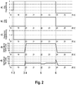
- the Figure 2 shows a schematic representation of different parameters of a vehicle during an exemplary implementation of the method.
- an anti-lock control is considered as a brake control function as an example.
- the top diagram a) shows the degradation state of an anti-lock control, which provides information about the operating mode in which the anti-lock control is.
- the activation state of the anti-lock control is shown in the second diagram b), with state 1 indicating activation of the anti-lock control.
- the degradation state of a wheel speed sensor is shown by way of example, that is, information about its operating mode.
- the fourth diagram d) shows the Course of a brake pressure requested by a vehicle driver by actuating the brake, while the fifth and lowest diagram e) shows the brake pressure actually present in a wheel brake.
- the five diagrams are plotted over a common, horizontal time axis.
- diagrams b) d) and e) begin with the value 0.
- the degradation state of the anti-lock control (diagram a)), as well as the degradation state of the wheel speed sensor (diagram c)), is 1 in the normal state.
- the degradation state of the anti-lock control (diagram a) is switched to a fallback mode, represented by level 4.
- this fallback mode provision can be made, for example, that when the anti-lock control is activated, a predefined deceleration torque is applied to the wheel affected by the failure of the wheel speed sensor.
- an ABS warning lamp in the vehicle can be activated, which informs the driver of the malfunction present.
- a timer is started which, in the present example, measures a period of 2.5 seconds after which the anti-lock control is to be deactivated.
- the vehicle driver actuates the vehicle brake or a corresponding brake pedal at time 3, so that the brake pressure requested by the vehicle driver in diagram d) increases.
- the brake pressure requested by the vehicle driver exceeds a locking pressure level at which the wheel locks.
- the anti-lock control is activated at this point in time, as shown in diagram b). Since the anti-lock control is in the fallback mode (diagram a)), the brake pressure and consequently the deceleration torque on the wheel affected by the failure are limited to a predefined value.
- the deactivation of the anti-lock control is delayed until its execution has been completed. As a result, the anti-lock brake control initially remains active.
- instability of the vehicle as a result of the braking process is determined at time 5, for example by monitoring the yaw angle of the vehicle.
- the brake pressure on the wheel concerned is automatically reduced until the vehicle is stable again.
- the brake pressure is then set back to the previously defined value.
- the vehicle driver released the brake so that the requested brake pressure drops.
- the brake pressure has fallen below the locking pressure level, so that the anti-lock control is deactivated (level 0 in diagram b)). Since the defined period of time has elapsed at this point and the anti-lock control is no longer active, the degradation level of the anti-lock control is switched to mode 0, which indicates that the function is no longer available, i.e. deactivated.
Landscapes
- Engineering & Computer Science (AREA)
- Mechanical Engineering (AREA)
- Transportation (AREA)
- Human Computer Interaction (AREA)
- Physics & Mathematics (AREA)
- Acoustics & Sound (AREA)
- Regulating Braking Force (AREA)
- Valves And Accessory Devices For Braking Systems (AREA)
Abstract
Description
- Die Erfindung betrifft ein Verfahren zur Steuerung eines Bremssystems eines Fahrzeugs.
- In modernen Fahrzeugen werden Fahrzeugführer durch eine Vielzahl von Fahrassistenzfunktion beim Führen des Fahrzeugs unterstützt. Bekannte Beispiele für derartige Fahrassistenzfunktion sind Antiblockiersysteme oder Stabilitätsprogramme, die ein durch den Fahrzeugführer angefordertes Verzögerungs- oder Beschleunigungsverhalten des Fahrzeugs so regeln, dass die Fahrstabilität des Fahrzeugs stets gewährleistet bleibt.
- Viele dieser Fahrassistenzfunktionen, insbesondere Funktionen, die sich auf eine Regelung eines Bremsverhaltens des Fahrzeugs beziehen (Bremsregelfunktionen), stützen sich auf eine Überwachung der Drehzahlen der Fahrzeugräder (Raddrehzahlen). So wird beispielsweise bei Antiblockiersystemen üblicherweise die Bremskraft an einem Fahrzeugrad reduziert, sobald die überwachten Raddrehzahlen darauf hinweisen, dass das Fahrzeugrad einen zu großen Schlupf aufweist.
- Bei einem Ausfall eines oder mehrerer Raddrehzahlsensoren ist üblicherweise vorgesehen, dass derartige Bremsregelfunktionen deaktiviert werden, da eine zuverlässige Regelung bei Fehlen der entsprechenden Raddrehzahlinformationen nicht oder nur eingeschränkt möglich ist.
- Wird ferner zum Zeitpunkt des Ausfalls eine Bremsregelfunktion durchgeführt, ist häufig vorgesehen, dass zumindest das vom Ausfall betroffene Rad sofort aus der Bremsregelfunktion ausgenommen wird. Dabei kann entweder vorgesehen sein, dass eine Bremsanforderung ungeregelt an das betroffene Rad weitergegeben wird, oder das betroffene Rad wird nicht mehr zur Verzögerung des Fahrzeugs angesteuert. Im ersten Fall kann ein Blockieren des betroffenen Rades nicht mehr effektiv verhindert werden, während im zweiten Fall die verfügbare Verzögerungsleistung deutlich reduziert wird.
- Das zuvor beschriebene Vorgehen kann insbesondere problematisch sein, wenn der Ausfall eines Raddrehzahlsensors auf einen Unfall des Fahrzeugs zurückzuführen ist. In diesem Fall wären nach dem Unfall Sicherheitsroutinen, die auf derartigen Bremsregelfunktionen aufbauen und die beispielsweise ein automatisches Bremsen nach dem Unfall umsetzen sollen (Post Crash Braking), nicht mehr verfügbar.
- Demgegenüber liegt der vorliegenden Erfindung die Aufgabe zugrunde, ein Verfahren zur Steuerung eines Bremssystems eines Fahrzeugs zu schaffen, das die vorstehend beschriebenen Nachteile überwindet und insbesondere die Verfügbarkeit und die Wirksamkeit von Bremsregelfunktionen bei einem Ausfall von entsprechenden Sensormitteln zur Bestimmung von Raddrehzahlen verbessert.
- Diese Aufgabe wird mit dem Verfahren gemäß Anspruch 1 gelöst. Vorteilhafte Ausgestaltungen der Erfindung sind Gegenstand der abhängigen Ansprüche.
- Die Erfindung betrifft ein Verfahren zur Steuerung eines Bremssystems eines Fahrzeugs, wobei das Bremssystem je Fahrzeugrad wenigstens eine Radbremse aufweist. Für die Radbremsen sind Sensormittel zur Bestimmung von Raddrehzahlen der Fahrzeugräder vorgesehen. Das Bremssystem ist dabei dazu ausgebildet, Bremsregelfunktionen auf Grundlage der durch die Sensormittel bestimmten Raddrehzahlen auszuführen. Das Verfahren weist dabei das Erkennen eines Ausfalls der Sensormittel für wenigstens eines der Fahrzeugräder und das Prüfen, ob zum Zeitpunkt des Ausfalls eine Bremsregelfunktion durch das Bremssystem ausgeführt wird, auf. Wenn zum Zeitpunkt des Ausfalls eine Bremsregelfunktion durch das Bremssystem ausgeführt wird, weist das Verfahren das Fortführen der Bremsregelfunktion und das Deaktivieren der Bremsregelfunktion, wenn die Ausführung der Bremsregelfunktion abgeschlossen ist, auf. Wenn zum Zeitpunkt des Ausfalls keine Bremsregelfunktion durch das Bremssystem ausgeführt wird, weist das Verfahren das Prüfen, ob innerhalb einer definierten Zeitspanne nach dem Zeitpunkt des Ausfalls eine Bremsregelfunktion ausgelöst wird, auf. Wenn innerhalb der definierten Zeitspanne nach dem Zeitpunkt des Ausfalls eine Bremsregelfunktion ausgelöst wird, sieht das Verfahren das Ausführen der Bremsregelfunktion vor. Ferner weist das Verfahren das Deaktivieren der Bremsenregelfunktion vor, wenn die Ausführung der Bremsregelfunktion abgeschlossen und die Zeitspanne abgelaufen ist, oder wenn innerhalb der definierten Zeitspanne nach dem Zeitpunkt des Ausfalls keine Bremsregelfunktion ausgelöst wurde.
- Unter einer "Bremsregelfunktion" ist dabei grundsätzlich eine Funktion zu verstehen, die ein durch die Radbremsen des Fahrzeugs erzeugtes Bremsmoment infolge einer Bremsanforderung in irgendeiner Form steuert oder regelt. Dabei kann die entsprechende Bremsanforderung sowohl durch einen Fahrzeugführer ausgelöst werden, als auch durch eine (teil)autonome Fahrfunktion, wie beispielsweise ein Autopilot oder Notbremsassistent. Beispielsweise kann es sich bei der Bremsregelfunktion um eine Funktion handeln, die nach Erkennen eines Unfalls des Fahrzeugs das Fahrzeug automatisch und vorzugsweise maximal möglichen Verzögerung zum Stillstand bringt. Eine solche Funktion kann dabei auch auf weitere Bremsregelfunktionen zurückgreifen, die beispielsweise eine maximale Verzögerung bei gleichbleibender Kontrollierbarkeit des Fahrzeugs gewährleisten sollen.
- Das erfindungsgemäße "Deaktivieren" einer Bremsregelfunktion bedeutet dabei, dass ab dem Zeitpunkt der Deaktivierung die entsprechende Bremsregelfunktion nicht mehr ausgelöst werden kann, also nicht mehr zur Verfügung steht. Dabei kann beispielsweise vorgesehen sein, dass die Deaktivierung so lange Bestand hat, bis durch einen entsprechenden Steuerbefehl die Bremsregelfunktion wieder aktiviert wird. Ein solcher Steuerbefehl könnte beispielsweise durch einen Mechaniker ausgelöst werden, sobald fehlerhafte Sensormittel ausgetauscht oder repariert wurden.
- Das erfindungsgemäße Verfahren hat dabei den Vorteil, dass trotz eines Ausfalls von Sensormitteln zur Bestimmung der Raddrehzahl die betroffenen Bremsregelfunktionen weiterhin zumindest für eine bestimmte Zeitspanne weiterhin verfügbar bleiben. Folglich kann beispielsweise nach einem Unfall noch für eine kurze Zeit eine Bremsregelfunktion, wie beispielsweise eine automatische Verzögerung des Fahrzeugs bis zu dessen Stillstand umgesetzt werden. Ferner steht beispielsweise nach einem Ausfall der betroffenen Sensormittel im laufenden (teil)automatisierten Fahrbetrieb ausreichend Zeit zur Verfügung, um den Fahrzeugführer über den Ausfall in Kenntnis zu setzen und eine sichere Übergabe der Kontrolle über das Fahrzeug an den Fahrzeugführer durchzuführen.
- Gleichzeitig ist vorgesehen, dass zum Zeitpunkt des Ausfalls bereits ausgeführte Bremsenregelfunktionen weiterhin ausgeführt werden und eine Deaktivierung der entsprechenden Bremsenregelfunktion erst erfolgt, wenn laufende Ausführung beendet wurde.
- Dabei ist nach einer weiteren Ausführungsform vorgesehen, dass es sich bei der Bremsenregelfunktion um eine Antiblockierregelung handelt, wobei nach Erkennen eines Ausfalls der Sensormittel für wenigstens eines der Fahrzeugräder beim Ausführen der Antiblockierregelung das Fahrzeugrad, für das der Ausfall der Sensormittel erkannt wurde, mit einem vordefinierten Verzögerungsmoment beaufschlagt wird. Unter einem "Verzögerungsmoment" ist dabei ein auf das Fahrzeugrad durch die Radbremse ausgeübtes Drehmoment zu verstehen, was zu einer Verlangsamung der Rotation des Fahrzeugrades führt. Das Verzögerungsmoment ist dabei vorzugsweise so gewählt, dass unter gegebenen Bedingungen zwar eine starke Verzögerung erreicht wird, jedoch kein Blockieren des verzögerten Rades zu befürchten ist. Beispielsweise kann das Verzögerungsmoment so gewählt sein, dass bei einer Beaufschlagung aller Radbremsen mit entsprechenden Verzögerungsmomenten unter Normalbedingungen, also beispielsweise bei trockener, asphaltierter Straße, eine Verzögerung des Fahrzeugs von 0,7g erreicht würde. Auf diese Weise wird gewährleistet, dass trotz eines Ausfalls der entsprechenden Sensormittel auch weiterhin ein gewisser Beitrag zur Gesamtverzögerung des Fahrzeugs durch die Radbremse jenes Rades geleistet wird, für das der Ausfall der Sensormittel erkannt wurde.
- Um bei der Ausführung einer Bremsregelfunktion nach Erkennen eines Ausfalls der Sensormittel für wenigstens eines der Fahrzeugräder weiterhin die Fahrstabilität des Fahrzeugs zu gewährleisten, ist nach einer weiteren Ausführungsform vorgesehen, dass bei erkanntem Ausfall der Sensormittel für wenigstens eines der Fahrzeugräder bei Ausführen der Bremsregelfunktion der Gierwinkel des Fahrzeugs überwacht wird, wobei bei Erkennung einer Änderung des Gierwinkels, der nicht einem Lenkbefehl eines Fahrzeugführers entspricht, die Radbremse des Fahrzeugrades, für das der Ausfall der Sensormittel erkannt wurde, zumindest teilweise gelöst wird.
- Dieser Ansatz beruht auf der Überlegung, dass bei einem einseitigen Überbremsen der Radbremsen, also einem erhöhten Schlupf an wenigstens einem der Räder einer Fahrzeugseite ein Giermoment entsteht, das durch eine entsprechende Sensorik erkannt werden kann. Sobald dabei ein Giermoment erkannt wird, das nicht mit einem Lenkbefehl des Fahrzeugführers übereinstimmt, ist von einem Blockieren eines der Räder infolge eines zu starken Verzögerungsmoments auszugehen. Dabei kann vorgesehen sein, dass bei Erkennen eines solchen Giermoments eine von dem Ausfall der Sensormittel betroffenes Rad vollständig entbremst wird, also die entsprechende Radbremse vollständig gelöst wird. Alternativ kann auch das Verzögerungsmoment an dem betroffenen Rad langsam reduziert werden, bis die Änderung des Gierwinkels wieder einem Lenkbefehl des Fahrzeugführers folgt.
- Nach einer weiteren Ausführungsform ist ferner vorgesehen, dass die Sensormittel wenigstens einen Raddrehzahlsensor pro Fahrzeugrad umfassen. Ferner kann auch vorgesehen sein, dass die Sensormittel redundant ausgelegt sind, also die Raddrehzahl jedes Fahrzeugrades durch wenigstens zwei Raddrehzahlsensoren überwacht wird.
- Nach einer weiteren Ausführungsform ist vorgesehen, dass die Dauer der definierten Zeitspanne zwischen 1 und 30 Sekunden, insbesondere zwischen 1 und 5 Sekunden, insbesondere 2,5 Sekunden beträgt.
- Zur Information Fahrzeugführers über einen erkannten Ausfall der Sensormittel ist nach einer weiteren Ausführungsform vorgesehen, dass bei erkanntem Ausfall der Sensormittel für wenigstens eines der Fahrzeugräder eine optische und/oder akustische Warnung an einen Fahrzeugführer ausgegeben wird. Insbesondere kann durch Aktivierung einer entsprechenden Leuchte in einem Armaturenbrett des Fahrzeugs auf einen erkannten Ausfall hingewiesen werden.
- Im Folgenden werden bevorzugte Ausgestaltungen der Erfindung anhand der Zeichnungen näher erläutert. Dabei zeigen:
- Figur 1
- ein Flussdiagramm einer beispielhaften Ausgestaltung des Verfahrens,
- Figur 2
- schematische Diagramme unterschiedlicher Parameter eines Fahrzeugs während einer beispielhaften Umsetzung des Verfahrens.
- Im Folgenden werden einander ähnliche oder identische Merkmale mit denselben Bezugszeichen gekennzeichnet.
- Die
Figur 1 zeigt eine schematische Darstellung einer beispielhaften Ausgestaltung des erfindungsgemäßen Verfahrens 100. Zur Implementierung des Verfahrens 100 ist dabei ein Bremssystem eines Fahrzeugs vorgesehen, wobei das Bremssystem je Fahrzeugrad wenigstens eine Radbremse aufweist, wobei für die Radbremsen Sensormittel zur Bestimmung von Raddrehzahlen der Fahrzeugräder vorgesehen sind, und wobei das Bremssystem dazu ausgebildet ist, Bremsregelfunktionen auf Grundlage der durch die Sensormittel bestimmten Raddrehzahlen auszuführen. Insbesondere kann dabei jedes Fahrzeugrad über einen radindividuellen Raddrehzahlsensor verfügen. - Dabei wird in einem ersten Verfahrensschritt 102 ein Ausfall der Sensormittel des Fahrzeugs für wenigstens eines der Fahrzeugräder erkannt. Ein derartiger Ausfall kann beispielsweise in einem Unfall des Fahrzeugs, oder in üblichen Abnutzungserscheinungen von Fahrzeugelementen begründet sein. Neben einem Ausfall eines Raddrehzahlsensors an sich, kann auch die Unterbrechung einer Datenverbindung zwischen dem Raddrehzahlsensor und einem Bremsensteuergerät als Ausfall der Sensormittel interpretiert werden, da auch in diesem Fall die notwendigen Informationen hinsichtlich der Drehzahl des betroffenen Fahrzeugrades nicht mehr zur Verfügung stehen.
- Nachdem in Schritt 102 der Ausfall der Sensormittel erkannt wurde, wird in Schritt 104 ein Timer gestartet, der eine vordefinierte Zeitspanne abmisst, beispielsweise eine Zeitspanne von 2,5 Sekunden.
- Anschließend wird in Schritt 106 geprüft, ob zum Zeitpunkt des Ausfalls eine Bremsregelfunktion, wie beispielsweise eine Antiblockierregelung, ausgeführt wird. Ist dies der Fall, wird die Bremsregelfunktion in Schritt 108 fortgeführt, bis die Ausführung der Bremsregelfunktion abgeschlossen ist, also beispielsweise das Fahrzeug zum Stillstand gekommen ist, oder eine entsprechende Bremsanforderung nicht mehr vorliegt. Bei einer Antiblockierregelung kann dabei vorgesehen sein, dass das von dem Ausfall der Sensormittel betroffene Rad mit einem vordefinierten Verzögerungsmoment beaufschlagt wird, das beispielsweise eine Fahrzeugverzögerung von 0,7g entspricht.
- Wird hingegen in Schritt 106 festgestellt, dass zum Zeitpunkt des Ausfalls keine Bremsregelfunktion ausgeführt wird, geht das Verfahren zu Schritt 110 über, in dem überprüft wird, ob der Timer abgelaufen, also die vordefinierte Zeitspanne verstrichen ist. Nach Abschluss der Ausführung der Bremsregelfunktion in Schritt 108 geht das Verfahren ebenfalls zu Schritt 110 über.
- Wird in Schritt 110 festgestellt, dass der Timer bereits abgelaufen ist, wird in Schritt 112 die Bremsregelfunktion deaktiviert und das Verfahren endet an dieser Stelle. Zusätzlich kann eine optische und/oder akustische Warnung an einen Fahrzeugführer ausgegeben werden, die auf einen Ausfall der Sensormittel oder die Deaktivierung der Bremsregelfunktion hinweisen.
- Wird hingegen in Schritt 110 festgestellt, dass der Timer noch nicht abgelaufen ist, wird anschließend in Schritt 114 geprüft, ob eine Bremsregelfunktion ausgelöst wurde. Eine Bremsregelfunktion kann dabei beispielsweise durch eine Betätigung der Fahrzeugbremse durch den Fahrzeugführer, oder durch eine (teil)autonome Fahrfunktion ausgelöst werden.
- Wird hierbei festgestellt, dass keine Bremsregelfunktion ausgelöst wurde, springt das Verfahren zurück zu Schritt 110, sodass effektiv eine fortlaufende Überwachung auf die Aktivierung von Bremsregelfunktionen ausgeführt wird, solange der Timer nicht abgelaufen ist.
- Wird in Schritt 114 hingegen festgestellt, dass eine Bremsregelfunktion ausgelöst wurde, wird anschließend in Schritt 116 die entsprechende Bremsregelfunktion ausgeführt. Wie zuvor bereits mit Bezug zu Schritt 108 ausgeführt wurde, wird die Ausführung der Bremsregelfunktion vorzugsweise so angepasst, dass die fehlenden Raddrehzahlinformationen des betroffenen Rades kompensiert werden. Sobald die Bremsregelfunktion aus Schritt 116 beendet wurde, springt das Verfahren wieder zurück zu Schritt 110, sodass weiterhin geprüft wird, ob der Timer abgelaufen, also die definierte Zeitspanne verstrichen ist.
- Folglich wird mit dem beschriebenen Verfahren eine Bremsregelfunktion infolge eines Ausfalls der Sensormittel für wenigstens eines der Fahrzeugräder erst dann deaktiviert, wenn eine definierte Zeitspanne abgelaufen ist und keine Bremsregelfunktionen mehr aktiv sind.
- Die
Figur 2 zeigt eine schematische Darstellung unterschiedlicher Parameter eines Fahrzeugs während einer beispielhaften Umsetzung des Verfahrens. Dabei wird beispielhaft eine Antiblockierregelung als Bremsregelfunktion betrachtet. - Dabei ist in dem obersten Diagramm a) der Degradierungszustand einer Antiblockierregelung dargestellt, der Auskunft darüber gibt, in welchem Betriebsmodus sich die Antiblockierregelung befindet. In dem zweiten Diagramm b) ist der Aktivierungszustand der Antiblockierregelung dargestellt, wobei der Zustand 1 eine Aktivierung der Antiblockierregelung anzeigt. In dem dritten Diagramm c) ist beispielhaft der Degradierungszustand eines Raddrehzahlsensors dargestellt, also eine Information über dessen Betriebsmodus. Das vierte Diagramm d) zeigt den Verlauf eines von einem Fahrzeugführer durch Betätigung der Bremse angeforderten Bremsdrucks, während das fünfte und unterste Diagramm e) den tatsächlich in einer Radbremse anliegenden Bremsdruck darstellt.
- Die fünf Diagramme sind dabei über einer gemeinsamen, horizontalen Zeitachse aufgetragen.
- Im Ausgangszustand liegt keine Bremsanforderung vor, sodass die Diagramme b) d) und e) bei dem Wert 0 beginnen. Der Degradierungszustand der Antiblockierregelung (Diagramm a)), wie auch der Degradierungszustand des Raddrehzahlsensors (Diagramm c)) ist im Normalzustand 1.
- Zum Zeitpunkt 1 tritt nun ein Fehler des betrachteten Raddrehzahlsensors auf, der durch eine entsprechende Überwachungsroutine jedoch noch nicht bestätigt wurde. Folglich springt der Degradierungszustand des Raddrehzahlsensors auf einen entsprechenden Betriebsmodus 2. Die übrigen Parameter bleiben zunächst unverändert.
- Zum Zeitpunkt 2 wurde der Fehler des Raddrehzahlsensors bestätigt, sodass der Degradierungszustand des Raddrehzahlsensors auf Stufe 0 springt, die anzeigt, dass der Raddrehzahlsensor nicht mehr verfügbar ist. Als Folge hiervon wird der Degradierungszustand der Antiblockierregelung (Diagramm a) in eine Rückfallbetriebsart geschaltet, dargestellt durch die Stufe 4. In dieser Rückfallbetriebsart kann beispielsweise vorgesehen sein, dass bei Aktivierung der Antiblockierregelung von dem Ausfall des Raddrehzahlsensors betroffene Rad mit einem vordefinierten Verzögerungsmoment beaufschlagt wird.
- Gleichzeitig kann eine ABS-Warnlampe des Fahrzeugs aktiviert werden, die den Fahrzeugführer auf die vorliegende Fehlfunktion hinweist. Zu diesem Zeitpunkt wird ein Timer gestartet, der in dem vorliegenden Beispiel eine Zeitspanne von 2,5 Sekunden abmisst, nach der die Antiblockierregelung deaktiviert werden soll.
- Innerhalb dieser Zeitspanne betätigt der Fahrzeugführer zum Zeitpunkt 3 die Fahrzeugbremse bzw. ein entsprechendes Bremspedal, sodass der durch den Fahrzeugführer angeforderte Bremsdruck in Diagramm d) ansteigt.
- Zum Zeitpunkt 4 übersteigt der von dem Fahrzeugführer angeforderte Bremsdruck ein Blockierdruckniveau, bei dem ein Blockieren des Rades auftritt. Folglich wird zu diesem Zeitpunkt die Antiblockierregelung aktiviert, wie in Diagramm b) angezeigt. Da die Antiblockierregelung in der Rückfallbetriebsart ist (Diagramm a)), wird der Bremsdruck und mithin das Verzögerungsmoment an dem von dem Ausfall betroffenen Rad auf einen vordefinierten Wert limitiert.
- Obwohl bei fortlaufender Antiblockierregelung die Zeitspanne von 2,5 Sekunden bereits verstrichen ist, wird die Deaktivierung der Antiblockierregelung verzögert, bis deren Ausführung abgeschlossen ist. Folglich bleibt die Antiblockierregelung zunächst weiterhin aktiv.
- Dabei wird zum Zeitpunkt 5 beispielsweise anhand einer Überwachung des Gierwinkel des Fahrzeugs eine Instabilität des Fahrzeugs infolge des Bremsvorgangs festgestellt. Als Folge hiervon wird automatisch der Bremsdruck an dem betroffenen Rad abgesenkt, bis das Fahrzeug wieder stabil ist. Anschließend wird der Bremsdruck wieder auf den zuvor festgelegten Wert eingestellt.
- Zum Zeitpunkt 6 hat der Fahrzeugführer die Bremse gelöst, sodass der angeforderte Bremsdruck abfällt. Dabei ist im Zeitpunkt 6 der Bremsdruck unter das Blockierdruckniveau gefallen, sodass die Antiblockierregelung deaktiviert wird (Stufe 0 in Diagramm b)). Da zu diesem Zeitpunkt die definierte Zeitspanne verstrichen ist und die Antiblockierregelung nicht mehr aktiv ist, wird die Degradierungsstufe der Antiblockierregelung auf den Modus 0 geschaltet, der anzeigt, dass die Funktion nicht mehr verfügbar, also deaktiviert ist.
Claims (6)
- Verfahren zur Steuerung eines Bremssystem eines Fahrzeugs, wobei das Bremssystem je Fahrzeugrad wenigstens eine Radbremse aufweist, wobei für die Radbremsen Sensormittel zur Bestimmung von Raddrehzahlen der Fahrzeugräder vorgesehen sind, und wobei das Bremssystem dazu ausgebildet ist, Bremsregelfunktionen auf Grundlage der durch die Sensormittel bestimmten Raddrehzahlen auszuführen, wobei das Verfahren die folgenden Schritte aufweist:• Erkennen eines Ausfalls der Sensormittel für wenigstens eines der Fahrzeugräder,• Prüfen, ob zum Zeitpunkt des Ausfalls eine Bremsregelfunktion durch das Bremssystem ausgeführt wird,• Wenn zum Zeitpunkt des Ausfalls eine Bremsregelfunktion durch das Bremssystem ausgeführt wird, Fortführen der Bremsregelfunktion und Deaktivieren der Bremsregelfunktion, wenn die Ausführung der Bremsregelfunktion abgeschlossen ist,• Wenn zum Zeitpunkt des Ausfalls keine Bremsregelfunktion durch das Bremssystem ausgeführt wird, Prüfen, ob innerhalb einer definierten Zeitspanne nach dem Zeitpunkt des Ausfalls eine Bremsregelfunktion ausgelöst wird,• Wenn innerhalb der definierten Zeitspanne nach dem Zeitpunkt des Ausfalls eine Bremsregelfunktion ausgelöst wird, Ausführen der Bremsregelfunktion und• Deaktivieren der Bremsenregelfunktion, wenn die Ausführung der Bremsregelfunktion abgeschlossen und die Zeitspanne abgelaufen ist, oder wenn innerhalb der definierten Zeitspanne nach dem Zeitpunkt des Ausfalls keine Bremsregelfunktion ausgelöst wurde.
- Verfahren nach Anspruch 1, dadurch gekennzeichnet, dass es sich bei der Bremsenregelfunktion um eine Antiblockierregelung handelt, wobei nach Erkennen eines Ausfalls der Sensormittel für wenigstens eines der Fahrzeugräder beim Ausführen der Antiblockierregelung, das Fahrzeugrad, für das der Ausfall der Sensormittel erkannt wurde, mit einem vordefinierten Verzögerungsmoment beaufschlagt wird.
- Verfahren nach Anspruch 1 oder 2, dadurch gekennzeichnet, dass bei erkanntem Ausfall der Sensormittel für wenigstens eines der Fahrzeugräder bei Ausführen der Bremsregelfunktion der Gierwinkel des Fahrzeugs überwacht wird, wobei bei Erkennung einer Änderung des Gierwinkels, der nicht einem Lenkbefehl eines Fahrzeugführers entspricht, die Radbremse des Fahrzeugrades, für das der Ausfall der Sensormittel erkannt wurde, zumindest teilweise gelöst wird.
- Verfahren nach einem der vorherigen Ansprüche, dadurch gekennzeichnet, dass die Sensormittel wenigstens einen Raddrehzahlsensor pro Fahrzeugrad umfassen.
- Verfahren nach einem der vorherigen Ansprüche, dadurch gekennzeichnet, dass die Dauer der definierten Zeitspanne zwischen 1 und 30 Sekunden, insbesondere zwischen 1 und 5 Sekunden, insbesondere 2,5 Sekunden beträgt.
- Verfahren nach einem der vorherigen Ansprüche, dadurch gekennzeichnet, dass bei erkanntem Ausfall der Sensormittel für wenigstens eines der Fahrzeugräder eine optische und/oder akustische Warnung an einen Fahrzeugführer ausgegeben wird.
Applications Claiming Priority (1)
| Application Number | Priority Date | Filing Date | Title |
|---|---|---|---|
| DE102019219328.5A DE102019219328A1 (de) | 2019-12-11 | 2019-12-11 | Verfahren zur Steuerung eines Bremssystems eines Fahrzeugs |
Publications (2)
| Publication Number | Publication Date |
|---|---|
| EP3835151A1 true EP3835151A1 (de) | 2021-06-16 |
| EP3835151B1 EP3835151B1 (de) | 2023-12-06 |
Family
ID=73014395
Family Applications (1)
| Application Number | Title | Priority Date | Filing Date |
|---|---|---|---|
| EP20203743.8A Active EP3835151B1 (de) | 2019-12-11 | 2020-10-26 | Verfahren zur steuerung eines bremssystems eines fahrzeugs |
Country Status (3)
| Country | Link |
|---|---|
| US (1) | US12024151B2 (de) |
| EP (1) | EP3835151B1 (de) |
| DE (1) | DE102019219328A1 (de) |
Families Citing this family (2)
| Publication number | Priority date | Publication date | Assignee | Title |
|---|---|---|---|---|
| DE102021108524A1 (de) * | 2021-04-06 | 2022-10-06 | Audi Aktiengesellschaft | Bremssystem für ein autonomes Fahrzeug |
| DE102022107335B3 (de) * | 2022-03-29 | 2023-07-20 | Daimler Truck AG | Verfahren und Vorrichtung zum Betrieb eines Fahrzeugs |
Citations (7)
| Publication number | Priority date | Publication date | Assignee | Title |
|---|---|---|---|---|
| DE19511161A1 (de) * | 1995-03-27 | 1996-10-02 | Bosch Gmbh Robert | Bremssystem für ein Kraftfahrzeug |
| US20070050107A1 (en) * | 2005-08-29 | 2007-03-01 | Hirohisa Tanaka | Apparatus for detecting anomaly of wheel speed sensors |
| DE102007046692A1 (de) * | 2007-09-28 | 2009-04-02 | Volkswagen Ag | Antiblockiersystem für ein Kraftfahrzeug |
| US20100013296A1 (en) * | 2008-07-16 | 2010-01-21 | Hydro-Aire, Inc. | Method of maintaining optimal braking and skid protection for a two-wheeled vehicle having a speed sensor failure on a single wheel |
| DE102014209162A1 (de) * | 2014-05-14 | 2015-11-19 | Continental Teves Ag & Co. Ohg | Verfahren und Vorrichtung zur Steuerung einer Bremsanlage eines Kraftfahrzeuges |
| US20160272180A1 (en) * | 2015-03-19 | 2016-09-22 | Toyota Jidosha Kabushiki Kaisha | Abnormality information generating apparatus and vehicle control system |
| DE102017012110A1 (de) * | 2017-12-28 | 2019-07-04 | Lucas Automotive Gmbh | Einrichtung zur Bremsdruckberechnung |
Family Cites Families (6)
| Publication number | Priority date | Publication date | Assignee | Title |
|---|---|---|---|---|
| JP4293138B2 (ja) * | 2005-02-03 | 2009-07-08 | トヨタ自動車株式会社 | 内燃機関の制御装置及びその制御装置を備えた自動車 |
| DE102008042962A1 (de) * | 2008-10-20 | 2010-04-22 | Robert Bosch Gmbh | Verfahren zur Einstellung eines Bremssystems eines Fahrzeugs |
| DE102012202467A1 (de) * | 2012-02-17 | 2013-08-22 | Continental Teves Ag & Co. Ohg | Verfahren zur Ansteuerung eines Bremssystems, Bremssystem und Verwendung |
| DE102012209519B4 (de) * | 2012-06-06 | 2015-01-08 | Saf-Holland Gmbh | Verfahren zur Sicherstellung der Bremswirkung einer Bremse |
| DE102016005317A1 (de) * | 2016-05-02 | 2017-11-02 | Wabco Gmbh | Verfahren zum automatisierten elektronischen Steuern eines Bremssystems sowie elektronisch steuerbares Bremssystem in einem Nutzfahrzeug |
| DE102017012130A1 (de) * | 2017-12-28 | 2019-07-04 | Lucas Automotive Gmbh | Signalverarbeitungsvorrichtung für ein Fahrzeug mit einer Antiblockier-Einrichtung |
-
2019
- 2019-12-11 DE DE102019219328.5A patent/DE102019219328A1/de not_active Withdrawn
-
2020
- 2020-10-26 EP EP20203743.8A patent/EP3835151B1/de active Active
- 2020-12-10 US US17/117,349 patent/US12024151B2/en active Active
Patent Citations (7)
| Publication number | Priority date | Publication date | Assignee | Title |
|---|---|---|---|---|
| DE19511161A1 (de) * | 1995-03-27 | 1996-10-02 | Bosch Gmbh Robert | Bremssystem für ein Kraftfahrzeug |
| US20070050107A1 (en) * | 2005-08-29 | 2007-03-01 | Hirohisa Tanaka | Apparatus for detecting anomaly of wheel speed sensors |
| DE102007046692A1 (de) * | 2007-09-28 | 2009-04-02 | Volkswagen Ag | Antiblockiersystem für ein Kraftfahrzeug |
| US20100013296A1 (en) * | 2008-07-16 | 2010-01-21 | Hydro-Aire, Inc. | Method of maintaining optimal braking and skid protection for a two-wheeled vehicle having a speed sensor failure on a single wheel |
| DE102014209162A1 (de) * | 2014-05-14 | 2015-11-19 | Continental Teves Ag & Co. Ohg | Verfahren und Vorrichtung zur Steuerung einer Bremsanlage eines Kraftfahrzeuges |
| US20160272180A1 (en) * | 2015-03-19 | 2016-09-22 | Toyota Jidosha Kabushiki Kaisha | Abnormality information generating apparatus and vehicle control system |
| DE102017012110A1 (de) * | 2017-12-28 | 2019-07-04 | Lucas Automotive Gmbh | Einrichtung zur Bremsdruckberechnung |
Also Published As
| Publication number | Publication date |
|---|---|
| EP3835151B1 (de) | 2023-12-06 |
| US12024151B2 (en) | 2024-07-02 |
| US20210179045A1 (en) | 2021-06-17 |
| DE102019219328A1 (de) | 2021-06-17 |
Similar Documents
| Publication | Publication Date | Title |
|---|---|---|
| EP3044056B1 (de) | Fahrassistenzsystem mit gesteigerter ausfallsicherheit und verfügbarkeit | |
| EP1638824B1 (de) | Verfahren und vorrichtung zur deaktivierung einer hillholderfunktion | |
| EP2603406B1 (de) | Verfahren zum absichern einer elektrisch betätigten feststellbremse | |
| WO2009065754A2 (de) | Verfahren zur ansteuerung von zumindest einer elektromechanischen parkbremseneinheit eines elektromechanischen parkbremssystems | |
| WO2017102266A1 (de) | Verfahren zum betreiben eines kraftfahrzeugs, steuergerät für ein bremssystem und bremssystem für ein kraftfahrzeug | |
| DE112017002954B4 (de) | Fahrzeugbremskraftsteuereinrichtung | |
| DE102017000954A1 (de) | System, Verfahren, Computerprogramm und Steuergerät zum Verhindern eines Wegrollens eines Fahrzeugs | |
| EP0892732A1 (de) | Verfahren und vorrichtung zur steuerung der bremskraftverteilung bei einem kraftfahrzeug | |
| WO2017050406A1 (de) | Verfahren zum einstellen von bremsdrücken eines kraftfahrzeugs, bremsanlage zur durchführung des verfahrens sowie kraftfahrzeug | |
| DE10026687A1 (de) | Verfahren und Vorrichtung zur Wirkungsüberwachung von Fahrzeugbremsanlagen | |
| EP3835151B1 (de) | Verfahren zur steuerung eines bremssystems eines fahrzeugs | |
| EP3300974A1 (de) | Verfahren und vorrichtung zum steuern einer bremsanlage für ein fahrzeug, bremsanlage und fahrzeug | |
| WO2021204506A2 (de) | Systemeinheit mit einem ersten aktorsystem und einem zweiten aktorsystem | |
| DE19946482A1 (de) | Bremssteuervorrichtung | |
| DE102018219052A1 (de) | Berechnungs- und Aktuationsstrategie von fahrstabilisierenden Eingriffen | |
| EP1564096B1 (de) | Überprüfung der Funktionsfähigkeit einer Feststellbremse durch Auswertung der Raddrehzahlen | |
| EP3468849B1 (de) | Verfahren zum überwachen einer abs-regelung in einem elektrisch steuerbaren bremssystem sowie elektronisch steuerbares bremssystem | |
| AT526381B1 (de) | Verfahren zum Verringern einer Wegrollgeschwindigkeit einer fahrbaren, einen elektrischen Antriebsmotor umfassenden Maschine | |
| EP4200173B1 (de) | Verfahren zum sichern eines fahrzeugs | |
| DE3429156A1 (de) | Verfahren und schaltungsanordnung zur ueberwachung und steuerung einer schlupfgeregelten bremsanlage | |
| DE102009008958A1 (de) | Verfahren und Vorrichtung zum Stabilisieren eines Fahrzeugs | |
| EP4448358B1 (de) | Antriebsvorrichtung für ein fahrzeug | |
| WO2019110184A1 (de) | Verfahren zum betreiben einer lenkvorrichtung und lenkvorrichtung | |
| DE102022203749A1 (de) | Steuervorrichtung für ein elektrisches Antriebssystem, Bremssystem und Verfahren zur Steuerung eines elektrischen Antriebssystems | |
| EP4599417A1 (de) | Verfahren zum betreiben eines fahrzeugs mit x-by-wire-einrichtung unter verwendung eines flotten-watchdogs und fahrzeug |
Legal Events
| Date | Code | Title | Description |
|---|---|---|---|
| PUAI | Public reference made under article 153(3) epc to a published international application that has entered the european phase |
Free format text: ORIGINAL CODE: 0009012 |
|
| STAA | Information on the status of an ep patent application or granted ep patent |
Free format text: STATUS: THE APPLICATION HAS BEEN PUBLISHED |
|
| AK | Designated contracting states |
Kind code of ref document: A1 Designated state(s): AL AT BE BG CH CY CZ DE DK EE ES FI FR GB GR HR HU IE IS IT LI LT LU LV MC MK MT NL NO PL PT RO RS SE SI SK SM TR |
|
| STAA | Information on the status of an ep patent application or granted ep patent |
Free format text: STATUS: REQUEST FOR EXAMINATION WAS MADE |
|
| 17P | Request for examination filed |
Effective date: 20211216 |
|
| RBV | Designated contracting states (corrected) |
Designated state(s): AL AT BE BG CH CY CZ DE DK EE ES FI FR GB GR HR HU IE IS IT LI LT LU LV MC MK MT NL NO PL PT RO RS SE SI SK SM TR |
|
| RAP1 | Party data changed (applicant data changed or rights of an application transferred) |
Owner name: CONTINENTAL AUTOMOTIVE TECHNOLOGIES GMBH |
|
| GRAP | Despatch of communication of intention to grant a patent |
Free format text: ORIGINAL CODE: EPIDOSNIGR1 |
|
| STAA | Information on the status of an ep patent application or granted ep patent |
Free format text: STATUS: GRANT OF PATENT IS INTENDED |
|
| INTG | Intention to grant announced |
Effective date: 20230712 |
|
| GRAS | Grant fee paid |
Free format text: ORIGINAL CODE: EPIDOSNIGR3 |
|
| GRAA | (expected) grant |
Free format text: ORIGINAL CODE: 0009210 |
|
| STAA | Information on the status of an ep patent application or granted ep patent |
Free format text: STATUS: THE PATENT HAS BEEN GRANTED |
|
| AK | Designated contracting states |
Kind code of ref document: B1 Designated state(s): AL AT BE BG CH CY CZ DE DK EE ES FI FR GB GR HR HU IE IS IT LI LT LU LV MC MK MT NL NO PL PT RO RS SE SI SK SM TR |
|
| REG | Reference to a national code |
Ref country code: GB Ref legal event code: FG4D Free format text: NOT ENGLISH |
|
| REG | Reference to a national code |
Ref country code: CH Ref legal event code: EP |
|
| REG | Reference to a national code |
Ref country code: DE Ref legal event code: R096 Ref document number: 502020006289 Country of ref document: DE |
|
| REG | Reference to a national code |
Ref country code: IE Ref legal event code: FG4D Free format text: LANGUAGE OF EP DOCUMENT: GERMAN |
|
| REG | Reference to a national code |
Ref country code: DE Ref legal event code: R081 Ref document number: 502020006289 Country of ref document: DE Owner name: CONTINENTAL AUTOMOTIVE TECHNOLOGIES GMBH, DE Free format text: FORMER OWNER: CONTINENTAL AUTOMOTIVE TECHNOLOGIES GMBH, 30165 HANNOVER, DE Ref country code: DE Ref legal event code: R081 Ref document number: 502020006289 Country of ref document: DE Owner name: AUMOVIO GERMANY GMBH, DE Free format text: FORMER OWNER: CONTINENTAL AUTOMOTIVE TECHNOLOGIES GMBH, 30165 HANNOVER, DE |
|
| REG | Reference to a national code |
Ref country code: LT Ref legal event code: MG9D |
|
| PG25 | Lapsed in a contracting state [announced via postgrant information from national office to epo] |
Ref country code: GR Free format text: LAPSE BECAUSE OF FAILURE TO SUBMIT A TRANSLATION OF THE DESCRIPTION OR TO PAY THE FEE WITHIN THE PRESCRIBED TIME-LIMIT Effective date: 20240307 |
|
| REG | Reference to a national code |
Ref country code: NL Ref legal event code: MP Effective date: 20231206 |
|
| PG25 | Lapsed in a contracting state [announced via postgrant information from national office to epo] |
Ref country code: LT Free format text: LAPSE BECAUSE OF FAILURE TO SUBMIT A TRANSLATION OF THE DESCRIPTION OR TO PAY THE FEE WITHIN THE PRESCRIBED TIME-LIMIT Effective date: 20231206 |
|
| RAP4 | Party data changed (patent owner data changed or rights of a patent transferred) |
Owner name: CONTINENTAL AUTOMOTIVE TECHNOLOGIES GMBH |
|
| PG25 | Lapsed in a contracting state [announced via postgrant information from national office to epo] |
Ref country code: ES Free format text: LAPSE BECAUSE OF FAILURE TO SUBMIT A TRANSLATION OF THE DESCRIPTION OR TO PAY THE FEE WITHIN THE PRESCRIBED TIME-LIMIT Effective date: 20231206 |
|
| PG25 | Lapsed in a contracting state [announced via postgrant information from national office to epo] |
Ref country code: LT Free format text: LAPSE BECAUSE OF FAILURE TO SUBMIT A TRANSLATION OF THE DESCRIPTION OR TO PAY THE FEE WITHIN THE PRESCRIBED TIME-LIMIT Effective date: 20231206 Ref country code: GR Free format text: LAPSE BECAUSE OF FAILURE TO SUBMIT A TRANSLATION OF THE DESCRIPTION OR TO PAY THE FEE WITHIN THE PRESCRIBED TIME-LIMIT Effective date: 20240307 Ref country code: ES Free format text: LAPSE BECAUSE OF FAILURE TO SUBMIT A TRANSLATION OF THE DESCRIPTION OR TO PAY THE FEE WITHIN THE PRESCRIBED TIME-LIMIT Effective date: 20231206 Ref country code: BG Free format text: LAPSE BECAUSE OF FAILURE TO SUBMIT A TRANSLATION OF THE DESCRIPTION OR TO PAY THE FEE WITHIN THE PRESCRIBED TIME-LIMIT Effective date: 20240306 |
|
| REG | Reference to a national code |
Ref country code: CH Ref legal event code: PK Free format text: DIE PUBLIKATION VOM 27.03.2024 WURDE AM 24.04.2024 IRRTUEMLICHERWEISE ERNEUT PUBLIZIERT. LA PUBLICATION DU 27.03.2024 A ETE REPUBLIEE PAR ERREUR LE 24.04.2024. LA PUBBLICAZIONE DEL 27.03.2024 E STATA ERRONEAMENTE RIPUBBLICATA IL 24.04.2024. |
|
| PG25 | Lapsed in a contracting state [announced via postgrant information from national office to epo] |
Ref country code: NL Free format text: LAPSE BECAUSE OF FAILURE TO SUBMIT A TRANSLATION OF THE DESCRIPTION OR TO PAY THE FEE WITHIN THE PRESCRIBED TIME-LIMIT Effective date: 20231206 |
|
| PG25 | Lapsed in a contracting state [announced via postgrant information from national office to epo] |
Ref country code: SE Free format text: LAPSE BECAUSE OF FAILURE TO SUBMIT A TRANSLATION OF THE DESCRIPTION OR TO PAY THE FEE WITHIN THE PRESCRIBED TIME-LIMIT Effective date: 20231206 Ref country code: RS Free format text: LAPSE BECAUSE OF FAILURE TO SUBMIT A TRANSLATION OF THE DESCRIPTION OR TO PAY THE FEE WITHIN THE PRESCRIBED TIME-LIMIT Effective date: 20231206 Ref country code: NO Free format text: LAPSE BECAUSE OF FAILURE TO SUBMIT A TRANSLATION OF THE DESCRIPTION OR TO PAY THE FEE WITHIN THE PRESCRIBED TIME-LIMIT Effective date: 20240306 Ref country code: NL Free format text: LAPSE BECAUSE OF FAILURE TO SUBMIT A TRANSLATION OF THE DESCRIPTION OR TO PAY THE FEE WITHIN THE PRESCRIBED TIME-LIMIT Effective date: 20231206 Ref country code: LV Free format text: LAPSE BECAUSE OF FAILURE TO SUBMIT A TRANSLATION OF THE DESCRIPTION OR TO PAY THE FEE WITHIN THE PRESCRIBED TIME-LIMIT Effective date: 20231206 Ref country code: HR Free format text: LAPSE BECAUSE OF FAILURE TO SUBMIT A TRANSLATION OF THE DESCRIPTION OR TO PAY THE FEE WITHIN THE PRESCRIBED TIME-LIMIT Effective date: 20231206 |
|
| PG25 | Lapsed in a contracting state [announced via postgrant information from national office to epo] |
Ref country code: IS Free format text: LAPSE BECAUSE OF FAILURE TO SUBMIT A TRANSLATION OF THE DESCRIPTION OR TO PAY THE FEE WITHIN THE PRESCRIBED TIME-LIMIT Effective date: 20240406 |
|
| PG25 | Lapsed in a contracting state [announced via postgrant information from national office to epo] |
Ref country code: CZ Free format text: LAPSE BECAUSE OF FAILURE TO SUBMIT A TRANSLATION OF THE DESCRIPTION OR TO PAY THE FEE WITHIN THE PRESCRIBED TIME-LIMIT Effective date: 20231206 |
|
| PG25 | Lapsed in a contracting state [announced via postgrant information from national office to epo] |
Ref country code: SK Free format text: LAPSE BECAUSE OF FAILURE TO SUBMIT A TRANSLATION OF THE DESCRIPTION OR TO PAY THE FEE WITHIN THE PRESCRIBED TIME-LIMIT Effective date: 20231206 |
|
| PG25 | Lapsed in a contracting state [announced via postgrant information from national office to epo] |
Ref country code: SM Free format text: LAPSE BECAUSE OF FAILURE TO SUBMIT A TRANSLATION OF THE DESCRIPTION OR TO PAY THE FEE WITHIN THE PRESCRIBED TIME-LIMIT Effective date: 20231206 Ref country code: SK Free format text: LAPSE BECAUSE OF FAILURE TO SUBMIT A TRANSLATION OF THE DESCRIPTION OR TO PAY THE FEE WITHIN THE PRESCRIBED TIME-LIMIT Effective date: 20231206 Ref country code: RO Free format text: LAPSE BECAUSE OF FAILURE TO SUBMIT A TRANSLATION OF THE DESCRIPTION OR TO PAY THE FEE WITHIN THE PRESCRIBED TIME-LIMIT Effective date: 20231206 Ref country code: IT Free format text: LAPSE BECAUSE OF FAILURE TO SUBMIT A TRANSLATION OF THE DESCRIPTION OR TO PAY THE FEE WITHIN THE PRESCRIBED TIME-LIMIT Effective date: 20231206 Ref country code: IS Free format text: LAPSE BECAUSE OF FAILURE TO SUBMIT A TRANSLATION OF THE DESCRIPTION OR TO PAY THE FEE WITHIN THE PRESCRIBED TIME-LIMIT Effective date: 20240406 Ref country code: EE Free format text: LAPSE BECAUSE OF FAILURE TO SUBMIT A TRANSLATION OF THE DESCRIPTION OR TO PAY THE FEE WITHIN THE PRESCRIBED TIME-LIMIT Effective date: 20231206 Ref country code: CZ Free format text: LAPSE BECAUSE OF FAILURE TO SUBMIT A TRANSLATION OF THE DESCRIPTION OR TO PAY THE FEE WITHIN THE PRESCRIBED TIME-LIMIT Effective date: 20231206 |
|
| PG25 | Lapsed in a contracting state [announced via postgrant information from national office to epo] |
Ref country code: PL Free format text: LAPSE BECAUSE OF FAILURE TO SUBMIT A TRANSLATION OF THE DESCRIPTION OR TO PAY THE FEE WITHIN THE PRESCRIBED TIME-LIMIT Effective date: 20231206 Ref country code: PT Free format text: LAPSE BECAUSE OF FAILURE TO SUBMIT A TRANSLATION OF THE DESCRIPTION OR TO PAY THE FEE WITHIN THE PRESCRIBED TIME-LIMIT Effective date: 20240408 |
|
| PG25 | Lapsed in a contracting state [announced via postgrant information from national office to epo] |
Ref country code: PT Free format text: LAPSE BECAUSE OF FAILURE TO SUBMIT A TRANSLATION OF THE DESCRIPTION OR TO PAY THE FEE WITHIN THE PRESCRIBED TIME-LIMIT Effective date: 20240408 Ref country code: PL Free format text: LAPSE BECAUSE OF FAILURE TO SUBMIT A TRANSLATION OF THE DESCRIPTION OR TO PAY THE FEE WITHIN THE PRESCRIBED TIME-LIMIT Effective date: 20231206 |
|
| REG | Reference to a national code |
Ref country code: DE Ref legal event code: R097 Ref document number: 502020006289 Country of ref document: DE |
|
| PG25 | Lapsed in a contracting state [announced via postgrant information from national office to epo] |
Ref country code: DK Free format text: LAPSE BECAUSE OF FAILURE TO SUBMIT A TRANSLATION OF THE DESCRIPTION OR TO PAY THE FEE WITHIN THE PRESCRIBED TIME-LIMIT Effective date: 20231206 |
|
| PLBE | No opposition filed within time limit |
Free format text: ORIGINAL CODE: 0009261 |
|
| STAA | Information on the status of an ep patent application or granted ep patent |
Free format text: STATUS: NO OPPOSITION FILED WITHIN TIME LIMIT |
|
| PG25 | Lapsed in a contracting state [announced via postgrant information from national office to epo] |
Ref country code: SI Free format text: LAPSE BECAUSE OF FAILURE TO SUBMIT A TRANSLATION OF THE DESCRIPTION OR TO PAY THE FEE WITHIN THE PRESCRIBED TIME-LIMIT Effective date: 20231206 |
|
| PG25 | Lapsed in a contracting state [announced via postgrant information from national office to epo] |
Ref country code: SI Free format text: LAPSE BECAUSE OF FAILURE TO SUBMIT A TRANSLATION OF THE DESCRIPTION OR TO PAY THE FEE WITHIN THE PRESCRIBED TIME-LIMIT Effective date: 20231206 Ref country code: DK Free format text: LAPSE BECAUSE OF FAILURE TO SUBMIT A TRANSLATION OF THE DESCRIPTION OR TO PAY THE FEE WITHIN THE PRESCRIBED TIME-LIMIT Effective date: 20231206 |
|
| 26N | No opposition filed |
Effective date: 20240909 |
|
| REG | Reference to a national code |
Ref country code: CH Ref legal event code: PL |
|
| GBPC | Gb: european patent ceased through non-payment of renewal fee |
Effective date: 20241026 |
|
| PG25 | Lapsed in a contracting state [announced via postgrant information from national office to epo] |
Ref country code: MC Free format text: LAPSE BECAUSE OF FAILURE TO SUBMIT A TRANSLATION OF THE DESCRIPTION OR TO PAY THE FEE WITHIN THE PRESCRIBED TIME-LIMIT Effective date: 20231206 |
|
| PG25 | Lapsed in a contracting state [announced via postgrant information from national office to epo] |
Ref country code: GB Free format text: LAPSE BECAUSE OF NON-PAYMENT OF DUE FEES Effective date: 20241026 |
|
| PG25 | Lapsed in a contracting state [announced via postgrant information from national office to epo] |
Ref country code: BE Free format text: LAPSE BECAUSE OF NON-PAYMENT OF DUE FEES Effective date: 20241031 Ref country code: LU Free format text: LAPSE BECAUSE OF NON-PAYMENT OF DUE FEES Effective date: 20241026 |
|
| PG25 | Lapsed in a contracting state [announced via postgrant information from national office to epo] |
Ref country code: CH Free format text: LAPSE BECAUSE OF NON-PAYMENT OF DUE FEES Effective date: 20241031 |
|
| REG | Reference to a national code |
Ref country code: BE Ref legal event code: MM Effective date: 20241031 |
|
| PG25 | Lapsed in a contracting state [announced via postgrant information from national office to epo] |
Ref country code: FI Free format text: LAPSE BECAUSE OF FAILURE TO SUBMIT A TRANSLATION OF THE DESCRIPTION OR TO PAY THE FEE WITHIN THE PRESCRIBED TIME-LIMIT Effective date: 20231207 |
|
| PG25 | Lapsed in a contracting state [announced via postgrant information from national office to epo] |
Ref country code: IE Free format text: LAPSE BECAUSE OF NON-PAYMENT OF DUE FEES Effective date: 20241026 |
|
| PGFP | Annual fee paid to national office [announced via postgrant information from national office to epo] |
Ref country code: DE Payment date: 20251031 Year of fee payment: 6 |
|
| PGFP | Annual fee paid to national office [announced via postgrant information from national office to epo] |
Ref country code: AT Payment date: 20260113 Year of fee payment: 5 |
|
| PGFP | Annual fee paid to national office [announced via postgrant information from national office to epo] |
Ref country code: FR Payment date: 20251027 Year of fee payment: 6 |
|
| REG | Reference to a national code |
Ref country code: DE Ref legal event code: R081 Ref document number: 502020006289 Country of ref document: DE Owner name: AUMOVIO GERMANY GMBH, DE Free format text: FORMER OWNER: CONTINENTAL AUTOMOTIVE TECHNOLOGIES GMBH, 30175 HANNOVER, DE |
|
| PG25 | Lapsed in a contracting state [announced via postgrant information from national office to epo] |
Ref country code: CY Free format text: LAPSE BECAUSE OF FAILURE TO SUBMIT A TRANSLATION OF THE DESCRIPTION OR TO PAY THE FEE WITHIN THE PRESCRIBED TIME-LIMIT; INVALID AB INITIO Effective date: 20201026 |
|
| PG25 | Lapsed in a contracting state [announced via postgrant information from national office to epo] |
Ref country code: HU Free format text: LAPSE BECAUSE OF FAILURE TO SUBMIT A TRANSLATION OF THE DESCRIPTION OR TO PAY THE FEE WITHIN THE PRESCRIBED TIME-LIMIT; INVALID AB INITIO Effective date: 20201026 |