EP3835138B1 - Improvements relating to airbags - Google Patents
Improvements relating to airbags Download PDFInfo
- Publication number
- EP3835138B1 EP3835138B1 EP20212829.4A EP20212829A EP3835138B1 EP 3835138 B1 EP3835138 B1 EP 3835138B1 EP 20212829 A EP20212829 A EP 20212829A EP 3835138 B1 EP3835138 B1 EP 3835138B1
- Authority
- EP
- European Patent Office
- Prior art keywords
- mounting
- vehicle
- airbag
- cushion
- mounting member
- Prior art date
- Legal status (The legal status is an assumption and is not a legal conclusion. Google has not performed a legal analysis and makes no representation as to the accuracy of the status listed.)
- Active
Links
Images


Classifications
-
- B—PERFORMING OPERATIONS; TRANSPORTING
- B60—VEHICLES IN GENERAL
- B60R—VEHICLES, VEHICLE FITTINGS, OR VEHICLE PARTS, NOT OTHERWISE PROVIDED FOR
- B60R21/00—Arrangements or fittings on vehicles for protecting or preventing injuries to occupants or pedestrians in case of accidents or other traffic risks
- B60R21/02—Occupant safety arrangements or fittings, e.g. crash pads
- B60R21/16—Inflatable occupant restraints or confinements designed to inflate upon impact or impending impact, e.g. air bags
- B60R21/23—Inflatable members
- B60R21/231—Inflatable members characterised by their shape, construction or spatial configuration
-
- B—PERFORMING OPERATIONS; TRANSPORTING
- B60—VEHICLES IN GENERAL
- B60R—VEHICLES, VEHICLE FITTINGS, OR VEHICLE PARTS, NOT OTHERWISE PROVIDED FOR
- B60R21/00—Arrangements or fittings on vehicles for protecting or preventing injuries to occupants or pedestrians in case of accidents or other traffic risks
- B60R21/02—Occupant safety arrangements or fittings, e.g. crash pads
- B60R21/16—Inflatable occupant restraints or confinements designed to inflate upon impact or impending impact, e.g. air bags
- B60R21/20—Arrangements for storing inflatable members in their non-use or deflated condition; Arrangement or mounting of air bag modules or components
- B60R21/213—Arrangements for storing inflatable members in their non-use or deflated condition; Arrangement or mounting of air bag modules or components in vehicle roof frames or pillars
-
- B—PERFORMING OPERATIONS; TRANSPORTING
- B60—VEHICLES IN GENERAL
- B60R—VEHICLES, VEHICLE FITTINGS, OR VEHICLE PARTS, NOT OTHERWISE PROVIDED FOR
- B60R21/00—Arrangements or fittings on vehicles for protecting or preventing injuries to occupants or pedestrians in case of accidents or other traffic risks
- B60R21/02—Occupant safety arrangements or fittings, e.g. crash pads
- B60R21/16—Inflatable occupant restraints or confinements designed to inflate upon impact or impending impact, e.g. air bags
- B60R21/23—Inflatable members
-
- B—PERFORMING OPERATIONS; TRANSPORTING
- B60—VEHICLES IN GENERAL
- B60R—VEHICLES, VEHICLE FITTINGS, OR VEHICLE PARTS, NOT OTHERWISE PROVIDED FOR
- B60R21/00—Arrangements or fittings on vehicles for protecting or preventing injuries to occupants or pedestrians in case of accidents or other traffic risks
- B60R21/02—Occupant safety arrangements or fittings, e.g. crash pads
- B60R21/16—Inflatable occupant restraints or confinements designed to inflate upon impact or impending impact, e.g. air bags
- B60R21/23—Inflatable members
- B60R21/231—Inflatable members characterised by their shape, construction or spatial configuration
- B60R21/232—Curtain-type airbags deploying mainly in a vertical direction from their top edge
Definitions
- the present invention relates to vehicle curtain airbags. Aspects of the invention relate to a vehicle airbag, to a vehicle, and to a method of manufacturing a vehicle airbag.
- Airbags are inflatable restraints commonly used in passenger vehicles to restrain occupants within an occupant compartment of the vehicle in the event of a collision, rollover incident, or the like.
- An airbag comprises an inflatable cushion made from a flexible material defining at least one internal chamber into which pressurised gas is introduced when the airbag is deployed.
- the inflated airbag provides an energy absorbing layer between an occupant and a rigid component of the vehicle, dissipating the forces experienced by the occupant.
- Curtain airbags are used to provide an energy absorbing layer between the side windows of a vehicle and its occupants in the event of a side impact or rollover incident.
- curtain airbags are mounted in pairs inside the vehicle adjacent to the roof, one on either side of an occupant compartment.
- curtain airbags may have a number of mounting tabs spaced along an upper edge of the airbag cushion, each tab having an aperture.
- a screw threaded fastener such as a bolt is inserted though the aperture to engage in a threaded aperture in the vehicle body, typically provided by a nut welded to the vehicle body.
- a mounting formation such as a hook may be affixed to the vehicle body and engaged through the aperture.
- the mounting regions are often reinforced, either by folding the material of the airbag cushion over and stitching to form a double thickness; or by sewing a reinforcing material to the airbag cushion material. In either case, this is a skilled operation with many potential failure modes in the manufacturing process.
- US2005/098996A1 discloses a unitary plastic sleeve 52 which facilitates attachment of an inflatable chamber 50 for a knee bolster pad 12b to a receiving bracket 54 by a total of 16 bolts.
- aspects of the invention relate to a vehicle curtain airbag; to a vehicle; and to a method of manufacturing a vehicle airbag.
- a vehicle curtain airbag comprising an inflatable cushion made from flexible material defining at least one internal chamber, the material also defining a mounting region for attachment of the airbag cushion to a fixing point in a vehicle, characterized in that: a plurality of polymeric mounting members are moulded to the material of the airbag cushion within at least two of the mounting regions; wherein at least one polymeric mounting member is profiled to fit against or within a feature of a vehicle cant rail to which it is to be assembled in use.
- Moulding a polymeric mounting member to the airbag cushion material reinforces the material in the mounting region without the need for stitching.
- At least one mounting member may comprise a mounting bush.
- the mounting bush may define a through bore.
- the mounting bush may be adapted to enable a threaded fastener such as a bolt to be inserted through the bore for engagement with a threaded aperture in the vehicle fixing point.
- An aperture may be defined in the mounting region in alignment with the through bore.
- the mounting bush may comprise a body portion which extends through the aperture; and flange portions which project radially outwardly at either end of the body portion, and which are moulded to opposed sides of the material.
- the bore may extend through the body portion.
- the mounting bush may comprise opposed body portions moulded on opposite sides of the cushion material, the opposed body portions each defining an aperture, which apertures are aligned to define a through bore. There may be a corresponding aperture through the cushion material in alignment with the apertures in the opposed body portions.
- At least one mounting bush may be moulded as a single integral component.
- the mounting bush may be manufactured in a multi-stage moulding process.
- At least one mounting member may comprise a push-fit mounting fastener.
- the mounting member may comprise an integrally moulded push-fit clip for insertion into an aperture in a vehicle fixing point.
- the push-fit clip may be a resilient push-fit clip.
- the push-fit clip may be a fir-tree clip.
- At least one mounting member may have opposed portions moulded to either side of the cushion material in said mounting region.
- the mounting member may have a plurality of spaced projections which extend through the material between the opposed portions.
- the airbag cushion may have a plurality of mounting regions with a polymeric mounting member being moulded to at least one of the mounting regions. Where the airbag cushion has two or more mounting regions, a respective polymeric mounting member may be moulded to each of two or more of the mounting regions. All the mounting members may be the same. Alternatively, at least one mounting member may be different from at least one other mounting member. At least one mounting member may be a mounting bush type mounting member as set out above; and at least one other mounting member may be a push-fit mounting fastener type mounting member as set out above.
- the airbag cushion material may be a fabric. Material defining the mounting member may penetrate between fibres of the fabric.
- a vehicle comprising a vehicle curtain airbag according to the first aspect of the invention as set out above.
- a mounting member is a mounting bush
- the airbag may be secured to a fixing point of the vehicle by means of a threaded fastener inserted through the bush and engaging in a threaded hole in the fixing point.
- the mounting member is a push-fit mounting fastener as set out above
- the airbag may be secured to the fixing point by means of the push-fit clip engaging in a hole in the vehicle fixing point.
- the mounting member is profiled to fit against or within a feature of the vehicle. Such profiles may include hooks which hang the mounting member off a vehicle structural member, such as a cant rail, while airbag mounting bolts are fitted.
- a method of manufacturing a vehicle curtain airbag comprising an inflatable cushion made from flexible material defining at least one internal chamber, the method being characterized in comprising moulding a plurality of polymeric mounting members to the airbag cushion within non-inflatable mounting regions of the cushion; wherein at least one polymeric mounting member is profiled to fit within or against a feature of a vehicle cant rail to which it is to be assembled in use.
- the method may comprise manufacturing a vehicle airbag according to the first aspect of the invention as set out above.
- the method may comprise moulding a mounting member in the form of a mounting bush defining a central bore.
- the mounting bush may be adapted to enable a threaded fastener, such as a bolt, to be inserted through the bore for engagement with a threaded aperture in the vehicle fixing point.
- the method may comprise forming an aperture through the cushion material in the mounting region in alignment with the through bore.
- the method may comprise moulding a mounting bush with a body portion extending through the aperture; and flange portions which project radially outwardly at either end of the body portion, which flange portions are moulded to opposed sides of the cushion material.
- the method may comprise moulding the mounting bush with a bore extending through the body portion.
- the method may comprise moulding the mounting bush as a single integral component in a single stage moulding operation.
- the method may comprise moulding the mounting bush in a multi-stage moulding process.
- the method may comprise moulding opposed body portions on either side of the cushion material in a first stage, each body portion having an aperture, and subsequently moulding an annular body portion extending through an aperture in the cushion material and the apertures in the opposed body portions in a second stage.
- the method may comprise producing a first stage moulding comprising a body portion extending through an aperture in the cushion material, and a first flange at a first end of the body portion which is moulded to the cushion material on one side; and subsequently over moulding a second stage moulding about a second end of the body portion, the second stage moulding forming a second flange moulded to the cushion material on a second side of the cushion material opposite to the first.
- the method may comprise moulding a mounting member in the form of a push-fit mounting fastener having an integrally moulded push-fit clip for insertion into an aperture in a vehicle fixing point.
- the push-fit clip may be a resilient push-fit clip.
- the push-fit clip may be a fir-tree clip.
- the method may comprise moulding the mounting member with a plurality of spaced formations which extend through the cushion material.
- the method may comprise manufacturing an airbag in which the airbag cushion has a plurality of mounting regions, the method comprising moulding a polymeric mounting member to at least two of the mounting regions.
- the method may comprise moulding a respective polymeric mounting member moulded to each of two or more mounting regions of an airbag cushion.
- all the respective mounting members are the same type.
- at least one respective mounting member may be different from at least one other respective mounting member.
- the method may comprise moulding at least one respective mounting member which is a mounting bush type mounting member and moulding at least one other respective mounting member which is a push-fit mounting fastener type mounting member.
- the method may comprise moulding opposed portions of a mounting member to either side of the cushion material in said mounting region.
- the method may comprise moulding a plurality of spaced projections extending through the material between the opposed portions.
- the method comprises moulding each of the opposed portions with an aperture, the apertures being aligned on a common axis.
- the method may comprise forming a corresponding aperture in the cushion material which aligns with the apertures in the opposed portions for each mounting member.
- the method may comprise forming the aperture in the cushion material either before or after moulding the opposed portions.
- the method may comprise forming the or each aperture in the cushion material when mounting the airbag to a vehicle.
- the airbag cushion material may be a fabric; and the method may comprise moulding the mounting member such that material defining the mounting member penetrates between fibres of the fabric.
- the method also comprises customising at least one mounting member to fit a location on a vehicle to which the airbag is to be fitted, by profiling the mounting member so as to fit against or within a feature of a vehicle to which it is to be assembled.
- the method may comprise forming an aperture in the cushion material by punching or laser cutting.
- a curtain airbag 10 is illustrated in Figure 1 in an un-rolled but uninflated configuration prior to assembly into a vehicle.
- the curtain airbag 10 comprises an inflatable cushion 12 made from flexible material 14 which defines at least one internal cavity (16, fig. 4 ).
- the flexible material can be any suitable material for airbags, as is known in the art.
- the flexible material may, for example, be a woven fabric; and could be made of nylon and/or polyester.
- the inflatable cushion 12 may be constructed from two or more layers of flexible material assembled together. Alternatively, the inflatable cushion can be formed by a single layer of material which is woven to define the at least one inflatable cavity 16.
- a number of mounting regions 18, identified individually as 18a, 18b, 18c, are spaced apart along an edge of the airbag cushion which is uppermost when the airbag is assembled in a vehicle.
- the mounting regions 18a, 18b, 18c are defined in a non-inflatable edge portion of the airbag cushion, which lies outside the, or each, internal cavity 16.
- Each mounting region 18a, 18b, 18c forms an attachment point for securing the airbag to a fixing point on the vehicle.
- the fixing point will typically be on a structural element of the vehicle body, such as a cant rail (not shown).
- each mounting region 18a, 18b, 18c is provided in the form of a discrete tab portion; but this is not essential.
- a number of mounting regions could be spaced apart along a continuous edge portion of an airbag cushion; or an airbag cushion may comprise a variety of different mounting regions, some of which are in the form of tabs and some of which are not.
- FIG. 2 shows the curtain airbag cushion 12 in a rolled up configuration in which it is assembled to the vehicle.
- the curtain airbag cushion 12 may be encased in at least one airbag wrap (not shown) to protect it; and to hold it in its rolled up configuration, prior to deployment.
- the headlining and any required pillar trims can be fitted to the vehicle. These will cover the curtain airbags 10 when fitted, obscuring them from view.
- the airbag cushion 12 is operatively connected to a source of pressurised gas (not shown) forming part of a deployment system for the airbag.
- mounting members 20a, 20b, and 20c are integrally moulded onto the cushion material in the mounting regions 18a, 18b, 18c.
- the mounting members 20 can be made of any material suitable for moulding to the airbag cushion 12.
- the mounting members 20 are made from polymeric materials, including thermoplastic polymeric materials such as polypropylene (PP) or nylon; either of which could be filled with glass fibres for strength.
- PP polypropylene
- the mounting members 20 can take different forms.
- a mounting member 20a on a first of the mounting regions 18a is in the form of a mounting bush 22a defining a central bore 24 which is moulded through an aperture 26 in the cushion material 14.
- the mounting bush 22a is used to mount the airbag by inserting a threaded fastener such as a bolt through the bush for engagement with a threaded hole on the vehicle's body or other fixing point. Alternatively, a hook or other like attachment member attached to the vehicle body could be inserted through the bush.
- the mounting bush 22a reinforces the airbag cushion material 14 in the mounting region; avoiding the need to use stitching to either attach a reinforcing material, or to hold a folded over portion of the material in place.
- Inserting a fastening bolt through a mounting bush has also been found to be simpler than trying to insert a bolt through an aperture in the cushion material without a mounting bush. It may be preferred to insert the bolt through the bush prior to assembly to the vehicle, by using a retaining member such as a locking washer which grips the thread on the bolt.
- the mounting bush 22a in this embodiment has a central, cylindrical body portion 28 which extends through the aperture 26 in the cushion material 14 with circular flanges 30L, 30R projecting radially outwardly at each end.
- the radial flanges 30 extend over the cushion material 14 surrounding the aperture on respective sides of the mounting region.
- the central bore 24 extends fully through the two flanges 30 and the cylindrical body portion 28.
- the mounting bush 22a is a single integral component which is moulded in one piece to the mounting region 18a after the aperture 26 has been formed.
- a method of moulding the mounting bush 22a is illustrated schematically in Figure 4 .
- a mould tool 32 has a first part 34 and a second part 36 which locate either side of a mounting region 18 of an airbag cushion 12 having an aperture 26.
- the aperture 26 may be formed by any suitable means, including punching or laser cutting or the like.
- the mounting region 18 is a non-inflatable part of the cushion material 14 lying outside an internal cavity 16. The cushion is not inflated at this stage; the spacing between sections of the cushion material 14 which defines the cavity 16 is exaggerated in Figure 4 for clarity.
- the first and second parts 34, 36 of the mould tool are shown spaced from the cushion material; but in use, are brought together to clamp the mounting region 18 between their end faces 38U, 38L.
- Each part of the mould tool has an annular cavity 40U, 40L in its end face; and a central spigot 42a, 42b which aligns with aperture 26.
- the annular cavities 40 have a larger outer diameter than the aperture 26.
- the spigot 42a on the first part of the mould tool projects beyond the end face 38U of the tool, so as to locate within the aperture 26 in the cushion material; and to abut the spigot 42b on the second part of the tool 36 when the tool parts are brought together.
- the spigots 42 have a diameter smaller than that of the aperture 26, and define the central bore 24 of the mounting bush.
- FIG. 5 illustrates an alternative embodiment of a mounting bush 22b, which is similar to the bush 22a in Figure 3 ; but which is moulded in two stages.
- a first stage moulding 50 forms the central body portion 28 and a first flange 30a of the mounting bush at a first end of the central body portion.
- the first stage moulding 50 carries an assembly flange 52 which projects radially outwardly at the second end of the central body portion 28, spaced from the cushion material 14 on the opposite side of the mounting region to the first flange 30a.
- the assembly flange 52 is smaller than the first flange portion 30a.
- the second stage moulding surrounds the assembly flange 52 to form a second flange 30b of the mounting bush which overlies the cushion material surrounding the aperture 26.
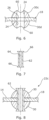
- FIGs 6 to 8 illustrate a further embodiment of a mounting bush 22c; which can be moulded in two stages.
- annular flange or body portions 30c, 30d are moulded on either side of the cushion material 14 about the aperture 26.
- the flange portions 30 each have a central aperture 24 that aligns with the aperture 26 in the cushion material.
- the flange portions 30 are part spherical, and are counter sunk 60 about the central aperture 24 on their outer surfaces.
- a central body portion 62 (illustrated separately in Figure 7 ) is moulded within the central apertures 24 of the flange portions 30 and the aperture 26 in cushion material 14.
- the central body portion 62 is in the form of an annular cylinder having a through bore 64.
- the central body portion 62 has radially outwardly directed flanges 66 at either end, which locate in the counter sunk recesses 60 of the flange portions 30 so as to lock the assembly together; with the cushion material firmly clamped between the flange portions in the completed bush as shown in Figure 8 .
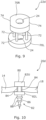
- FIG. 9 illustrates a further alternative embodiment of a mounting bush 22d, which can be moulded either before or after the aperture 26 is formed in the mounting region.
- the bush 22d does not have a central body portion; but has two substantially planar, annular body portions 70L, 70R which are moulded to either side of the cushion material on the mounting region 18. (The distance between body portions 70L and 70R is exaggerated in the Figure to allow the structure to be seen)
- Each body portion has an aperture 24 extending through it.
- the apertures 24 are aligned with one another on a common axis.
- a number of projections 72 extend between the body portions 70 through the cushion material.
- the projections are arranged on a diameter which is larger than that of the apertures 24 in the body portions.
- the projections serve to connect the body portions 70; and to resist rotation of the body portions 70 relative to the cushion material 14.
- the mounting bush 22d is moulded after an aperture 26 is formed in the cushion material, the bush is moulded so that the apertures 24 in the body portions align with the aperture 26 in the cushion material, which is substantially the same size as the apertures 24.
- the mounting bush can be moulded to the mounting region before an aperture 26 is formed through the cushion material.
- the aperture 26 in the cushion material can be produced at any suitable time prior to or whilst fitting the airbag to a vehicle with a fastener mounted through the bush.
- the aperture 26 through the cushion material 14 is formed by pressing a bolt or other fastener through the bush and the cushion material, whilst the airbag is being assembled.
- the bolt or fastener may be provided with a pointed and tapered end to make it easier to push through the material.
- the mounting bush 22d can be said to define a through bore comprising the aligned apertures 24 in the opposed body portions; and the aperture 26 in the cushion material.
- FIG 10 illustrates an alternative mounting member 20d in the form of a push-fit mounting fastener 80.
- the mounting member 20d according to this embodiment includes an integrally moulded clip 82 for insertion into an aperture in the vehicle body to secure the mounting region to the vehicle body.
- the mounting fastener 80 has a pair of body portions 82U, 82L moulded to either side of the cushion material 14 on the mounting region 18c ( Fig. 2 ).
- a number of projections 84 extend between the body portions 82U, 82L through the cushion material. The projections 84 interconnect the body portions 82U, 82L; and help to resist rotation of the body portions 82U, 82L relative to the cushion material.
- the moulded clip 82 projects outwardly from an outer end face of body portion 82L.
- the clip 82 in this embodiment is in the form of a so called "fir-tree" clip having a central spigot-like body 86 with a number of resiliently flexible circumferential ribs or flanges 88 spaced apart along its length.
- the clip is pressed into a hole in a body panel until the clip is firmly engaged in the hole; with at least one of the flanges engaged with the panel on its far side.
- the clip is tapered, having a conical body 86; and the outer diameter of the ribs 88 increases towards the body portion 82L. This enables the clip to be used with a range of different sized holes.
- the clip can have a substantially constant diameter along its length; although the free outer end will usually be tapered for ease of insertion.
- the use of a mounting member in the form of a push-fit mounting fastener 80 has the advantage of both reinforcing the cushion material 14 in the mounting region; and also of eliminating the need to use a bolt or other threaded fastener to secure the mounting region to the vehicle body, thus saving weight and eliminating the possibility of cross-threading.
- Most airbag cushions 12 will have a number of mounting regions 18; and a mounting member 20 will usually be moulded to each mounting region. However, this is not essential; and in some cases, it may be appropriate to only mould a mounting member 20 to one or to some of the mounting regions. All the mounting members 20 moulded to an airbag cushion 12 may be the same, or at least the same type. However, it will be appreciated that a mixture of different types of moulded mounting member 20 could be used on any given airbag, enabling the use of a mixture of push fit clips and threaded fasteners inserted through moulded bushes to attach the airbag.
- the mounting members 20 may be symmetrical on either side of the cushion material and/or rotationally. This is advantageous in certain circumstances, as it potentially allows a curtain airbag cushion 12 to be produced which is not restricted to use on one side of a vehicle or the other after the mounting members are moulded in place. In some cases, the curtain airbag cushion will not become a handed component until it is rolled prior to assembly.
- the outer profile of a mounting member 20 need not be symmetrical; and could be profiled on at least one side of the mounting region to fit in or against a feature of the vehicle body.
- FIG. 9 This is illustrated in Figure 9 , where at least one of the body portions 70 has flat sections 74 in an otherwise circular outer periphery to enable the mounting bush to be fitted against a ridge or other feature of the vehicle body.
- This concept is not limited to the use of flat sections in an otherwise circular peripheral profile; but can encompass any suitable profiling to enable a mounting member to be fitted in or against a feature on the vehicle body or other fixture. This concept can be applied to any of the mounting members described herein.
Landscapes
- Engineering & Computer Science (AREA)
- Mechanical Engineering (AREA)
- Air Bags (AREA)
Description
- The present invention relates to vehicle curtain airbags. Aspects of the invention relate to a vehicle airbag, to a vehicle, and to a method of manufacturing a vehicle airbag.
- Airbags are inflatable restraints commonly used in passenger vehicles to restrain occupants within an occupant compartment of the vehicle in the event of a collision, rollover incident, or the like. An airbag comprises an inflatable cushion made from a flexible material defining at least one internal chamber into which pressurised gas is introduced when the airbag is deployed. The inflated airbag provides an energy absorbing layer between an occupant and a rigid component of the vehicle, dissipating the forces experienced by the occupant. Curtain airbags are used to provide an energy absorbing layer between the side windows of a vehicle and its occupants in the event of a side impact or rollover incident. Typically, curtain airbags are mounted in pairs inside the vehicle adjacent to the roof, one on either side of an occupant compartment.
- In order to secure an airbag to the vehicle body or to some other fixed location, it is known to provide an aperture in a mounting region defined in a non-inflatable part of the airbag cushion. Curtain airbags may have a number of mounting tabs spaced along an upper edge of the airbag cushion, each tab having an aperture. Often a screw threaded fastener such as a bolt is inserted though the aperture to engage in a threaded aperture in the vehicle body, typically provided by a nut welded to the vehicle body. Alternatively, a mounting formation such as a hook may be affixed to the vehicle body and engaged through the aperture. The mounting regions are often reinforced, either by folding the material of the airbag cushion over and stitching to form a double thickness; or by sewing a reinforcing material to the airbag cushion material. In either case, this is a skilled operation with many potential failure modes in the manufacturing process.
- The use of bolts and weld nuts to secure an airbag is also disadvantageous as they are heavy, adding to the overall weight of the vehicle; and are susceptible to cross threading. This is a particular problem for curtain airbags, where it can be difficult for an operative to hold the airbag in position whilst attempting to correctly insert a bolt into a weld nut in an overhead position.
US2015/158450 A1 discloses a curtain airbag according to the preamble of claim 1. -
US2005/098996A1 discloses a unitaryplastic sleeve 52 which facilitates attachment of aninflatable chamber 50 for a knee bolster pad 12b to a receivingbracket 54 by a total of 16 bolts. - Aspects of the invention relate to a vehicle curtain airbag; to a vehicle; and to a method of manufacturing a vehicle airbag.
- According to a first aspect of the invention, there is provided a vehicle curtain airbag comprising an inflatable cushion made from flexible material defining at least one internal chamber, the material also defining a mounting region for attachment of the airbag cushion to a fixing point in a vehicle, characterized in that: a plurality of polymeric mounting members are moulded to the material of the airbag cushion within at least two of the mounting regions; wherein at least one polymeric mounting member is profiled to fit against or within a feature of a vehicle cant rail to which it is to be assembled in use.
- Moulding a polymeric mounting member to the airbag cushion material reinforces the material in the mounting region without the need for stitching.
- At least one mounting member may comprise a mounting bush. The mounting bush may define a through bore. The mounting bush may be adapted to enable a threaded fastener such as a bolt to be inserted through the bore for engagement with a threaded aperture in the vehicle fixing point. An aperture may be defined in the mounting region in alignment with the through bore. In this case, the mounting bush may comprise a body portion which extends through the aperture; and flange portions which project radially outwardly at either end of the body portion, and which are moulded to opposed sides of the material. The bore may extend through the body portion. Alternatively, the mounting bush may comprise opposed body portions moulded on opposite sides of the cushion material, the opposed body portions each defining an aperture, which apertures are aligned to define a through bore. There may be a corresponding aperture through the cushion material in alignment with the apertures in the opposed body portions.
- At least one mounting bush may be moulded as a single integral component. The mounting bush may be manufactured in a multi-stage moulding process.
- At least one mounting member may comprise a push-fit mounting fastener. In this case, the mounting member may comprise an integrally moulded push-fit clip for insertion into an aperture in a vehicle fixing point. The push-fit clip may be a resilient push-fit clip. The push-fit clip may be a fir-tree clip.
- At least one mounting member may have opposed portions moulded to either side of the cushion material in said mounting region. The mounting member may have a plurality of spaced projections which extend through the material between the opposed portions.
- The airbag cushion may have a plurality of mounting regions with a polymeric mounting member being moulded to at least one of the mounting regions. Where the airbag cushion has two or more mounting regions, a respective polymeric mounting member may be moulded to each of two or more of the mounting regions. All the mounting members may be the same. Alternatively, at least one mounting member may be different from at least one other mounting member. At least one mounting member may be a mounting bush type mounting member as set out above; and at least one other mounting member may be a push-fit mounting fastener type mounting member as set out above.
- The airbag cushion material may be a fabric. Material defining the mounting member may penetrate between fibres of the fabric.
- In accordance with a second aspect of the invention, there is provided a vehicle comprising a vehicle curtain airbag according to the first aspect of the invention as set out above. Where a mounting member is a mounting bush, the airbag may be secured to a fixing point of the vehicle by means of a threaded fastener inserted through the bush and engaging in a threaded hole in the fixing point. Where the mounting member is a push-fit mounting fastener as set out above, the airbag may be secured to the fixing point by means of the push-fit clip engaging in a hole in the vehicle fixing point. The mounting member is profiled to fit against or within a feature of the vehicle. Such profiles may include hooks which hang the mounting member off a vehicle structural member, such as a cant rail, while airbag mounting bolts are fitted.
- In accordance with a third aspect of the invention, there is provided a method of manufacturing a vehicle curtain airbag comprising an inflatable cushion made from flexible material defining at least one internal chamber, the method being characterized in comprising moulding a plurality of polymeric mounting members to the airbag cushion within non-inflatable mounting regions of the cushion;
wherein at least one polymeric mounting member is profiled to fit within or against a feature of a vehicle cant rail to which it is to be assembled in use. - The method may comprise manufacturing a vehicle airbag according to the first aspect of the invention as set out above.
- The method may comprise moulding a mounting member in the form of a mounting bush defining a central bore. The mounting bush may be adapted to enable a threaded fastener, such as a bolt, to be inserted through the bore for engagement with a threaded aperture in the vehicle fixing point. The method may comprise forming an aperture through the cushion material in the mounting region in alignment with the through bore. The method may comprise moulding a mounting bush with a body portion extending through the aperture; and flange portions which project radially outwardly at either end of the body portion, which flange portions are moulded to opposed sides of the cushion material. The method may comprise moulding the mounting bush with a bore extending through the body portion. The method may comprise moulding the mounting bush as a single integral component in a single stage moulding operation. The method may comprise moulding the mounting bush in a multi-stage moulding process.
- The method may comprise moulding opposed body portions on either side of the cushion material in a first stage, each body portion having an aperture, and subsequently moulding an annular body portion extending through an aperture in the cushion material and the apertures in the opposed body portions in a second stage. The method may comprise producing a first stage moulding comprising a body portion extending through an aperture in the cushion material, and a first flange at a first end of the body portion which is moulded to the cushion material on one side; and subsequently over moulding a second stage moulding about a second end of the body portion, the second stage moulding forming a second flange moulded to the cushion material on a second side of the cushion material opposite to the first.
- The method may comprise moulding a mounting member in the form of a push-fit mounting fastener having an integrally moulded push-fit clip for insertion into an aperture in a vehicle fixing point. The push-fit clip may be a resilient push-fit clip. The push-fit clip may be a fir-tree clip.
- The method may comprise moulding the mounting member with a plurality of spaced formations which extend through the cushion material.
- The method may comprise manufacturing an airbag in which the airbag cushion has a plurality of mounting regions, the method comprising moulding a polymeric mounting member to at least two of the mounting regions. The method may comprise moulding a respective polymeric mounting member moulded to each of two or more mounting regions of an airbag cushion. In an embodiment, all the respective mounting members are the same type. Alternatively, at least one respective mounting member may be different from at least one other respective mounting member. The method may comprise moulding at least one respective mounting member which is a mounting bush type mounting member and moulding at least one other respective mounting member which is a push-fit mounting fastener type mounting member.
- The method may comprise moulding opposed portions of a mounting member to either side of the cushion material in said mounting region. The method may comprise moulding a plurality of spaced projections extending through the material between the opposed portions. In an embodiment, the method comprises moulding each of the opposed portions with an aperture, the apertures being aligned on a common axis. The method may comprise forming a corresponding aperture in the cushion material which aligns with the apertures in the opposed portions for each mounting member. The method may comprise forming the aperture in the cushion material either before or after moulding the opposed portions. The method may comprise forming the or each aperture in the cushion material when mounting the airbag to a vehicle.
- The airbag cushion material may be a fabric; and the method may comprise moulding the mounting member such that material defining the mounting member penetrates between fibres of the fabric.
- The method also comprises customising at least one mounting member to fit a location on a vehicle to which the airbag is to be fitted, by profiling the mounting member so as to fit against or within a feature of a vehicle to which it is to be assembled.
- The method may comprise forming an aperture in the cushion material by punching or laser cutting.
- In order that the invention may be more clearly understood, embodiments thereof will now be described - by way of example only - with reference to the accompanying drawings, of which:
- Figure 1
- is a somewhat schematic elevational view of a curtain airbag in accordance with an aspect of the invention in an unrolled configuration, illustrating the location of mounting regions along an upper edge;
- Figure 2
- shows the curtain airbag of
Figure 1 in a rolled configuration for attachment to a vehicle; - Figure 3
- is a cross sectional view taken on line X-X in
Figure 2 through a first of the mounting regions of the curtain airbag ofFigures 1 and 2 , illustrating a first embodiment of a mounting member in the form of a mounting bush moulded to the cushion; - Figure 4
- is a cross sectional view through a moulding apparatus illustrating a method of moulding the mounting bush shown in
Figure 3 to a mounting region of an airbag in accordance with an aspect of the invention; - Figure 5
- is a cross sectional view through a mounting region of an airbag in accordance with the invention, illustrating an alternative embodiment of a mounting bush similar to that of
Figure 3 but which is moulded to the airbag in a two stage process; - Figures 6 to 8
- are a series of cross sectional views illustrating a further alternative embodiment of a mounting bush similar to that in
Figure 3 , but which is moulded to the airbag in a two stage process; - Figure 9
- is a perspective view of a still further embodiment of a mounting bush similar to that in
Figure 3 , but which can be moulded to the mounting region before forming an aperture through the mounting region; and - Figure 10
- is a cross sectional view taken on line Y-Y in
figure 2 through a second of the mounting regions of the curtain airbag ofFigures 1 and 2 , illustrating an alternative embodiment of a mounting member in the form of a push-fit mounting fastener having an integrally moulded resilient clip. - A
curtain airbag 10 is illustrated inFigure 1 in an un-rolled but uninflated configuration prior to assembly into a vehicle. Thecurtain airbag 10 comprises aninflatable cushion 12 made fromflexible material 14 which defines at least one internal cavity (16,fig. 4 ). The flexible material can be any suitable material for airbags, as is known in the art. The flexible material may, for example, be a woven fabric; and could be made of nylon and/or polyester. Theinflatable cushion 12 may be constructed from two or more layers of flexible material assembled together. Alternatively, the inflatable cushion can be formed by a single layer of material which is woven to define the at least oneinflatable cavity 16. - A number of mounting
regions 18, identified individually as 18a, 18b, 18c, are spaced apart along an edge of the airbag cushion which is uppermost when the airbag is assembled in a vehicle. The mountingregions internal cavity 16. Each mountingregion curtain airbag 10, the fixing point will typically be on a structural element of the vehicle body, such as a cant rail (not shown). In the embodiment shown, each mountingregion -
Figure 2 shows thecurtain airbag cushion 12 in a rolled up configuration in which it is assembled to the vehicle. Thecurtain airbag cushion 12 may be encased in at least one airbag wrap (not shown) to protect it; and to hold it in its rolled up configuration, prior to deployment. Once thecurtain airbag 10 is correctly assembled to the vehicle, the headlining and any required pillar trims can be fitted to the vehicle. These will cover thecurtain airbags 10 when fitted, obscuring them from view. Theairbag cushion 12 is operatively connected to a source of pressurised gas (not shown) forming part of a deployment system for the airbag. - In accordance with an aspect of the invention, mounting
members regions airbag cushion 12. Typically, the mounting members 20 are made from polymeric materials, including thermoplastic polymeric materials such as polypropylene (PP) or nylon; either of which could be filled with glass fibres for strength. The mounting members 20 can take different forms. - In one embodiment as illustrated in
Figure 3 , a mountingmember 20a on a first of the mountingregions 18a is in the form of a mountingbush 22a defining acentral bore 24 which is moulded through anaperture 26 in thecushion material 14. The mountingbush 22a is used to mount the airbag by inserting a threaded fastener such as a bolt through the bush for engagement with a threaded hole on the vehicle's body or other fixing point. Alternatively, a hook or other like attachment member attached to the vehicle body could be inserted through the bush. The mountingbush 22a reinforces theairbag cushion material 14 in the mounting region; avoiding the need to use stitching to either attach a reinforcing material, or to hold a folded over portion of the material in place. Inserting a fastening bolt through a mounting bush has also been found to be simpler than trying to insert a bolt through an aperture in the cushion material without a mounting bush. It may be preferred to insert the bolt through the bush prior to assembly to the vehicle, by using a retaining member such as a locking washer which grips the thread on the bolt. - The mounting
bush 22a in this embodiment has a central,cylindrical body portion 28 which extends through theaperture 26 in thecushion material 14 withcircular flanges radial flanges 30 extend over thecushion material 14 surrounding the aperture on respective sides of the mounting region. Thecentral bore 24 extends fully through the twoflanges 30 and thecylindrical body portion 28. - The mounting
bush 22a is a single integral component which is moulded in one piece to the mountingregion 18a after theaperture 26 has been formed. A method of moulding the mountingbush 22a is illustrated schematically inFigure 4 . Amould tool 32 has afirst part 34 and asecond part 36 which locate either side of a mountingregion 18 of anairbag cushion 12 having anaperture 26. Theaperture 26 may be formed by any suitable means, including punching or laser cutting or the like. The mountingregion 18 is a non-inflatable part of thecushion material 14 lying outside aninternal cavity 16. The cushion is not inflated at this stage; the spacing between sections of thecushion material 14 which defines thecavity 16 is exaggerated inFigure 4 for clarity. - The first and
second parts region 18 between their end faces 38U, 38L. Each part of the mould tool has anannular cavity central spigot aperture 26. The annular cavities 40 have a larger outer diameter than theaperture 26. Thespigot 42a on the first part of the mould tool projects beyond theend face 38U of the tool, so as to locate within theaperture 26 in the cushion material; and to abut thespigot 42b on the second part of thetool 36 when the tool parts are brought together. Asmall diameter pin 44 on the end of thespigot 42a on the first tool part engages in a corresponding blind bore 46 formed in the end of thespigot 42b on the second part to align the spigots and to hold them in place. The spigots 42 have a diameter smaller than that of theaperture 26, and define thecentral bore 24 of the mounting bush. In use, the twoparts region 18 of thecushion material 14 between them; and molten material for forming the mountingbush 22a is introduced into the cavities 40. The molten material fills the cavities 40 and passes through theaperture 26 in the cushion material about the spigots 42. Once the material has solidified sufficiently, the two parts of thetool -
Figure 5 illustrates an alternative embodiment of a mountingbush 22b, which is similar to thebush 22a inFigure 3 ; but which is moulded in two stages. A first stage moulding 50 forms thecentral body portion 28 and afirst flange 30a of the mounting bush at a first end of the central body portion. The first stage moulding 50 carries anassembly flange 52 which projects radially outwardly at the second end of thecentral body portion 28, spaced from thecushion material 14 on the opposite side of the mounting region to thefirst flange 30a. Theassembly flange 52 is smaller than thefirst flange portion 30a. Once thefirst stage moulding 50 has solidified sufficiently, a second stage moulding 54 is moulded about the second end of the first moulding where it projects beyond thecushion material 14. The second stage moulding surrounds theassembly flange 52 to form asecond flange 30b of the mounting bush which overlies the cushion material surrounding theaperture 26. Once both of the first andsecond stage mouldings cushion material 14 is firmly clamped between the first andsecond stage mouldings -
Figures 6 to 8 illustrate a further embodiment of a mountingbush 22c; which can be moulded in two stages. In a first stage as illustrated inFigure 6 , annular flange orbody portions cushion material 14 about theaperture 26. Theflange portions 30 each have acentral aperture 24 that aligns with theaperture 26 in the cushion material. Theflange portions 30 are part spherical, and are counter sunk 60 about thecentral aperture 24 on their outer surfaces. - In a second stage, a central body portion 62 (illustrated separately in
Figure 7 ) is moulded within thecentral apertures 24 of theflange portions 30 and theaperture 26 incushion material 14. Thecentral body portion 62 is in the form of an annular cylinder having a throughbore 64. Thecentral body portion 62 has radially outwardly directedflanges 66 at either end, which locate in the counter sunk recesses 60 of theflange portions 30 so as to lock the assembly together; with the cushion material firmly clamped between the flange portions in the completed bush as shown inFigure 8 . - The mounting
bushes cushion material 14 in the mountingregion 18 after theaperture 26 is formed in the cushion material.Figure 9 illustrates a further alternative embodiment of a mountingbush 22d, which can be moulded either before or after theaperture 26 is formed in the mounting region. Thebush 22d does not have a central body portion; but has two substantially planar,annular body portions region 18. (The distance betweenbody portions aperture 24 extending through it. Theapertures 24 are aligned with one another on a common axis. A number of projections 72 (four in this case) extend between the body portions 70 through the cushion material. The projections are arranged on a diameter which is larger than that of theapertures 24 in the body portions. The projections serve to connect the body portions 70; and to resist rotation of the body portions 70 relative to thecushion material 14. Where the mountingbush 22d is moulded after anaperture 26 is formed in the cushion material, the bush is moulded so that theapertures 24 in the body portions align with theaperture 26 in the cushion material, which is substantially the same size as theapertures 24. However, the mounting bush can be moulded to the mounting region before anaperture 26 is formed through the cushion material. In this case, theaperture 26 in the cushion material can be produced at any suitable time prior to or whilst fitting the airbag to a vehicle with a fastener mounted through the bush. In one embodiment, theaperture 26 through thecushion material 14 is formed by pressing a bolt or other fastener through the bush and the cushion material, whilst the airbag is being assembled. The bolt or fastener may be provided with a pointed and tapered end to make it easier to push through the material. At least once theaperture 26 is formed, the mountingbush 22d can be said to define a through bore comprising the alignedapertures 24 in the opposed body portions; and theaperture 26 in the cushion material. -
Figure 10 illustrates analternative mounting member 20d in the form of a push-fit mounting fastener 80. The mountingmember 20d according to this embodiment includes an integrally mouldedclip 82 for insertion into an aperture in the vehicle body to secure the mounting region to the vehicle body. The mountingfastener 80 has a pair ofbody portions cushion material 14 on the mountingregion 18c (Fig. 2 ). A number ofprojections 84 extend between thebody portions projections 84 interconnect thebody portions body portions clip 82 projects outwardly from an outer end face ofbody portion 82L. Theclip 82 in this embodiment is in the form of a so called "fir-tree" clip having a central spigot-like body 86 with a number of resiliently flexible circumferential ribs orflanges 88 spaced apart along its length. In use, the clip is pressed into a hole in a body panel until the clip is firmly engaged in the hole; with at least one of the flanges engaged with the panel on its far side. In the embodiment illustrated, the clip is tapered, having aconical body 86; and the outer diameter of theribs 88 increases towards thebody portion 82L. This enables the clip to be used with a range of different sized holes. However, this is not essential, and the clip can have a substantially constant diameter along its length; although the free outer end will usually be tapered for ease of insertion. The use of a mounting member in the form of a push-fit mounting fastener 80 has the advantage of both reinforcing thecushion material 14 in the mounting region; and also of eliminating the need to use a bolt or other threaded fastener to secure the mounting region to the vehicle body, thus saving weight and eliminating the possibility of cross-threading. - Most airbag cushions 12 will have a number of mounting
regions 18; and a mounting member 20 will usually be moulded to each mounting region. However, this is not essential; and in some cases, it may be appropriate to only mould a mounting member 20 to one or to some of the mounting regions. All the mounting members 20 moulded to anairbag cushion 12 may be the same, or at least the same type. However, it will be appreciated that a mixture of different types of moulded mounting member 20 could be used on any given airbag, enabling the use of a mixture of push fit clips and threaded fasteners inserted through moulded bushes to attach the airbag. - The mounting members 20; especially mounting
bushes curtain airbag cushion 12 to be produced which is not restricted to use on one side of a vehicle or the other after the mounting members are moulded in place. In some cases, the curtain airbag cushion will not become a handed component until it is rolled prior to assembly. However, the outer profile of a mounting member 20 need not be symmetrical; and could be profiled on at least one side of the mounting region to fit in or against a feature of the vehicle body. This is illustrated inFigure 9 , where at least one of the body portions 70 hasflat sections 74 in an otherwise circular outer periphery to enable the mounting bush to be fitted against a ridge or other feature of the vehicle body. This concept is not limited to the use of flat sections in an otherwise circular peripheral profile; but can encompass any suitable profiling to enable a mounting member to be fitted in or against a feature on the vehicle body or other fixture. This concept can be applied to any of the mounting members described herein. - The above embodiments are described by way of example only. Many variations are possible without departing from the scope of the invention as defined in the appended claims.
Claims (13)
- A vehicle curtain airbag (10) comprising an inflatable cushion (12) made from flexible material (14) defining at least one internal chamber (16), the material also defining a plurality of mounting regions (18a, 18b, 18c) for attachment of the airbag cushion to a fixing point in a vehicle, wherein a plurality of polymeric mounting members (20a, 20b, 20c, 20d, 22c, 22d) are moulded to the airbag cushion (12) within at least two of the mounting regions (18a, 18b, 18c);
characterized in that:
at least one polymeric mounting member (20a, 20b, 20c, 20d, 22c, 22d) is profiled to fit within or against a feature of a vehicle cant rail to which it is to be assembled in use. - A vehicle airbag (10) as claimed in claim 1, wherein the mounting members comprise mounting bushes (22a, 22b, 22c, 22d) defining through bores (24, 64).
- A vehicle airbag (10) as claimed in claim 2, wherein an aperture (26) is defined in the mounting region (18a, 18b, 18c) in alignment with each through bore (24, 64).
- A vehicle airbag (10) as claimed in claim 1, wherein at least one moulded mounting member (20d) comprises a push-fit mounting fastener (80).
- A vehicle curtain airbag (10) as claimed in claim 4, wherein at least one mounting member (20d) comprises an integrally moulded push-fit clip (82) for insertion into an aperture in a vehicle fixing point.
- A vehicle curtain airbag (10) as claimed in claim 1, wherein at least one of the mounting members (20a, 20b, 20c) is a mounting bush (22a, 22b, 22c, 22d) according to claim 2, and at least one of the mounting members (20d) is a push-fit mounting fastener (80) according to claim 4 or claim 5.
- A vehicle curtain airbag (10) as claimed in any one of the preceding claims, wherein at least one mounting member (20a, 20b, 20c, 20d, 22c, 22d) has opposed portions (30R, 30L, 30a, 30b, 30c, 30d, 82U, 82L, 70R, 70L) located on either side of the cushion material (14) in said mounting region (18a, 18b, 18c).
- A vehicle curtain airbag (10) as claimed in claim 7, wherein the mounting member (20d, 22d) has a plurality of spaced projections (84, 72) which extend through the material (14) between the opposed portions (82U, 82L; 70R, 70L).
- A vehicle curtain airbag (10) as claimed in claim 8, wherein the airbag cushion material (14) is a fabric, and material defining the mounting member (20d, 22d) penetrates between fibres of the fabric.
- A vehicle comprising a vehicle curtain airbag (10) according to any one of the preceding claims.
- A method of manufacturing a vehicle curtain airbag (10) comprising an inflatable cushion (12) made from flexible material (14) defining at least one internal chamber (16), the method being characterized in comprising moulding a plurality of polymeric mounting members (20a, 20b, 20c, 20d, 22c, 22d) to the airbag cushion (12) within non-inflatable mounting regions (18) of the cushion (12);
wherein
at least one polymeric mounting member (20a, 20b, 20c, 20d, 22c, 22d) is profiled to fit within or against a feature of a vehicle cant rail to which it is to be assembled in use. - A method as claimed in claim 11 the method comprising moulding the mounting member (20a, 20d, 22d) in a single stage moulding process.
- A method as claimed in claim 11, the method comprising moulding the mounting member (22b, 22c) in a multiple stage moulding process.
Applications Claiming Priority (1)
| Application Number | Priority Date | Filing Date | Title |
|---|---|---|---|
| GB1918192.4A GB2589891A (en) | 2019-12-11 | 2019-12-11 | Improvements in and relating to airbags |
Publications (2)
| Publication Number | Publication Date |
|---|---|
| EP3835138A1 EP3835138A1 (en) | 2021-06-16 |
| EP3835138B1 true EP3835138B1 (en) | 2023-02-08 |
Family
ID=69172110
Family Applications (1)
| Application Number | Title | Priority Date | Filing Date |
|---|---|---|---|
| EP20212829.4A Active EP3835138B1 (en) | 2019-12-11 | 2020-12-09 | Improvements relating to airbags |
Country Status (2)
| Country | Link |
|---|---|
| EP (1) | EP3835138B1 (en) |
| GB (1) | GB2589891A (en) |
Family Cites Families (7)
| Publication number | Priority date | Publication date | Assignee | Title |
|---|---|---|---|---|
| US6851702B2 (en) * | 2001-08-29 | 2005-02-08 | Autoliv Asp, Inc. | Mounting assembly for inflatable curtain |
| DE10300757A1 (en) * | 2003-01-11 | 2005-06-02 | Adam Opel Ag | Airbag module for a motor vehicle with an airbag module housing and method for producing a welded connection between an inflation opening of an airbag and a gas outlet opening of an airbag module housing |
| US20050098996A1 (en) * | 2003-11-06 | 2005-05-12 | Enders Mark L. | Knee bolster cover |
| DE102008033694A1 (en) * | 2008-07-17 | 2010-01-21 | Trw Automotive Gmbh | Airbag module with a gas bag, in particular a head-side gas bag |
| JP5546429B2 (en) * | 2010-11-25 | 2014-07-09 | 芦森工業株式会社 | Airbag device |
| DE202011108508U1 (en) * | 2011-11-30 | 2012-03-02 | Key Safety Systems, Inc. | Airbag for a vehicle, in particular motor vehicle |
| JP6107629B2 (en) * | 2013-12-06 | 2017-04-05 | 豊田合成株式会社 | Head protection airbag device |
-
2019
- 2019-12-11 GB GB1918192.4A patent/GB2589891A/en not_active Withdrawn
-
2020
- 2020-12-09 EP EP20212829.4A patent/EP3835138B1/en active Active
Also Published As
| Publication number | Publication date |
|---|---|
| GB2589891A (en) | 2021-06-16 |
| GB201918192D0 (en) | 2020-01-22 |
| EP3835138A1 (en) | 2021-06-16 |
Similar Documents
| Publication | Publication Date | Title |
|---|---|---|
| US5193846A (en) | Air bag clamping device | |
| US5253892A (en) | Air bag | |
| US6161865A (en) | Interlocking airbag attachment and module assembly | |
| KR100503667B1 (en) | Roof panel lining of a vehicle with preassembled head protection elements(head bags) | |
| JP2604972B2 (en) | Apparatus and method for attaching inflatable cushion to reaction vessel member | |
| EP0754603B1 (en) | Air bag inflator module for snap-on attachment to a steering wheel | |
| US20100072735A1 (en) | Fastener clip and method of fabricating the same | |
| US5692770A (en) | Modular steering wheel and airbag combination | |
| JP3015716U (en) | Airbag inflator module assembly | |
| US20040150196A1 (en) | Quick connect cushion mounting system | |
| US5443284A (en) | Air bag cushion rivetless retainer ring, axial pin method | |
| JP2006088985A (en) | Head protection airbag device | |
| JP3021505U (en) | Inflatable cushion assembly incorporated into an inflatable detention system | |
| US20070241543A1 (en) | Guide plate for side air bag | |
| WO2013032561A1 (en) | Airbag tethering clip assembly | |
| JPH04201756A (en) | Air bag mounting structure for air bag device | |
| DE20114507U1 (en) | Airbag module | |
| JPH05131887A (en) | Air bag inflating device and installation method thereof | |
| BRPI0411682B1 (en) | Automotive child safety seat restraint, locking wire and method of manufacturing an automotive child safety seat restraint | |
| US5845928A (en) | Attachment device for an inflatable protective cushion | |
| EP0825073B1 (en) | Cover mounting arrangement for airbag module | |
| EP3835138B1 (en) | Improvements relating to airbags | |
| EP2197711A1 (en) | High strength airbag attachment for use with flanged inflators | |
| US7213839B2 (en) | Air-bag | |
| WO2008099243A1 (en) | Fastener for air-bag curtain |
Legal Events
| Date | Code | Title | Description |
|---|---|---|---|
| PUAI | Public reference made under article 153(3) epc to a published international application that has entered the european phase |
Free format text: ORIGINAL CODE: 0009012 |
|
| STAA | Information on the status of an ep patent application or granted ep patent |
Free format text: STATUS: THE APPLICATION HAS BEEN PUBLISHED |
|
| AK | Designated contracting states |
Kind code of ref document: A1 Designated state(s): AL AT BE BG CH CY CZ DE DK EE ES FI FR GB GR HR HU IE IS IT LI LT LU LV MC MK MT NL NO PL PT RO RS SE SI SK SM TR |
|
| STAA | Information on the status of an ep patent application or granted ep patent |
Free format text: STATUS: REQUEST FOR EXAMINATION WAS MADE |
|
| 17P | Request for examination filed |
Effective date: 20211216 |
|
| RBV | Designated contracting states (corrected) |
Designated state(s): AL AT BE BG CH CY CZ DE DK EE ES FI FR GB GR HR HU IE IS IT LI LT LU LV MC MK MT NL NO PL PT RO RS SE SI SK SM TR |
|
| GRAP | Despatch of communication of intention to grant a patent |
Free format text: ORIGINAL CODE: EPIDOSNIGR1 |
|
| STAA | Information on the status of an ep patent application or granted ep patent |
Free format text: STATUS: GRANT OF PATENT IS INTENDED |
|
| INTG | Intention to grant announced |
Effective date: 20220407 |
|
| RAP3 | Party data changed (applicant data changed or rights of an application transferred) |
Owner name: NISSAN MOTOR MANUFACTURING (UK) LIMITED |
|
| GRAJ | Information related to disapproval of communication of intention to grant by the applicant or resumption of examination proceedings by the epo deleted |
Free format text: ORIGINAL CODE: EPIDOSDIGR1 |
|
| STAA | Information on the status of an ep patent application or granted ep patent |
Free format text: STATUS: REQUEST FOR EXAMINATION WAS MADE |
|
| INTC | Intention to grant announced (deleted) | ||
| GRAP | Despatch of communication of intention to grant a patent |
Free format text: ORIGINAL CODE: EPIDOSNIGR1 |
|
| STAA | Information on the status of an ep patent application or granted ep patent |
Free format text: STATUS: GRANT OF PATENT IS INTENDED |
|
| INTG | Intention to grant announced |
Effective date: 20220714 |
|
| GRAS | Grant fee paid |
Free format text: ORIGINAL CODE: EPIDOSNIGR3 |
|
| GRAA | (expected) grant |
Free format text: ORIGINAL CODE: 0009210 |
|
| STAA | Information on the status of an ep patent application or granted ep patent |
Free format text: STATUS: THE PATENT HAS BEEN GRANTED |
|
| AK | Designated contracting states |
Kind code of ref document: B1 Designated state(s): AL AT BE BG CH CY CZ DE DK EE ES FI FR GB GR HR HU IE IS IT LI LT LU LV MC MK MT NL NO PL PT RO RS SE SI SK SM TR |
|
| REG | Reference to a national code |
Ref country code: GB Ref legal event code: FG4D |
|
| REG | Reference to a national code |
Ref country code: CH Ref legal event code: EP Ref country code: AT Ref legal event code: REF Ref document number: 1547396 Country of ref document: AT Kind code of ref document: T Effective date: 20230215 |
|
| REG | Reference to a national code |
Ref country code: DE Ref legal event code: R096 Ref document number: 602020007982 Country of ref document: DE |
|
| REG | Reference to a national code |
Ref country code: IE Ref legal event code: FG4D |
|
| REG | Reference to a national code |
Ref country code: LT Ref legal event code: MG9D |
|
| REG | Reference to a national code |
Ref country code: NL Ref legal event code: MP Effective date: 20230208 |
|
| REG | Reference to a national code |
Ref country code: AT Ref legal event code: MK05 Ref document number: 1547396 Country of ref document: AT Kind code of ref document: T Effective date: 20230208 |
|
| PG25 | Lapsed in a contracting state [announced via postgrant information from national office to epo] |
Ref country code: RS Free format text: LAPSE BECAUSE OF FAILURE TO SUBMIT A TRANSLATION OF THE DESCRIPTION OR TO PAY THE FEE WITHIN THE PRESCRIBED TIME-LIMIT Effective date: 20230208 Ref country code: PT Free format text: LAPSE BECAUSE OF FAILURE TO SUBMIT A TRANSLATION OF THE DESCRIPTION OR TO PAY THE FEE WITHIN THE PRESCRIBED TIME-LIMIT Effective date: 20230609 Ref country code: NO Free format text: LAPSE BECAUSE OF FAILURE TO SUBMIT A TRANSLATION OF THE DESCRIPTION OR TO PAY THE FEE WITHIN THE PRESCRIBED TIME-LIMIT Effective date: 20230508 Ref country code: NL Free format text: LAPSE BECAUSE OF FAILURE TO SUBMIT A TRANSLATION OF THE DESCRIPTION OR TO PAY THE FEE WITHIN THE PRESCRIBED TIME-LIMIT Effective date: 20230208 Ref country code: LV Free format text: LAPSE BECAUSE OF FAILURE TO SUBMIT A TRANSLATION OF THE DESCRIPTION OR TO PAY THE FEE WITHIN THE PRESCRIBED TIME-LIMIT Effective date: 20230208 Ref country code: LT Free format text: LAPSE BECAUSE OF FAILURE TO SUBMIT A TRANSLATION OF THE DESCRIPTION OR TO PAY THE FEE WITHIN THE PRESCRIBED TIME-LIMIT Effective date: 20230208 Ref country code: HR Free format text: LAPSE BECAUSE OF FAILURE TO SUBMIT A TRANSLATION OF THE DESCRIPTION OR TO PAY THE FEE WITHIN THE PRESCRIBED TIME-LIMIT Effective date: 20230208 Ref country code: ES Free format text: LAPSE BECAUSE OF FAILURE TO SUBMIT A TRANSLATION OF THE DESCRIPTION OR TO PAY THE FEE WITHIN THE PRESCRIBED TIME-LIMIT Effective date: 20230208 Ref country code: AT Free format text: LAPSE BECAUSE OF FAILURE TO SUBMIT A TRANSLATION OF THE DESCRIPTION OR TO PAY THE FEE WITHIN THE PRESCRIBED TIME-LIMIT Effective date: 20230208 |
|
| PG25 | Lapsed in a contracting state [announced via postgrant information from national office to epo] |
Ref country code: SE Free format text: LAPSE BECAUSE OF FAILURE TO SUBMIT A TRANSLATION OF THE DESCRIPTION OR TO PAY THE FEE WITHIN THE PRESCRIBED TIME-LIMIT Effective date: 20230208 Ref country code: PL Free format text: LAPSE BECAUSE OF FAILURE TO SUBMIT A TRANSLATION OF THE DESCRIPTION OR TO PAY THE FEE WITHIN THE PRESCRIBED TIME-LIMIT Effective date: 20230208 Ref country code: IS Free format text: LAPSE BECAUSE OF FAILURE TO SUBMIT A TRANSLATION OF THE DESCRIPTION OR TO PAY THE FEE WITHIN THE PRESCRIBED TIME-LIMIT Effective date: 20230608 Ref country code: GR Free format text: LAPSE BECAUSE OF FAILURE TO SUBMIT A TRANSLATION OF THE DESCRIPTION OR TO PAY THE FEE WITHIN THE PRESCRIBED TIME-LIMIT Effective date: 20230509 Ref country code: FI Free format text: LAPSE BECAUSE OF FAILURE TO SUBMIT A TRANSLATION OF THE DESCRIPTION OR TO PAY THE FEE WITHIN THE PRESCRIBED TIME-LIMIT Effective date: 20230208 |
|
| PG25 | Lapsed in a contracting state [announced via postgrant information from national office to epo] |
Ref country code: SM Free format text: LAPSE BECAUSE OF FAILURE TO SUBMIT A TRANSLATION OF THE DESCRIPTION OR TO PAY THE FEE WITHIN THE PRESCRIBED TIME-LIMIT Effective date: 20230208 Ref country code: RO Free format text: LAPSE BECAUSE OF FAILURE TO SUBMIT A TRANSLATION OF THE DESCRIPTION OR TO PAY THE FEE WITHIN THE PRESCRIBED TIME-LIMIT Effective date: 20230208 Ref country code: EE Free format text: LAPSE BECAUSE OF FAILURE TO SUBMIT A TRANSLATION OF THE DESCRIPTION OR TO PAY THE FEE WITHIN THE PRESCRIBED TIME-LIMIT Effective date: 20230208 Ref country code: DK Free format text: LAPSE BECAUSE OF FAILURE TO SUBMIT A TRANSLATION OF THE DESCRIPTION OR TO PAY THE FEE WITHIN THE PRESCRIBED TIME-LIMIT Effective date: 20230208 Ref country code: CZ Free format text: LAPSE BECAUSE OF FAILURE TO SUBMIT A TRANSLATION OF THE DESCRIPTION OR TO PAY THE FEE WITHIN THE PRESCRIBED TIME-LIMIT Effective date: 20230208 |
|
| REG | Reference to a national code |
Ref country code: DE Ref legal event code: R097 Ref document number: 602020007982 Country of ref document: DE |
|
| PG25 | Lapsed in a contracting state [announced via postgrant information from national office to epo] |
Ref country code: SK Free format text: LAPSE BECAUSE OF FAILURE TO SUBMIT A TRANSLATION OF THE DESCRIPTION OR TO PAY THE FEE WITHIN THE PRESCRIBED TIME-LIMIT Effective date: 20230208 |
|
| PLBE | No opposition filed within time limit |
Free format text: ORIGINAL CODE: 0009261 |
|
| STAA | Information on the status of an ep patent application or granted ep patent |
Free format text: STATUS: NO OPPOSITION FILED WITHIN TIME LIMIT |
|
| 26N | No opposition filed |
Effective date: 20231109 |
|
| PG25 | Lapsed in a contracting state [announced via postgrant information from national office to epo] |
Ref country code: SI Free format text: LAPSE BECAUSE OF FAILURE TO SUBMIT A TRANSLATION OF THE DESCRIPTION OR TO PAY THE FEE WITHIN THE PRESCRIBED TIME-LIMIT Effective date: 20230208 |
|
| PG25 | Lapsed in a contracting state [announced via postgrant information from national office to epo] |
Ref country code: IT Free format text: LAPSE BECAUSE OF FAILURE TO SUBMIT A TRANSLATION OF THE DESCRIPTION OR TO PAY THE FEE WITHIN THE PRESCRIBED TIME-LIMIT Effective date: 20230208 |
|
| REG | Reference to a national code |
Ref country code: CH Ref legal event code: PL |
|
| PG25 | Lapsed in a contracting state [announced via postgrant information from national office to epo] |
Ref country code: LU Free format text: LAPSE BECAUSE OF NON-PAYMENT OF DUE FEES Effective date: 20231209 |
|
| PG25 | Lapsed in a contracting state [announced via postgrant information from national office to epo] |
Ref country code: MC Free format text: LAPSE BECAUSE OF FAILURE TO SUBMIT A TRANSLATION OF THE DESCRIPTION OR TO PAY THE FEE WITHIN THE PRESCRIBED TIME-LIMIT Effective date: 20230208 |
|
| REG | Reference to a national code |
Ref country code: BE Ref legal event code: MM Effective date: 20231231 |
|
| PG25 | Lapsed in a contracting state [announced via postgrant information from national office to epo] |
Ref country code: MC Free format text: LAPSE BECAUSE OF FAILURE TO SUBMIT A TRANSLATION OF THE DESCRIPTION OR TO PAY THE FEE WITHIN THE PRESCRIBED TIME-LIMIT Effective date: 20230208 Ref country code: LU Free format text: LAPSE BECAUSE OF NON-PAYMENT OF DUE FEES Effective date: 20231209 |
|
| REG | Reference to a national code |
Ref country code: IE Ref legal event code: MM4A |
|
| PG25 | Lapsed in a contracting state [announced via postgrant information from national office to epo] |
Ref country code: IE Free format text: LAPSE BECAUSE OF NON-PAYMENT OF DUE FEES Effective date: 20231209 |
|
| PG25 | Lapsed in a contracting state [announced via postgrant information from national office to epo] |
Ref country code: BE Free format text: LAPSE BECAUSE OF NON-PAYMENT OF DUE FEES Effective date: 20231231 |
|
| PG25 | Lapsed in a contracting state [announced via postgrant information from national office to epo] |
Ref country code: CH Free format text: LAPSE BECAUSE OF NON-PAYMENT OF DUE FEES Effective date: 20231231 |
|
| PG25 | Lapsed in a contracting state [announced via postgrant information from national office to epo] |
Ref country code: IE Free format text: LAPSE BECAUSE OF NON-PAYMENT OF DUE FEES Effective date: 20231209 Ref country code: CH Free format text: LAPSE BECAUSE OF NON-PAYMENT OF DUE FEES Effective date: 20231231 Ref country code: BE Free format text: LAPSE BECAUSE OF NON-PAYMENT OF DUE FEES Effective date: 20231231 |
|
| PG25 | Lapsed in a contracting state [announced via postgrant information from national office to epo] |
Ref country code: BG Free format text: LAPSE BECAUSE OF FAILURE TO SUBMIT A TRANSLATION OF THE DESCRIPTION OR TO PAY THE FEE WITHIN THE PRESCRIBED TIME-LIMIT Effective date: 20230208 |
|
| PG25 | Lapsed in a contracting state [announced via postgrant information from national office to epo] |
Ref country code: BG Free format text: LAPSE BECAUSE OF FAILURE TO SUBMIT A TRANSLATION OF THE DESCRIPTION OR TO PAY THE FEE WITHIN THE PRESCRIBED TIME-LIMIT Effective date: 20230208 |
|
| PG25 | Lapsed in a contracting state [announced via postgrant information from national office to epo] |
Ref country code: CY Free format text: LAPSE BECAUSE OF FAILURE TO SUBMIT A TRANSLATION OF THE DESCRIPTION OR TO PAY THE FEE WITHIN THE PRESCRIBED TIME-LIMIT; INVALID AB INITIO Effective date: 20201209 |
|
| PG25 | Lapsed in a contracting state [announced via postgrant information from national office to epo] |
Ref country code: HU Free format text: LAPSE BECAUSE OF FAILURE TO SUBMIT A TRANSLATION OF THE DESCRIPTION OR TO PAY THE FEE WITHIN THE PRESCRIBED TIME-LIMIT; INVALID AB INITIO Effective date: 20201209 |
|
| PG25 | Lapsed in a contracting state [announced via postgrant information from national office to epo] |
Ref country code: TR Free format text: LAPSE BECAUSE OF FAILURE TO SUBMIT A TRANSLATION OF THE DESCRIPTION OR TO PAY THE FEE WITHIN THE PRESCRIBED TIME-LIMIT Effective date: 20230208 |
|
| PGFP | Annual fee paid to national office [announced via postgrant information from national office to epo] |
Ref country code: DE Payment date: 20251126 Year of fee payment: 6 |
|
| PGFP | Annual fee paid to national office [announced via postgrant information from national office to epo] |
Ref country code: GB Payment date: 20251120 Year of fee payment: 6 |
|
| PGFP | Annual fee paid to national office [announced via postgrant information from national office to epo] |
Ref country code: FR Payment date: 20251119 Year of fee payment: 6 |