EP3835119A1 - Sitzanordnung, fahrzeug mit mindestens einer sitzanordnung und verfahren zur steuerung einer sitzanordnung - Google Patents
Sitzanordnung, fahrzeug mit mindestens einer sitzanordnung und verfahren zur steuerung einer sitzanordnung Download PDFInfo
- Publication number
- EP3835119A1 EP3835119A1 EP20208162.6A EP20208162A EP3835119A1 EP 3835119 A1 EP3835119 A1 EP 3835119A1 EP 20208162 A EP20208162 A EP 20208162A EP 3835119 A1 EP3835119 A1 EP 3835119A1
- Authority
- EP
- European Patent Office
- Prior art keywords
- seat
- rotation
- seat unit
- angle
- longitudinal direction
- Prior art date
- Legal status (The legal status is an assumption and is not a legal conclusion. Google has not performed a legal analysis and makes no representation as to the accuracy of the status listed.)
- Granted
Links
Images


Classifications
-
- B—PERFORMING OPERATIONS; TRANSPORTING
- B60—VEHICLES IN GENERAL
- B60N—SEATS SPECIALLY ADAPTED FOR VEHICLES; VEHICLE PASSENGER ACCOMMODATION NOT OTHERWISE PROVIDED FOR
- B60N2/00—Seats specially adapted for vehicles; Arrangement or mounting of seats in vehicles
- B60N2/02—Seats specially adapted for vehicles; Arrangement or mounting of seats in vehicles the seat or part thereof being movable, e.g. adjustable
- B60N2/04—Seats specially adapted for vehicles; Arrangement or mounting of seats in vehicles the seat or part thereof being movable, e.g. adjustable the whole seat being movable
- B60N2/06—Seats specially adapted for vehicles; Arrangement or mounting of seats in vehicles the seat or part thereof being movable, e.g. adjustable the whole seat being movable slidable
-
- B—PERFORMING OPERATIONS; TRANSPORTING
- B60—VEHICLES IN GENERAL
- B60N—SEATS SPECIALLY ADAPTED FOR VEHICLES; VEHICLE PASSENGER ACCOMMODATION NOT OTHERWISE PROVIDED FOR
- B60N2/00—Seats specially adapted for vehicles; Arrangement or mounting of seats in vehicles
- B60N2/02—Seats specially adapted for vehicles; Arrangement or mounting of seats in vehicles the seat or part thereof being movable, e.g. adjustable
- B60N2/0224—Non-manual adjustments, e.g. with electrical operation
- B60N2/0244—Non-manual adjustments, e.g. with electrical operation with logic circuits
- B60N2/0272—Non-manual adjustments, e.g. with electrical operation with logic circuits using sensors or detectors for detecting the position of seat parts
-
- B—PERFORMING OPERATIONS; TRANSPORTING
- B60—VEHICLES IN GENERAL
- B60N—SEATS SPECIALLY ADAPTED FOR VEHICLES; VEHICLE PASSENGER ACCOMMODATION NOT OTHERWISE PROVIDED FOR
- B60N2/00—Seats specially adapted for vehicles; Arrangement or mounting of seats in vehicles
- B60N2/02—Seats specially adapted for vehicles; Arrangement or mounting of seats in vehicles the seat or part thereof being movable, e.g. adjustable
- B60N2/04—Seats specially adapted for vehicles; Arrangement or mounting of seats in vehicles the seat or part thereof being movable, e.g. adjustable the whole seat being movable
- B60N2/14—Seats specially adapted for vehicles; Arrangement or mounting of seats in vehicles the seat or part thereof being movable, e.g. adjustable the whole seat being movable rotatable, e.g. to permit easy access
-
- B—PERFORMING OPERATIONS; TRANSPORTING
- B60—VEHICLES IN GENERAL
- B60N—SEATS SPECIALLY ADAPTED FOR VEHICLES; VEHICLE PASSENGER ACCOMMODATION NOT OTHERWISE PROVIDED FOR
- B60N2/00—Seats specially adapted for vehicles; Arrangement or mounting of seats in vehicles
- B60N2/005—Arrangement or mounting of seats in vehicles, e.g. dismountable auxiliary seats
- B60N2002/0055—Arrangement or mounting of seats in vehicles, e.g. dismountable auxiliary seats characterised by special measures to ensure that no seat or seat part collides, during its movement, with other seats, seat parts or the vehicle itself
Definitions
- the invention relates to a seat arrangement, a vehicle with at least one seat arrangement and a method for controlling a seat arrangement.
- vehicle seats for personnel can perform several movements. These movements include an upward movement and a downward movement, a forward and backward movement and a rotational movement about a longitudinal axis of the vehicle seat. All of these movements are independent of one another, and the driver's seat can be rotated freely in any position, regardless of whether the seat is in a front, rear, upper or lower position.
- the independence of the movements means that e.g. a driver's seat, which is in a foremost position, hits against a driver's desk when rotating, e.g. with an armrest or a backrest.
- the CN 105774832 A describes an electric rotary drive for a seat in a high-speed train.
- the rotary drive causes the seat to rotate automatically with the aid of a remote control.
- the disadvantage here is that the seat can also hit another object in the high-speed train, for example with an armrest or a backrest.
- only a rotational movement of the seat is described.
- the EP 3 398 806 A1 discloses a device for rotating a seat in a rail vehicle, with which a seat can be aligned according to a direction of travel.
- the seat can be rotated 180 °.
- the device comprises means for locking and unlocking the seat in a first and in a second rotational end position.
- the seat is controlled by pneumatic means.
- One disadvantage is that the seat can only be moved in one rotational direction.
- the invention is therefore based on the object of creating a seat arrangement, a vehicle and a method, wherein the seat arrangement can be moved in different directions and wherein, during a rotational movement of the seat arrangement, bumping into other objects is avoided.
- the seat arrangement can be moved in different directions, and that bumping into other objects is avoided during a rotational movement of the seat arrangement. Furthermore, jamming of objects such as clothing or fingers is avoided. If the piece of furniture is a driver's desk, for example, replaceable desk edges can be dispensed with and the manufacture of the driver's desk can be simplified.
- the displacement of the seat arrangement in the longitudinal direction is connected to the rotation about the axis of rotation, so that they are dependent on one another. The rotational movement is restricted as a function of a position of the seat arrangement in the longitudinal direction.
- a first angle of rotation ⁇ of the seat unit is preferably a maximum of 360 ° when the seat unit is in a first position along the longitudinal direction.
- the first position can be an end position in the longitudinal direction which is the greatest possible distance from the piece of furniture. In the first position there is therefore free movement around the axis of rotation, which means that standing up or sitting down is possible at any angle of rotation.
- the angle of rotation of the seat unit can be limited as a function of the displacement of the seat unit in the longitudinal direction, the angle of rotation being reduced, for example, by 2 °, in particular with respect to a contact angle.
- the angle of rotation can also be reduced by 5 °, for example, in relation to the angle of impact.
- the angle of abutment is an angle at which the seat unit would abut the piece of furniture.
- the limitation can prevent an armrest and / or a backrest of the seat unit from hitting the furniture.
- a second angle of rotation of the seat unit is less than 50 °, for example 48 °, when the seat unit is in a second position along the longitudinal direction.
- the second position is, for example, a middle position in the longitudinal direction between two end positions.
- An end position corresponds to the first position that is furthest away from the piece of furniture.
- a third angle of rotation of the seat unit can be less than 10 °, for example 8 °, when the seat unit is in a third position along the longitudinal direction.
- the third position can be an end position in the longitudinal direction which is as close as possible to the piece of furniture. In the third position, there is therefore the least possibility of movement in the direction of rotation. This prevents the seat unit from hitting the piece of furniture.
- a third angle of rotation of the seat unit can be 0 ° when the seat unit is in a third position along the longitudinal direction. No rotary movement is possible in this position.
- a user of the seat arrangement has to move the seat unit against the Move it lengthways to be able to turn the seat unit. As a result, the seat unit is stable in relation to the axis of rotation in the third position.
- a movement element is preferably arranged on the seat unit, which movement element can be displaced to a limited extent within a delimitation element arranged on the seat foot.
- a combination of a movement element and a delimitation element represents a simply constructed structure with which the dependence of a movement of the seat unit about the axis of rotation on a movement in the longitudinal direction is made possible.
- the delimitation element can have a stepless taper, which is at least partially symmetrical and / or at least partially asymmetrical to the longitudinal direction, from the first position of the seat unit to the third position of the seat unit.
- the tapering limits the rotational movement of the seat unit depending on the longitudinal direction.
- the delimiting element can be rounded at a first end and / or can have a trapezoidal shape open towards the first end at a second end.
- the first end and the second end each form a guide for a movement of the moving element.
- the delimiting element can enable the movement element to have a smaller angle of rotation at the second end than at the first end. This ensures that a rotary movement is variable as a function of the longitudinal direction.
- the limiting element at the second end can prevent a rotation of the moving element.
- the movement element is then stable with respect to the axis of rotation, as a result of which the position of the seat unit around the axis of rotation is also stable.
- the movement element can also be cam-shaped or the movement element can have a circular shape with a projection. As a result, the movement element can be guided particularly well in the delimitation element.
- the object is achieved with a vehicle with at least one seat arrangement, the vehicle forming the surroundings of the seat arrangement.
- a vehicle is particularly suitable for installing the seat assembly because the vehicle requires seats that are attached to the floor.
- the object is achieved by a method for controlling a seat arrangement.
- At least one first sensor detects a position of the seat unit along the longitudinal direction, an associated angle of rotation is calculated and a rotation of the seat unit is limited by means of a controller. In this way, the seat unit can be controlled in an automated manner.
- At least one second sensor detects a position, a geometry, a change in the position and / or a change in the geometry of the piece of furniture, and the angle of rotation of the seat unit is adapted to the position, the geometry, the change in position and / or or the change in the geometry of the furnishing is adjusted.
- the angle of rotation of the seat unit is adapted to the position, the geometry, the change in position and / or or the change in the geometry of the furnishing is adjusted.
- Fig. 1 shows a seat arrangement 10 according to the invention in an environment 20, which here corresponds to a vehicle or a rail vehicle.
- a seat arrangement 10 can be located, for example, in a train attendant compartment and / or in a train driver's compartment of a rail vehicle. Other possible uses, also in other types of vehicles, such as, for example, in trucks or buses, in ships, airplanes and even in aerospace, are conceivable.
- the seat arrangement 10 can then be located in a cockpit.
- the seating arrangement can also be used in construction machines or buildings, for example in laboratories or control rooms.
- the environment 20 comprises a floor 21 and a piece of furniture 22, which can be a table, for example. A driver's desk of the vehicle is also conceivable as a piece of furniture 22.
- the seat arrangement 10 comprises a seat foot 11, a seat unit 12 and a delimitation element 30 in which a movement element 40.1, 40.2 is arranged, cf. Figures 2 through 2E and 3 to 3E .
- the seat unit 12 comprises a seat surface 13, an armrest 14 and a backrest 15.
- a longitudinal direction x defines a direction of movement of the movement element 40.1 or 40.2.
- the delimiting element 30 has a first end 31 and a second end 32 in the longitudinal direction x.
- the limiting element 30 comprises a taper 33 in the longitudinal direction.
- the movement element 40.1 or 40.2 has an axis of rotation D.
- the moving element 40.1 comprises a circular shape 41 with a projection 42.
- the moving element 40.2 is cam-shaped.
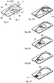
- the Figure 2B and 3B show an intermediate position of the moving element 40.1 or 40.2 between the first position P1 and a second position P2.
- the moving element 40.1 or 40.2 can only be rotated to a limited extent. Further intermediate positions are possible, since the movement element 40.1 or 40.2 can be moved continuously.
- the moving element 40.1 or 40.2 is in the second position P2, which is a middle position between the first end 31 and the second end 32.
- the movement element 40.1 or 40.2 can be rotated to a limited extent by the second angle of rotation ⁇ , which is, for example, less than 50 °.
- the Figure 2D and 3D show an intermediate position of the moving element 40.1 or 40.2 between the second position P2 and a third position P3.
- the movement element 40.1 or 40.2 is less rotatable than in the second position P2. Further intermediate positions are possible, since the movement element 40.1 or 40.2 can be moved continuously.
- the moving element 40.1 can only be rotated through a third angle of rotation ⁇ , which is smaller than the second angle of rotation ⁇ and which is, for example, 10 °.
- the moving element 40.1 or 40.2 is in the order of Figures 2A through 2E or 3A to 3E movable in the longitudinal direction x.
- the movement element 40.1 or 40.2 can also be moved counter to the longitudinal direction x.
- the seat unit 12 which is fastened to the movement element 40.1 or 40.2, is moved relative to the delimitation element 30 which is fastened to the seat foot 11.
- the first angle of rotation ⁇ , the second angle of rotation ⁇ and the third angle of rotation ⁇ depend on the position P1, P2, P3 of the movement element 40.1 or 40.2 in the longitudinal direction x.
- the third angle of rotation ⁇ in the third position P3 on the item of furniture 22 is smaller than the second angle of rotation ⁇ in the second position P2, which is spaced apart from the item of furniture 22.
- the second angle of rotation ⁇ is, in turn, smaller than the first angle of rotation ⁇ in the first position P1, which is at a greater distance from the piece of furniture 22 than the second position P2. This prevents the seat unit 12 from hitting the piece of furniture 22.
- a limiting element 30 and a movement element 40.1 or 40.2 is also possible in production technology and / or in the automation of processes in which objects or machines are not allowed to collide with other objects or machines.
Landscapes
- Engineering & Computer Science (AREA)
- Aviation & Aerospace Engineering (AREA)
- Transportation (AREA)
- Mechanical Engineering (AREA)
- Seats For Vehicles (AREA)
Abstract
Description
- Die Erfindung betrifft eine Sitzanordnung, ein Fahrzeug mit mindestens einer Sitzanordnung und ein Verfahren zur Steuerung einer Sitzanordnung.
- Es ist bekannt, dass Fahrzeugsitze für Personal, z.B. auch Fahrersitze, mehrere Bewegungen ausführen können. Diese Bewegungen umfassen eine Aufwärts- und eine Abwärtsbewegung, eine Vorwärts- und Rückwärtsbewegung sowie eine Rotationsbewegung um eine Längsachse des Fahrzeugsitzes. All diese Bewegungen sind voneinander unabhängig, und der Fahrersitz kann in jeder Position uneingeschränkt gedreht werden, wobei es keine Rolle spielt, ob sich der Sitz in einer vorderen, hinteren, oberen oder unteren Position befindet. Die Unabhängigkeit der Bewegungen voneinander führt dazu, dass z.B. ein Fahrersitz, der sich in einer vordersten Position befindet, bei einer Rotation z.B. gegen ein Fahrerpult stößt, z.B. mit einer Armlehne oder einer Rückenlehne.
- Die
CN 105774832 A beschreibt einen elektrischen Rotationsantrieb für einen Sitz in einem Hochgeschwindigkeitszug. Der Rotationsantrieb bewirkt eine automatische Drehung des Sitzes mit Hilfe einer Fernbedienung. Nachteilig ist hierbei, dass der Sitz ebenfalls z.B. mit einer Armlehne oder einer Rückenlehne an einen anderen Gegenstand im Hochgeschwindigkeitszug anstoßen kann. Außerdem ist lediglich eine rotatorische Bewegung des Sitzes beschrieben. - Die
EP 3 398 806 A1 offenbart eine Vorrichtung zum Rotieren eines Sitzes in einem Schienenfahrzeug, mit der ein Sitz entsprechend einer Fahrtrichtung ausgerichtet werden kann. Der Sitz ist um 180° drehbar. Die Vorrichtung umfasst Mittel zum Verriegeln und Entriegeln des Sitzes in einer ersten und in einer zweiten rotatorischen Endposition. Eine Steuerung des Sitzes erfolgt mit pneumatischen Mitteln. Ein Nachteil besteht darin, dass der Sitz nur in einer rotatorischen Richtung bewegt werden kann. - Der Erfindung liegt daher die Aufgabe zu Grunde, eine Sitzanordnung, ein Fahrzeug und ein Verfahren zu schaffen, wobei die Sitzanordnung in verschiedenen Richtungen bewegbar ist und wobei während einer Drehbewegung der Sitzanordnung ein Anstoßen an andere Gegenstände vermieden wird.
- Diese Aufgabe wird erfindungsgemäß mit einer Sitzanordnung nach Anspruch 1 gelöst. Weiterhin wird die Aufgabe mit einem Fahrzeug nach Anspruch 13 und einem Verfahren nach Anspruch 14 gelöst. Vorteilhafte Ausgestaltungen der Erfindung sind in den Unteransprüchen enthalten.
- Erfindungsgemäß besteht die Lösung der Aufgabe in einer Sitzanordnung zur Vermeidung einer Kollision mit einem weiteren Einrichtungsgegenstand in einer Umgebung der Sitzanordnung, wobei
- der Einrichtungsgegenstand an der Umgebung befestigt ist, und wobei
- die Sitzanordnung einen an einem Fußboden der Umgebung befestigten Sitzfuß und
- eine auf dem Sitzfuß angeordnete Sitzeinheit, die um eine Drehachse drehbar ist, umfasst, dadurch gekennzeichnet, dass
- die Sitzanordnung auch in einer Längsrichtung verschiebbar ist, wobei
- eine Drehung der Sitzeinheit um die Drehachse mit einer Verschiebung der Sitzeinheit in der Längsrichtung gekoppelt ist, und wobei
- ein Drehwinkel der Sitzeinheit von der Verschiebung der Sitzeinheit in der Längsrichtung abhängig ist.
- Ein Vorteil der erfindungsgemäßen Sitzanordnung besteht darin, dass die Sitzanordnung in verschiedenen Richtungen bewegbar ist, und dass während einer Drehbewegung der Sitzanordnung ein Anstoßen an andere Gegenstände vermieden wird. Weiterhin wird ein Einklemmen von Gegenständen, wie z.B. Kleidung, oder von Fingern vermieden. Wenn der Einrichtungsgegenstand z.B. ein Fahrerpult ist, können austauschbare Pultkanten entfallen und eine Herstellung des Fahrerpultes vereinfacht werden. Außerdem wird die Verschiebung der Sitzanordnung in der Längsrichtung mit der Drehung um die Drehachse verbunden, so dass diese voneinander abhängig sind. Die Drehbewegung wird in Abhängigkeit von einer Position der Sitzanordnung in der Längsrichtung eingeschränkt.
- Vorzugsweise beträgt ein erster Drehwinkel α der Sitzeinheit maximal 360°, wenn sich die Sitzeinheit in einer ersten Position entlang der Längsrichtung befindet. Die erste Position kann eine Endposition in der Längsrichtung sein, die in einer größtmöglichen Entfernung von dem Einrichtungsgegenstand liegt. In der ersten Position ist daher eine freie Bewegung um die Drehachse gegeben, wodurch ein Aufstehen bzw. Hinsetzen bei jedem beliebigen Drehwinkel möglich ist.
- Der Drehwinkel der Sitzeinheit kann in Abhängigkeit von der Verschiebung der Sitzeinheit in der Längsrichtung begrenzt sein, wobei der Drehwinkel insbesondere in Bezug auf einen Anstoßwinkel verringert ist, beispielsweise um 2°. Der Drehwinkel kann in Bezug auf den Anstoßwinkel beispielsweise auch um 5° verringert sein. Der Anstoßwinkel ist ein Winkel, bei dem ein Anstoßen der Sitzeinheit an den Einrichtungsgegenstand stattfinden würde. Durch die Begrenzung kann ein Anstoßen z.B. einer Armlehne und/oder einer Rückenlehne der Sitzeinheit an den Einrichtungsgegenstand vermieden werden.
- Insbesondere beträgt ein zweiter Drehwinkel der Sitzeinheit weniger als 50°, beispielsweise 48°, wenn sich die Sitzeinheit in einer zweiten Position entlang der Längsrichtung befindet. Die zweite Position ist z.B. eine mittlere Position in der Längsrichtung zwischen zwei Endpositionen. Eine Endposition entspricht der ersten Position, die am weitesten vom Einrichtungsgegenstand entfernt ist.
- Außerdem kann ein dritter Drehwinkel der Sitzeinheit weniger als 10°, beispielsweise 8°, betragen, wenn sich die Sitzeinheit in einer dritten Position entlang der Längsrichtung befindet. Die dritte Position kann eine Endposition in der Längsrichtung sein, die in einer größtmöglichen Nähe an dem Einrichtungsgegenstand liegt. In der dritten Position ist daher eine Bewegungsmöglichkeit in der Drehrichtung am geringsten. Dadurch wird ein Anstoßen der Sitzeinheit an den Einrichtungsgegenstand vermieden.
- Alternativ kann ein dritter Drehwinkel der Sitzeinheit 0° betragen, wenn sich die Sitzeinheit in einer dritten Position entlang der Längsrichtung befindet. In dieser Position ist also keine Drehbewegung möglich. Ein Nutzer der Sitzanordnung muss die Sitzeinheit entgegen der Längsrichtung verschieben, um die Sitzeinheit drehen zu können. Dadurch ist die Sitzeinheit in der dritten Position stabil in Bezug auf die Drehachse.
- Vorzugsweise ist an der Sitzeinheit ein Bewegungselement angeordnet, das innerhalb eines an dem Sitzfuß angeordneten Begrenzungselements begrenzt verschiebbar ist. Eine Kombination aus einem Bewegungselement und einem Begrenzungselement stellt eine einfach aufgebaute Struktur dar, mit der die Abhängigkeit einer Bewegung der Sitzeinheit um die Drehachse von einer Bewegung in der Längsrichtung ermöglicht wird.
- Speziell kann das Begrenzungselement eine stufenlose, zur Längsrichtung zumindest teilweise symmetrische und/oder zumindest teilweise asymmetrische Verjüngung von der ersten Position der Sitzeinheit bis hin zur dritten Position der Sitzeinheit aufweisen. Die Verjüngung bewirkt die Begrenzung der Drehbewegung der Sitzeinheit in Abhängigkeit von der Längsrichtung.
- Zudem kann das Begrenzungselement an einem ersten abgerundet sein und/oder an einem zweiten Ende eine zum ersten Ende hin offene Trapezform aufweisen. Das erste Ende und das zweite Ende bilden jeweils eine Führung für eine Bewegung des Bewegungselements.
- Weiterhin kann das Begrenzungselement dem Bewegungselement an dem zweiten Ende einen geringeren Drehwinkel ermöglichen als an dem ersten Ende. Dadurch ist gewährleistet, dass eine Drehbewegung in Abhängigkeit von der Längsrichtung veränderlich ist.
- Alternativ kann das Begrenzungselement an dem zweiten Ende eine Drehung des Bewegungselements verhindern. Das Bewegungselement ist dann stabil in Bezug auf die Drehachse, wodurch auch die Lage der Sitzeinheit um die Drehachse stabil ist.
- Zudem kann auch das Bewegungselement nockenförmig ausgebildet sein oder das Bewegungselement kann eine Kreisform mit einem Vorsprung aufweisen. Dadurch kann das Bewegungselement besonders gut in dem Begrenzungselement geführt werden.
- Weiterhin wird die Aufgabe mit einem Fahrzeug mit mindestens einer Sitzanordnung gelöst, wobei das Fahrzeug die Umgebung der Sitzanordnung ausbildet. Ein Fahrzeug ist besonders für einen Einbau der Sitzanordnung geeignet, weil in dem Fahrzeug Sitze benötigt werden, die am Fußboden befestigt sind.
- Außerdem wird die Aufgabe durch ein Verfahren zur Steuerung einer Sitzanordnung gelöst. Mindestens ein erster Sensor erfasst eine Position der Sitzeinheit entlang der Längsrichtung, ein zugehöriger Drehwinkel wird errechnet und eine Drehung der Sitzeinheit wird mittels einer Steuerung begrenzt. Auf diese Weise kann eine Steuerung der Sitzeinheit automatisiert durchgeführt werden.
- In einer speziellen Ausgestaltung der Erfindung erfasst mindestens ein zweiter Sensor eine Position, eine Geometrie, eine Veränderung der Position und/oder eine Veränderung der Geometrie des Einrichtungsgegenstands, und der Drehwinkel der Sitzeinheit wird an die Position, die Geometrie, die Veränderung der Position und/oder die Veränderung der Geometrie des Einrichtungsgegenstands angepasst. Somit können nicht nur die ursprüngliche Position und Geometrie des Einrichtungsgegenstands, sondern auch Veränderungen am Einrichtungsgegenstand berücksichtigt werden, z.B. wenn die Position des Einrichtungsgegenstands gegenüber der Sitzeinheit verändert wird oder wenn ein Gegenstand, beispielsweise ein Getränkehalter, am Einrichtungsgegenstand angebracht wird.
- Im Folgenden werden zwei Ausführungsbeispiele der Erfindung anhand von dreizehn Figuren näher erläutert. Es zeigen:
- Fig. 1
- eine schematische Schnittansicht einer erfindungsgemäßen Sitzanordnung,
- Fig. 2
- eine schematische, perspektivische Darstellung eines Begrenzungselements und eines Bewegungselements der erfindungsgemäßen Sitzanordnung in
Fig. 1 gemäß einem ersten Ausführungsbeispiel, - Fig. 2A bis 2E
- verschiedene schematische Positionen und Drehwinkel des Bewegungselements in
Fig. 2 , - Fig. 3
- eine schematische, perspektivische Darstellung eines Begrenzungselements und eines Bewegungselements der erfindungsgemäßen Sitzanordnung in
Fig. 1 gemäß einem zweiten Ausführungsbeispiel und - Fig. 3A bis 3E
- verschiedene schematische Positionen und Drehwinkel des Bewegungselements in
Fig. 3 . -
Fig. 1 zeigt eine erfindungsgemäße Sitzanordnung 10 in einer Umgebung 20, die hier einem Fahrzeug bzw. einem Schienenfahrzeug entspricht. Eine Sitzanordnung 10 kann sich beispielsweise in einem Zugbegleiterabteil und/oder in einem Zugführerraum eines Schienenfahrzeugs befinden. Weitere Einsatzmöglichkeiten, auch in anderen Arten von Fahrzeugen, wie z.B. in LKW oder Bussen, in Schiffen, Flugzeugen und sogar in der Luft- und Raumfahrt sind denkbar. Die Sitzanordnung 10 kann sich dann in einem Cockpit befinden. Außerdem ist ein Einsatz der Sitzeinrichtung in Baumaschinen oder Gebäuden, z.B. in Laboren oder Kontrollräumen möglich. Die Umgebung 20 umfasst zusätzlich zur Sitzanordnung 10 einen Fußboden 21 und einen Einrichtungsgegenstand 22, der beispielsweise ein Tisch sein kann. Als Einrichtungsgegenstand 22 ist auch ein Fahrerpult des Fahrzeugs denkbar. - Die Sitzanordnung 10 umfasst einen Sitzfuß 11, eine Sitzeinheit 12 und ein Begrenzungselement 30, in dem ein Bewegungselement 40.1, 40.2 angeordnet ist, vgl.
Fig. 2 bis 2E und3 bis 3E . Die Sitzeinheit 12 umfasst eine Sitzfläche 13, eine Armlehne 14 und eine Rückenlehne 15. Eine Längsrichtung x definiert eine Bewegungsrichtung des Bewegungselements 40.1 bzw. 40.2. - In den
Fig. 2 bis 2E und3 bis 3E sind das Begrenzungselement 30 und das Bewegungselement 40.1 bzw. 40.2 gemeinsam, aber ansonsten von der Sitzanordnung 10 isoliert, dargestellt. Die Bezugszeichen inFig. 2 gelten für dieFig. 2A bis 2E gleichermaßen. Die Bezugszeichen inFig. 3 gelten für dieFig. 3A bis 3E gleichermaßen. - In den
Fig. 2 und3 weist das Begrenzungselement 30 in der Längsrichtung x ein erstes Ende 31 und ein zweites Ende 32 auf. Außerdem umfasst das Begrenzungselement 30 eine Verjüngung 33 in der Längsrichtung. - Das Bewegungselement 40.1 bzw. 40.2 weist eine Drehachse D auf. In
Fig. 2 umfasst das Bewegungselement 40.1 eine Kreisform 41 mit einem Vorsprung 42. InFig. 3 ist das Bewegungselement 40.2 nockenförmig. - In den
Fig. 2 und 2A sowie 3 und 3A befindet sich das Bewegungselement 40.1 bzw. 40.2 in einer ersten Position P1 und ist um einen ersten Drehwinkel α = 360° drehbar. - Die
Fig. 2B und3B zeigen eine Zwischenposition des Bewegungselement 40.1 bzw. 40.2 zwischen der ersten Position P1 und einer zweiten Position P2. In der Zwischenposition ist das Bewegungselement 40.1 bzw. 40.2 nur noch begrenzt drehbar. Weitere Zwischenpositionen sind möglich, da das Bewegungselement 40.1 bzw. 40.2 stufenlos bewegbar ist. - In den
Fig. 2C und3C befindet sich das Bewegungselement 40.1 bzw. 40.2 in der zweiten Position P2, die eine mittlere Position zwischen dem ersten Ende 31 und dem zweiten Ende 32 ist. Hier ist das Bewegungselement 40.1 bzw. 40.2 begrenzt um den zweiten Drehwinkel β drehbar, der beispielsweise kleiner als 50° ist. - Die
Fig. 2D und3D zeigen eine Zwischenposition des Bewegungselement 40.1 bzw. 40.2 zwischen der zweiten Position P2 und einer dritten Position P3. In der Zwischenposition ist das Bewegungselement 40.1 bzw. 40.2 weniger drehbar als in der zweiten Position P2. Weitere Zwischenpositionen sind möglich, da das Bewegungselement 40.1 bzw. 40.2 stufenlos bewegbar ist. - In
Fig. 2E ist das Bewegungselement 40.1 nur noch um einen dritten Drehwinkel γ drehbar, der kleiner ist als der zweite Drehwinkel β und der beispielsweise 10° beträgt. - In
Fig. 3E ist das Bewegungselement 40.2 nicht mehr drehbar, d.h. der dritte Drehwinkel γ beträgt 0°. - Das Bewegungselement 40.1 bzw. 40.2 ist in der Reihenfolge der
Fig. 2A bis 2E bzw. 3A bis 3E in der Längsrichtung x bewegbar. Selbstverständlich ist das Bewegungselement 40.1 bzw. 40.2 auch entgegen der Längsrichtung x bewegbar. - Im Betrieb wird die Sitzeinheit 12, die am Bewegungselement 40.1 bzw. 40.2 befestigt ist, relativ zum Begrenzungselement 30, das am Sitzfuß 11 befestigt ist, bewegt. Der erste Drehwinkel α, der zweite Drehwinkel β und der dritte Drehwinkel γ hängen dabei von der Position P1, P2, P3 des Bewegungselements 40.1 bzw. 40.2 in der Längsrichtung x ab. Dadurch ist der dritte Drehwinkel γ in der dritten Position P3 am Einrichtungsgegenstand 22 kleiner als der zweite Drehwinkel β in der zweiten Position P2, die vom Einrichtungsgegenstand 22 beabstandet ist. Der zweite Drehwinkel β wiederum ist kleiner als der erste Drehwinkel α in der ersten Position P1, die vom Einrichtungsgegenstand 22 weiter beabstandet ist als die zweite Position P2. Dadurch wird ein Anstoßen der Sitzeinheit 12 an den Einrichtungsgegenstand 22 vermieden.
- Die Kombination aus einem Begrenzungselement 30 und einem Bewegungselement 40.1 bzw. 40.2 ist auch in der Produktionstechnik und/oder bei einer Automatisierung von Abläufen möglich, bei denen Gegenstände oder Maschinen nicht gegen andere Gegenstände oder Maschinen stoßen dürfen.
-
- 10
- Sitzanordnung
- 11
- Sitzfuß
- 12
- Sitzeinheit
- 13
- Sitzfläche
- 14
- Armlehne
- 15
- Rückenlehne
- 20
- Umgebung
- 21
- Fußboden
- 22
- Einrichtungsgegenstand
- 30
- Begrenzungselement
- 31
- Erstes Ende
- 32
- Zweites Ende
- 33
- Verjüngung
- 40.1
- Bewegungselement
- 40.2
- Bewegungselement
- 41
- Kreisform
- 42
- Vorsprung
- x
- Längsrichtung
- P1
- Erste Position
- P2
- Zweite Position
- P3
- Dritte Position
- D
- Drehachse
- α
- Erster Drehwinkel
- β
- Zweiter Drehwinkel
- γ
- Dritter Drehwinkel
Claims (15)
- Sitzanordnung (10) zur Vermeidung einer Kollision mit einem weiteren Einrichtungsgegenstand (22) in einer Umgebung (20) der Sitzanordnung (10), wobei- der Einrichtungsgegenstand (22) an der Umgebung (20) befestigt ist, und wobei- die Sitzanordnung (10) einen an einem Fußboden (21) der Umgebung (20) befestigten Sitzfuß (11) und- eine auf dem Sitzfuß (11) angeordnete Sitzeinheit (12), die um eine Drehachse (D) drehbar ist, umfasst,
dadurch gekennzeichnet, dass- die Sitzanordnung (10) auch in einer Längsrichtung (x) verschiebbar ist, wobei- eine Drehung der Sitzeinheit (12) um die Drehsachse (D) mit einer Verschiebung der Sitzeinheit (12) in der Längsrichtung (x) gekoppelt ist, und wobei- ein Drehwinkel (α, β, γ) der Sitzeinheit (12) von der Verschiebung der Sitzeinheit (12) in der Längsrichtung (x) abhängig ist. - Sitzanordnung (10) nach Anspruch 1, dadurch gekennzeichnet, dass ein erster Drehwinkel (α) der Sitzeinheit (12) maximal 360° beträgt, wenn sich die Sitzeinheit (12) in einer ersten Position (P1) entlang der Längsrichtung (x) befindet.
- Sitzanordnung (10) nach Anspruch 1 oder 2, dadurch gekennzeichnet, dass der Drehwinkel (β, γ) der Sitzeinheit (12) in Abhängigkeit von der Verschiebung der Sitzeinheit (12) in der Längsrichtung (x) begrenzt ist, wobei der Drehwinkel (β, γ) insbesondere in Bezug auf einen Anstoßwinkel verringert ist, beispielweise um 2°.
- Sitzanordnung (10) nach Anspruch 3, dadurch gekennzeichnet, dass ein zweiter Drehwinkel (β) der Sitzeinheit (12) weniger als 50°, beispielsweise 48°, beträgt, wenn sich die Sitzeinheit (12) in einer zweiten Position (P2) entlang der Längsrichtung (x) befindet.
- Sitzanordnung (10) nach Anspruch 3 oder 4, dadurch gekennzeichnet, dass ein dritter Drehwinkel (γ) der Sitzeinheit (12) weniger als 10°, beispielsweise 8°, beträgt, wenn sich die Sitzeinheit (12) in einer dritten Position (P3) entlang der Längsrichtung (x) befindet.
- Sitzanordnung (10) nach einem der Ansprüche 3 bis 5, dadurch gekennzeichnet, dass ein dritter Drehwinkel (γ) der Sitzeinheit 0° beträgt, wenn sich die Sitzeinheit (12) in einer dritten Position (P3) entlang der Längsrichtung (x) befindet.
- Sitzanordnung (10) nach einem der vorhergehenden Ansprüche, dadurch gekennzeichnet, dass an der Sitzeinheit (12) ein Bewegungselement (40.1, 40.2) angeordnet ist, das innerhalb eines an dem Sitzfuß (11) angeordneten Begrenzungselements (30) begrenzt verschiebbar ist.
- Sitzanordnung (10) nach Anspruch 7, dadurch gekennzeichnet, dass das Begrenzungselement (30) eine stufenlose, zur Längsrichtung (x) zumindest teilweise symmetrische und/oder eine zumindest teilweise asymmetrische Verjüngung (33) von der ersten Position (P1) der Sitzeinheit (12) bis hin zur dritten Position (P3) der Sitzeinheit (12) aufweist.
- Sitzanordnung (10) nach Anspruch 7 oder 8, dadurch gekennzeichnet, dass das Begrenzungselement (30) an einem ersten Ende (31) abgerundet ist und/oder an einem zweiten Ende (32) eine zum ersten Ende (31) hin offene Trapezform aufweist.
- Sitzanordnung (10) nach Anspruch 9, dadurch gekennzeichnet, dass das Begrenzungselement (30) dem Bewegungselement (40.1) an dem zweiten Ende (32) einen geringeren Drehwinkel (γ) ermöglicht als an dem ersten Ende (31).
- Sitzanordnung (10) nach Anspruch 9 oder 10, dadurch gekennzeichnet, dass das Begrenzungselement (30) an dem zweiten Ende (32) eine Drehung des Bewegungselements (40.2) verhindert.
- Sitzanordnung (10) nach einem der Ansprüche 7 bis 11, dadurch gekennzeichnet, dass das Bewegungselement (40.2) nockenförmig ausgebildet ist oder dass das Bewegungselement (40.1) eine Kreisform mit einem Vorsprung aufweist.
- Fahrzeug mit mindestens einer Sitzanordnung (10) nach einem der Ansprüche 1 bis 12, wobei das Fahrzeug die Umgebung (20) der Sitzanordnung (10) ausbildet.
- Verfahren zur Steuerung einer Sitzanordnung (10) nach einem der Ansprüche 1 bis 12, dadurch gekennzeichnet, dass mindestens ein erster Sensor eine Position (P1, P2, P3) der Sitzeinheit (12) entlang der Längsrichtung (x) erfasst, ein zugehöriger Drehwinkel (α, β, γ) errechnet wird und eine Drehung der Sitzeinheit (12) mittels einer Steuerung begrenzt wird.
- Verfahren nach Anspruch 14, dadurch gekennzeichnet, dass mindestens ein zweiter Sensor eine Position, eine Geometrie, eine Veränderung der Position und/oder eine Veränderung der Geometrie des Einrichtungsgegenstands (22) erfasst und der Drehwinkel (α, β, γ) der Sitzeinheit (12) an die Position, die Geometrie, die Veränderung der Position und/oder die Veränderung der Geometrie des Einrichtungsgegenstands (22) angepasst wird.
Applications Claiming Priority (1)
| Application Number | Priority Date | Filing Date | Title |
|---|---|---|---|
| DE102019134374.7A DE102019134374A1 (de) | 2019-12-13 | 2019-12-13 | Sitzanordnung, Fahrzeug mit mindestens einer Sitzanordnung und Verfahren zur Steuerung einer Sitzanordnung |
Publications (2)
| Publication Number | Publication Date |
|---|---|
| EP3835119A1 true EP3835119A1 (de) | 2021-06-16 |
| EP3835119B1 EP3835119B1 (de) | 2025-09-17 |
Family
ID=73475876
Family Applications (1)
| Application Number | Title | Priority Date | Filing Date |
|---|---|---|---|
| EP20208162.6A Active EP3835119B1 (de) | 2019-12-13 | 2020-11-17 | Sitzanordnung, fahrzeug mit mindestens einer sitzanordnung und verfahren zur steuerung einer sitzanordnung |
Country Status (2)
| Country | Link |
|---|---|
| EP (1) | EP3835119B1 (de) |
| DE (1) | DE102019134374A1 (de) |
Cited By (1)
| Publication number | Priority date | Publication date | Assignee | Title |
|---|---|---|---|---|
| EP4385811A1 (de) * | 2022-12-14 | 2024-06-19 | AGCO International GmbH | Fahrzeugschwenksitze |
Families Citing this family (1)
| Publication number | Priority date | Publication date | Assignee | Title |
|---|---|---|---|---|
| DE102023113094B4 (de) * | 2023-05-17 | 2025-07-24 | Grammer Aktiengesellschaft | Fahrzeugsitz |
Citations (6)
| Publication number | Priority date | Publication date | Assignee | Title |
|---|---|---|---|---|
| US20060255640A1 (en) * | 2003-02-19 | 2006-11-16 | Hiroki Kusanagi | Seat for vehicle |
| US20080290706A1 (en) * | 2007-05-25 | 2008-11-27 | Aisin Seiki Kabushiki Kaisha | Seat position adjusting apparatus for vehicle |
| CN105774832A (zh) | 2016-05-12 | 2016-07-20 | 湖北韵生航天科技有限公司 | 一种用于高列座椅的电动旋转驱动器 |
| DE102015212459A1 (de) * | 2015-07-02 | 2017-01-05 | Hamm Ag | Sitz für eine Baumaschine, sowie Baumaschine |
| DE102016123240A1 (de) * | 2016-12-01 | 2018-06-07 | Aguti Produktentwicklung & Design Gmbh | Vorrichtung für ein Fahrzeugsitz mit einer Dreheinheit und einer Verschiebeeinheit |
| EP3398806A1 (de) | 2017-05-04 | 2018-11-07 | ALSTOM Transport Technologies | Gesicherte vorrichtung zum drehen eines sitzes, insbesondere für ein schienenfahrzeug |
Family Cites Families (3)
| Publication number | Priority date | Publication date | Assignee | Title |
|---|---|---|---|---|
| JP3444259B2 (ja) * | 2000-03-03 | 2003-09-08 | トヨタ車体株式会社 | 車両用シート装置 |
| TWM328973U (en) * | 2007-08-16 | 2008-03-21 | Pro Glory Entpr Co Ltd | Vehicle seat adjusting apparatus |
| DE102013227013B4 (de) * | 2013-12-20 | 2022-09-29 | Volkswagen Aktiengesellschaft | Sitzvorrichtung, Fahrgastraum, Fahrzeug |
-
2019
- 2019-12-13 DE DE102019134374.7A patent/DE102019134374A1/de active Pending
-
2020
- 2020-11-17 EP EP20208162.6A patent/EP3835119B1/de active Active
Patent Citations (6)
| Publication number | Priority date | Publication date | Assignee | Title |
|---|---|---|---|---|
| US20060255640A1 (en) * | 2003-02-19 | 2006-11-16 | Hiroki Kusanagi | Seat for vehicle |
| US20080290706A1 (en) * | 2007-05-25 | 2008-11-27 | Aisin Seiki Kabushiki Kaisha | Seat position adjusting apparatus for vehicle |
| DE102015212459A1 (de) * | 2015-07-02 | 2017-01-05 | Hamm Ag | Sitz für eine Baumaschine, sowie Baumaschine |
| CN105774832A (zh) | 2016-05-12 | 2016-07-20 | 湖北韵生航天科技有限公司 | 一种用于高列座椅的电动旋转驱动器 |
| DE102016123240A1 (de) * | 2016-12-01 | 2018-06-07 | Aguti Produktentwicklung & Design Gmbh | Vorrichtung für ein Fahrzeugsitz mit einer Dreheinheit und einer Verschiebeeinheit |
| EP3398806A1 (de) | 2017-05-04 | 2018-11-07 | ALSTOM Transport Technologies | Gesicherte vorrichtung zum drehen eines sitzes, insbesondere für ein schienenfahrzeug |
Cited By (2)
| Publication number | Priority date | Publication date | Assignee | Title |
|---|---|---|---|---|
| EP4385811A1 (de) * | 2022-12-14 | 2024-06-19 | AGCO International GmbH | Fahrzeugschwenksitze |
| US12522113B2 (en) | 2022-12-14 | 2026-01-13 | Agco International Gmbh | Vehicle swiveling seats |
Also Published As
| Publication number | Publication date |
|---|---|
| DE102019134374A1 (de) | 2021-06-17 |
| EP3835119B1 (de) | 2025-09-17 |
Similar Documents
| Publication | Publication Date | Title |
|---|---|---|
| EP2746100B1 (de) | Nutzfahrzeugsitz mit einem Verriegelungselement | |
| EP2734405B1 (de) | Fahrzeugsitz | |
| DE102004044970B4 (de) | Kopfstützenanordnung mit Nockenantrieb in vier Richtungen | |
| EP3194203B1 (de) | Fahrzeugsitz | |
| EP3642073B1 (de) | Sitz für ein kraftfahrzeug | |
| DE102014201633A1 (de) | Verstellsystem für einen Sitz sowie Sitz | |
| DE102015212459A1 (de) | Sitz für eine Baumaschine, sowie Baumaschine | |
| DE102016204067A1 (de) | Vorrichtung zum Verstellen zumindest einer Seitenwange eines Sitzteils und/oder einer Rückenlehne eines Fahrzeugsitzes | |
| EP3263396B1 (de) | Federungsvorrichtung | |
| DE112015003087T5 (de) | Kopfstützenverstellmodul | |
| EP4139163B1 (de) | Fahrzeugsitz mit einem kinematikhebel | |
| EP3330122B1 (de) | Vorrichtung für ein fahrzeugsitz mit einer dreheinheit und einer verschiebeeinheit | |
| EP3835119B1 (de) | Sitzanordnung, fahrzeug mit mindestens einer sitzanordnung und verfahren zur steuerung einer sitzanordnung | |
| DE102024002956A1 (de) | Displayanordnung für einen Kraftwagen sowie Kraftwagen mit einer Displayanordnung | |
| DE102014016225B4 (de) | Verfahren zum Betreiben einer Anzeigeeinrichtung eines Kraftwagens und Anzeigesystem für einen Kraftwagen sowie Kraftwagen mit einem Anzeigesystem | |
| DE3243747C2 (de) | ||
| DE60132146T2 (de) | Mehrfach positionierbare Kopfstütze und Sitz mit einer solchen Kopfstütze | |
| EP2360051A2 (de) | Fahrzeugsitz mit einem Sitzversteller | |
| DE19915469B4 (de) | Armlehne für eine Fahrzeugmittelkonsole | |
| EP3819164B1 (de) | Fahrzeugausstattungsvorrichtung | |
| EP2567860A1 (de) | Montagevorrichtung für einen Fahrzeugsitz sowie Fahrzeugsitz | |
| DE102018207036B4 (de) | Höhenverstellbare Armlehne mit motorisierter Antriebseinrichtung und Kraftfahrzeug mit einer solchen Armlehne | |
| EP3835120B1 (de) | Sitzvorrichtung für eine baumaschine | |
| EP3710334B1 (de) | Lenksäule für ein kraftfahrzeug | |
| WO2020229135A1 (de) | Körperadaptive armauflagenanordnung |
Legal Events
| Date | Code | Title | Description |
|---|---|---|---|
| PUAI | Public reference made under article 153(3) epc to a published international application that has entered the european phase |
Free format text: ORIGINAL CODE: 0009012 |
|
| STAA | Information on the status of an ep patent application or granted ep patent |
Free format text: STATUS: THE APPLICATION HAS BEEN PUBLISHED |
|
| AK | Designated contracting states |
Kind code of ref document: A1 Designated state(s): AL AT BE BG CH CY CZ DE DK EE ES FI FR GB GR HR HU IE IS IT LI LT LU LV MC MK MT NL NO PL PT RO RS SE SI SK SM TR |
|
| STAA | Information on the status of an ep patent application or granted ep patent |
Free format text: STATUS: REQUEST FOR EXAMINATION WAS MADE |
|
| 17P | Request for examination filed |
Effective date: 20211209 |
|
| RBV | Designated contracting states (corrected) |
Designated state(s): AL AT BE BG CH CY CZ DE DK EE ES FI FR GB GR HR HU IE IS IT LI LT LU LV MC MK MT NL NO PL PT RO RS SE SI SK SM TR |
|
| STAA | Information on the status of an ep patent application or granted ep patent |
Free format text: STATUS: EXAMINATION IS IN PROGRESS |
|
| 17Q | First examination report despatched |
Effective date: 20230317 |
|
| RAP1 | Party data changed (applicant data changed or rights of an application transferred) |
Owner name: ALSTOM HOLDINGS |
|
| P01 | Opt-out of the competence of the unified patent court (upc) registered |
Effective date: 20230822 |
|
| GRAP | Despatch of communication of intention to grant a patent |
Free format text: ORIGINAL CODE: EPIDOSNIGR1 |
|
| STAA | Information on the status of an ep patent application or granted ep patent |
Free format text: STATUS: GRANT OF PATENT IS INTENDED |
|
| INTG | Intention to grant announced |
Effective date: 20250410 |
|
| GRAS | Grant fee paid |
Free format text: ORIGINAL CODE: EPIDOSNIGR3 |
|
| GRAA | (expected) grant |
Free format text: ORIGINAL CODE: 0009210 |
|
| STAA | Information on the status of an ep patent application or granted ep patent |
Free format text: STATUS: THE PATENT HAS BEEN GRANTED |
|
| AK | Designated contracting states |
Kind code of ref document: B1 Designated state(s): AL AT BE BG CH CY CZ DE DK EE ES FI FR GB GR HR HU IE IS IT LI LT LU LV MC MK MT NL NO PL PT RO RS SE SI SK SM TR |
|
| REG | Reference to a national code |
Ref country code: GB Ref legal event code: FG4D Free format text: NOT ENGLISH |
|
| REG | Reference to a national code |
Ref country code: CH Ref legal event code: EP |
|
| REG | Reference to a national code |
Ref country code: DE Ref legal event code: R096 Ref document number: 502020011930 Country of ref document: DE |
|
| REG | Reference to a national code |
Ref country code: IE Ref legal event code: FG4D Free format text: LANGUAGE OF EP DOCUMENT: GERMAN |
|
| PG25 | Lapsed in a contracting state [announced via postgrant information from national office to epo] |
Ref country code: NO Free format text: LAPSE BECAUSE OF FAILURE TO SUBMIT A TRANSLATION OF THE DESCRIPTION OR TO PAY THE FEE WITHIN THE PRESCRIBED TIME-LIMIT Effective date: 20251217 |
|
| REG | Reference to a national code |
Ref country code: LT Ref legal event code: MG9D |
|
| PG25 | Lapsed in a contracting state [announced via postgrant information from national office to epo] |
Ref country code: FI Free format text: LAPSE BECAUSE OF FAILURE TO SUBMIT A TRANSLATION OF THE DESCRIPTION OR TO PAY THE FEE WITHIN THE PRESCRIBED TIME-LIMIT Effective date: 20250917 |
|
| PG25 | Lapsed in a contracting state [announced via postgrant information from national office to epo] |
Ref country code: HR Free format text: LAPSE BECAUSE OF FAILURE TO SUBMIT A TRANSLATION OF THE DESCRIPTION OR TO PAY THE FEE WITHIN THE PRESCRIBED TIME-LIMIT Effective date: 20250917 |
|
| PG25 | Lapsed in a contracting state [announced via postgrant information from national office to epo] |
Ref country code: GR Free format text: LAPSE BECAUSE OF FAILURE TO SUBMIT A TRANSLATION OF THE DESCRIPTION OR TO PAY THE FEE WITHIN THE PRESCRIBED TIME-LIMIT Effective date: 20251218 |
|
| PG25 | Lapsed in a contracting state [announced via postgrant information from national office to epo] |
Ref country code: SE Free format text: LAPSE BECAUSE OF FAILURE TO SUBMIT A TRANSLATION OF THE DESCRIPTION OR TO PAY THE FEE WITHIN THE PRESCRIBED TIME-LIMIT Effective date: 20250917 |
|
| REG | Reference to a national code |
Ref country code: NL Ref legal event code: MP Effective date: 20250917 |
|
| PG25 | Lapsed in a contracting state [announced via postgrant information from national office to epo] |
Ref country code: LV Free format text: LAPSE BECAUSE OF FAILURE TO SUBMIT A TRANSLATION OF THE DESCRIPTION OR TO PAY THE FEE WITHIN THE PRESCRIBED TIME-LIMIT Effective date: 20250917 |
|
| PG25 | Lapsed in a contracting state [announced via postgrant information from national office to epo] |
Ref country code: BG Free format text: LAPSE BECAUSE OF FAILURE TO SUBMIT A TRANSLATION OF THE DESCRIPTION OR TO PAY THE FEE WITHIN THE PRESCRIBED TIME-LIMIT Effective date: 20250917 |
|
| PG25 | Lapsed in a contracting state [announced via postgrant information from national office to epo] |
Ref country code: RS Free format text: LAPSE BECAUSE OF FAILURE TO SUBMIT A TRANSLATION OF THE DESCRIPTION OR TO PAY THE FEE WITHIN THE PRESCRIBED TIME-LIMIT Effective date: 20251217 |
|
| PG25 | Lapsed in a contracting state [announced via postgrant information from national office to epo] |
Ref country code: NL Free format text: LAPSE BECAUSE OF FAILURE TO SUBMIT A TRANSLATION OF THE DESCRIPTION OR TO PAY THE FEE WITHIN THE PRESCRIBED TIME-LIMIT Effective date: 20250917 |
|
| PG25 | Lapsed in a contracting state [announced via postgrant information from national office to epo] |
Ref country code: SM Free format text: LAPSE BECAUSE OF FAILURE TO SUBMIT A TRANSLATION OF THE DESCRIPTION OR TO PAY THE FEE WITHIN THE PRESCRIBED TIME-LIMIT Effective date: 20250917 |
|
| PG25 | Lapsed in a contracting state [announced via postgrant information from national office to epo] |
Ref country code: ES Free format text: LAPSE BECAUSE OF FAILURE TO SUBMIT A TRANSLATION OF THE DESCRIPTION OR TO PAY THE FEE WITHIN THE PRESCRIBED TIME-LIMIT Effective date: 20250917 |
|
| PG25 | Lapsed in a contracting state [announced via postgrant information from national office to epo] |
Ref country code: IT Free format text: LAPSE BECAUSE OF FAILURE TO SUBMIT A TRANSLATION OF THE DESCRIPTION OR TO PAY THE FEE WITHIN THE PRESCRIBED TIME-LIMIT Effective date: 20250917 Ref country code: RO Free format text: LAPSE BECAUSE OF FAILURE TO SUBMIT A TRANSLATION OF THE DESCRIPTION OR TO PAY THE FEE WITHIN THE PRESCRIBED TIME-LIMIT Effective date: 20250917 |
|
| PG25 | Lapsed in a contracting state [announced via postgrant information from national office to epo] |
Ref country code: IS Free format text: LAPSE BECAUSE OF FAILURE TO SUBMIT A TRANSLATION OF THE DESCRIPTION OR TO PAY THE FEE WITHIN THE PRESCRIBED TIME-LIMIT Effective date: 20260117 |
|
| PG25 | Lapsed in a contracting state [announced via postgrant information from national office to epo] |
Ref country code: CZ Free format text: LAPSE BECAUSE OF FAILURE TO SUBMIT A TRANSLATION OF THE DESCRIPTION OR TO PAY THE FEE WITHIN THE PRESCRIBED TIME-LIMIT Effective date: 20250917 Ref country code: PT Free format text: LAPSE BECAUSE OF FAILURE TO SUBMIT A TRANSLATION OF THE DESCRIPTION OR TO PAY THE FEE WITHIN THE PRESCRIBED TIME-LIMIT Effective date: 20260119 |
|
| PG25 | Lapsed in a contracting state [announced via postgrant information from national office to epo] |
Ref country code: PL Free format text: LAPSE BECAUSE OF FAILURE TO SUBMIT A TRANSLATION OF THE DESCRIPTION OR TO PAY THE FEE WITHIN THE PRESCRIBED TIME-LIMIT Effective date: 20250917 |
|
| PG25 | Lapsed in a contracting state [announced via postgrant information from national office to epo] |
Ref country code: EE Free format text: LAPSE BECAUSE OF FAILURE TO SUBMIT A TRANSLATION OF THE DESCRIPTION OR TO PAY THE FEE WITHIN THE PRESCRIBED TIME-LIMIT Effective date: 20250917 Ref country code: SK Free format text: LAPSE BECAUSE OF FAILURE TO SUBMIT A TRANSLATION OF THE DESCRIPTION OR TO PAY THE FEE WITHIN THE PRESCRIBED TIME-LIMIT Effective date: 20250917 |