EP3834986A1 - Sanding machine provided with an auxiliary device to facilitate mounting an abrasive belt - Google Patents
Sanding machine provided with an auxiliary device to facilitate mounting an abrasive belt Download PDFInfo
- Publication number
- EP3834986A1 EP3834986A1 EP20210045.9A EP20210045A EP3834986A1 EP 3834986 A1 EP3834986 A1 EP 3834986A1 EP 20210045 A EP20210045 A EP 20210045A EP 3834986 A1 EP3834986 A1 EP 3834986A1
- Authority
- EP
- European Patent Office
- Prior art keywords
- sanding
- sanding machine
- abrasive belt
- auxiliary device
- advancing
- Prior art date
- Legal status (The legal status is an assumption and is not a legal conclusion. Google has not performed a legal analysis and makes no representation as to the accuracy of the status listed.)
- Granted
Links
Images


Classifications
-
- B—PERFORMING OPERATIONS; TRANSPORTING
- B24—GRINDING; POLISHING
- B24B—MACHINES, DEVICES, OR PROCESSES FOR GRINDING OR POLISHING; DRESSING OR CONDITIONING OF ABRADING SURFACES; FEEDING OF GRINDING, POLISHING, OR LAPPING AGENTS
- B24B21/00—Machines or devices using grinding or polishing belts; Accessories therefor
- B24B21/04—Machines or devices using grinding or polishing belts; Accessories therefor for grinding plane surfaces
-
- B—PERFORMING OPERATIONS; TRANSPORTING
- B24—GRINDING; POLISHING
- B24B—MACHINES, DEVICES, OR PROCESSES FOR GRINDING OR POLISHING; DRESSING OR CONDITIONING OF ABRADING SURFACES; FEEDING OF GRINDING, POLISHING, OR LAPPING AGENTS
- B24B21/00—Machines or devices using grinding or polishing belts; Accessories therefor
- B24B21/18—Accessories
-
- B—PERFORMING OPERATIONS; TRANSPORTING
- B24—GRINDING; POLISHING
- B24B—MACHINES, DEVICES, OR PROCESSES FOR GRINDING OR POLISHING; DRESSING OR CONDITIONING OF ABRADING SURFACES; FEEDING OF GRINDING, POLISHING, OR LAPPING AGENTS
- B24B21/00—Machines or devices using grinding or polishing belts; Accessories therefor
- B24B21/18—Accessories
- B24B21/20—Accessories for controlling or adjusting the tracking or the tension of the grinding belt
Definitions
- the present invention relates to a sanding machine provided with an auxiliary device to facilitate mounting an abrasive belt.
- the invention relates to a sanding machine provided with an auxiliary device for facilitating the assembly, by an operator, of a closed-loop abrasive belt for sanding panels, arranged transversely with respect to the advancing direction of the panels to be machined.
- the assembly of the closed-looped abrasive belts transversal to the advancing direction of the panels to be machined is carried out by the operators in a completely manual way by winding, in sequence, a portion of the belt on a first pulley and the opposite portion of the same belt on the opposite pulley.
- Another object of the invention is to provide a sanding machine equipped with an auxiliary device to facilitate the assembly of an abrasive belt, which is polyvalent, i.e., which can be adapted to different types of sanding machines.
- a further object of the present invention is to provide a sanding machine equipped with an auxiliary device to facilitate the assembly of an abrasive belt, which is not complex from the structural point of view.
- a sanding machine for sanding panels or similar items, comprising: advancing means for advancing, in use, at least one panel or similar item according to a predetermined advancing direction; at least one sanding device for sanding, in use, at least one panel or similar item during the advancement of said at least one panel or similar item according to said predetermined advancing direction, said at least one sanding device comprising a removable abrasive belt, directed transversely to said predetermined advancing direction; and at least one auxiliary device to promote, in use, fitting of said abrasive belt, by an operator, in said at least one sanding device, said at least one auxiliary device comprising movement means for moving, in use, at least one portion of said abrasive belt transversely to said predetermined advancing direction from a first position, which is reachable by an operator and adjacent to a first outer edge of said sanding machine, to a second position reachable by an operator and adjacent to a
- an advancing surface may be provided on which said advancing means advances, in use, said at least one panel or similar item according to said advancing direction
- said movement means may be configured for moving, in use, said at least one portion of said abrasive belt transversely to a second surface arranged orthogonally to said advancing surface according to said advancing direction, and in that said at least one abrasive belt may be directed transversely to said second surface.
- said at least one sanding device comprises a driven pulley and a drive pulley and in that said at least one abrasive belt has a loop shape so as to be windable on said driven pulley and on said drive pulley.
- said movement means may comprise a guide element, a movable member movably engaged with said guide element, and a gripping element connected to said movable member and configured for gripping, in use, said at least one portion of said abrasive belt.
- said gripping element may be movable between a substantially vertical position and a substantially horizontal position.
- said gripping element may be rotatable in a vertical direction.
- said guide element may be a substantially rectilinear guide.
- said at least one auxiliary device may face said at least one sanding device.
- said at least one sanding device and said at least one auxiliary device may be arranged below said advancing surface, and in that said sanding machine comprises at least one component that is movable between a raised position, wherein said at least one component is interposed between said at least one sanding device and said at least one auxiliary device, and a lowered position, in which said at least one component is arranged below said at least one sanding device and said at least one auxiliary device.
- the numerical reference 1 indicates a first sanding machine according to the invention, comprising a conveyor belt 2 to allow the advancement of the panels to be machined through said sanding machine 1 according to the advancing direction A.
- the sanding machine 1 also comprises a containment cabinet 3, or a covering and protection casing, through which the aforementioned conveyor belt 2 is arranged.
- abrasive rollers 4 oriented transversely to said advancing direction A, and also a sanding device 5, equipped with an abrasive belt 6, arranged transversely to the same advancing direction A, and wound on a drive pulley 7, driven by a motor 8, and on a driven pulley 9.
- the sanding action exerted by the sanding device 5 on the upper face of each panel passing under it is performed by the sliding of the abrasive belt 6 on the drive pulley 7 and on the driven pulley 9 produced by the rotation of the drive pulley 7, driven by the motor 8.
- an auxiliary device 11 Adjacent to the sanding device 5, and in a position facing the latter, an auxiliary device 11 is provided to facilitate the assembly of the abrasive belt 6 on the drive pulley 7 and the driven pulley 9 of the same sanding device 5 by an operator.
- this auxiliary device 11 comprises a rectilinear guide 12 fixed transversely to the aforementioned advancing direction A, parallel to the abrasive belt 6 of the sanding device 5.
- both the abrasive belt 6 of the sanding device 5 and the respective rotation axes of the abrasive rollers 4 and the rectilinear guide 12 of the auxiliary device 11 are directed transversely, in particular perpendicularly, to a plane orthogonal to the plane on which they are made to advance the panels to be machined and directed according to the advancing direction A; furthermore, the drive pulley 7 and the driven pulley 9 are arranged, respectively, in correspondence with the opposite sides 10a, 10b, or rather the sides of the containment cabinet 3.
- this rectilinear guide 12 has a length such that the relative ends are, respectively, arranged substantially opposite the drive pulley 7 and the driven pulley 9.
- the auxiliary device 11 also includes a carriage 13 movable along the rectilinear guide 12 through the use of actuator means.
- this gripping member 14 has an oblong shape, such as to allow, precisely, when arranged in a horizontal position, the gripping of a portion of the abrasive belt 6 by winding the latter to the same gripping member 14.
- the above operations of replacing the abrasive belt can be easily carried out by a single operator, who, after winding up the new abrasive belt on one of the two pulleys 7, 9, positioning himself in correspondence with this, can move to the opposite side of the sanding machine 1 to take the other portion of abrasive belt, carried there by the auxiliary device 11, and wind it on the other of the two pulleys 7, 9 to complete the assembly.
- the gripping member 14 can also be provided fixed in the operative position in the cases in which in the same sanding machine 1 there are no obstacles to the movement of this gripping member 14 from one side to the other rectilinear guide 12.
- FIG. 7 there is shows a second sanding machine 1' according to the invention, in which the panels to be machined are interposed between the overlying conveyor belt 2' and a plurality of sliding rollers 3', 3", idle, underneath the panels, and are made to advance due to the sliding of the conveyor belt 2' according to the advancing direction A'.
- the sanding rollers 4', the sanding belt of the sanding device 5', and the relative auxiliary device of the second sanding machine 1' are oriented transversely to the advancing direction A', according to which the conveyor belt 2' advances the panels to be machined.
- the sanding device 5' and the relative auxiliary device of the second sanding machine 1' are substantially identical, respectively, to the sanding device 5 and the auxiliary device 11 described above in relation to the first sanding machine 1.
- the sanding device 5' and the relative auxiliary device are provided under the conveyor belt 2', thus allowing the sanding of the lower face of the panels.
- said one or more sliding rollers 3" should be such as to be able to move between a raised position, in which they are interposed between the sanding device 5' and the relative auxiliary device, and a lowered position, in which said one or more sliding rollers 3" are arranged under the sanding device 5' and the relative auxiliary device, and vice versa.
- both the first sanding machine 1 and the second sanding machine 1' described above allow the abrasive belt of the transversal sanding device to be replaced easily and quickly, avoiding that the belt can become entangled or get stuck in some other members or component of the machine when replacing the abrasive belt.
Landscapes
- Engineering & Computer Science (AREA)
- Mechanical Engineering (AREA)
- Finish Polishing, Edge Sharpening, And Grinding By Specific Grinding Devices (AREA)
Abstract
Description
- The present invention relates to a sanding machine provided with an auxiliary device to facilitate mounting an abrasive belt.
- More specifically, the invention relates to a sanding machine provided with an auxiliary device for facilitating the assembly, by an operator, of a closed-loop abrasive belt for sanding panels, arranged transversely with respect to the advancing direction of the panels to be machined.
- In the following, the description will be addressed to the sanding of wooden panels, but it is clear that the same should not be considered limited to this specific use, as it can also be extended to panels of different materials.
- Currently, in sanding machines, the assembly of the closed-looped abrasive belts transversal to the advancing direction of the panels to be machined is carried out by the operators in a completely manual way by winding, in sequence, a portion of the belt on a first pulley and the opposite portion of the same belt on the opposite pulley.
- Normally, this kind of manual operation is not easy to carry out, above all due to the remarkable transverse dimensions of the sanding machines, which do not allow the assembly of this belt by a single operator, who is stationary in a determined position adjacent to the machine.
- Moreover, very often these operations for manual assembly of the abrasive belt are made difficult by the presence of other operating or auxiliary members in the areas adjacent to the sanding devices incorporating this belt.
- In light of the above, it is therefore an object of the present invention to provide a sanding machine equipped with an auxiliary device to facilitate the assembly of an abrasive belt, which simplifies the assembly operations of this abrasive belt.
- Another object of the invention is to provide a sanding machine equipped with an auxiliary device to facilitate the assembly of an abrasive belt, which is polyvalent, i.e., which can be adapted to different types of sanding machines.
- A further object of the present invention is to provide a sanding machine equipped with an auxiliary device to facilitate the assembly of an abrasive belt, which is not complex from the structural point of view.
- It is therefore specific object of the present invention a sanding machine for sanding panels or similar items, comprising: advancing means for advancing, in use, at least one panel or similar item according to a predetermined advancing direction; at least one sanding device for sanding, in use, at least one panel or similar item during the advancement of said at least one panel or similar item according to said predetermined advancing direction, said at least one sanding device comprising a removable abrasive belt, directed transversely to said predetermined advancing direction; and at least one auxiliary device to promote, in use, fitting of said abrasive belt, by an operator, in said at least one sanding device, said at least one auxiliary device comprising movement means for moving, in use, at least one portion of said abrasive belt transversely to said predetermined advancing direction from a first position, which is reachable by an operator and adjacent to a first outer edge of said sanding machine, to a second position reachable by an operator and adjacent to a second outer edge of said sanding machine opposite said first outer edge.
- Conveniently according to the invention, in said sanding machine an advancing surface may be provided on which said advancing means advances, in use, said at least one panel or similar item according to said advancing direction, said movement means may be configured for moving, in use, said at least one portion of said abrasive belt transversely to a second surface arranged orthogonally to said advancing surface according to said advancing direction, and in that said at least one abrasive belt may be directed transversely to said second surface.
- Preferably according to the invention, said at least one sanding device comprises a driven pulley and a drive pulley and in that said at least one abrasive belt has a loop shape so as to be windable on said driven pulley and on said drive pulley.
- Advantageously according to the invention, said movement means may comprise a guide element, a movable member movably engaged with said guide element, and a gripping element connected to said movable member and configured for gripping, in use, said at least one portion of said abrasive belt.
- Further according to the invention, said gripping element may be movable between a substantially vertical position and a substantially horizontal position.
- Conveniently according to the invention, said gripping element may be rotatable in a vertical direction.
- Still according to the invention, said guide element may be a substantially rectilinear guide.
- Advantageously according to the invention, said at least one auxiliary device may face said at least one sanding device.
- Further according to the invention, said at least one sanding device and said at least one auxiliary device may be arranged below said advancing surface, and in that said sanding machine comprises at least one component that is movable between a raised position, wherein said at least one component is interposed between said at least one sanding device and said at least one auxiliary device, and a lowered position, in which said at least one component is arranged below said at least one sanding device and said at least one auxiliary device.
- The present invention will be now described, for illustrative but not limitative purposes, according to its preferred embodiments, with particular reference to the figures of the enclosed drawings, wherein:
-
figure 1 is an overall axonometric view of a sanding machine according to a first embodiment of the present invention; -
figure 2 is a longitudinal sectional view of the sanding machine shown infigure 1 ; -
figure 3 is an axonometric view of a sanding device of the sanding machine shown infigure 1 , combined with an auxiliary device according to the invention for mounting an abrasive belt; -
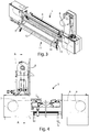
figure 4 is a side view of the assembly illustrated infigure 3 ; -
figure 5 is a sectional view along the A-A section line indicated infigure 4 ; -
figure 6 is an axonometric view showing in detail the auxiliary device for assembling an abrasive belt offigure 3 , in the rest position with the relative gripping member arranged vertically and in the operative position with this gripping member arranged horizontally; -
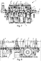
figure 7 is a longitudinal section view of a sanding machine according to a second embodiment of the present invention; and -
figure 8 is a detail view extracted fromfigure 7 . - In the various figures, similar parts will be indicated by the same reference numbers.
- With reference to the attached figures, the
numerical reference 1 indicates a first sanding machine according to the invention, comprising aconveyor belt 2 to allow the advancement of the panels to be machined through saidsanding machine 1 according to the advancing direction A. - The
sanding machine 1 also comprises acontainment cabinet 3, or a covering and protection casing, through which theaforementioned conveyor belt 2 is arranged. - Inside the
containment cabinet 3 and above theconveyor belt 2 there are provided a plurality ofabrasive rollers 4 oriented transversely to said advancing direction A, and also asanding device 5, equipped with anabrasive belt 6, arranged transversely to the same advancing direction A, and wound on adrive pulley 7, driven by amotor 8, and on a drivenpulley 9. - During the operation of the
sanding machine 1, the sanding action exerted by thesanding device 5 on the upper face of each panel passing under it, is performed by the sliding of theabrasive belt 6 on thedrive pulley 7 and on the drivenpulley 9 produced by the rotation of thedrive pulley 7, driven by themotor 8. - Adjacent to the
sanding device 5, and in a position facing the latter, anauxiliary device 11 is provided to facilitate the assembly of theabrasive belt 6 on thedrive pulley 7 and the drivenpulley 9 of thesame sanding device 5 by an operator. - In particular, this
auxiliary device 11 comprises arectilinear guide 12 fixed transversely to the aforementioned advancing direction A, parallel to theabrasive belt 6 of thesanding device 5. - More precisely, both the
abrasive belt 6 of thesanding device 5 and the respective rotation axes of theabrasive rollers 4 and therectilinear guide 12 of theauxiliary device 11 are directed transversely, in particular perpendicularly, to a plane orthogonal to the plane on which they are made to advance the panels to be machined and directed according to the advancing direction A; furthermore, thedrive pulley 7 and the drivenpulley 9 are arranged, respectively, in correspondence with theopposite sides containment cabinet 3. - More specifically, this
rectilinear guide 12 has a length such that the relative ends are, respectively, arranged substantially opposite thedrive pulley 7 and the drivenpulley 9. - The
auxiliary device 11 also includes acarriage 13 movable along therectilinear guide 12 through the use of actuator means. - A
gripping member 14 oscillating vertically between a vertical rest position and a horizontal operating position, is rotatably engaged with the carriage 13 (seefigure 6 ). - Specifically, this gripping
member 14 has an oblong shape, such as to allow, precisely, when arranged in a horizontal position, the gripping of a portion of theabrasive belt 6 by winding the latter to the same grippingmember 14. - When there is the need to replace the
abrasive belt 6, for example, due to the excessive wear of the latter, it is sufficient, after having removed the wornabrasive belt 6, to manually wind a portion of the new belt abrasive on one of the twopulleys member 14, arranged horizontally in a position adjacent to said pulley, and then, after having brought the grippingmember 14 on the opposite side of therectilinear guide 12 by operating the aforesaid actuator means, manually picking up the portion of the abrasive belt from thegripping member 14, and mounting it on the other pulley. - The above operations of replacing the abrasive belt can be easily carried out by a single operator, who, after winding up the new abrasive belt on one of the two
pulleys sanding machine 1 to take the other portion of abrasive belt, carried there by theauxiliary device 11, and wind it on the other of the twopulleys - Clearly, the same operations for replacing the abrasive belt can also be performed jointly by two operators arranged adjacent to the two opposite sides of the
sanding machine 1, in correspondence with the twopulleys - According to a technical variant of the
sanding machine 1, the grippingmember 14 can also be provided fixed in the operative position in the cases in which in thesame sanding machine 1 there are no obstacles to the movement of this grippingmember 14 from one side to the otherrectilinear guide 12. - Referring now to
figures 7 and 8 , there is shows a second sanding machine 1' according to the invention, in which the panels to be machined are interposed between the overlying conveyor belt 2' and a plurality ofsliding rollers 3', 3", idle, underneath the panels, and are made to advance due to the sliding of the conveyor belt 2' according to the advancing direction A'. - Similarly to the
first sanding machine 1 described above, the sanding rollers 4', the sanding belt of the sanding device 5', and the relative auxiliary device of the second sanding machine 1' are oriented transversely to the advancing direction A', according to which the conveyor belt 2' advances the panels to be machined. - Furthermore, the sanding device 5' and the relative auxiliary device of the second sanding machine 1' are substantially identical, respectively, to the
sanding device 5 and theauxiliary device 11 described above in relation to thefirst sanding machine 1. - On the other hand, unlike the
first sanding machine 1, in the second sanding machine 1' the abrasive rollers 4', the sanding device 5' and the relative auxiliary device are provided under the conveyor belt 2', thus allowing the sanding of the lower face of the panels. - In some cases, as in the one shown in
figures 7 and 8 , it may be necessary to lower one or moresliding rollers 3" to create the space necessary for the gripping member 14' of the auxiliary device to arrange itself in the relative horizontal position, and move transversely with respect to the advancing direction A'. - Therefore, said one or more sliding
rollers 3" should be such as to be able to move between a raised position, in which they are interposed between the sanding device 5' and the relative auxiliary device, and a lowered position, in which said one or moresliding rollers 3" are arranged under the sanding device 5' and the relative auxiliary device, and vice versa. - As can be seen from the foregoing description, both the
first sanding machine 1 and the second sanding machine 1' described above allow the abrasive belt of the transversal sanding device to be replaced easily and quickly, avoiding that the belt can become entangled or get stuck in some other members or component of the machine when replacing the abrasive belt. - The present invention has been described for illustrative but not limitative purposes, according to its preferred embodiments, but it is to be understood that modifications and/or changes can be introduced by those skilled in the art without departing from the relevant scope as defined in the enclosed claims.
Claims (9)
- Sanding machine (1, 1') for sanding panels or similar items, comprising:advancing means (2, 2') for advancing, in use, at least one panel or similar item according to a predetermined advancing direction (A, A');at least one sanding device (5, 5') for sanding, in use, at least one panel or similar item during the advancement of said at least one panel or similar item according to said predetermined advancing direction (A, A'), said at least one sanding device (5, 5') comprising a removable abrasive belt (6), directed transversely to said predetermined advancing direction (A, A'); andat least one auxiliary device (11) to promote, in use, fitting of said abrasive belt (6), by an operator, in said at least one sanding device (5, 5'), said at least one auxiliary device (11) comprising movement means (12, 13, 14) for moving, in use, at least one portion of said abrasive belt (6) transversely to said predetermined advancing direction (A, A') from a first position, which is reachable by an operator and adjacent to a first outer edge (10a) of said sanding machine (1, 1'), to a second position reachable by an operator and adjacent to a second outer edge (10b) of said sanding machine (1, 1') opposite said first outer edge (10a).
- Sanding machine (1, 1') according to claim 1, characterized in that in said sanding machine (1, 1') an advancing surface is provided on which said advancing means (2, 2') advances, in use, said at least one panel or similar item according to said advancing direction (A, A'), in that said movement means (12, 13, 14) is configured for moving, in use, said at least one portion of said abrasive belt (6) transversely to a second surface arranged orthogonally to said advancing surface according to said advancing direction (A, A'), and in that said at least one abrasive belt (6)is directed transversely to said second surface.
- Sanding machine (1, 1') according to claim 1 or 2, characterized in that said at least one sanding device (5, 5') comprises a driven pulley (9) and a drive pulley (7) and in that said at least one abrasive belt (6) has a loop shape so as to be windable on said driven pulley (9) and on said drive pulley (7).
- Sanding machine (1, 1') according to any one of the preceding claims, characterized in that said movement means comprises a guide element (12), a movable member (13) movably engaged with said guide element (12), and a gripping element (14, 14') connected to said movable member (13) and configured for gripping, in use, said at least one portion of said abrasive belt (6).
- Sanding machine (1, 1') according to claim 4, characterized in that said gripping element (14, 14') is movable between a substantially vertical position and a substantially horizontal position.
- Sanding machine (1, 1') according to claim 4 or 5, characterized in that said gripping element (14, 14') is rotatable in a vertical direction.
- Sanding machine (1, 1') according to any one of claims 4 to 6, characterized in that said guide element (12) is a substantially rectilinear guide.
- Sanding machine (1, 1') according to any preceding claim, characterized in that said at least one auxiliary device (11) faces said at least one sanding device (5, 5').
- Sanding machine (1') according to claim 2, characterized in that said at least one sanding device (5') and said at least one auxiliary device are arranged below said advancing surface, and in that said sanding machine (1') comprises at least one component (3") that is movable between a raised position, wherein said at least one component (3") is interposed between said at least one sanding device (5') and said at least one auxiliary device, and a lowered position, in which said at least one component (3") is arranged below said at least one sanding device (5') and said at least one auxiliary device.
Applications Claiming Priority (1)
| Application Number | Priority Date | Filing Date | Title |
|---|---|---|---|
| IT102019000023637A IT201900023637A1 (en) | 2019-12-11 | 2019-12-11 | Sanding machine equipped with an auxiliary device to facilitate the assembly of an abrasive belt. |
Publications (2)
| Publication Number | Publication Date |
|---|---|
| EP3834986A1 true EP3834986A1 (en) | 2021-06-16 |
| EP3834986B1 EP3834986B1 (en) | 2024-05-29 |
Family
ID=70154996
Family Applications (1)
| Application Number | Title | Priority Date | Filing Date |
|---|---|---|---|
| EP20210045.9A Active EP3834986B1 (en) | 2019-12-11 | 2020-11-26 | Sanding machine provided with an auxiliary device to facilitate mounting an abrasive belt |
Country Status (2)
| Country | Link |
|---|---|
| EP (1) | EP3834986B1 (en) |
| IT (1) | IT201900023637A1 (en) |
Citations (2)
| Publication number | Priority date | Publication date | Assignee | Title |
|---|---|---|---|---|
| GB1332626A (en) * | 1971-07-22 | 1973-10-03 | Ernst Maschf Gmbh Paul | Belt sander |
| EP0980740A2 (en) * | 1998-08-20 | 2000-02-23 | Benetti Meyers International S.r.l. | Machine for stone surface treatment, particularly for slabs made of stone or similar, such as marbles, granites, but also ceramics and other building materials, used for flooring and lining |
-
2019
- 2019-12-11 IT IT102019000023637A patent/IT201900023637A1/en unknown
-
2020
- 2020-11-26 EP EP20210045.9A patent/EP3834986B1/en active Active
Patent Citations (2)
| Publication number | Priority date | Publication date | Assignee | Title |
|---|---|---|---|---|
| GB1332626A (en) * | 1971-07-22 | 1973-10-03 | Ernst Maschf Gmbh Paul | Belt sander |
| EP0980740A2 (en) * | 1998-08-20 | 2000-02-23 | Benetti Meyers International S.r.l. | Machine for stone surface treatment, particularly for slabs made of stone or similar, such as marbles, granites, but also ceramics and other building materials, used for flooring and lining |
Also Published As
| Publication number | Publication date |
|---|---|
| IT201900023637A1 (en) | 2021-06-11 |
| EP3834986B1 (en) | 2024-05-29 |
Similar Documents
| Publication | Publication Date | Title |
|---|---|---|
| EP1426153B1 (en) | An apparatus for cutting pieces of material into appropriate shaped portions | |
| US3319500A (en) | Apparatus for cutting an elongate web of material into strips | |
| EP3658345B1 (en) | Electronically-controlled apparatus for cutting and machining natural or synthetic stone plates or glass plates | |
| KR101694343B1 (en) | Pipe chamfering apparatus | |
| EP3834986B1 (en) | Sanding machine provided with an auxiliary device to facilitate mounting an abrasive belt | |
| US3340909A (en) | Sawing machine and method | |
| KR200472599Y1 (en) | Heavy board cutting device | |
| US4294047A (en) | Method of sharpening lateral edges and end edges of a blade during reciprocation thereof | |
| EP2241401B1 (en) | Belt sanding machine | |
| CN104471133B (en) | Suction device for the laser link part of working machine such as embroidery machine/sewing machine | |
| KR20100029406A (en) | Stone cutting system | |
| KR20010092896A (en) | A triangular forming cutting automaton for umbrella texture | |
| KR101421193B1 (en) | cutter of roll tape | |
| KR20230152492A (en) | wood cutting apparatus with easy continuous work | |
| EP2123396A1 (en) | Smoothing/brushing machine for wooden articles and relative operating method | |
| US2425944A (en) | Work-started feed mechanism for planers | |
| EP4321296A1 (en) | Improved sanding machine | |
| KR101414837B1 (en) | Automatic Track Cutting Apparatus | |
| CN107385857B (en) | Automatic barrel strip cutting equipment | |
| EP2527108A1 (en) | Edgebanding machine | |
| CN220224706U (en) | Textile fabric cutting device | |
| CN213703632U (en) | Dry abrasive paper die cutting machine convenient to material loading | |
| KR101631582B1 (en) | The device automatically remove the bobbin thread remaining | |
| EP1067200A1 (en) | Machine tool for continuously cutting sheet-like elements, particularly hides and the like | |
| CN209439914U (en) | Gang saw steel strip surface automatically grinding device |
Legal Events
| Date | Code | Title | Description |
|---|---|---|---|
| PUAI | Public reference made under article 153(3) epc to a published international application that has entered the european phase |
Free format text: ORIGINAL CODE: 0009012 |
|
| STAA | Information on the status of an ep patent application or granted ep patent |
Free format text: STATUS: THE APPLICATION HAS BEEN PUBLISHED |
|
| AK | Designated contracting states |
Kind code of ref document: A1 Designated state(s): AL AT BE BG CH CY CZ DE DK EE ES FI FR GB GR HR HU IE IS IT LI LT LU LV MC MK MT NL NO PL PT RO RS SE SI SK SM TR |
|
| STAA | Information on the status of an ep patent application or granted ep patent |
Free format text: STATUS: REQUEST FOR EXAMINATION WAS MADE |
|
| 17P | Request for examination filed |
Effective date: 20211209 |
|
| RBV | Designated contracting states (corrected) |
Designated state(s): AL AT BE BG CH CY CZ DE DK EE ES FI FR GB GR HR HU IE IS IT LI LT LU LV MC MK MT NL NO PL PT RO RS SE SI SK SM TR |
|
| P01 | Opt-out of the competence of the unified patent court (upc) registered |
Effective date: 20230518 |
|
| GRAP | Despatch of communication of intention to grant a patent |
Free format text: ORIGINAL CODE: EPIDOSNIGR1 |
|
| STAA | Information on the status of an ep patent application or granted ep patent |
Free format text: STATUS: GRANT OF PATENT IS INTENDED |
|
| RIC1 | Information provided on ipc code assigned before grant |
Ipc: B24B 21/18 20060101ALI20240108BHEP Ipc: B24B 21/20 20060101ALI20240108BHEP Ipc: B24B 21/04 20060101AFI20240108BHEP |
|
| INTG | Intention to grant announced |
Effective date: 20240129 |
|
| RAP3 | Party data changed (applicant data changed or rights of an application transferred) |
Owner name: SCM GROUP S.P.A. |
|
| GRAS | Grant fee paid |
Free format text: ORIGINAL CODE: EPIDOSNIGR3 |
|
| GRAA | (expected) grant |
Free format text: ORIGINAL CODE: 0009210 |
|
| STAA | Information on the status of an ep patent application or granted ep patent |
Free format text: STATUS: THE PATENT HAS BEEN GRANTED |
|
| AK | Designated contracting states |
Kind code of ref document: B1 Designated state(s): AL AT BE BG CH CY CZ DE DK EE ES FI FR GB GR HR HU IE IS IT LI LT LU LV MC MK MT NL NO PL PT RO RS SE SI SK SM TR |
|
| REG | Reference to a national code |
Ref country code: CH Ref legal event code: EP |
|
| REG | Reference to a national code |
Ref country code: IE Ref legal event code: FG4D |
|
| REG | Reference to a national code |
Ref country code: DE Ref legal event code: R096 Ref document number: 602020031582 Country of ref document: DE |
|
| REG | Reference to a national code |
Ref country code: LT Ref legal event code: MG9D |
|
| REG | Reference to a national code |
Ref country code: NL Ref legal event code: MP Effective date: 20240529 |
|
| PG25 | Lapsed in a contracting state [announced via postgrant information from national office to epo] |
Ref country code: IS Free format text: LAPSE BECAUSE OF FAILURE TO SUBMIT A TRANSLATION OF THE DESCRIPTION OR TO PAY THE FEE WITHIN THE PRESCRIBED TIME-LIMIT Effective date: 20240929 |
|
| PG25 | Lapsed in a contracting state [announced via postgrant information from national office to epo] |
Ref country code: BG Free format text: LAPSE BECAUSE OF FAILURE TO SUBMIT A TRANSLATION OF THE DESCRIPTION OR TO PAY THE FEE WITHIN THE PRESCRIBED TIME-LIMIT Effective date: 20240529 |
|
| PG25 | Lapsed in a contracting state [announced via postgrant information from national office to epo] |
Ref country code: FI Free format text: LAPSE BECAUSE OF FAILURE TO SUBMIT A TRANSLATION OF THE DESCRIPTION OR TO PAY THE FEE WITHIN THE PRESCRIBED TIME-LIMIT Effective date: 20240529 Ref country code: HR Free format text: LAPSE BECAUSE OF FAILURE TO SUBMIT A TRANSLATION OF THE DESCRIPTION OR TO PAY THE FEE WITHIN THE PRESCRIBED TIME-LIMIT Effective date: 20240529 |
|
| PG25 | Lapsed in a contracting state [announced via postgrant information from national office to epo] |
Ref country code: GR Free format text: LAPSE BECAUSE OF FAILURE TO SUBMIT A TRANSLATION OF THE DESCRIPTION OR TO PAY THE FEE WITHIN THE PRESCRIBED TIME-LIMIT Effective date: 20240830 |
|
| REG | Reference to a national code |
Ref country code: AT Ref legal event code: MK05 Ref document number: 1690241 Country of ref document: AT Kind code of ref document: T Effective date: 20240529 |
|
| PG25 | Lapsed in a contracting state [announced via postgrant information from national office to epo] |
Ref country code: ES Free format text: LAPSE BECAUSE OF FAILURE TO SUBMIT A TRANSLATION OF THE DESCRIPTION OR TO PAY THE FEE WITHIN THE PRESCRIBED TIME-LIMIT Effective date: 20240529 |
|
| PG25 | Lapsed in a contracting state [announced via postgrant information from national office to epo] |
Ref country code: AT Free format text: LAPSE BECAUSE OF FAILURE TO SUBMIT A TRANSLATION OF THE DESCRIPTION OR TO PAY THE FEE WITHIN THE PRESCRIBED TIME-LIMIT Effective date: 20240529 |
|
| PG25 | Lapsed in a contracting state [announced via postgrant information from national office to epo] |
Ref country code: PL Free format text: LAPSE BECAUSE OF FAILURE TO SUBMIT A TRANSLATION OF THE DESCRIPTION OR TO PAY THE FEE WITHIN THE PRESCRIBED TIME-LIMIT Effective date: 20240529 |
|
| PG25 | Lapsed in a contracting state [announced via postgrant information from national office to epo] |
Ref country code: LV Free format text: LAPSE BECAUSE OF FAILURE TO SUBMIT A TRANSLATION OF THE DESCRIPTION OR TO PAY THE FEE WITHIN THE PRESCRIBED TIME-LIMIT Effective date: 20240529 |
|
| PG25 | Lapsed in a contracting state [announced via postgrant information from national office to epo] |
Ref country code: PL Free format text: LAPSE BECAUSE OF FAILURE TO SUBMIT A TRANSLATION OF THE DESCRIPTION OR TO PAY THE FEE WITHIN THE PRESCRIBED TIME-LIMIT Effective date: 20240529 Ref country code: NO Free format text: LAPSE BECAUSE OF FAILURE TO SUBMIT A TRANSLATION OF THE DESCRIPTION OR TO PAY THE FEE WITHIN THE PRESCRIBED TIME-LIMIT Effective date: 20240829 Ref country code: LV Free format text: LAPSE BECAUSE OF FAILURE TO SUBMIT A TRANSLATION OF THE DESCRIPTION OR TO PAY THE FEE WITHIN THE PRESCRIBED TIME-LIMIT Effective date: 20240529 Ref country code: IS Free format text: LAPSE BECAUSE OF FAILURE TO SUBMIT A TRANSLATION OF THE DESCRIPTION OR TO PAY THE FEE WITHIN THE PRESCRIBED TIME-LIMIT Effective date: 20240929 Ref country code: HR Free format text: LAPSE BECAUSE OF FAILURE TO SUBMIT A TRANSLATION OF THE DESCRIPTION OR TO PAY THE FEE WITHIN THE PRESCRIBED TIME-LIMIT Effective date: 20240529 Ref country code: GR Free format text: LAPSE BECAUSE OF FAILURE TO SUBMIT A TRANSLATION OF THE DESCRIPTION OR TO PAY THE FEE WITHIN THE PRESCRIBED TIME-LIMIT Effective date: 20240830 Ref country code: FI Free format text: LAPSE BECAUSE OF FAILURE TO SUBMIT A TRANSLATION OF THE DESCRIPTION OR TO PAY THE FEE WITHIN THE PRESCRIBED TIME-LIMIT Effective date: 20240529 Ref country code: ES Free format text: LAPSE BECAUSE OF FAILURE TO SUBMIT A TRANSLATION OF THE DESCRIPTION OR TO PAY THE FEE WITHIN THE PRESCRIBED TIME-LIMIT Effective date: 20240529 Ref country code: BG Free format text: LAPSE BECAUSE OF FAILURE TO SUBMIT A TRANSLATION OF THE DESCRIPTION OR TO PAY THE FEE WITHIN THE PRESCRIBED TIME-LIMIT Effective date: 20240529 Ref country code: AT Free format text: LAPSE BECAUSE OF FAILURE TO SUBMIT A TRANSLATION OF THE DESCRIPTION OR TO PAY THE FEE WITHIN THE PRESCRIBED TIME-LIMIT Effective date: 20240529 Ref country code: RS Free format text: LAPSE BECAUSE OF FAILURE TO SUBMIT A TRANSLATION OF THE DESCRIPTION OR TO PAY THE FEE WITHIN THE PRESCRIBED TIME-LIMIT Effective date: 20240829 |
|
| PG25 | Lapsed in a contracting state [announced via postgrant information from national office to epo] |
Ref country code: NL Free format text: LAPSE BECAUSE OF FAILURE TO SUBMIT A TRANSLATION OF THE DESCRIPTION OR TO PAY THE FEE WITHIN THE PRESCRIBED TIME-LIMIT Effective date: 20240529 |
|
| PG25 | Lapsed in a contracting state [announced via postgrant information from national office to epo] |
Ref country code: NL Free format text: LAPSE BECAUSE OF FAILURE TO SUBMIT A TRANSLATION OF THE DESCRIPTION OR TO PAY THE FEE WITHIN THE PRESCRIBED TIME-LIMIT Effective date: 20240529 |
|
| PG25 | Lapsed in a contracting state [announced via postgrant information from national office to epo] |
Ref country code: DK Free format text: LAPSE BECAUSE OF FAILURE TO SUBMIT A TRANSLATION OF THE DESCRIPTION OR TO PAY THE FEE WITHIN THE PRESCRIBED TIME-LIMIT Effective date: 20240529 |
|
| PG25 | Lapsed in a contracting state [announced via postgrant information from national office to epo] |
Ref country code: EE Free format text: LAPSE BECAUSE OF FAILURE TO SUBMIT A TRANSLATION OF THE DESCRIPTION OR TO PAY THE FEE WITHIN THE PRESCRIBED TIME-LIMIT Effective date: 20240529 |
|
| PG25 | Lapsed in a contracting state [announced via postgrant information from national office to epo] |
Ref country code: CZ Free format text: LAPSE BECAUSE OF FAILURE TO SUBMIT A TRANSLATION OF THE DESCRIPTION OR TO PAY THE FEE WITHIN THE PRESCRIBED TIME-LIMIT Effective date: 20240529 |
|
| PG25 | Lapsed in a contracting state [announced via postgrant information from national office to epo] |
Ref country code: RO Free format text: LAPSE BECAUSE OF FAILURE TO SUBMIT A TRANSLATION OF THE DESCRIPTION OR TO PAY THE FEE WITHIN THE PRESCRIBED TIME-LIMIT Effective date: 20240529 Ref country code: SK Free format text: LAPSE BECAUSE OF FAILURE TO SUBMIT A TRANSLATION OF THE DESCRIPTION OR TO PAY THE FEE WITHIN THE PRESCRIBED TIME-LIMIT Effective date: 20240529 |
|
| PG25 | Lapsed in a contracting state [announced via postgrant information from national office to epo] |
Ref country code: SM Free format text: LAPSE BECAUSE OF FAILURE TO SUBMIT A TRANSLATION OF THE DESCRIPTION OR TO PAY THE FEE WITHIN THE PRESCRIBED TIME-LIMIT Effective date: 20240529 |
|
| PG25 | Lapsed in a contracting state [announced via postgrant information from national office to epo] |
Ref country code: SM Free format text: LAPSE BECAUSE OF FAILURE TO SUBMIT A TRANSLATION OF THE DESCRIPTION OR TO PAY THE FEE WITHIN THE PRESCRIBED TIME-LIMIT Effective date: 20240529 Ref country code: SK Free format text: LAPSE BECAUSE OF FAILURE TO SUBMIT A TRANSLATION OF THE DESCRIPTION OR TO PAY THE FEE WITHIN THE PRESCRIBED TIME-LIMIT Effective date: 20240529 Ref country code: RO Free format text: LAPSE BECAUSE OF FAILURE TO SUBMIT A TRANSLATION OF THE DESCRIPTION OR TO PAY THE FEE WITHIN THE PRESCRIBED TIME-LIMIT Effective date: 20240529 Ref country code: EE Free format text: LAPSE BECAUSE OF FAILURE TO SUBMIT A TRANSLATION OF THE DESCRIPTION OR TO PAY THE FEE WITHIN THE PRESCRIBED TIME-LIMIT Effective date: 20240529 Ref country code: DK Free format text: LAPSE BECAUSE OF FAILURE TO SUBMIT A TRANSLATION OF THE DESCRIPTION OR TO PAY THE FEE WITHIN THE PRESCRIBED TIME-LIMIT Effective date: 20240529 Ref country code: CZ Free format text: LAPSE BECAUSE OF FAILURE TO SUBMIT A TRANSLATION OF THE DESCRIPTION OR TO PAY THE FEE WITHIN THE PRESCRIBED TIME-LIMIT Effective date: 20240529 |
|
| REG | Reference to a national code |
Ref country code: DE Ref legal event code: R097 Ref document number: 602020031582 Country of ref document: DE |
|
| PLBE | No opposition filed within time limit |
Free format text: ORIGINAL CODE: 0009261 |
|
| STAA | Information on the status of an ep patent application or granted ep patent |
Free format text: STATUS: NO OPPOSITION FILED WITHIN TIME LIMIT |
|
| PG25 | Lapsed in a contracting state [announced via postgrant information from national office to epo] |
Ref country code: SI Free format text: LAPSE BECAUSE OF FAILURE TO SUBMIT A TRANSLATION OF THE DESCRIPTION OR TO PAY THE FEE WITHIN THE PRESCRIBED TIME-LIMIT Effective date: 20240529 |
|
| 26N | No opposition filed |
Effective date: 20250303 |
|
| PG25 | Lapsed in a contracting state [announced via postgrant information from national office to epo] |
Ref country code: MC Free format text: LAPSE BECAUSE OF FAILURE TO SUBMIT A TRANSLATION OF THE DESCRIPTION OR TO PAY THE FEE WITHIN THE PRESCRIBED TIME-LIMIT Effective date: 20240529 |
|
| PG25 | Lapsed in a contracting state [announced via postgrant information from national office to epo] |
Ref country code: LU Free format text: LAPSE BECAUSE OF NON-PAYMENT OF DUE FEES Effective date: 20241126 |
|
| GBPC | Gb: european patent ceased through non-payment of renewal fee |
Effective date: 20241126 |
|
| REG | Reference to a national code |
Ref country code: BE Ref legal event code: MM Effective date: 20241130 |
|
| PG25 | Lapsed in a contracting state [announced via postgrant information from national office to epo] |
Ref country code: SE Free format text: LAPSE BECAUSE OF FAILURE TO SUBMIT A TRANSLATION OF THE DESCRIPTION OR TO PAY THE FEE WITHIN THE PRESCRIBED TIME-LIMIT Effective date: 20240529 |
|
| PG25 | Lapsed in a contracting state [announced via postgrant information from national office to epo] |
Ref country code: GB Free format text: LAPSE BECAUSE OF NON-PAYMENT OF DUE FEES Effective date: 20241126 Ref country code: BE Free format text: LAPSE BECAUSE OF NON-PAYMENT OF DUE FEES Effective date: 20241130 |
|
| PG25 | Lapsed in a contracting state [announced via postgrant information from national office to epo] |
Ref country code: FR Free format text: LAPSE BECAUSE OF NON-PAYMENT OF DUE FEES Effective date: 20241130 |
|
| PG25 | Lapsed in a contracting state [announced via postgrant information from national office to epo] |
Ref country code: IE Free format text: LAPSE BECAUSE OF NON-PAYMENT OF DUE FEES Effective date: 20241126 |
|
| REG | Reference to a national code |
Ref country code: CH Ref legal event code: U11 Free format text: ST27 STATUS EVENT CODE: U-0-0-U10-U11 (AS PROVIDED BY THE NATIONAL OFFICE) Effective date: 20251201 |
|
| PGFP | Annual fee paid to national office [announced via postgrant information from national office to epo] |
Ref country code: DE Payment date: 20251118 Year of fee payment: 6 |
|
| PGFP | Annual fee paid to national office [announced via postgrant information from national office to epo] |
Ref country code: IT Payment date: 20251013 Year of fee payment: 6 |
|
| PGFP | Annual fee paid to national office [announced via postgrant information from national office to epo] |
Ref country code: CH Payment date: 20251201 Year of fee payment: 6 |
|
| PG25 | Lapsed in a contracting state [announced via postgrant information from national office to epo] |
Ref country code: PT Free format text: LAPSE BECAUSE OF NON-PAYMENT OF DUE FEES Effective date: 20240529 |
|
| PG25 | Lapsed in a contracting state [announced via postgrant information from national office to epo] |
Ref country code: HU Free format text: LAPSE BECAUSE OF FAILURE TO SUBMIT A TRANSLATION OF THE DESCRIPTION OR TO PAY THE FEE WITHIN THE PRESCRIBED TIME-LIMIT; INVALID AB INITIO Effective date: 20201126 |
|
| PG25 | Lapsed in a contracting state [announced via postgrant information from national office to epo] |
Ref country code: CY Free format text: LAPSE BECAUSE OF FAILURE TO SUBMIT A TRANSLATION OF THE DESCRIPTION OR TO PAY THE FEE WITHIN THE PRESCRIBED TIME-LIMIT; INVALID AB INITIO Effective date: 20201126 |