EP3834895A1 - Skis and snowboards rack - Google Patents
Skis and snowboards rack Download PDFInfo
- Publication number
- EP3834895A1 EP3834895A1 EP20213254.4A EP20213254A EP3834895A1 EP 3834895 A1 EP3834895 A1 EP 3834895A1 EP 20213254 A EP20213254 A EP 20213254A EP 3834895 A1 EP3834895 A1 EP 3834895A1
- Authority
- EP
- European Patent Office
- Prior art keywords
- bars
- clamp unit
- positioning
- post
- snowboards
- Prior art date
- Legal status (The legal status is an assumption and is not a legal conclusion. Google has not performed a legal analysis and makes no representation as to the accuracy of the status listed.)
- Pending
Links
Images


Classifications
-
- A—HUMAN NECESSITIES
- A63—SPORTS; GAMES; AMUSEMENTS
- A63C—SKATES; SKIS; ROLLER SKATES; DESIGN OR LAYOUT OF COURTS, RINKS OR THE LIKE
- A63C11/00—Accessories for skiing or snowboarding
- A63C11/02—Devices for stretching, clamping or pressing skis or snowboards for transportation or storage
- A63C11/028—Storage in cupboards or ski-racks, e.g. with clamping devices
-
- B—PERFORMING OPERATIONS; TRANSPORTING
- B60—VEHICLES IN GENERAL
- B60R—VEHICLES, VEHICLE FITTINGS, OR VEHICLE PARTS, NOT OTHERWISE PROVIDED FOR
- B60R9/00—Supplementary fittings on vehicle exterior for carrying loads, e.g. luggage, sports gear or the like
- B60R9/08—Supplementary fittings on vehicle exterior for carrying loads, e.g. luggage, sports gear or the like specially adapted for sports gear
- B60R9/12—Supplementary fittings on vehicle exterior for carrying loads, e.g. luggage, sports gear or the like specially adapted for sports gear for skis
-
- B—PERFORMING OPERATIONS; TRANSPORTING
- B60—VEHICLES IN GENERAL
- B60R—VEHICLES, VEHICLE FITTINGS, OR VEHICLE PARTS, NOT OTHERWISE PROVIDED FOR
- B60R9/00—Supplementary fittings on vehicle exterior for carrying loads, e.g. luggage, sports gear or the like
- B60R9/06—Supplementary fittings on vehicle exterior for carrying loads, e.g. luggage, sports gear or the like at vehicle front or rear
Definitions
- the present invention relates to a skis and snowboards rack, and more particularly, to a rack connected to rear end of a vehicle for conveniently carrying skis and snowboards.
- the conventional skis and snowboards racks for vehicles are installed to the top of the vehicles and the skis and snowboards are secured on the top of the vehicles.
- the skis and snowboards increase the height of the vehicles and may hit the garage door or parking facility to damage the skiing equipment and the facility.
- the present invention intends to provide a rack for carrying skis and snowboards, and the rack is connected to rear end of a vehicle so as to eliminate shortcomings mentioned above.
- the present invention relates to a skis and snowboards rack, and comprises a post connected to a vehicle, and including a first clamp unit and a second clamp unit respectively connected thereto.
- the first clamp unit includes multiple pairs of first bars, and a first space is formed between each pair of the first bars. Multiple restriction members are slidably mounted to each pair of the first bars.
- the second clamp unit includes multiple pairs of second bars, and a second space is formed between each pair of the second bars. The second spaces are located corresponding to the first spaces.
- An end bar is connected to each of the first clamp unit and the second clamp unit to close up the first spaces and the second spaces.
- the post includes a first positioning section and a second positioning section.
- Each of the first and second positioning section includes multiple holes.
- Multiple first and second positioning members extend through a portion of each of the first and second clamp units and the holes to connect the first and second clamp units to the post.
- one of the two first bars of one pair of the first clamp unit includes a first pivotal end.
- One of the two first bars of another one pair of the first clamp unit includes a first connection end.
- One of the two second bars of one pair of the second clamp unit includes a second pivotal end, and one of the two second bars of another one pair of the second clamp unit includes a second connection end.
- the end bars each have a pivotal portion and an engaging portion, wherein the pivotal portion is pivotably connected to the first/second pivotal end, and the engaging portion is detachably mounted to the first/second connection end.
- the first clamp unit includes two first positioning plates
- the second clamp unit includes two second positioning plates.
- the post is connected between the two first positioning plates and the two second positioning plates.
- the first and second positioning plates of the first and second clamp units are pivotable relative to the post.
- the first clamp unit includes a first tube and two first positioning plates which are connected to the first tube.
- Each first positioning plate includes first bores defined through at least three corners thereof.
- the multiple pairs of first bars are connected to the first tube.
- the first positioning plates are pivotably connected to the first positioning section of the post by multiple first positioning members.
- the first positioning plates are pivotable about one of the first positioning members at one of corners thereof.
- the second clamp unit includes a second tube and two second positioning plates which are connected to the second tube.
- Each second positioning plate includes second bores defined through at least three corners thereof.
- the multiple pairs of second bars are connected to the second tube.
- the second positioning plates are pivotably connected to the second positioning section of the post by multiple second positioning members.
- the second positioning plates are pivotable about one of the second positioning member at one of corners thereof.
- the primary object of the present invention is to provide a skis and snowboards rack that is connected to the rear end of a vehicle so as not to increase the height of the vehicle and not to block the driver's sight.
- Another object of the present invention is that the skis and snowboards are positioned in the first and second spaces between the first and second bars.
- the restriction members further position the skis and snowboards.
- Yet another object of the present invention is that the skis and snowboards rack can also be used to secure surfing boards.
- the skis and snowboards rack of the present invention comprises a post 1 which is connected to rear end of a vehicle (not shown).
- a first clamp unit 2 is connected to the upper portion of the post 1, and a second clamp unit 3 is connected to the lower portion of the post 1.
- the first clamp unit 2 includes two pairs of first bars 21.
- a first space 22 is formed between each pair of the first bars 21.
- Multiple restriction members 23 are slidably mounted to each pair of the first bars 21.
- the restriction members 23 are slidable along the first bars 21 to adjust the distance between the restriction members 23.
- the first bars 21 are mounted with sleeves made of soft or resilient material.
- the second clamp unit 3 includes two pairs of second bars 31.
- a second space 32 is formed between each pair of the second bars 31.
- the second spaces 32 are located corresponding to the first spaces 22.
- the second bars 31 are mounted with sleeves made of soft or resilient material.
- the post 1 includes a first positioning section 11 and a second positioning section 12.
- Each of the first and second positioning section 11, 12 includes multiple holes 111/121.
- the first clamp unit 2 includes a first tube 24 and two first positioning plates 25 which are connected to the first tube 24.
- Each first positioning plate 25 includes first bores 251 defined through three corners thereof.
- the multiple pairs of first bars 21 are connected to the first tube 24.
- the first positioning plates 25 are pivotably connected to the first positioning section 11 of the post 1 by multiple first positioning members 5 which extend through the first bores 251 and the holes 111 so as to connect the first clamp unit 2 to the post 1.
- the second clamp unit 3 includes a second tube 34 and two second positioning plates 35 which are connected to the second tube 34.
- Each second positioning plate 35 includes second bores 351 defined through three corners thereof.
- the multiple pairs of second bars 31 are connected to the second tube 34.
- the second positioning plates 35 are pivotably connected to the second positioning section 12 of the post 1 by multiple second positioning members 50 extending through the second bores 351 and the holes 121 so as to connect the second clamp unit 3 to the post 1.
- An end bar 4 is connected to each of the first clamp unit 2 and the second clamp unit 3 to close up the first spaces 22 and the second spaces 32.
- one of the two first bars 21 of one pair of the first clamp unit 2 includes a first pivotal end 211
- one of the two first bars 21 of another one pair of the first clamp unit 2 includes a first connection end 212 as shown in Fig. 2 .
- the end bars 4 each have a pivotal portion 41 and an engaging portion 42, wherein the pivotal portion 41 is pivotably connected to the first pivotal end 211, and the engaging portion 42 is detachably mounted to the first connection end 212.
- one of the two second bars 31 of one pair of the second clamp unit 3 includes a second pivotal end 311.
- One of the two second bars 31 of another one pair of the second clamp unit 3 includes a second connection end 312.
- the pivotal portion 41 of the end bar 4 corresponding to the second clamp unit 3 is pivotably connected to the second pivotal end 311, and the engaging portion 42 of the end bar 4 corresponding to the second clamp unit 3 is detachably mounted to the second connection end 312.
- each of the two respective end bars 4 is pivoted about the pivotal portion 41, and the engaging portion 42 of the end bar 4 is separated from the first/second connection ends 212/312 so as to form an entrance 221/321 as shown in Fig. 4 .
- the restriction members 23 are released and moved to proper positions, so that the snowboard can be inserted into the first and second spaces 22, 32.
- the restriction members 23 contact two sides of the snowboard, and are secured to the first bar 21 as shown in Fig. 5 .
- the end bars 4 are then pivoted to engage the engaging portions 42 with the first and second connection ends 22, 312 of the first and second bars 21, 31 to close the entrances 221, 321.
- the first and second clamp units 2, 3 can be moved along the first and second positioning sections 11, 12 of the post 1 by removing the first and second positioning members 5, 50 out from the first and second bores 251, 351 of the first and second positioning plates 25, 35 of the first and second clamp units 2, 3, and the holes 111, 121.
- the first and second clamp units 2, 3 are able to position the snowboards of different lengths.
- the first and second positioning members 5, 50 are removed from the first and second bores 251, 351 of one of the corners, and the first and second positioning plates 25, 35 are connected to the post 1 by only one corner. Therefore, the first and second clamp units 2, 3 are pivotable relative to the post 1 about the first and second positioning members 5, 50 at the corners of the first and second positioning plates 25, 35. The first and second clamp units 2, 3 are pivoted to be parallel to the post 1. The first and second positioning members 5, 50 are again extended through the first and second bores 251, 351 of another corners of the first and second first positioning plates 25, 35 and the holes 111, 121 to position the first and second clamp units 2, 3. The folded status of the rack saves space.
Abstract
Description
- The present invention relates to a skis and snowboards rack, and more particularly, to a rack connected to rear end of a vehicle for conveniently carrying skis and snowboards.
- The conventional skis and snowboards racks for vehicles are installed to the top of the vehicles and the skis and snowboards are secured on the top of the vehicles. However, the skis and snowboards increase the height of the vehicles and may hit the garage door or parking facility to damage the skiing equipment and the facility.
- The present invention intends to provide a rack for carrying skis and snowboards, and the rack is connected to rear end of a vehicle so as to eliminate shortcomings mentioned above.
- The present invention relates to a skis and snowboards rack, and comprises a post connected to a vehicle, and including a first clamp unit and a second clamp unit respectively connected thereto. The first clamp unit includes multiple pairs of first bars, and a first space is formed between each pair of the first bars. Multiple restriction members are slidably mounted to each pair of the first bars. The second clamp unit includes multiple pairs of second bars, and a second space is formed between each pair of the second bars. The second spaces are located corresponding to the first spaces. An end bar is connected to each of the first clamp unit and the second clamp unit to close up the first spaces and the second spaces.
- Preferably, the post includes a first positioning section and a second positioning section. Each of the first and second positioning section includes multiple holes. Multiple first and second positioning members extend through a portion of each of the first and second clamp units and the holes to connect the first and second clamp units to the post.
- Preferably, one of the two first bars of one pair of the first clamp unit includes a first pivotal end. One of the two first bars of another one pair of the first clamp unit includes a first connection end. One of the two second bars of one pair of the second clamp unit includes a second pivotal end, and one of the two second bars of another one pair of the second clamp unit includes a second connection end. The end bars each have a pivotal portion and an engaging portion, wherein the pivotal portion is pivotably connected to the first/second pivotal end, and the engaging portion is detachably mounted to the first/second connection end.
- Preferably, the first clamp unit includes two first positioning plates, and the second clamp unit includes two second positioning plates. The post is connected between the two first positioning plates and the two second positioning plates. The first and second positioning plates of the first and second clamp units are pivotable relative to the post.
- Preferably, the first clamp unit includes a first tube and two first positioning plates which are connected to the first tube. Each first positioning plate includes first bores defined through at least three corners thereof. The multiple pairs of first bars are connected to the first tube. The first positioning plates are pivotably connected to the first positioning section of the post by multiple first positioning members. The first positioning plates are pivotable about one of the first positioning members at one of corners thereof.
- Preferably, the second clamp unit includes a second tube and two second positioning plates which are connected to the second tube. Each second positioning plate includes second bores defined through at least three corners thereof. The multiple pairs of second bars are connected to the second tube. The second positioning plates are pivotably connected to the second positioning section of the post by multiple second positioning members. The second positioning plates are pivotable about one of the second positioning member at one of corners thereof.
- The primary object of the present invention is to provide a skis and snowboards rack that is connected to the rear end of a vehicle so as not to increase the height of the vehicle and not to block the driver's sight.
- Another object of the present invention is that the skis and snowboards are positioned in the first and second spaces between the first and second bars. The restriction members further position the skis and snowboards.
- Yet another object of the present invention is that the skis and snowboards rack can also be used to secure surfing boards.
- The present invention will become more obvious from the following description when taken in connection with the accompanying drawings which show, for purposes of illustration only, a preferred embodiment in accordance with the present invention.
-
-
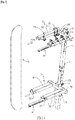
Fig. 1 is a perspective view to show the skis and snowboards rack of the present invention; -
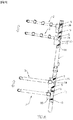
Fig. 2 is an exploded view of the skis and snowboards rack of the present invention; -
Fig. 3 shows that the end bars are pivoted relative to the first and second clamp units of the skis and snowboards rack of the present invention; -
Fig. 4 shows that a snowboard is to be positioned to skis and snowboards rack of the present invention; -
Fig. 5 shows that a snowboard is positioned to skis and snowboards rack of the present invention; -
Figs. 6 and7 show that the first and second clamp units are adjusted along the post; -
Fig. 8 shows that the first and second clamp units are pivoted relative to the post, and -
Fig. 9 shows that the first and second clamp units are folded to be parallel to the post. - Referring to
Figs. 1 to 5 , the skis and snowboards rack of the present invention comprises apost 1 which is connected to rear end of a vehicle (not shown). Afirst clamp unit 2 is connected to the upper portion of thepost 1, and asecond clamp unit 3 is connected to the lower portion of thepost 1. Thefirst clamp unit 2 includes two pairs offirst bars 21. Afirst space 22 is formed between each pair of thefirst bars 21.Multiple restriction members 23 are slidably mounted to each pair of thefirst bars 21. Therestriction members 23 are slidable along thefirst bars 21 to adjust the distance between therestriction members 23. Thefirst bars 21 are mounted with sleeves made of soft or resilient material. - The
second clamp unit 3 includes two pairs ofsecond bars 31. Asecond space 32 is formed between each pair of thesecond bars 31. Thesecond spaces 32 are located corresponding to thefirst spaces 22. Thesecond bars 31 are mounted with sleeves made of soft or resilient material. - The
post 1 includes afirst positioning section 11 and asecond positioning section 12. Each of the first andsecond positioning section multiple holes 111/121. - Specifically, the
first clamp unit 2 includes afirst tube 24 and twofirst positioning plates 25 which are connected to thefirst tube 24. Eachfirst positioning plate 25 includesfirst bores 251 defined through three corners thereof. The multiple pairs offirst bars 21 are connected to thefirst tube 24. Thefirst positioning plates 25 are pivotably connected to thefirst positioning section 11 of thepost 1 by multiplefirst positioning members 5 which extend through thefirst bores 251 and theholes 111 so as to connect thefirst clamp unit 2 to thepost 1. Similarly, thesecond clamp unit 3 includes asecond tube 34 and twosecond positioning plates 35 which are connected to thesecond tube 34. Eachsecond positioning plate 35 includessecond bores 351 defined through three corners thereof. The multiple pairs ofsecond bars 31 are connected to thesecond tube 34. Thesecond positioning plates 35 are pivotably connected to thesecond positioning section 12 of thepost 1 by multiplesecond positioning members 50 extending through thesecond bores 351 and theholes 121 so as to connect thesecond clamp unit 3 to thepost 1. - An
end bar 4 is connected to each of thefirst clamp unit 2 and thesecond clamp unit 3 to close up thefirst spaces 22 and thesecond spaces 32. Specifically, one of the twofirst bars 21 of one pair of thefirst clamp unit 2 includes a firstpivotal end 211, one of the twofirst bars 21 of another one pair of thefirst clamp unit 2 includes afirst connection end 212 as shown inFig. 2 . The end bars 4 each have apivotal portion 41 and an engagingportion 42, wherein thepivotal portion 41 is pivotably connected to the firstpivotal end 211, and the engagingportion 42 is detachably mounted to thefirst connection end 212. Similarly, one of the twosecond bars 31 of one pair of thesecond clamp unit 3 includes a secondpivotal end 311. One of the twosecond bars 31 of another one pair of thesecond clamp unit 3 includes asecond connection end 312. Thepivotal portion 41 of theend bar 4 corresponding to thesecond clamp unit 3 is pivotably connected to the secondpivotal end 311, and the engagingportion 42 of theend bar 4 corresponding to thesecond clamp unit 3 is detachably mounted to thesecond connection end 312. - When in use, as shown in
Figs. 3 and4 , each of the tworespective end bars 4 is pivoted about thepivotal portion 41, and the engagingportion 42 of theend bar 4 is separated from the first/second connection ends 212/312 so as to form anentrance 221/321 as shown inFig. 4 . Therestriction members 23 are released and moved to proper positions, so that the snowboard can be inserted into the first andsecond spaces restriction members 23 contact two sides of the snowboard, and are secured to thefirst bar 21 as shown inFig. 5 . The end bars 4 are then pivoted to engage the engagingportions 42 with the first and second connection ends 22, 312 of the first andsecond bars entrances - As shown in
Figs. 6 and7 , the first andsecond clamp units second positioning sections post 1 by removing the first andsecond positioning members second bores second positioning plates second clamp units holes second clamp units - As shown in
Figs. 8 and9 , when the rack is not in use, the first andsecond positioning members second bores second positioning plates post 1 by only one corner. Therefore, the first andsecond clamp units post 1 about the first andsecond positioning members second positioning plates second clamp units post 1. The first andsecond positioning members second bores first positioning plates holes second clamp units - While we have shown and described the embodiment in accordance with the present invention, it should be clear to those skilled in the art that further embodiments may be made without departing from the scope of the present invention.
Claims (6)
- A skis and snowboards rack comprising:a post adapted to be connected to a vehicle, a first clamp unit and a second clamp unit respectively connected to the post;the first clamp unit including multiple pairs of first bars, a first space formed between each pair of the first bars, multiple restriction members slidably mounted to each pair of the first bars;the second clamp unit including multiple pairs of second bars, a second space formed between each pair of the second bars, the second spaces located corresponding to the first spaces, andan end bar connected to each of the first clamp unit and the second clamp unit to close up the first spaces and the second spaces.
- The skis and snowboards rack as claimed in claim 1, wherein the post includes a first positioning section and a second positioning section, each of the first and second positioning section includes multiple holes, multiple first and second positioning members extend through a portion of each of the first and second clamp units and the holes to connect the first and second clamp units to the post.
- The skis and snowboards rack as claimed in claim 1, wherein one of the two first bars of one pair of the first clamp unit includes a first pivotal end, one of the two first bars of another one pair of the first clamp unit includes a first connection end;one of the two second bars of one pair of the second clamp unit includes a second pivotal end, one of the two second bars of another one pair of the second clamp unit includes a second connection end;the end bars each have a pivotal portion and an engaging portion, the pivotal portion is pivotably connected to the first/second pivotal end, the engaging portion is detachably mounted to the first/second connection end.
- The skis and snowboards rack as claimed in claim 1, wherein the first clamp unit includes two first positioning plates, the second clamp unit includes two second positioning plates, the post is connected between the two first positioning plates and the two second positioning plates, the first and second positioning plates of the first and second clamp units) are pivotable relative to the post.
- The skis and snowboards rack as claimed in claim 2, wherein the first clamp unit includes a first tube and two first positioning plates which are connected to the first tube, each first positioning plate includes first bores defined through at least three corners thereof, the multiple pairs of first bars are connected to the first tube, the first positioning plates are pivotably connected to the first positioning section of the post by multiple first positioning members, the first positioning plates are pivotable about one of the first positioning members at one of corners thereof.
- The skis and snowboards rack as claimed in claim 2, wherein the second clamp unit includes a second tube and two second positioning plates which are connected to the second tube, each second positioning plate includes second bores defined through at least three corners thereof, the multiple pairs of second bars are connected to the second tube, the second positioning plates are pivotably connected to the second positioning section of the post by multiple second positioning members, the second positioning plates are pivotable about one of the second positioning member at one of corners thereof.
Applications Claiming Priority (1)
| Application Number | Priority Date | Filing Date | Title |
|---|---|---|---|
| TW108216555U TWM593279U (en) | 2019-12-13 | 2019-12-13 | Clamping seat structure on sled carrying frame |
Publications (1)
| Publication Number | Publication Date |
|---|---|
| EP3834895A1 true EP3834895A1 (en) | 2021-06-16 |
Family
ID=71133534
Family Applications (1)
| Application Number | Title | Priority Date | Filing Date |
|---|---|---|---|
| EP20213254.4A Pending EP3834895A1 (en) | 2019-12-13 | 2020-12-10 | Skis and snowboards rack |
Country Status (3)
| Country | Link |
|---|---|
| US (1) | US20210178980A1 (en) |
| EP (1) | EP3834895A1 (en) |
| TW (1) | TWM593279U (en) |
Families Citing this family (3)
| Publication number | Priority date | Publication date | Assignee | Title |
|---|---|---|---|---|
| TWI761262B (en) * | 2021-07-14 | 2022-04-11 | 薩摩亞國商佑達創新有限公司 | Snowboard fixing frame |
| US11491921B1 (en) * | 2021-07-21 | 2022-11-08 | Yotta Innovation Co., Ltd. | Snowboard fixing frame |
| US20230294615A1 (en) * | 2022-03-20 | 2023-09-21 | Gregg Allen Wicken | Collapsible Side Mounting Equipment Rack |
Citations (4)
| Publication number | Priority date | Publication date | Assignee | Title |
|---|---|---|---|---|
| US5181822A (en) * | 1989-08-23 | 1993-01-26 | Allsop, Inc. | Articulated support rack for vehicles |
| US5449100A (en) * | 1993-08-02 | 1995-09-12 | Eckhart; Richard A. | Carrier for skis and ski poles |
| US20050205630A1 (en) * | 2004-03-16 | 2005-09-22 | David Cooper | Surf and ski transport |
| US9656611B1 (en) * | 2016-08-04 | 2017-05-23 | Gadi Beer | Transportable ski rack |
-
2019
- 2019-12-13 TW TW108216555U patent/TWM593279U/en unknown
-
2020
- 2020-09-30 US US17/039,583 patent/US20210178980A1/en not_active Abandoned
- 2020-12-10 EP EP20213254.4A patent/EP3834895A1/en active Pending
Patent Citations (4)
| Publication number | Priority date | Publication date | Assignee | Title |
|---|---|---|---|---|
| US5181822A (en) * | 1989-08-23 | 1993-01-26 | Allsop, Inc. | Articulated support rack for vehicles |
| US5449100A (en) * | 1993-08-02 | 1995-09-12 | Eckhart; Richard A. | Carrier for skis and ski poles |
| US20050205630A1 (en) * | 2004-03-16 | 2005-09-22 | David Cooper | Surf and ski transport |
| US9656611B1 (en) * | 2016-08-04 | 2017-05-23 | Gadi Beer | Transportable ski rack |
Also Published As
| Publication number | Publication date |
|---|---|
| US20210178980A1 (en) | 2021-06-17 |
| TWM593279U (en) | 2020-04-11 |
Similar Documents
| Publication | Publication Date | Title |
|---|---|---|
| EP3834895A1 (en) | Skis and snowboards rack | |
| US9668372B2 (en) | Cable management device | |
| US20180098626A1 (en) | Bracket device | |
| US9861193B2 (en) | Bracket device | |
| US6554171B1 (en) | Golf bag rack attachable to vehicle hitch | |
| US9867308B2 (en) | Slide rail assembly | |
| US6712226B1 (en) | Wall or ceiling mountable brackets for storing and displaying board-based recreational equipment | |
| US20160262538A1 (en) | Slide rail assembly | |
| US6196397B1 (en) | Rack for holding a gliding board | |
| US20080230579A1 (en) | Bicycle rack with wheel securing devices | |
| US10709033B2 (en) | Coupling assembly and cable management device thereof | |
| EP1280363A3 (en) | Angled patch panel with cable support bar for network cable racks | |
| US10827642B2 (en) | Rack system and cable supporting assembly thereof | |
| US11439036B2 (en) | Slide rail assembly | |
| EP3258755B1 (en) | Rack system | |
| US6824157B1 (en) | Telescoping tower hitch assembly | |
| RU2001125897A (en) | Folding ski | |
| US20140021154A1 (en) | Movable lugs and assistance device for removing equipment from rack | |
| US6510953B2 (en) | Rack for removably holding rods | |
| CA2690024A1 (en) | Dynamic hinge for ladder | |
| US5108020A (en) | Apparatus for carrying skis | |
| EP2672795B1 (en) | Movable lugs and assistance device for removing equipment from rack | |
| US2865513A (en) | Plate glass storage rack | |
| US20030201290A1 (en) | Angled ski rack attachment for a sports rack | |
| JPH07508450A (en) | Device for holding shoes on gliding boards |
Legal Events
| Date | Code | Title | Description |
|---|---|---|---|
| PUAI | Public reference made under article 153(3) epc to a published international application that has entered the european phase |
Free format text: ORIGINAL CODE: 0009012 |
|
| STAA | Information on the status of an ep patent application or granted ep patent |
Free format text: STATUS: THE APPLICATION HAS BEEN PUBLISHED |
|
| AK | Designated contracting states |
Kind code of ref document: A1 Designated state(s): AL AT BE BG CH CY CZ DE DK EE ES FI FR GB GR HR HU IE IS IT LI LT LU LV MC MK MT NL NO PL PT RO RS SE SI SK SM TR |
|
| STAA | Information on the status of an ep patent application or granted ep patent |
Free format text: STATUS: REQUEST FOR EXAMINATION WAS MADE |
|
| 17P | Request for examination filed |
Effective date: 20211216 |
|
| RBV | Designated contracting states (corrected) |
Designated state(s): AL AT BE BG CH CY CZ DE DK EE ES FI FR GB GR HR HU IE IS IT LI LT LU LV MC MK MT NL NO PL PT RO RS SE SI SK SM TR |