EP3834871B1 - Computerprogramm zur erkennung des ventilatorauslösers, vorrichtung zur erkennung des ventilatorauslösers und ventilator - Google Patents
Computerprogramm zur erkennung des ventilatorauslösers, vorrichtung zur erkennung des ventilatorauslösers und ventilator Download PDFInfo
- Publication number
- EP3834871B1 EP3834871B1 EP18931204.4A EP18931204A EP3834871B1 EP 3834871 B1 EP3834871 B1 EP 3834871B1 EP 18931204 A EP18931204 A EP 18931204A EP 3834871 B1 EP3834871 B1 EP 3834871B1
- Authority
- EP
- European Patent Office
- Prior art keywords
- ventilation
- trigger
- ventilator
- patient
- inspiratory
- Prior art date
- Legal status (The legal status is an assumption and is not a legal conclusion. Google has not performed a legal analysis and makes no representation as to the accuracy of the status listed.)
- Active
Links
Images




Classifications
-
- A—HUMAN NECESSITIES
- A61—MEDICAL OR VETERINARY SCIENCE; HYGIENE
- A61M—DEVICES FOR INTRODUCING MEDIA INTO, OR ONTO, THE BODY; DEVICES FOR TRANSDUCING BODY MEDIA OR FOR TAKING MEDIA FROM THE BODY; DEVICES FOR PRODUCING OR ENDING SLEEP OR STUPOR
- A61M16/00—Devices for influencing the respiratory system of patients by gas treatment, e.g. ventilators; Tracheal tubes
- A61M16/021—Devices for influencing the respiratory system of patients by gas treatment, e.g. ventilators; Tracheal tubes operated by electrical means
- A61M16/022—Control means therefor
- A61M16/024—Control means therefor including calculation means, e.g. using a processor
-
- A—HUMAN NECESSITIES
- A61—MEDICAL OR VETERINARY SCIENCE; HYGIENE
- A61B—DIAGNOSIS; SURGERY; IDENTIFICATION
- A61B5/00—Measuring for diagnostic purposes; Identification of persons
- A61B5/08—Measuring devices for evaluating the respiratory organs
- A61B5/087—Measuring breath flow
-
- A—HUMAN NECESSITIES
- A61—MEDICAL OR VETERINARY SCIENCE; HYGIENE
- A61B—DIAGNOSIS; SURGERY; IDENTIFICATION
- A61B5/00—Measuring for diagnostic purposes; Identification of persons
- A61B5/72—Signal processing specially adapted for physiological signals or for diagnostic purposes
- A61B5/7271—Specific aspects of physiological measurement analysis
- A61B5/7275—Determining trends in physiological measurement data; Predicting development of a medical condition based on physiological measurements, e.g. determining a risk factor
-
- G—PHYSICS
- G16—INFORMATION AND COMMUNICATION TECHNOLOGY [ICT] SPECIALLY ADAPTED FOR SPECIFIC APPLICATION FIELDS
- G16H—HEALTHCARE INFORMATICS, i.e. INFORMATION AND COMMUNICATION TECHNOLOGY [ICT] SPECIALLY ADAPTED FOR THE HANDLING OR PROCESSING OF MEDICAL OR HEALTHCARE DATA
- G16H20/00—ICT specially adapted for therapies or health-improving plans, e.g. for handling prescriptions, for steering therapy or for monitoring patient compliance
- G16H20/40—ICT specially adapted for therapies or health-improving plans, e.g. for handling prescriptions, for steering therapy or for monitoring patient compliance relating to mechanical, radiation or invasive therapies, e.g. surgery, laser therapy, dialysis or acupuncture
-
- G—PHYSICS
- G16—INFORMATION AND COMMUNICATION TECHNOLOGY [ICT] SPECIALLY ADAPTED FOR SPECIFIC APPLICATION FIELDS
- G16H—HEALTHCARE INFORMATICS, i.e. INFORMATION AND COMMUNICATION TECHNOLOGY [ICT] SPECIALLY ADAPTED FOR THE HANDLING OR PROCESSING OF MEDICAL OR HEALTHCARE DATA
- G16H40/00—ICT specially adapted for the management or administration of healthcare resources or facilities; ICT specially adapted for the management or operation of medical equipment or devices
- G16H40/60—ICT specially adapted for the management or administration of healthcare resources or facilities; ICT specially adapted for the management or operation of medical equipment or devices for the operation of medical equipment or devices
- G16H40/67—ICT specially adapted for the management or administration of healthcare resources or facilities; ICT specially adapted for the management or operation of medical equipment or devices for the operation of medical equipment or devices for remote operation
-
- G—PHYSICS
- G16—INFORMATION AND COMMUNICATION TECHNOLOGY [ICT] SPECIALLY ADAPTED FOR SPECIFIC APPLICATION FIELDS
- G16H—HEALTHCARE INFORMATICS, i.e. INFORMATION AND COMMUNICATION TECHNOLOGY [ICT] SPECIALLY ADAPTED FOR THE HANDLING OR PROCESSING OF MEDICAL OR HEALTHCARE DATA
- G16H50/00—ICT specially adapted for medical diagnosis, medical simulation or medical data mining; ICT specially adapted for detecting, monitoring or modelling epidemics or pandemics
- G16H50/20—ICT specially adapted for medical diagnosis, medical simulation or medical data mining; ICT specially adapted for detecting, monitoring or modelling epidemics or pandemics for computer-aided diagnosis, e.g. based on medical expert systems
-
- A—HUMAN NECESSITIES
- A61—MEDICAL OR VETERINARY SCIENCE; HYGIENE
- A61B—DIAGNOSIS; SURGERY; IDENTIFICATION
- A61B5/00—Measuring for diagnostic purposes; Identification of persons
- A61B5/08—Measuring devices for evaluating the respiratory organs
- A61B5/087—Measuring breath flow
- A61B5/0871—Peak expiratory flowmeters
-
- A—HUMAN NECESSITIES
- A61—MEDICAL OR VETERINARY SCIENCE; HYGIENE
- A61M—DEVICES FOR INTRODUCING MEDIA INTO, OR ONTO, THE BODY; DEVICES FOR TRANSDUCING BODY MEDIA OR FOR TAKING MEDIA FROM THE BODY; DEVICES FOR PRODUCING OR ENDING SLEEP OR STUPOR
- A61M16/00—Devices for influencing the respiratory system of patients by gas treatment, e.g. ventilators; Tracheal tubes
- A61M16/0051—Devices for influencing the respiratory system of patients by gas treatment, e.g. ventilators; Tracheal tubes with alarm devices
-
- A—HUMAN NECESSITIES
- A61—MEDICAL OR VETERINARY SCIENCE; HYGIENE
- A61M—DEVICES FOR INTRODUCING MEDIA INTO, OR ONTO, THE BODY; DEVICES FOR TRANSDUCING BODY MEDIA OR FOR TAKING MEDIA FROM THE BODY; DEVICES FOR PRODUCING OR ENDING SLEEP OR STUPOR
- A61M16/00—Devices for influencing the respiratory system of patients by gas treatment, e.g. ventilators; Tracheal tubes
- A61M16/0003—Accessories therefor, e.g. sensors, vibrators, negative pressure
- A61M2016/0027—Accessories therefor, e.g. sensors, vibrators, negative pressure pressure meter
-
- A—HUMAN NECESSITIES
- A61—MEDICAL OR VETERINARY SCIENCE; HYGIENE
- A61M—DEVICES FOR INTRODUCING MEDIA INTO, OR ONTO, THE BODY; DEVICES FOR TRANSDUCING BODY MEDIA OR FOR TAKING MEDIA FROM THE BODY; DEVICES FOR PRODUCING OR ENDING SLEEP OR STUPOR
- A61M16/00—Devices for influencing the respiratory system of patients by gas treatment, e.g. ventilators; Tracheal tubes
- A61M16/0003—Accessories therefor, e.g. sensors, vibrators, negative pressure
- A61M2016/003—Accessories therefor, e.g. sensors, vibrators, negative pressure with a flowmeter
- A61M2016/0033—Accessories therefor, e.g. sensors, vibrators, negative pressure with a flowmeter electrical
-
- A—HUMAN NECESSITIES
- A61—MEDICAL OR VETERINARY SCIENCE; HYGIENE
- A61M—DEVICES FOR INTRODUCING MEDIA INTO, OR ONTO, THE BODY; DEVICES FOR TRANSDUCING BODY MEDIA OR FOR TAKING MEDIA FROM THE BODY; DEVICES FOR PRODUCING OR ENDING SLEEP OR STUPOR
- A61M2205/00—General characteristics of the apparatus
- A61M2205/33—Controlling, regulating or measuring
- A61M2205/3331—Pressure; Flow
-
- A—HUMAN NECESSITIES
- A61—MEDICAL OR VETERINARY SCIENCE; HYGIENE
- A61M—DEVICES FOR INTRODUCING MEDIA INTO, OR ONTO, THE BODY; DEVICES FOR TRANSDUCING BODY MEDIA OR FOR TAKING MEDIA FROM THE BODY; DEVICES FOR PRODUCING OR ENDING SLEEP OR STUPOR
- A61M2205/00—General characteristics of the apparatus
- A61M2205/50—General characteristics of the apparatus with microprocessors or computers
- A61M2205/502—User interfaces, e.g. screens or keyboards
-
- A—HUMAN NECESSITIES
- A61—MEDICAL OR VETERINARY SCIENCE; HYGIENE
- A61M—DEVICES FOR INTRODUCING MEDIA INTO, OR ONTO, THE BODY; DEVICES FOR TRANSDUCING BODY MEDIA OR FOR TAKING MEDIA FROM THE BODY; DEVICES FOR PRODUCING OR ENDING SLEEP OR STUPOR
- A61M2205/00—General characteristics of the apparatus
- A61M2205/50—General characteristics of the apparatus with microprocessors or computers
- A61M2205/502—User interfaces, e.g. screens or keyboards
- A61M2205/505—Touch-screens; Virtual keyboard or keypads; Virtual buttons; Soft keys; Mouse touches
-
- A—HUMAN NECESSITIES
- A61—MEDICAL OR VETERINARY SCIENCE; HYGIENE
- A61M—DEVICES FOR INTRODUCING MEDIA INTO, OR ONTO, THE BODY; DEVICES FOR TRANSDUCING BODY MEDIA OR FOR TAKING MEDIA FROM THE BODY; DEVICES FOR PRODUCING OR ENDING SLEEP OR STUPOR
- A61M2205/00—General characteristics of the apparatus
- A61M2205/50—General characteristics of the apparatus with microprocessors or computers
- A61M2205/52—General characteristics of the apparatus with microprocessors or computers with memories providing a history of measured variating parameters of apparatus or patient
-
- A—HUMAN NECESSITIES
- A61—MEDICAL OR VETERINARY SCIENCE; HYGIENE
- A61M—DEVICES FOR INTRODUCING MEDIA INTO, OR ONTO, THE BODY; DEVICES FOR TRANSDUCING BODY MEDIA OR FOR TAKING MEDIA FROM THE BODY; DEVICES FOR PRODUCING OR ENDING SLEEP OR STUPOR
- A61M2205/00—General characteristics of the apparatus
- A61M2205/58—Means for facilitating use, e.g. by people with impaired vision
- A61M2205/581—Means for facilitating use, e.g. by people with impaired vision by audible feedback
-
- A—HUMAN NECESSITIES
- A61—MEDICAL OR VETERINARY SCIENCE; HYGIENE
- A61M—DEVICES FOR INTRODUCING MEDIA INTO, OR ONTO, THE BODY; DEVICES FOR TRANSDUCING BODY MEDIA OR FOR TAKING MEDIA FROM THE BODY; DEVICES FOR PRODUCING OR ENDING SLEEP OR STUPOR
- A61M2205/00—General characteristics of the apparatus
- A61M2205/58—Means for facilitating use, e.g. by people with impaired vision
- A61M2205/583—Means for facilitating use, e.g. by people with impaired vision by visual feedback
-
- A—HUMAN NECESSITIES
- A61—MEDICAL OR VETERINARY SCIENCE; HYGIENE
- A61M—DEVICES FOR INTRODUCING MEDIA INTO, OR ONTO, THE BODY; DEVICES FOR TRANSDUCING BODY MEDIA OR FOR TAKING MEDIA FROM THE BODY; DEVICES FOR PRODUCING OR ENDING SLEEP OR STUPOR
- A61M2230/00—Measuring parameters of the user
- A61M2230/40—Respiratory characteristics
Definitions
- the disclosure relates to the field of medical technologies, and in particular to a ventilation trigger detection method and apparatus, a ventilation device and a storage medium.
- Ventilators as an effective means capable of artificially replacing a function of spontaneous ventilation, have been widely used in respiratory failure, anesthesia and respiration management, respiratory support therapy and emergency resuscitation caused by various causes.
- patient-ventilator incoordination or patient-ventilator out-of-synchronization caused by abnormal ventilation often occurs, and the ventilators in the related art may not identify abnormal events or patient-ventilator out-of-synchronization during the ventilation.
- US9392964 discloses a controller or processor for implementing detection of asynchrony, where automated determination of feature sets is implemented to design different asynchrony event classifiers, and the feature sets are compared with a set of stored data thresholds.
- US8757153 discloses detecting the double triggering detection.
- the method include analyzing the processed ventilatory parameter data, which includes receiving one or more predetermined thresholds associated with the processed ventilatory parameter data and detecting whether the processed ventilatory parameter data breaches the one or more predetermined thresholds.
- Gholami "Replicating human expertise of mechanical ventilation waveform analysis in detecting patient-ventilator cycling asynchrony using machine learning ", Computers in Biology and Medicine ) discloses automatic detection of asynchrony event using the machine learning method for cycling asynchrony.
- this disclosure provides a ventilation trigger detection method and apparatus, a ventilation device, which are capable of accurately determining the patient-ventilator synchrony during mechanical ventilation.
- a ventilation trigger detection apparatus provided by an embodiment of the disclosure will be described below.
- the ventilation trigger detection apparatus provided by the embodiment of the disclosure may be implemented in hardware, software or a combination of hardware and software, and various exemplary implementations of the ventilation trigger detection apparatus provided in the embodiment of the disclosure will be described below.
- FIG. 1A is a schematic diagram of a composition structure of the ventilation trigger detection apparatus provided by the embodiment of the disclosure, and it will be understood that FIG. 1A only shows an exemplary structure, rather than all the structures, of the ventilation trigger detection apparatus, and that part or all of the structure shown in FIG. 1A may be implemented according to requirements.
- the ventilation trigger detection apparatus 100 provided by the embodiment of the disclosure may include: at least one processor 110, a memory 140, and a user interface 130.
- the ventilation trigger detection apparatus 100 may be further provided with a network interface 120 according to actual requirements.
- the memory 140 may be a volatile memory or a non-volatile memory, or may include both a volatile memory and a non-volatile memory.
- the nonvolatile memory may be a read only memory (ROM), a programmable read-only memory (PROM), an erasable programmable read-only memory (EPROM), a flash memory, etc.
- the volatile memory may be a random access memory (RAM), which acts as an external cache.
- RAM random access memory
- many forms of RAMs are available, such as a static random access memory (SRAM), and a synchronous static random access memory (SSRAM).
- SRAM static random access memory
- SSRAM synchronous static random access memory
- the processor 110 may be an integrated circuit chip having a signal processing capability, such as a general-purpose processor, a digital signal processor (DSP), or other programmable logic devices, discrete gates or transistor logic devices and discrete hardware components, wherein the general-purpose processor may be a microprocessor or any conventional processor.
- a signal processing capability such as a general-purpose processor, a digital signal processor (DSP), or other programmable logic devices, discrete gates or transistor logic devices and discrete hardware components, wherein the general-purpose processor may be a microprocessor or any conventional processor.
- the memory 140 is capable of storing executable instructions 1401 to support operations of the ventilation trigger detection apparatus 100.
- executable instructions may include: various forms of software modules, such as programs, plug-ins and scripts, configured to operate on the ventilation trigger detection apparatus 100.
- the programs may include an operating system and application programs, wherein the operating system contains various system programs, such as a framework layer, a core library layer and a driver layer, which are configured to implement various basic services and to process hardware-based tasks.
- FIG. 1B is a schematic diagram of a composition structure of the ventilation device provided by the embodiment of the disclosure.
- the ventilation device provided by the embodiment of the disclosure includes a ventilation trigger detection apparatus 100 provided by the embodiment of the disclosure, and a gas source 160, an inspiratory branch 170, an expiratory branch 180 and a respiration line 190; wherein the gas source may supply gas during mechanical ventilation; the inspiratory branch may be connected to the gas source to provide an inspiration path during the mechanical ventilation; the expiratory branch may provide an expiration path during the mechanical ventilation; the respiration line may be connected to the inspiratory branch and the expiratory branch respectively, and used for delivering gas to a user or exhausting gas from a user during the mechanical ventilation; and the ventilation trigger detection apparatus may be connected to the inspiratory branch and the expiratory branch respectively.
- the ventilation device provided by the embodiment of the disclosure may be a ventilator, an anesthesia machine or other devices.
- a patient actively inhales, causing a pressure drop or flow change in an airway
- the ventilator may sense the inhalation action of the user and give the user one delivery of gas, which is called a user trigger.
- the sensing action of the ventilator may be set manually and may be controlled by adjusting the trigger sensitivity.
- Trigger modes of the ventilator may include, but are not limited to, flow trigger and pressure trigger.
- the ventilator may output gas at a certain flow, and a certain volume and a certain pressure are generated as the gas enters a breathing circuit and the user's lungs.
- the inspiration-to-expiration switching of the ventilator may be controlled in the following three modes:
- Step 101 monitoring, by a ventilator, a ventilation parameter during mechanical ventilation for a user, the ventilation parameter may include at least one of an airway pressure and an airway flow; and Step 102, determining patient-ventilator synchrony during the ventilation according to a change in the ventilation parameter.
- the ventilator monitors an airway pressure and an airway flow simultaneously so as to learn changes in the airway pressure and the airway flow over time, the ventilator acquires waveforms of the changes in the airway pressure and the airway flow over time and learns the changes in the airway pressure and the airway flow over time by analyzing the waveforms.
- the ventilator detects a change in the ventilation parameter, and determines that ventilation trigger is abnormal, that is, patient-ventilator out-of-synchronization, when the change in the ventilation parameter meets a corresponding parameter change condition. Specifically, it is determined in the following way that the change in the ventilation parameter meets the corresponding parameter change condition: acquiring a waveform of a ventilation parameter over time; carrying out similarity matching on the acquired waveform and a stored waveform of the corresponding parameter; and determining that the change in the ventilation parameter meets the corresponding parameter change condition when the similarity obtained by the matching reaches a waveform similarity threshold.
- abnormal ventilation of the ventilator during the mechanical ventilation may include, but is not limited to an abnormal trigger event and an abnormal inspiration-to-expiration switching event.
- the ventilator may detect the abnormal trigger event and the abnormal inspiration-to-expiration switching event, wherein the types of abnormal trigger may include, but are not limited to: ineffective effort, double trigger and false trigger, and the types of abnormal inspiration-to-expiration switching may include, but are not limited to: delayed cycling and premature cycling.
- the ventilator may adjust the trigger sensitivity of the ventilator correspondingly according to the determined type of abnormal ventilation.
- FIG. 4 is a schematic diagram of waveforms of pressure trigger and flow trigger in a pressure support mode provided by an embodiment of the disclosure.
- the airway pressure may be reduced when the user inhales, and the ventilator may be triggered to enable an inspiratory phase and to start gas delivery when the airway pressure reaches a pressure trigger sensitivity; and the air flow velocities at the inlet end and the outlet end in the breathing circuit have an air flow difference when the user inhales, and the ventilator may be triggered to enable the inspiratory phase and to start gas delivery when the flow difference reaches a preset trigger sensitivity.
- time-based switching may be performed by setting inspiratory time or an inspiration/expiration ratio, a respiratory rate, etc.
- a flow-based switching mode may be adopted, for example, reducing the flow to 25% of a peak flow serves as an index of flow-based switching.
- FIG. 5 is a schematic diagram of waveforms of normal inspiration-to-expiration switching in the pressure support mode provided by an embodiment of the disclosure. Referring to FIG. 5 , the ventilator may perform inspiration-to-expiration switching when detecting that the flow reaches 25% of the peak flow.
- ineffective effort the situation that the user has made an inhalation effort but cannot trigger the ventilator to effectively delivery gas is called ineffective effort.
- the ineffective effort may lead to patient-ventilator incoordination, so that inhalation work is increased, but the ventilator cannot be effectively triggered to delivery the gas, that is, trigger failure.
- Reasons for the ineffective efforts may include, but are not limited to, the following situations:
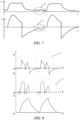
- FIG. 7 is a schematic diagram of waveforms of ineffective effort in the pressure support mode provided by an embodiment of the disclosure. Referring to FIG.
- parts indicated by reference numbers 1 and 2 show waveforms of the ineffective effort, which represent that the user performs an inhalation operation, but since the trigger sensitivity is not reached, the part indicated by the reference number 1 shows the situation that the pressure drops and then rises, the part indicated by the reference number 2 shows the situation that the slope of the flow suddenly increases (exceeds a preset threshold but does not reach the trigger sensitivity) and then becomes smaller, and the time corresponding to a turning point of the pressure change indicated by the reference number 1 and the moment of sudden change in the slope of the flow indicated by the reference number 2 may be the corresponding time of occurrence of an ineffective effort event.
- the ventilator detects that at least one of the following situations has occurred by analyzing waveforms of the acquired ventilation parameters (the airway pressure and the airway flow) over time, it may be determined that an abnormal event of ineffective effort has occurred on the ventilator, that is, it may be determined that the change in the ventilation parameters meets corresponding parameter change conditions:
- the time corresponding to the turning point at which the pressure at the expiratory stage drops and then rises, or the time at which the change rate of the airway flow over time at the expiratory stage exceeds the change rate threshold may be the time of occurrence of an ineffective effort.
- the ventilator may determine the occurrence of the ineffective effort when detecting that a valley appears in an airway pressure-time waveform and/or an accelerated rise appears in a ventilation flow-time waveform at an expiratory stage, and inspiratory trigger of the ventilator is not enabled.
- a pressure-time waveform graph and a flow-time waveform graph corresponding to the ineffective effort event may be stored in the ventilator, a corresponding waveform graph may be obtained by monitoring the airway pressure and/or airway flow during the mechanical ventilation by the ventilator, and the obtained waveform graph may be matched with the stored corresponding waveform graph of ineffective effort.
- the obtained pressure-time waveform graph may be matched with the stored pressure-time waveform graph corresponding to the ineffective effort, and when the similarity obtained by matching reaches a similarity threshold (e.g., 0.9), it may be determined that an abnormal event of ineffective effort has occurred on the ventilator, and thus abnormality prompt information indicating that ineffective effort has occurred on the ventilator may be sent.
- the ventilator may be triggered to enable the inspiratory phase, that is, the ventilator may be triggered to start gas delivery when determining that the abnormal event of ineffective effort has occurred on the ventilator.
- the ventilator may send abnormality prompt information, by means of a user interface (UI) and/or in the form of sound, indicating that the ineffective effort has occurred on the ventilator when determining that the abnormal event of ineffective effort has occurred, so that the user may adjust the trigger sensitivity to better realize the patient-ventilator synchronization.
- UI user interface
- a preset trigger sensitivity adjusting strategy is adopted to adjust the trigger sensitivity of the ventilator when the ventilator determines that the abnormal event of ineffective effort has occurred, for example, the trigger sensitivity is periodically reduced (i.e. in each subsequent respiratory cycle, the trigger sensitivity is reduced to 90% of that in a previous cycle each time) until no ineffective effort event occurs.
- trigger determination may be carried out by determining the change trend of the flow or pressure waveform, if the slope of the flow gradually increases to a certain threshold, it may be considered that an inhalation effort has made to trigger the ventilator to delivery gas.
- the ventilator may be repeatedly triggered within a short time (e.g., 1 s), causing patient-ventilator incoordination, the patient has breathing difficulty and cannot reach a preset tidal volume or minute ventilation volume of the ventilator, and the ventilation quality may be reduced.
- Reasons for the double trigger may include, but are not limited to, the following situations:
- FIG. 8 is a schematic diagram of waveforms of double trigger provided by an embodiment of the disclosure.
- the ventilator may be triggered twice to enable the inspiratory phase in one respiratory cycle, as shown by parts indicated by the reference numbers 3-4 in FIG. 8 .
- the ventilator when the ventilator detects that at least one of the following situations has occurred by analyzing waveforms of the acquired ventilation parameters (the airway pressure and the airway flow) over time, it may be determined that an abnormal event of double trigger has occurred on the ventilator, that is, it may be determined that the change in the ventilation parameters meets corresponding parameter change conditions:
- the third time period described herein may be set according to actual requirements, for example, the third time period may be set to correspond to an exhalation time constant of the patient.
- the ventilator may determine the occurrence of the double trigger when detecting that two sections of inspiratory pressure waveforms appear in the airway pressure-time waveform at an inspiratory stage and/or a short-time expiratory cycle appears between two inspiratory cycles in the airway flow-time waveform.
- the user's expiratory stage herein may be defined by a waveform, and the part in the waveform other than the expiratory stage is the inspiratory stage; and the term short-time refers to a time smaller than a preset time threshold, and the time threshold value may be set according to actual demands, such as twice the time constant, wherein the time constant is equal to the product of an airway resistance and a compliance.
- a pressure-time waveform graph and a flow-time waveform graph corresponding to the double trigger event may be stored in the ventilator, a corresponding waveform graph may be obtained by monitoring the airway pressure and/or airway flow during the mechanical ventilation by the ventilator, and the obtained waveform graph may be matched with the stored corresponding waveform graph of double trigger.
- the obtained pressure-time waveform graph may be matched with the stored pressure-time waveform graph (within one respiratory cycle) corresponding to the double trigger, and when the similarity obtained by matching reaches a similarity threshold (e.g., 0.9), it may be determined that an abnormal event of double trigger has occurred on the ventilator, and thus abnormality prompt information indicating that double trigger has occurred on the ventilator is sent.
- the ventilator may send the abnormality prompt information, by means of a UI and/or in the form of sound, indicating that double trigger has occurred on the ventilator when determining that the abnormal event of double trigger has occurred, so that the user adjusts ventilation (e.g., the tidal volume, the inspiratory pressure or inspiratory time) to better realize the patient-ventilator synchronization.
- ventilation e.g., the tidal volume, the inspiratory pressure or inspiratory time
- a preset ventilation adjusting strategy is adopted to adjust the tidal volume/inspiratory pressure/inspiratory time of ventilation and the inspiratory trigger sensitivity when the ventilator determines that the abnormal event of double trigger has occurred, the trigger sensitivity is periodically reduced (i.e., in each subsequent respiratory cycle, the trigger sensitivity is reduced to 90% of that in a previous cycle each time) until no double trigger event occurs.
- false trigger the patient does not make the inspiratory effort, and due to the fact that the trigger sensitivity of the ventilator is set too low, a pipeline leaks or accumulated water of the line shocks, the pressure in the line changes to trigger the ventilator to delivery gas, which is called self-trigger of the ventilator and also called false trigger.
- Reasons for the false trigger may include, but are not limited to, the following situations:
- FIG. 9 is a schematic diagram of waveforms of the false trigger provided by an embodiment of the disclosure. Referring to FIG. 9 , since the false trigger occurs, changes in the airway pressure and the airway flow may occur repeatedly during gas delivery of the ventilator, as shown by parts indicated by reference numbers 5-6 in FIG. 9 .
- the ventilator when the ventilator detects that at least one of the following situations has occurred by analyzing waveforms of the acquired ventilation parameters (the airway pressure and the airway flow) over time, it may be determined that an abnormal event of false trigger has occurred on the ventilator, that is, it may be determined that the change in the ventilation parameters meets corresponding parameter change conditions:
- a pressure-time waveform graph and a flow-time waveform graph corresponding to the false trigger event may be stored in the ventilator, a corresponding waveform graph may be obtained by monitoring the airway pressure and/or airway flow during the mechanical ventilation by the ventilator, and the obtained waveform graph is matched with the stored corresponding waveform graph of false trigger.
- the obtained pressure-time waveform graph may be matched with the stored pressure-time waveform graph (within one respiratory cycle) corresponding to the false trigger, and when the similarity obtained by matching reaches a similarity threshold (e.g., 0.9), it may be determined that an abnormal event of inspiratory false trigger has occurred on the ventilator, and thus abnormality prompt information indicating that false trigger has occurred on the ventilator is sent.
- the ventilator may send abnormality prompt information, by means of a UI and/or in the form of sound, indicating that the false trigger has occurred on the ventilator when determining that the abnormal event of false trigger has occurred, so that the user adjusts the trigger sensitivity or repair the line to better realize the patient-ventilator synchronization.
- the inspiration-to-expiration switching may be controlled by the medullary respiratory center and may be an involuntary motion, and the abnormal inspiration-to-expiration switching will be caused when the setting of the inspiration-to-expiration switching during the mechanical ventilation does not meet the demand of the patient.
- the situation that the ventilator detects either early switching or delayed switching may prompt that the flow-based switching percentage of the ventilator is set improperly.
- FIG. 10 is a schematic diagram of waveforms of delayed cycling provided by an embodiment of the disclosure. Referring to FIG. 10 , a part indicated by a reference number 7 in FIG.
- a part indicated by a reference number 8 in FIG. 10 may refer to that the patient begins to exhale at the end of inhalation, but the ventilator has not switched to the expiratory phase at this time.
- the exhalation effort may be not sufficient to cause a significant change in pressure, but a sudden drop in the flow, that is, a sudden increase in the change rate of the flow over time, may be obviously detected.
- the ventilator detects that at least one of the following situations has occurred by analyzing waveforms of the acquired ventilation parameters (the airway pressure and the airway flow) over time, it may be determined that an abnormal event of delayed cycling has occurred on the ventilator, that is, it may be determined that the change in the ventilation parameters meets corresponding parameter change conditions:
- the ventilator may determine the occurrence of the delayed cycling when detecting that a rise appears in the airway pressure-waveform or an accelerated drop occurs in a ventilation flow at an inspiration-to-expiration transitional stage.
- a pressure-time waveform graph and a flow-time waveform graph corresponding to the delayed cycling event may be stored in the ventilator, a corresponding waveform graph may be obtained by monitoring the airway pressure and/or airway flow during the mechanical ventilation by the ventilator, and the obtained waveform graph may be matched with the stored corresponding waveform graph of delayed cycling.
- the obtained pressure-time waveform graph may be matched with the stored pressure-time waveform graph (within one respiratory cycle) corresponding to the delayed cycling, and when the similarity obtained by matching reaches a similarity threshold (e.g., 0.9), it may be determined that an abnormal event of inspiratory delayed cycling has occurred on the ventilator, and thus abnormality prompt information indicating that delayed cycling has occurred on the ventilator is sent.
- the ventilator may send abnormality prompt information, by means of a UI and/or in the form of sound, indicating that the delayed cycling has occurred on the ventilator when determining that the abnormal event of delayed cycling (delayed cycling) has occurred, so that the user adjusts the trigger sensitivity to better realize the patient-ventilator synchronization.
- a preset trigger sensitivity adjusting strategy is adopted to adjust the trigger sensitivity of the ventilator when the ventilator determines that the abnormal event of delayed cycling has occurred, thats is, the trigger sensitivity of the ventilator is periodically increased (i.e., in each subsequent respiratory cycle, the trigger sensitivity is increased to 110% of that in a previous cycle each time) until no delayed cycling event occurs.
- the ventilator stops delivering the gas and may be switched for expiration when the patient still performs the inhalation action, causing insufficient inspiration for the patient and the patient-ventilator incoordination. It may be manifested by the flow-time waveform that a descending inspiratory branch may decrease to zero in advance and become an expiratory one, while the expiratory phase at an initial stage has the trend of rising again. If the patient's inhalation effort is strong, repeated trigger of the ventilator may be caused.
- FIG. 11 is a schematic diagram of waveforms of premature cycling provided by an embodiment of the disclosure.
- the ventilator detects that at least one of the following situations has occurred by analyzing waveforms of the acquired ventilation parameters (the airway pressure and the airway flow) over time, it may be determined that an abnormal event of premature cycling has occurred on the ventilator, that is, it may be determined that the change in the ventilation parameters meets corresponding parameter change conditions:
- the ventilator may determine the occurrence of the premature cycling when detecting the situation that a non-monotonic drop appears in the airway pressure-time waveform or a non-monotonic rise appears in the airway flow-time waveform at the inspiration-to-expiration transitional stage.
- a pressure-time waveform graph and a flow-time waveform graph corresponding to the premature cycling event may be stored in the ventilator, a corresponding waveform graph may be obtained by monitoring the airway pressure and/or airway flow during the mechanical ventilation by the ventilator, and the obtained waveform graph may be matched with the stored corresponding waveform graph of premature cycling.
- the obtained pressure-time waveform graph may be matched with the stored pressure-time waveform graph (within one respiratory cycle) corresponding to the premature cycling, and when the similarity obtained by matching reaches a similarity threshold (e.g., 0.9), it may be determined that an abnormal event of inspiratory premature cycling has occurred on the ventilator, and thus abnormality prompt information indicating that premature cycling has occurred on the ventilator is sent.
- the ventilator may send abnormality prompt information, by means of a UI and/or in the form of sound, indicating that the premature cycling has occurred on the ventilator when determining that the abnormal event of premature cycling has occurred, so that the user adjusts the trigger sensitivity to better realize the patient-ventilator synchronization.
- a preset trigger sensitivity adjusting strategy is adopted to adjust the trigger sensitivity of the ventilator when the ventilator determines that the abnormal event of premature cycling has occurred, for example, the trigger sensitivity of the ventilator is periodically reduced (i.e., in each subsequent respiratory cycle, the trigger sensitivity is reduced to 90% of that in a previous cycle each time) until no premature cycling event occurs.
- the ventilation trigger detection apparatus may be provided as a series of modules having a coupling relationship at a signal/information/data level, which will be described below with reference to FIG. 12 .
- FIG. 12 is an optional schematic diagram of constitution of the ventilation trigger detection apparatus provided by the embodiment of the disclosure, showing a series of units included in implementing the ventilation trigger detection apparatus, but the structure of the units of the ventilation trigger detection apparatus is not only limited to that shown in FIG. 12 , for example, the units therein may be further separated or combined according to different functions to be achieved.
- the ventilation trigger detection apparatus includes:
- the processing unit may be further configured to analyze a change trend of the obtained ventilation parameter; and to determine whether patient-ventilator out-of-synchronization occurs during the ventilation according to the change trend of the ventilation parameter.
- the processing unit may be further configured to determine the type of the patient-ventilator out-of-synchronization according to the change trend of the ventilation parameter.
- the type of the patient-ventilator out-of-synchronization includes one or more of ineffective effort, double trigger, false inspiratory trigger, delayed cycling and premature cycling.
- the processing unit may be further configured to determine the occurrence of the ineffective effort when detecting that a valley appears in an airway pressure-time waveform and/or an accelerated rise appears in a ventilation flow-time waveform at an expiratory stage, and inspiratory trigger of a ventilator is not enabled.
- the processing unit may be further configured to determine the occurrence of the double triggerdouble trigger when detecting that two inspiratory pressure waveforms appear in the airway pressure-time waveform at an inspiratory stage and/or a short-time expiratory cycle appears between two inspiratory cycles in the airway flow-time waveform.
- the processing unit may be further configured to determine the occurrence of the delayed cycling when detecting that a rise appears in the airway pressure-time waveform or an accelerated drop occurs in a ventilation flow-time waveform at an inspiration-to-expiration transitional stage.
- the processing unit may be further configured to determine the occurrence of the premature cycling when detecting that a non-monotonic drop appears in the airway pressure-time waveform or a non-monotonic rise appears in the airway flow-time waveform at the inspiration-to-expiration transitional stage.
- the processing unit may be further configured to adjust ventilation trigger setting of the ventilation device or output prompt information about the patient-ventilator out-of-synchronization according to the determined type of the patient-ventilator out-of-synchronization.
- An embodiment of the disclosure may further provide a readable storage medium.
- the storage medium may include: a mobile storage device, a random access memory (RAM), a read-only memory (ROM), a magnetic disk or an optical disk and other media which are capable of storing program codes.
- the readable storage medium stores executable instructions.
- the executable instructions may be configured to implement the ventilation trigger detection method of the example of the disclosure when being executed by the processor.
- the above description relating to the ventilation trigger detection apparatus is similar to the description of the above method and the same as the description of the beneficial effects of the method, which will not be described in detail.
- Technical details not disclosed in the embodiments of the ventilation trigger detection apparatus according to the disclosure may be referred to the description of the examples of the method according to the disclosure.
- All or some of the steps of the embodiments may be completed by a program that instructs related hardware.
- the program may be stored in a computer readable storage medium. When the program is executed, the steps including the above method examples are performed.
- the foregoing storage medium includes: a mobile storage device, a random access memory, a read-only memory, a magnetic disk or an optical disk and other media which are capable of storing program codes.
- the above integrated unit of the disclosure may also be stored in a computer readable storage medium.
- the computer software product is stored in a storage medium, including several instructions for instructing a computer device (which may be a personal computer, a server, or a network device) to perform all or some of the methods in the examples of the disclosure.
- the foregoing storage medium includes: a mobile storage device, a RAM, a ROM, a magnetic disk or an optical disk and other media which are capable of storing program codes.
Landscapes
- Health & Medical Sciences (AREA)
- Engineering & Computer Science (AREA)
- Biomedical Technology (AREA)
- Public Health (AREA)
- Life Sciences & Earth Sciences (AREA)
- General Health & Medical Sciences (AREA)
- Medical Informatics (AREA)
- Animal Behavior & Ethology (AREA)
- Heart & Thoracic Surgery (AREA)
- Veterinary Medicine (AREA)
- Pulmonology (AREA)
- Pathology (AREA)
- Primary Health Care (AREA)
- Epidemiology (AREA)
- Surgery (AREA)
- Hematology (AREA)
- Anesthesiology (AREA)
- Emergency Medicine (AREA)
- Molecular Biology (AREA)
- Biophysics (AREA)
- Physics & Mathematics (AREA)
- Physiology (AREA)
- Psychiatry (AREA)
- Signal Processing (AREA)
- Nuclear Medicine, Radiotherapy & Molecular Imaging (AREA)
- Urology & Nephrology (AREA)
- Computer Vision & Pattern Recognition (AREA)
- Artificial Intelligence (AREA)
- Business, Economics & Management (AREA)
- General Business, Economics & Management (AREA)
- Data Mining & Analysis (AREA)
- Databases & Information Systems (AREA)
- Measurement Of The Respiration, Hearing Ability, Form, And Blood Characteristics Of Living Organisms (AREA)
Claims (3)
- Ein Computerprogramm zur Erkennung von Beatmungstriggern mit Anweisungen, die ein Beatmungsgerät dazu veranlassen, die folgenden Schritte auszuführen:Überwachen der Beatmungsparameter während einer mechanischen Beatmung eines Patienten, wobei die Beatmungsparameter einem Atemwegsdruck und einer Atemwegsströmungsgeschwindigkeit entsprechen; undBestimmen der Synchronität von Patient und Beatmungsgerät während der mechanischen Beatmung anhand einer Änderung der Beatmungsparameter, indem festgestellt wird, ob eine Änderung der Beatmungsparameter eine Bedingung für eine Parameteränderung erfüllt;Erfassen der Wellenformen jedes Beatmungsparameters im Laufe der Zeit während der mechanischen Beatmung;Ausführen eines Ähnlichkeitsvergleichs der erfassten Wellenformen der Beatmungsparameter und gespeicherten Wellenformen der entsprechenden Beatmungsparameter, um eine Ähnlichkeit zwischen den erfassten Wellenformen der Beatmungsparameter und den gespeicherten Wellenformen der entsprechenden Beatmungsparameter zu ermitteln;Feststellen, dass die Änderung der Beatmungsparameter die Bedingung für die Parameteränderung erfüllt, wenn die durch den Abgleich erzielte Ähnlichkeit einen Schwellenwert der Wellenformähnlichkeit erreicht;wobei die erfassten Wellenformen der Beatmungsparameter und die gespeicherten Wellenformen der entsprechenden Beatmungsparameter eine Atemwegsdruck-Zeit-Wellenform und eine Atemwegsfluss-Zeit-Wellenform umfassen, die einem oder mehreren der folgenden Ereignisse entsprechen, wie:einer erfolgslosen Anstrengung;einem Doppeltrigger;einem Fehltrigger;einem verzögerten Zyklus;und einem vorzeitigen Zyklus; und ferner:
Bestimmen einer Fehlsynchronisation zwischen Patient und Beatmungsgerät, wenn die Änderung des Beatmungsparameters die Bedingung der Parameteränderung erfüllt:Anpassen einer Beatmungstrigger-Einstellung des Beatmungsgeräts, nachdem eine Art der Fehlsynchronisation zwischen Patient und Beatmungsgerät gemäß einem Änderungstrend der Beatmungsparameter bestimmt wurde, oderAusgabe einer Hinweisinformation über die Fehlsynchronisation zwischen Patient und Beatmungsgerät gemäß der bestimmten Art einer Fehlsynchronisation zwischen Patient und Beatmungsgerät, nachdem eine Art der Fehlsynchronisation gemäß einem Änderungstrend der Beatmungsparameter bestimmt wurde; undregelmäßige Reduzierung der Empfindlichkeit des Einatmungstriggers des Beatmungsgeräts in jedem nachfolgenden Atemzyklus, wenn eine erfolglose Anstrengung auftritt, bis keine erfolglose Anstrengung mehr auftritt;regelmäßige Reduzierung der Empfindlichkeit des Einatmungstriggers des Beatmungsgeräts in jedem nachfolgenden Atemzyklus, wenn ein Einatmungsdoppeltrigger auftritt, bis kein Doppeltrigger-Ereignis mehr auftritt;regelmäßiges Erhöhen der Empfindlichkeit des Einatmungstriggers des Beatmungsgeräts in jedem nachfolgenden Atemzyklus, wenn ein verzögerter Ausatmungszyklus auftritt, bis kein weiteres verzögertes Zyklusereignis mehr auftritt;regelmäßige Reduzierung der Empfindlichkeit des Einatmungstriggers des Beatmungsgeräts in jedem nachfolgenden Atemzyklus, wenn ein vorzeitiger Ausatmungs-Zyklus auftritt, bis kein weiterer vorzeitiger Zyklus mehr auftritt. - Eine Vorrichtung zur Erkennung des Beatmungstriggers (100), die in einem Beatmungsgerät verwendet wird, mit der Eigenschaft, dass die Vorrichtung Folgendes umfasst:eine Parameterüberwachungseinheit (121), die so konfiguriert ist, dass sie während der mechanischen Beatmung eines Patienten Beatmungsparameter überwacht, wobei die Beatmungsparameter dem Atemwegsdruck und der Atemwegsdurchflussgeschwindigkeit entsprechen; undeine Verarbeitungseinheit (122), die so konfiguriert ist, dass sie die Synchronität zwischen Patient und Beatmungsgerät während der mechanischen Beatmung gemäß einer Änderung der Beatmungsparameter bestimmt, indem festgestellt wird, ob eine Änderung der Beatmungsparameter eine Bedingung der Parameteränderung erfüllt; wobei die Verarbeitungseinheit (122) ferner so konfiguriert ist, dass sie:eine Wellenform jedes Beatmungsparameters im Laufe der Zeit während der mechanischen Beatmung erfasst;einen Ähnlichkeitsvergleich zwischen den erfassten Wellenformen der Beatmungsparameter und den gespeicherten Wellenformen der entsprechenden Beatmungsparameter ausführt, um eine Ähnlichkeit zwischen den erfassten Wellenformen der Beatmungsparameter und den gespeicherten Wellenformen der entsprechenden Beatmungsparameter zu bestimmen, undfeststellt, dass die Änderung der Beatmungsparameter die Bedingung der Parameteränderung erfüllt, wenn die durch den Abgleich erzielte Ähnlichkeit einen Schwellenwert der Wellenformähnlichkeit erreicht;wobei die erfassten Wellenformen der Beatmungsparameter und die gespeicherten Wellenformen der entsprechenden Beatmungsparameter eine Atemwegsdruck-Zeit-Wellenform und eine Atemwegsfluss-Zeit-Wellenform umfassen, die einem oder mehreren der folgenden Ereignisse entsprechen, wie:einer erfolgslosen Anstrengung;einem Doppeltrigger;einem Fehltrigger;einem verzögerten Zyklus;und einem vorzeitigen Zyklus; unddie Verarbeitungseinheit (122) ferner so konfiguriert ist, dass sie:eine Fehlsynchronisation zwischen Patient und Beatmungsgerät bestimmt, wenn die Änderung des Beatmungsparameters die Bedingung der Parameteränderung erfüllt,
die Beatmungstrigger-Einstellung des Beatmungsgeräts anpasst, nachdem eine Art der Fehlsynchronisation zwischen Patient und Beatmungsgerät gemäß einem Änderungstrend der Beatmungsparameter bestimmt wurde, odereine Hinweisinformation über die Fehlsynchronisation zwischen Patient und Beatmungsgerät gemäß der bestimmten Art der Fehlsynchronisation ausgibt, nachdem eine Art der Fehlsynchronisation gemäß einem Änderungstrend der Beatmungsparameter bestimmt wurde;die Empfindlichkeit des Einatmungstriggers des Beatmungsgeräts in jedem nachfolgenden Atemzyklus regelmäßig reduziert, wenn eine erfolglose Anstrengung auftritt, bis keine erfolglose Anstrengung mehr auftritt;die Empfindlichkeit des Einatmungstriggers des Beatmungsgeräts in jedem nachfolgenden Atemzyklus regelmäßig reduziert, wenn ein Einatmungsdoppeltrigger auftritt, bis kein Doppeltrigger-Ereignis mehr auftrittdie Empfindlichkeit des Einatmungstriggers des Beatmungsgeräts in jedem nachfolgenden Atemzyklus regelmäßig erhöht, wenn ein verzögerter Ausatmungszyklus auftritt, bis kein weiteres verzögertes Zyklusereignis mehr auftrit;die Empfindlichkeit des Einatmungstriggers des Beatmungsgeräts in jedem nachfolgenden Atemzyklus regelmäßig reduziert, wenn ein vorzeitiger Ausatmungs-Zyklus auftritt, bis kein weiterer vorzeitiger Zyklus mehr auftritt. - Ein Beatmungsgerät mit einer Vorrichtung zur Erkennung des Beatmungstriggers (100), einer Gasquelle (160), einem Inspirationsschenkel (170), einem Exspirationsschenkel (180), und einer Atemleitung (190), wobei:die Gasquelle (160) während der mechanischen Beatmung Gas liefert;der Inspirationsschenkel (170) mit der Gasquelle (160) verbunden ist, um während der mechanischen Beatmung einen Einatmungsweg zu schaffen;der Exspirationsschenkel (180) während der mechanischen Beatmung einen Ausatmungsweg schafft;die Atemleitung (190) sowohl mit dem Inspirationsschenkel (170) als auch mit dem Exspirationsschenkel (180) verbunden ist und verwendet wird, um einem Patienten während der mechanischen Beatmung Gas zuzuführen oder von ihm abzuleiten;die Vorrichtung zur Erkennung des Beatmungstriggers (100) jeweils mit dem Inspirationsschenkel (170) und dem Exspirationsschenkel (180) verbunden ist und Folgendes umfasst:eine Parameterüberwachungseinheit (121), die so konfiguriert ist, dass sie während der mechanischen Beatmung eines Patienten Beatmungsparameter überwacht, wobei die Beatmungsparameter dem Atemwegsdruck und der Atemwegsdurchflussgeschwindigkeit entsprechen;eine Verarbeitungseinheit (122), die so konfiguriert ist, dass sie die Synchronität zwischen Patient und Beatmungsgerät während der mechanischen Beatmung gemäß einer Änderung der Beatmungsparameter bestimmt, indem festgestellt wird, ob eine Änderung der Beatmungsparameter eine Bedingung der Parameteränderung erfüllt;wobei die Verarbeitungseinheit (122) ferner so konfiguriert ist, dass sie:Wellenformen jedes Beatmungsparameters im Laufe der Zeit während der mechanischen Beatmung erfasst;einen Ähnlichkeitsvergleich zwischen den erfassten Wellenformen der Beatmungsparameter und den gespeicherten Wellenformen der entsprechenden Beatmungsparameter ausführt, um eine Ähnlichkeit zwischen den erfassten Wellenformen der Beatmungsparameter und den gespeicherten Wellenformen der entsprechenden Beatmungsparameter zu bestimmen;feststellt, dass die Änderung der Beatmungsparameter die Bedingung der Parameteränderung erfüllt, wenn die durch den Abgleich erzielte Ähnlichkeit einen Schwellenwert der Wellenformähnlichkeit erreicht;
wobei die erfassten Wellenformen der Beatmungsparameter und die gespeicherten Wellenformen der entsprechenden Beatmungsparameter eine Atemwegsdruck-Zeit-Wellenform undeine Atemwegsfluss-Zeit-Wellenform umfassen, die einem oder mehreren der folgenden Ereignisse entsprechen, wie:einer erfolgslosen Anstrengung;einem Doppeltrigger;einem Fehltrigger;einem verzögerten Zyklus;und einem vorzeitigen Zyklus; unddie Verarbeitungseinheit (122) ferner so konfiguriert ist, dass sie:eine Fehlsynchronisation zwischen Patient und Beatmungsgerät bestimmt, wenn die Änderung des Beatmungsparameters die Bedingung der Parameteränderung erfüllt,die Beatmungstrigger-Einstellung des Beatmungsgeräts anpasst, nachdem eine Art der Fehlsynchronisation zwischen Patient und Beatmungsgerät gemäß einem Änderungstrend der Beatmungsparameter bestimmt wurde, odereine Hinweisinformation über die Fehlsynchronisation zwischen Patient und Beatmungsgerät gemäß der bestimmten Art der Fehlsynchronisation ausgibt, nachdem eine Art der Fehlsynchronisation gemäß einem Änderungstrend der Beatmungsparameter bestimmt wurde;wobei die Verarbeitungseinheit (122) ferner so konfiguriert ist, dass sie:die Empfindlichkeit des Einatmungstriggers des Beatmungsgeräts in jedem nachfolgenden Atemzyklus regelmäßig reduziert, wenn eine erfolglose Anstrengung auftritt, bis keine erfolglose Anstrengung mehr auftritt;die Empfindlichkeit des Einatmungstriggers des Beatmungsgeräts in jedem nachfolgenden Atemzyklus regelmäßig reduziert, wenn ein Einatmungsdoppeltrigger auftritt, bis kein Doppeltrigger-Ereignis mehr auftrittdie Empfindlichkeit des Einatmungstriggers des Beatmungsgeräts in jedem nachfolgenden Atemzyklus regelmäßig erhöht, wenn ein verzögerter Ausatmungszyklus auftritt, bis kein weiteres verzögertes Zyklusereignis mehr auftrit;die Empfindlichkeit des Einatmungstriggers des Beatmungsgeräts in jedem nachfolgenden Atemzyklus regelmäßig reduziert, wenn ein vorzeitiger Ausatmungs-Zyklus auftritt, bis kein weiterer vorzeitiger Zyklus mehr auftritt.
Applications Claiming Priority (1)
| Application Number | Priority Date | Filing Date | Title |
|---|---|---|---|
| PCT/CN2018/101606 WO2020037519A1 (zh) | 2018-08-21 | 2018-08-21 | 通气触发检测方法、装置、通气设备及存储介质 |
Publications (3)
| Publication Number | Publication Date |
|---|---|
| EP3834871A1 EP3834871A1 (de) | 2021-06-16 |
| EP3834871A4 EP3834871A4 (de) | 2021-12-08 |
| EP3834871B1 true EP3834871B1 (de) | 2025-04-16 |
Family
ID=69592015
Family Applications (1)
| Application Number | Title | Priority Date | Filing Date |
|---|---|---|---|
| EP18931204.4A Active EP3834871B1 (de) | 2018-08-21 | 2018-08-21 | Computerprogramm zur erkennung des ventilatorauslösers, vorrichtung zur erkennung des ventilatorauslösers und ventilator |
Country Status (4)
| Country | Link |
|---|---|
| US (1) | US20210154423A1 (de) |
| EP (1) | EP3834871B1 (de) |
| CN (1) | CN112449607B (de) |
| WO (1) | WO2020037519A1 (de) |
Families Citing this family (12)
| Publication number | Priority date | Publication date | Assignee | Title |
|---|---|---|---|---|
| CN117642199A (zh) * | 2021-07-26 | 2024-03-01 | 深圳迈瑞生物医疗电子股份有限公司 | 医疗通气设备及其通气控制方法、存储介质 |
| CN117642200A (zh) * | 2021-08-20 | 2024-03-01 | 深圳迈瑞生物医疗电子股份有限公司 | 一种通气设备及压力上升时间的调节方法 |
| US20230078506A1 (en) * | 2021-09-16 | 2023-03-16 | Covidien Lp | Automatic synchronization for medical ventilation |
| CN118159322A (zh) * | 2021-12-09 | 2024-06-07 | 深圳迈瑞生物医疗电子股份有限公司 | 医疗设备及通气状态识别方法 |
| CN114404753B (zh) * | 2022-01-24 | 2023-09-26 | 湖南比扬医疗科技有限公司 | 一种呼吸机吸气检测方法、装置及计算机可读存储介质 |
| CN114618060B (zh) * | 2022-03-10 | 2024-11-26 | 湖南万脉医疗科技有限公司 | 一种基于事件检测的呼吸机控制方法 |
| CN117642204A (zh) * | 2022-04-11 | 2024-03-01 | 深圳迈瑞生物医疗电子股份有限公司 | 一种通气装置及呼吸监测方法 |
| CN117482342A (zh) * | 2022-07-26 | 2024-02-02 | 深圳迈瑞生物医疗电子股份有限公司 | 一种控制通气设备的方法和通气设备 |
| CN116328122A (zh) * | 2023-03-22 | 2023-06-27 | 深圳市科曼医疗设备有限公司 | 触发阈值的调节方法及装置、设备及存储介质 |
| CN116370769B (zh) * | 2023-06-07 | 2023-08-22 | 深圳市普博医疗科技股份有限公司 | 一种通气设备、方法及存储介质 |
| CN119950913B (zh) * | 2025-02-08 | 2026-04-03 | 深圳市科曼医疗设备有限公司 | 基于流速的呼吸机触发控制方法、系统、设备及存储介质 |
| CN121008616B (zh) * | 2025-10-24 | 2026-02-17 | 中南大学 | 一种列车-隧道耦合瞬态压力波动的模拟方法及系统 |
Family Cites Families (27)
| Publication number | Priority date | Publication date | Assignee | Title |
|---|---|---|---|---|
| AU2006343578B2 (en) * | 2006-05-12 | 2012-05-03 | Yrt Limited | Method and device for generating a signal that reflects respiratory efforts in patients on ventilatory support |
| US9392964B2 (en) * | 2009-04-22 | 2016-07-19 | Resmed Limited | Detection of asynchrony |
| KR101138958B1 (ko) * | 2010-02-17 | 2012-04-25 | 주식회사 멕 아이씨에스 | 인공 호흡기의 유속 방향 조절 장치 |
| US20180280646A1 (en) * | 2010-08-13 | 2018-10-04 | Respiratory Motion, Inc. | Respiratory volume monitor and ventilator |
| US8573207B2 (en) * | 2010-09-28 | 2013-11-05 | Guillermo Gutierrez | Method and system to detect respiratory asynchrony |
| US8757153B2 (en) * | 2010-11-29 | 2014-06-24 | Covidien Lp | Ventilator-initiated prompt regarding detection of double triggering during ventilation |
| CN102266614A (zh) * | 2010-12-31 | 2011-12-07 | 北京谊安医疗系统股份有限公司 | 吸气触发控制方法及装置、呼吸机 |
| US8783250B2 (en) * | 2011-02-27 | 2014-07-22 | Covidien Lp | Methods and systems for transitory ventilation support |
| US20130006134A1 (en) * | 2011-06-30 | 2013-01-03 | Nellcor Puritan Bennett Llc | Methods and systems for monitoring volumetric carbon dioxide |
| US20130006133A1 (en) * | 2011-06-30 | 2013-01-03 | Nellcor Puritan Bennett Llc | Methods and systems for monitoring volumetric carbon dioxide |
| US9027552B2 (en) * | 2012-07-31 | 2015-05-12 | Covidien Lp | Ventilator-initiated prompt or setting regarding detection of asynchrony during ventilation |
| RS20120373A1 (en) * | 2012-08-30 | 2014-04-30 | Diasens Doo | APPARATUS AND PROCEDURE FOR MONITORING BREATHING VOLUME AND SYNCHRONIZING ACTIVATION IN MECHANICAL VENTILATION BY MEASURING LOCAL BURDEN OF THE TORSIS SURFACE |
| US20140150795A1 (en) * | 2012-11-30 | 2014-06-05 | Covidien Lp | System and method for detecting double triggering with remote monitoring |
| US20140261424A1 (en) * | 2013-03-13 | 2014-09-18 | Covidien Lp | Methods and systems for phase shifted pressure ventilation |
| US10064583B2 (en) * | 2013-08-07 | 2018-09-04 | Covidien Lp | Detection of expiratory airflow limitation in ventilated patient |
| US20150090258A1 (en) * | 2013-10-01 | 2015-04-02 | Covidien Lp | Ventilator-initiated prompt or setting regarding detection of asynchrony during ventilation |
| CN106029141B (zh) * | 2014-01-09 | 2018-11-09 | 皇家飞利浦有限公司 | 患者-通气机异步性检测 |
| CN103920215B (zh) * | 2014-05-04 | 2015-08-26 | 湖南明康中锦医疗科技发展有限公司 | 一种气体流发生器送气触发方法 |
| EP2985710A1 (de) * | 2014-08-11 | 2016-02-17 | Mindray Medical Sweden AB | Steuerungsvorrichtung für medizinische Beatmungsgeräte |
| US10722670B2 (en) * | 2014-10-28 | 2020-07-28 | Fisher & Paykel Healthcare Limited | Patient specific auto-flowrate control |
| CN107949411B (zh) * | 2015-08-26 | 2021-05-28 | 皇家飞利浦有限公司 | 机械吸气-呼气 |
| EP3413965B1 (de) * | 2015-12-14 | 2024-01-31 | Stimdia Medical, Inc. | Elektrische stimulation zur konservierung und wiederherstellung einer membranfunktion |
| EP3416543A1 (de) * | 2016-02-18 | 2018-12-26 | Koninklijke Philips N.V. | Verbesserte schätzung von respiratorischen parametern und asynchroniedetekionsalgorithmen mittels manometrie des zentralen venendrucks |
| EP4245217A3 (de) * | 2016-11-11 | 2023-12-06 | The Regents of The University of California | Asynchroner reanimations- und beatmungsmonitor |
| CN106840734B (zh) * | 2017-04-11 | 2019-06-11 | 湖南明康中锦医疗科技发展有限公司 | 一种呼吸机跟随性能的评估方法、装置以及无创呼吸机 |
| US20190015614A1 (en) * | 2017-07-13 | 2019-01-17 | Royal Commission Yanbu Colleges & Institutes | Systems, devices, and methodologies to provide protective and personalized ventilation |
| CN118142041A (zh) * | 2017-11-22 | 2024-06-07 | 费雪派克医疗保健有限公司 | 用于呼吸流治疗系统的呼吸速率监测 |
-
2018
- 2018-08-21 CN CN201880094809.1A patent/CN112449607B/zh active Active
- 2018-08-21 EP EP18931204.4A patent/EP3834871B1/de active Active
- 2018-08-21 WO PCT/CN2018/101606 patent/WO2020037519A1/zh not_active Ceased
-
2021
- 2021-02-07 US US17/169,524 patent/US20210154423A1/en not_active Abandoned
Also Published As
| Publication number | Publication date |
|---|---|
| US20210154423A1 (en) | 2021-05-27 |
| CN112449607A (zh) | 2021-03-05 |
| WO2020037519A1 (zh) | 2020-02-27 |
| CN112449607B (zh) | 2023-05-05 |
| EP3834871A1 (de) | 2021-06-16 |
| EP3834871A4 (de) | 2021-12-08 |
Similar Documents
| Publication | Publication Date | Title |
|---|---|---|
| US20210154423A1 (en) | Ventilation trigger detection method and apparatus, ventilation device | |
| US11027080B2 (en) | System and method for determining ventilator leakage during stable periods within a breath | |
| US8272379B2 (en) | Leak-compensated flow triggering and cycling in medical ventilators | |
| US20220409836A1 (en) | Systems and methods for respiratory effort detection utilizing signal distortion | |
| JP5779506B2 (ja) | 機械呼吸機能付圧力支持システム | |
| US20120304995A1 (en) | Previous Set Up Mode Parameter Retention | |
| US9925346B2 (en) | Systems and methods for ventilation with unknown exhalation flow | |
| US20100218766A1 (en) | Customizable mandatory/spontaneous closed loop mode selection | |
| US20140000606A1 (en) | Methods and systems for mimicking fluctuations in delivered flow and/or pressure during ventilation | |
| US20140261424A1 (en) | Methods and systems for phase shifted pressure ventilation | |
| RU2594808C2 (ru) | Система и способ для лечения синдрома гиповентиляции при ожирении | |
| JP6165632B2 (ja) | 被検体に強制吸気−呼気を提供するシステム及び方法 | |
| WO2013016608A1 (en) | Methods and systems for model-based transformed proportional assist ventilation | |
| CN110049799A (zh) | 用于驱动压力自发通气的方法和系统 | |
| JP2014506163A5 (de) | ||
| JP2016523586A5 (de) | ||
| JP2016523586A (ja) | 呼吸蓄積療法に対する圧力支持システム | |
| US20130340751A1 (en) | Measuring continuity of therapy associated with a respiratory treatment device | |
| CN103260682A (zh) | 取决于呼吸速率的呼吸辅助 | |
| CN106823085A (zh) | 一种保证呼吸机潮气量的压力控制方法 | |
| US20230078506A1 (en) | Automatic synchronization for medical ventilation | |
| CN112999479A (zh) | 呼吸机吸气触发方法及应用 | |
| WO2023042064A1 (en) | Automatic synchronization for medical ventilation |
Legal Events
| Date | Code | Title | Description |
|---|---|---|---|
| STAA | Information on the status of an ep patent application or granted ep patent |
Free format text: STATUS: THE INTERNATIONAL PUBLICATION HAS BEEN MADE |
|
| PUAI | Public reference made under article 153(3) epc to a published international application that has entered the european phase |
Free format text: ORIGINAL CODE: 0009012 |
|
| STAA | Information on the status of an ep patent application or granted ep patent |
Free format text: STATUS: REQUEST FOR EXAMINATION WAS MADE |
|
| 17P | Request for examination filed |
Effective date: 20210308 |
|
| AK | Designated contracting states |
Kind code of ref document: A1 Designated state(s): AL AT BE BG CH CY CZ DE DK EE ES FI FR GB GR HR HU IE IS IT LI LT LU LV MC MK MT NL NO PL PT RO RS SE SI SK SM TR |
|
| TPAC | Observations filed by third parties |
Free format text: ORIGINAL CODE: EPIDOSNTIPA |
|
| DAV | Request for validation of the european patent (deleted) | ||
| DAX | Request for extension of the european patent (deleted) | ||
| A4 | Supplementary search report drawn up and despatched |
Effective date: 20211108 |
|
| RIC1 | Information provided on ipc code assigned before grant |
Ipc: G16H 50/20 20180101ALI20211102BHEP Ipc: G16H 40/67 20180101ALI20211102BHEP Ipc: G16H 20/40 20180101ALI20211102BHEP Ipc: A61B 5/00 20060101ALI20211102BHEP Ipc: A61B 5/087 20060101ALI20211102BHEP Ipc: A61M 16/00 20060101AFI20211102BHEP |
|
| STAA | Information on the status of an ep patent application or granted ep patent |
Free format text: STATUS: EXAMINATION IS IN PROGRESS |
|
| 17Q | First examination report despatched |
Effective date: 20220916 |
|
| GRAP | Despatch of communication of intention to grant a patent |
Free format text: ORIGINAL CODE: EPIDOSNIGR1 |
|
| STAA | Information on the status of an ep patent application or granted ep patent |
Free format text: STATUS: GRANT OF PATENT IS INTENDED |
|
| INTG | Intention to grant announced |
Effective date: 20241023 |
|
| GRAS | Grant fee paid |
Free format text: ORIGINAL CODE: EPIDOSNIGR3 |
|
| GRAA | (expected) grant |
Free format text: ORIGINAL CODE: 0009210 |
|
| STAA | Information on the status of an ep patent application or granted ep patent |
Free format text: STATUS: THE PATENT HAS BEEN GRANTED |
|
| AK | Designated contracting states |
Kind code of ref document: B1 Designated state(s): AL AT BE BG CH CY CZ DE DK EE ES FI FR GB GR HR HU IE IS IT LI LT LU LV MC MK MT NL NO PL PT RO RS SE SI SK SM TR |
|
| REG | Reference to a national code |
Ref country code: GB Ref legal event code: FG4D |
|
| REG | Reference to a national code |
Ref country code: CH Ref legal event code: EP |
|
| REG | Reference to a national code |
Ref country code: IE Ref legal event code: FG4D |
|
| REG | Reference to a national code |
Ref country code: DE Ref legal event code: R096 Ref document number: 602018081229 Country of ref document: DE |
|
| P01 | Opt-out of the competence of the unified patent court (upc) registered |
Free format text: CASE NUMBER: APP_16741/2025 Effective date: 20250420 |
|
| REG | Reference to a national code |
Ref country code: NL Ref legal event code: MP Effective date: 20250416 |
|
| PG25 | Lapsed in a contracting state [announced via postgrant information from national office to epo] |
Ref country code: NL Free format text: LAPSE BECAUSE OF FAILURE TO SUBMIT A TRANSLATION OF THE DESCRIPTION OR TO PAY THE FEE WITHIN THE PRESCRIBED TIME-LIMIT Effective date: 20250416 |
|
| REG | Reference to a national code |
Ref country code: AT Ref legal event code: MK05 Ref document number: 1785129 Country of ref document: AT Kind code of ref document: T Effective date: 20250416 |
|
| PG25 | Lapsed in a contracting state [announced via postgrant information from national office to epo] |
Ref country code: PT Free format text: LAPSE BECAUSE OF FAILURE TO SUBMIT A TRANSLATION OF THE DESCRIPTION OR TO PAY THE FEE WITHIN THE PRESCRIBED TIME-LIMIT Effective date: 20250818 Ref country code: FI Free format text: LAPSE BECAUSE OF FAILURE TO SUBMIT A TRANSLATION OF THE DESCRIPTION OR TO PAY THE FEE WITHIN THE PRESCRIBED TIME-LIMIT Effective date: 20250416 Ref country code: ES Free format text: LAPSE BECAUSE OF FAILURE TO SUBMIT A TRANSLATION OF THE DESCRIPTION OR TO PAY THE FEE WITHIN THE PRESCRIBED TIME-LIMIT Effective date: 20250416 |
|
| PGFP | Annual fee paid to national office [announced via postgrant information from national office to epo] |
Ref country code: DE Payment date: 20250820 Year of fee payment: 8 |
|
| REG | Reference to a national code |
Ref country code: LT Ref legal event code: MG9D |
|
| PG25 | Lapsed in a contracting state [announced via postgrant information from national office to epo] |
Ref country code: NO Free format text: LAPSE BECAUSE OF FAILURE TO SUBMIT A TRANSLATION OF THE DESCRIPTION OR TO PAY THE FEE WITHIN THE PRESCRIBED TIME-LIMIT Effective date: 20250716 Ref country code: GR Free format text: LAPSE BECAUSE OF FAILURE TO SUBMIT A TRANSLATION OF THE DESCRIPTION OR TO PAY THE FEE WITHIN THE PRESCRIBED TIME-LIMIT Effective date: 20250717 |
|
| PG25 | Lapsed in a contracting state [announced via postgrant information from national office to epo] |
Ref country code: PL Free format text: LAPSE BECAUSE OF FAILURE TO SUBMIT A TRANSLATION OF THE DESCRIPTION OR TO PAY THE FEE WITHIN THE PRESCRIBED TIME-LIMIT Effective date: 20250416 |
|
| PG25 | Lapsed in a contracting state [announced via postgrant information from national office to epo] |
Ref country code: BG Free format text: LAPSE BECAUSE OF FAILURE TO SUBMIT A TRANSLATION OF THE DESCRIPTION OR TO PAY THE FEE WITHIN THE PRESCRIBED TIME-LIMIT Effective date: 20250416 |
|
| PG25 | Lapsed in a contracting state [announced via postgrant information from national office to epo] |
Ref country code: HR Free format text: LAPSE BECAUSE OF FAILURE TO SUBMIT A TRANSLATION OF THE DESCRIPTION OR TO PAY THE FEE WITHIN THE PRESCRIBED TIME-LIMIT Effective date: 20250416 |
|
| PG25 | Lapsed in a contracting state [announced via postgrant information from national office to epo] |
Ref country code: AT Free format text: LAPSE BECAUSE OF FAILURE TO SUBMIT A TRANSLATION OF THE DESCRIPTION OR TO PAY THE FEE WITHIN THE PRESCRIBED TIME-LIMIT Effective date: 20250416 |
|
| PG25 | Lapsed in a contracting state [announced via postgrant information from national office to epo] |
Ref country code: RS Free format text: LAPSE BECAUSE OF FAILURE TO SUBMIT A TRANSLATION OF THE DESCRIPTION OR TO PAY THE FEE WITHIN THE PRESCRIBED TIME-LIMIT Effective date: 20250716 |
|
| PG25 | Lapsed in a contracting state [announced via postgrant information from national office to epo] |
Ref country code: IS Free format text: LAPSE BECAUSE OF FAILURE TO SUBMIT A TRANSLATION OF THE DESCRIPTION OR TO PAY THE FEE WITHIN THE PRESCRIBED TIME-LIMIT Effective date: 20250816 |
|
| PG25 | Lapsed in a contracting state [announced via postgrant information from national office to epo] |
Ref country code: LV Free format text: LAPSE BECAUSE OF FAILURE TO SUBMIT A TRANSLATION OF THE DESCRIPTION OR TO PAY THE FEE WITHIN THE PRESCRIBED TIME-LIMIT Effective date: 20250416 |
|
| PG25 | Lapsed in a contracting state [announced via postgrant information from national office to epo] |
Ref country code: DK Free format text: LAPSE BECAUSE OF FAILURE TO SUBMIT A TRANSLATION OF THE DESCRIPTION OR TO PAY THE FEE WITHIN THE PRESCRIBED TIME-LIMIT Effective date: 20250416 Ref country code: SM Free format text: LAPSE BECAUSE OF FAILURE TO SUBMIT A TRANSLATION OF THE DESCRIPTION OR TO PAY THE FEE WITHIN THE PRESCRIBED TIME-LIMIT Effective date: 20250416 |
|
| REG | Reference to a national code |
Ref country code: DE Ref legal event code: R097 Ref document number: 602018081229 Country of ref document: DE |
|
| PG25 | Lapsed in a contracting state [announced via postgrant information from national office to epo] |
Ref country code: CZ Free format text: LAPSE BECAUSE OF FAILURE TO SUBMIT A TRANSLATION OF THE DESCRIPTION OR TO PAY THE FEE WITHIN THE PRESCRIBED TIME-LIMIT Effective date: 20250416 |
|
| PG25 | Lapsed in a contracting state [announced via postgrant information from national office to epo] |
Ref country code: EE Free format text: LAPSE BECAUSE OF FAILURE TO SUBMIT A TRANSLATION OF THE DESCRIPTION OR TO PAY THE FEE WITHIN THE PRESCRIBED TIME-LIMIT Effective date: 20250416 |
|
| PG25 | Lapsed in a contracting state [announced via postgrant information from national office to epo] |
Ref country code: SK Free format text: LAPSE BECAUSE OF FAILURE TO SUBMIT A TRANSLATION OF THE DESCRIPTION OR TO PAY THE FEE WITHIN THE PRESCRIBED TIME-LIMIT Effective date: 20250416 Ref country code: RO Free format text: LAPSE BECAUSE OF FAILURE TO SUBMIT A TRANSLATION OF THE DESCRIPTION OR TO PAY THE FEE WITHIN THE PRESCRIBED TIME-LIMIT Effective date: 20250416 |
|
| PG25 | Lapsed in a contracting state [announced via postgrant information from national office to epo] |
Ref country code: IT Free format text: LAPSE BECAUSE OF FAILURE TO SUBMIT A TRANSLATION OF THE DESCRIPTION OR TO PAY THE FEE WITHIN THE PRESCRIBED TIME-LIMIT Effective date: 20250416 |
|
| PLBE | No opposition filed within time limit |
Free format text: ORIGINAL CODE: 0009261 |
|
| STAA | Information on the status of an ep patent application or granted ep patent |
Free format text: STATUS: NO OPPOSITION FILED WITHIN TIME LIMIT |
|
| REG | Reference to a national code |
Ref country code: CH Ref legal event code: L10 Free format text: ST27 STATUS EVENT CODE: U-0-0-L10-L00 (AS PROVIDED BY THE NATIONAL OFFICE) Effective date: 20260225 |
|
| REG | Reference to a national code |
Ref country code: CH Ref legal event code: H13 Free format text: ST27 STATUS EVENT CODE: U-0-0-H10-H13 (AS PROVIDED BY THE NATIONAL OFFICE) Effective date: 20260324 |
|
| 26N | No opposition filed |
Effective date: 20260119 |
|
| PG25 | Lapsed in a contracting state [announced via postgrant information from national office to epo] |
Ref country code: MC Free format text: LAPSE BECAUSE OF FAILURE TO SUBMIT A TRANSLATION OF THE DESCRIPTION OR TO PAY THE FEE WITHIN THE PRESCRIBED TIME-LIMIT Effective date: 20250416 |
|
| PG25 | Lapsed in a contracting state [announced via postgrant information from national office to epo] |
Ref country code: LU Free format text: LAPSE BECAUSE OF NON-PAYMENT OF DUE FEES Effective date: 20250821 |
|
| PG25 | Lapsed in a contracting state [announced via postgrant information from national office to epo] |
Ref country code: CH Free format text: LAPSE BECAUSE OF NON-PAYMENT OF DUE FEES Effective date: 20250831 |
|
| GBPC | Gb: european patent ceased through non-payment of renewal fee |
Effective date: 20250821 |