EP3834854A1 - Artificial bone and artificial bone production method - Google Patents
Artificial bone and artificial bone production method Download PDFInfo
- Publication number
- EP3834854A1 EP3834854A1 EP19846595.7A EP19846595A EP3834854A1 EP 3834854 A1 EP3834854 A1 EP 3834854A1 EP 19846595 A EP19846595 A EP 19846595A EP 3834854 A1 EP3834854 A1 EP 3834854A1
- Authority
- EP
- European Patent Office
- Prior art keywords
- thin film
- artificial bone
- carbonaceous thin
- base material
- pores
- Prior art date
- Legal status (The legal status is an assumption and is not a legal conclusion. Google has not performed a legal analysis and makes no representation as to the accuracy of the status listed.)
- Withdrawn
Links
Images






Classifications
-
- A—HUMAN NECESSITIES
- A61—MEDICAL OR VETERINARY SCIENCE; HYGIENE
- A61L—METHODS OR APPARATUS FOR STERILISING MATERIALS OR OBJECTS IN GENERAL; DISINFECTION, STERILISATION OR DEODORISATION OF AIR; CHEMICAL ASPECTS OF BANDAGES, DRESSINGS, ABSORBENT PADS OR SURGICAL ARTICLES; MATERIALS FOR BANDAGES, DRESSINGS, ABSORBENT PADS OR SURGICAL ARTICLES
- A61L27/00—Materials for grafts or prostheses or for coating grafts or prostheses
- A61L27/50—Materials characterised by their function or physical properties, e.g. injectable or lubricating compositions, shape-memory materials, surface modified materials
- A61L27/56—Porous materials, e.g. foams or sponges
-
- A—HUMAN NECESSITIES
- A61—MEDICAL OR VETERINARY SCIENCE; HYGIENE
- A61L—METHODS OR APPARATUS FOR STERILISING MATERIALS OR OBJECTS IN GENERAL; DISINFECTION, STERILISATION OR DEODORISATION OF AIR; CHEMICAL ASPECTS OF BANDAGES, DRESSINGS, ABSORBENT PADS OR SURGICAL ARTICLES; MATERIALS FOR BANDAGES, DRESSINGS, ABSORBENT PADS OR SURGICAL ARTICLES
- A61L27/00—Materials for grafts or prostheses or for coating grafts or prostheses
- A61L27/02—Inorganic materials
- A61L27/12—Phosphorus-containing materials, e.g. apatite
-
- A—HUMAN NECESSITIES
- A61—MEDICAL OR VETERINARY SCIENCE; HYGIENE
- A61L—METHODS OR APPARATUS FOR STERILISING MATERIALS OR OBJECTS IN GENERAL; DISINFECTION, STERILISATION OR DEODORISATION OF AIR; CHEMICAL ASPECTS OF BANDAGES, DRESSINGS, ABSORBENT PADS OR SURGICAL ARTICLES; MATERIALS FOR BANDAGES, DRESSINGS, ABSORBENT PADS OR SURGICAL ARTICLES
- A61L27/00—Materials for grafts or prostheses or for coating grafts or prostheses
- A61L27/02—Inorganic materials
- A61L27/10—Ceramics or glasses
-
- A—HUMAN NECESSITIES
- A61—MEDICAL OR VETERINARY SCIENCE; HYGIENE
- A61L—METHODS OR APPARATUS FOR STERILISING MATERIALS OR OBJECTS IN GENERAL; DISINFECTION, STERILISATION OR DEODORISATION OF AIR; CHEMICAL ASPECTS OF BANDAGES, DRESSINGS, ABSORBENT PADS OR SURGICAL ARTICLES; MATERIALS FOR BANDAGES, DRESSINGS, ABSORBENT PADS OR SURGICAL ARTICLES
- A61L27/00—Materials for grafts or prostheses or for coating grafts or prostheses
- A61L27/28—Materials for coating prostheses
- A61L27/30—Inorganic materials
- A61L27/303—Carbon
-
- A—HUMAN NECESSITIES
- A61—MEDICAL OR VETERINARY SCIENCE; HYGIENE
- A61L—METHODS OR APPARATUS FOR STERILISING MATERIALS OR OBJECTS IN GENERAL; DISINFECTION, STERILISATION OR DEODORISATION OF AIR; CHEMICAL ASPECTS OF BANDAGES, DRESSINGS, ABSORBENT PADS OR SURGICAL ARTICLES; MATERIALS FOR BANDAGES, DRESSINGS, ABSORBENT PADS OR SURGICAL ARTICLES
- A61L27/00—Materials for grafts or prostheses or for coating grafts or prostheses
- A61L27/28—Materials for coating prostheses
- A61L27/34—Macromolecular materials
-
- A—HUMAN NECESSITIES
- A61—MEDICAL OR VETERINARY SCIENCE; HYGIENE
- A61L—METHODS OR APPARATUS FOR STERILISING MATERIALS OR OBJECTS IN GENERAL; DISINFECTION, STERILISATION OR DEODORISATION OF AIR; CHEMICAL ASPECTS OF BANDAGES, DRESSINGS, ABSORBENT PADS OR SURGICAL ARTICLES; MATERIALS FOR BANDAGES, DRESSINGS, ABSORBENT PADS OR SURGICAL ARTICLES
- A61L2400/00—Materials characterised by their function or physical properties
- A61L2400/18—Modification of implant surfaces in order to improve biocompatibility, cell growth, fixation of biomolecules, e.g. plasma treatment
-
- A—HUMAN NECESSITIES
- A61—MEDICAL OR VETERINARY SCIENCE; HYGIENE
- A61L—METHODS OR APPARATUS FOR STERILISING MATERIALS OR OBJECTS IN GENERAL; DISINFECTION, STERILISATION OR DEODORISATION OF AIR; CHEMICAL ASPECTS OF BANDAGES, DRESSINGS, ABSORBENT PADS OR SURGICAL ARTICLES; MATERIALS FOR BANDAGES, DRESSINGS, ABSORBENT PADS OR SURGICAL ARTICLES
- A61L2430/00—Materials or treatment for tissue regeneration
- A61L2430/02—Materials or treatment for tissue regeneration for reconstruction of bones; weight-bearing implants
Definitions
- the present disclosure relates to an artificial bone containing porous ceramics and a manufacturing method of the artificial bone.
- Some known implant materials such as those for an artificial dental root or the like are provided with a carbonaceous thin film on a surface thereof (for example, Patent Document 1).
- the carbonaceous thin film contains functional groups containing oxygen (carboxylic groups) and functional groups containing nitrogen (amino groups).
- carboxylic groups oxygen
- amino groups nitrogen
- Patent Document 2 An artificial bone having a porous structure is known (for example, Patent Document 2).
- the artificial bone of Patent Document 2 osteogenic cells get into the pores, whereby the bone tissue formation is done at early stage.
- the functional groups are provided on the surface of the carbonaceous thin film, and therefore, there is a problem that the affinity between the artificial bone and the osteogenic cells decreases if the surface of the carbonaceous thin film is eroded by the blood stream or the like.
- an object of the present invention is to provide an artificial bone having a porous structure with an improved affinity to osteogenic cells.
- an artificial bone (1) including: a base material (2) containing porous ceramics provided with mutually interconnected pores (6); a carbonaceous thin film (10) formed on an outer surface of the base material and wall surfaces (7) of the pores; and functional groups (13) including amino groups (12) provided on a surface and in an interior of the carbonaceous thin film.
- the amino groups are provided on the surface and in the interior of the carbonaceous thin film, the amino groups provided in the interior of the carbonaceous thin film is exposed when the surface of the carbonaceous thin film is eroded by the blood stream or the like, and therefore, it is possible to prevent the decrease in the affinity between the artificial bone and the osteogenic cells due to the erosion of the surface of the carbonaceous thin film.
- the carbonaceous film is formed on the wall surfaces of the pores and the amino groups are formed on the surface and in the interior of the carbonaceous film, the affinity between the artificial bone and the osteogenic cells can be improved in the interior of the base material as well.
- the carbonaceous thin film may be provided with sufficient amino groups to provide an affinity between the artificial bone and the osteogenic cells.
- the abundance ratio of nitrogen on the surface and in the interior of the carbonaceous thin film is at least 10 %.
- the carbonaceous thin film may be provided with a more sufficient amount of amino groups required to improve the affinity between the artificial bone and the osteogenic cells.
- the pores are substantially spherical in shape and have an average diameter greater than or equal to 50 ⁇ m and less than or equal to 600 ⁇ m, and interpore connecting portions (8) each interconnecting two pores with each other are substantially circular in shape and have an average diameter greater than or equal to 5 ⁇ m.
- the osteogenic cells enter the interior of the base material, and in the manufacturing process, to form the carbonaceous thin film more on the wall surfaces of the pores in the interior of the base material.
- At least part of the carbonaceous thin film is formed on the wall surfaces of the pores (7) at a depth of 1 mm or more from the outer surface of the base material.
- the osteogenic cells can easily enter the interior of the base material, whereby the affinity between the artificial bone and the osteogenic cells can be improved further.
- the carbonaceous thin film is formed to reach the wall surfaces of the pores positioned in a central part of the base material.
- the affinity to the osteogenic cells can be improved over the entirety of the interior of the artificial bone so that the bone tissue formation can be accelerated.
- the carbonaceous thin film is a polymer film.
- one embodiment of the present invention provides a manufacturing method of an artificial bone (1), the method comprising: a step of preparing a base material (2) containing porous ceramics provided with mutually interconnected pores (6); and a step of forming a carbonaceous thin film (10) on an outer surface of the base material and on wall surfaces (7) of the pores by a chemical vapor deposition method using plasma containing hydrocarbon, molecules containing nitrogen atoms, and inert gas.
- an artificial bone 1 includes a base material 2 as a matrix thereof.
- the base material 2 contains porous ceramics as a main component.
- the porous ceramics is preferably made of hydroxyapatite, ⁇ -TCP ( ⁇ -tricalcium phosphate) or a mixture of hydroxyapatite and ⁇ -TCP.
- the base material 2 has a substantially rectangular parallelepiped shape.
- the base material 2 has multiple pores 6 and forms a porous structure.
- Each pore 6 is defined by a pore wall surface 7 and has a substantially spherical shape.
- the average diameter of the pores 6 is greater than or equal to 50 ⁇ m and less than or equal to 600 ⁇ m, and preferably, greater than or equal to 80 ⁇ m and less than or equal to 300 ⁇ m. In the present embodiment, the average diameter of the pores 6 is 150 ⁇ m.
- the pores 6 are interconnected with each other via interpore connecting portions 8.
- Each interpore connecting portion 8 is substantially circular in shape.
- the average diameter of the interpore connecting portions 8 is greater than or equal to 5 ⁇ m, and more preferably, greater than or equal to 10 ⁇ m and less than or equal to 100 ⁇ m. In the present embodiment, the average diameter of the interpore connecting portions 8 is 40 ⁇ m.
- the average diameter of the pores 6 is calculated by polishing the base material 2 embedded in resin, observing it with an electron microscope or the like to select substantially spherical pores 6 by means of image analysis, and measuring the pore area of them.
- the pore area is calculated by measuring the pore areas of at least 300 pores 6 and averaging them.
- the pore area obtained here should preferably be three-dimensionally corrected because it is measured in a section by a plane passing a part of a substantially spherical pore 6 which may not coincide with the diameter of the pore 6.
- the average diameter of the interpore connecting portions 8 is preferably measured by using the well-known mercury intrusion porosimetry. In a case where the mercury intrusion porosimetry cannot be applied, one may observe the cross section of the base material 2 with an electron microscope, measure the diameters of the interpore connecting portions 8, and calculate the average thereof as the average diameter. Also preferably, the porosity of the base material 2 is greater than or equal to 60 % and less than or equal to 90 %, and the pore volume in which living body tissue can enter occupies 50 %.
- the porosity is preferably calculated by preparing a sintered body having the same composition as the base material 2, obtaining the true density ( ⁇ *) of the sintered body by using a true density meter, obtaining the density (p) of the base material 2 by dividing its weight by the volume obtained from the dimensions of the base material 2, and calculating the porosity as 1 - ⁇ / ⁇ *.
- the outer surface of the base material 2 and the pore wall surfaces 7 are each provided with a carbonaceous thin film 10. At least part of the carbonaceous thin film 10 is formed to extend from the outer surface of the base material 2 (part of the surface defining the outer contour) to the pore wall surfaces 7 positioned at a prescribed depth (adsorption depth).
- the adsorption depth is at least 0.3 mm, and preferably is at least 1 mm. More preferably, the adsorption depth is greater than or equal to 2 mm. In the present embodiment, the adsorption depth is about 2 mm.
- the carbonaceous thin film 10 is preferably formed to reach the wall surfaces of the pores 6 positioned in a central part of the base material 2. Thereby, the carbonaceous thin film 10 is formed on the wall surfaces of the pores 6 (namely, the pore wall surfaces 7) positioned in the deepest part from the outer surface of the base material 2.
- the depth here refers to a distance from a reference point positioned on an end (outer surface) of a sample.
- the reference point is determined by obtaining an approximate position of the end of the sample by using a camera, measuring XPS randomly at multiple points in the vicinity thereof, and thereafter determining, from among the multiple points, a point where the maximum XPS signal was obtained.
- the carbonaceous thin film 10 preferably is a hydrocarbon polymer film having a thickness greater than or equal to 0.1 ⁇ m and less than or equal to 3.0 ⁇ m.
- the carbonaceous thin film 10 may be a diamond-like carbon (DLC) film.
- the carbonaceous thin film 10 is provided, on a surface and in an interior (see Figure 2 ) thereof, with functional groups 13 (see the portion surrounded by a two-dot chain line in Figure 2 ) including amino groups 12 (primary amine -NH 2 , secondary amine -NH, or tertiary amine -N).
- the amino groups 12 are provided substantially uniformly in the interior of the carbonaceous thin film 10.
- the primary amines, secondary amines, and tertiary amines are collectively referred to as amino groups.
- the amino groups 12 here refer to monovalent functional groups (-NH 2 , -NHR, -NRR') (R is a hydrocarbon residue) obtained by removing hydrogen from ammonia, primary amines, or secondary amines.
- a monovalent functional group (-NH 2 ) obtained by removing hydrogen from ammonia may be referred to as a primary amine
- a monovalent functional group (-NH) obtained by removing hydrogen from a primary amine may be referred to as a secondary amine
- a monovalent functional group (-N) obtained by removing hydrogen from a secondary amine may be referred to as a tertiary amine, as necessary.
- the functional groups 13 may include carboxylic groups 14 (-COOH), where a carboxylic group is a functional group containing oxygen.
- carboxylic groups 14 a carboxylic group is a functional group containing oxygen.
- the abundance ratio (atomic percent) of nitrogen on the surface and in the interior of the carbonaceous thin film 10 is preferably greater than or equal to 3 %, and more preferably is greater than or equal to 10 %.
- the abundance ratio of each element is determined based on the energy spectrum of photoelectrons obtained by using X-ray photoelectron spectroscopy (XPS), and corresponds to the ratio of the atoms of each element to the all atoms present in a sphere which has a center at the target point and whose diameter coincides with the spot diameter (about 2 mm to 1 cm) of the X-ray used in the XPS.
- XPS X-ray photoelectron spectroscopy
- the plasma device 20 includes a vacuum chamber 21 (hereinafter, chamber), in which a pair of parallel plate electrodes 22, 23 separated vertically and having a disc-shape is provided.
- the lower plate electrode 22 is grounded and the upper plate electrode 23 is connected with a voltage generator 24.
- the chamber 21 is connected with a vacuum pump 25 for evacuating the interior of the chamber 21.
- the base material 2 is placed on the lower plate electrode 22, and the chamber 21 is vacuum-evacuated by the vacuum pump 25 to prepare for film formation (preparation step).
- nitrogen, a hydrocarbon-containing gas, and an inert gas are introduced into the interior of the chamber 21 at respective constant flow rates.
- the hydrocarbon-containing gas methane gas is preferably used. In this way, by using hydrocarbon having a low molecular weight, it is possible to lower the molecular weight of hydrocarbon, and therefore, hydrocarbon can enter deeper from the outer surface of the base material 2 compared to when other hydrocarbon is used.
- the inert gas it is preferred to use helium gas or argon gas.
- the plasma generating conditions may be known conditions; for example, the flow rate of nitrogen gas may be set at 5 sccm, the flow rate of methane gas may be set at 5 sccm, and the flow rate of helium gas or argon gas may be set at 5 sccm.
- the flow rate of nitrogen gas may be set at 5 sccm
- the flow rate of methane gas may be set at 5 sccm
- the flow rate of helium gas or argon gas may be set at 5 sccm.
- the carbonaceous thin film 10 is formed by so-called plasma CVD, which is one of chemical vapor deposition methods, using the plasma containing nitrogen, hydrocarbon (methane), and inert gas (helium or argon).
- plasma CVD is one of chemical vapor deposition methods, using the plasma containing nitrogen, hydrocarbon (methane), and inert gas (helium or argon).
- the carbonaceous thin film 10 is formed while being terminated by the amino groups 12.
- the amino groups 12 are distributed substantially uniformly on the surface and in the interior of the carbonaceous thin film 10.
- the amino groups 12 are provided on the surface and in the interior of the carbonaceous thin film 10 formed on the outer surface of the base material 2 and the pore wall surfaces 7 up to a depth greater than or equal to 0.3 mm, more preferably greater than or equal to 1 mm, from the outer surface.
- the affinity between the pore wall surfaces 7 and the osteogenic cells is improved.
- the osteogenic cells can enter the interior of the base material 2 easily, and the osteogenic cells are easily attached to the artificial bone 1 in the interior of the pores also.
- the carbonaceous thin film 10 is preferably formed to reach the wall surfaces of the pores 6 positioned in the central part of the base material 2. More specifically, it is preferred that the carbonaceous thin film 10 reaches the wall surfaces of the pores 6 (the pore wall surfaces 7) positioned in the deepest part from the outer surface of the base material 2. Thereby, the carbonaceous thin film 10 is formed in the pores 6 formed in the interior of the artificial bone 1 at any depth. Therefore, even if the artificial bone 1 is eroded by the blood stream or the like, the affinity to the cells can be maintained, and the affinity to the osteogenic cells can be improved over the entire interior of the artificial bone 1.
- the carbonaceous thin film 10 may be formed as a polymer film, and does not necessarily have to be formed as a diamond-like carbon film.
- the carbonaceous thin film 10 can be formed by a more simple process without requiring a step of implanting high energy ions to harden the carbonaceous thin film 10 as when forming the diamond-like carbon.
- the interior of the chamber 21 is evacuated. Thereafter, nitrogen, atmosphere or the like is introduced into the interior of the chamber 21 to vent the chamber 21, and the base material 2 is taken out (take-out step), whereby the manufacture of the artificial bone 1 is completed.
- an artificial bone 1 obtained by subjecting a base material 2 consisting of a porous hydroxyapatite to plasma irradiation for 30 minutes with introduced methane, nitrogen, and argon (Example 1)
- an artificial bone 1 obtained by subjecting a similar base material 2 to plasma irradiation for 30 minutes with introduced methane, nitrogen, and helium (Example 2)
- an artificial bone 1 obtained by subjecting a similar base material 2 to plasma irradiation for 20 minutes with introduced methane, nitrogen, and helium Example 3
- Example 1 the flow rate of methane, the flow rate of argon, and the flow rate of helium were set to be the same.
- the flow rate of the nitrogen gas in Example 1 was the same as the flow rate of the other gases, while in the film forming step in Examples 2 and 3, the flow rate of the nitrogen gas was doubled compared to the case of Example 1.
- Example 2 the pressure in the chamber during plasma irradiation was set to 70 % of that of Examples 1 and 3.
- cylindrical base materials 2 each having a radius of 5 mm and a thickness of 2 mm were used.
- the abundance ratios (%) of calcium (Ca), phosphorus (P), oxygen (O), carbon (C), and nitrogen (N) on the surface of the base material 2 (Comparative Example) and on the surface of the carbonaceous thin film 10 provided on the outer surface of each of Examples 1 to 3 were measured by X-ray photoelectron spectroscopy (XPS), as shown in Figure 4 . More specifically, by using ESCA850M, which is an XPS device made by SHIMADZU CORPORATION, MgKa ray (1253.6 eV) was irradiate onto the surface of each sample, and an energy spectrum of generated photoelectrons was measured to calculate the abundance ratio (%) of each element. Note that since hydrogen cannot be detected by XPS, the abundance ratio of hydrogen is ignored in Figure 4 . Also, with ES-CA850M, the spot diameter of X-ray was about 1 cm.
- Example 2 since the abundance ratio of oxygen is low compared to the abundance ratio of nitrogen, it is inferred that on the surface of the carbonaceous thin film 10, the carboxylic groups 14 are smaller in number compared to the amino groups 12.
- Figure 5 shows a graph showing the etching depth dependence of the abundance ratio of each element measured; namely, a depth distribution of the abundance ratio of each element on the surface and in the interior of the carbonaceous thin film 10 provided on the outer surface of the artificial bone 1 (Example 2). From Figure 5 , it can be seen that the abundance ratio of nitrogen is substantially constant from the surface of the carbonaceous thin film 10 to the depth of 100 angstroms (0.01 ⁇ m). This confirms that the amino groups 12 are provided on the surface and in the interior of the carbonaceous thin film 10. Thus, by using plasma containing nitrogen, hydrocarbon, and argon, it is possible to provide the amino groups 12 on the surface and in the interior of the carbonaceous thin film 10.
- the amino groups 12 are exposed on the surface of the carbonaceous thin film 10 so that the state in which the amino groups 12 are provided on the surface of the carbonaceous thin film 10 is maintained, whereby the affinity between the artificial bone 1 and the osteogenic cells can be maintained.
- the amino groups 12 are distribute substantially uniformly on the surface and in the interior of the carbonaceous thin film 10.
- the affinity between the artificial bone 1 and the osteogenic cells can be maintained substantially constant.
- the abundance ratio of nitrogen on the surface and in the interior of the carbonaceous thin film 10 is preferably greater than or equal to 3 %, and more preferably is greater than or equal to 10 %.
- the carbonaceous thin film 10 can be provided with sufficient amino groups 12 to provide an affinity between the artificial bone 1 and the osteogenic cells.
- the abundance ratio of nitrogen is 10.2 % in Example 1, 17 % in Example 2, and 13 % in Example 3. Therefore, the affinity between the artificial bone 1 and the osteogenic cells is improved.
- the ratio of the abundance ratio of nitrogen to the abundance ratio of carbon also is greater than or equal to 10 %.
- an alkaline phosphatase (ALP) dyeing experiment was conducted on three samples of Comparative Example and three samples of Example 2 by using mouse osteoblast-like cells (MC3T3-E1 cell line).
- ALP dyeing experiment on day 4 almost no dyeing by ALP dyeing is observed in the case of Comparative Example shown in the upper row.
- ALP dyeing is observed in each of the three samples of Example 2 shown in the lower row.
- sample 1 was prepared by using a silicon wafer instead of the base material 2 and helium instead of argon, but by conducting the plasma irradiation for 30 minutes under the otherwise same plasma conditions as in Example 1.
- Sample 2 was prepared by subjecting a silicon wafer to the plasma irradiation for 30 minutes under the same plasma conditions as in the preparation of sample 1 except that only the flow rate of nitrogen was doubled.
- Sample 3 was prepared by subjecting a silicon wafer to the plasma irradiation for 30 minutes under the same plasma conditions as in the preparation of sample 1 except that only the flow rate of nitrogen was changed to zero. Note that though each of sample 1 to sample 3 was prepared by irradiating plasma onto a silicon wafer, in the case where the silicon wafer is used also, the carbonaceous thin film 10 having a composition similar to that obtained when the base material 2 is used is formed. After the film formation, XPS was measured for the carbonaceous thin film 10 formed on the surface of each of samples 1 to 3. Note that KRATOS AXIS-165X made by SHIMADZU CORPORATION was used in the measurement of XPS. With KRATOS AXIS-165X, the spot diameter of X-ray was about 2 mm.
- FIG. 8 shows the abundance ratios (%) of carbon (C), nitrogen (N), oxygen (O), and silicon (Si) of samples 1 to 3 obtained based on C (carbon) 1s spectrum, N (nitrogen) 1s spectrum, O (oxygen) 1s spectrum, and Si (silicon) 2p spectrum of XPS. It can be confirmed that the abundance ratio of nitrogen is substantially 0 % in sample 3, while the abundance ratio of nitrogen is greater than or equal to 10 % in samples 1 and 2.
- the introduction of nitrogen during the film formation results in the abundance ratio of nitrogen having a significant value greater than 0 % (for example, greater than or equal to 3 %, and more clearly, greater than or equal to 10 %), and as the flow rate of nitrogen increases, the abundance ratio of nitrogen increases.
- the depth dependence of the abundance ratios of Ca (calcium), phosphorus (P), oxygen (O), carbon (C), and nitrogen (N) of the artificial bone 1 of Example 2 was evaluated, and the graph shown in Figure 9 was obtained.
- the abundance ratios were determined based on the energy spectrum of photoelectrons obtained by using X-ray photoelectron spectroscopy (XPS), and the measurement was performed by using PHI Quantera SXM.
- a reference point which is a reference of the depth depth (namely, a point where the depth is zero) was determined by obtaining an approximate position of the upper end of the artificial bone 1 of Example 2 to be measured by using a camera equipped to Quantera SXM, measuring XPS randomly at multiple points in the vicinity thereof, and thereafter determining, from among the multiple points, a point where the maximum XPS signal was obtained.
- the abundance ratios of carbon and nitrogen are the highest on the top surface and decrease with the depth in the depth range of 0 to 0.5 mm. It can be confirmed that thereafter, in the vicinity of the bottom surface ( ⁇ 2 mm), the abundance ratios of carbon and nitrogen have a tendency to slightly increase. Since the abundance ratio of nitrogen decreases with the depth in the depth range of 0 to 0.5 mm and the abundance ratio of nitrogen is about 0.5 % when the film forming step is not performed, it could be confirmed that as a result of the film forming step, nitrogen was present to the depth of 0.5 to 1.0 mm. Thus, it can be said that in the artificial bone 1 of Example 2, the amino groups 12 were formed to the depth of 0.5 to 1.0 mm.
- the artificial bone 1 of Example 2 after one month from manufacture was subjected to autoclave sterilization.
- a liquid cell suspension containing the osteoblastic cell line, MC3T3-E1 (3 ⁇ 10 5 cells / 35 ⁇ l) was dripped onto the top surface of the artificial bone 1 after one day from the sterilization (see (A) of Figure 10 ), and adhesion was caused to occur for about one hour (see (B) of Figure 10 ).
- the artificial bone 1 was placed in a petri dish, to which a culture medium was added, and continuous culture was performed for about two hours (see (C) of Figure 10 ).
- the artificial bone 1 was taken out and dyed with crystal violet. Then, the dyed artificial bone 1 was cut in the middle and the image of the section shown in (A) of Figure 11 was obtained. Similar processing was performed on the base material 2, and the image of the section shown in (B) of Figure 11 was obtained. Compared to (A) of Figure 11 , it can be confirmed that in (B) of Figure 11 , the interior is dyed and thus the osteogenic cells can enter the artificial bone 1 easily.
- FIG. 12 shows ALP activity values respectively measured for (A) the base material 2, (B) the artificial bone 1 of Example 2 after autoclave sterilization, and (C) the artificial bone 1 of Example 2 without autoclave sterilization.
- each of the base material 2 and the artificial bone 1 of Example 2 was transplanted to a bone of a 10 week old male SD rat serving as a host after autoclave sterilization, and was X-rayed six weeks from the transplant.
- (A) and (B) of Figure 13 are X-ray photographs of the base material 2
- (C) and (D) of Figure 13 are X-ray photographs of the artificial bone 1 of Example 2. From (A) and (C) of Figure 13 and portions of (B) and (B) of Figure 13 surrounded by broken lines, it can be confirmed that since the osteogenic cells have entered the interior, the interior is white in the artificial bone 1 of Example 2 compared to the base material 2. Thus, it can be confirmed that compared to the base material 2, the osteogenic cells were easy to enter in the artificial bone 1.
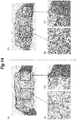
- Figure 14 shows photographs of (A) the base material 2 after the transplant and (D) the artificial bone 1 of Example 2 after the transplant, each having been taken out from the SD rat and dyed.
- (B) and (C) of Figure 14 are enlarged photographs of a central portion (the portion surrounded by a broken line in (A) of Figure 14 ) and a contact portion with the bone of the rat (the portion surrounded by a one-dot chain line in (A) of Figure 14 ), respectively, of the base material 2 after the transplant.
- FIGS. E and (F) of Figure 14 are enlarged photographs of a central portion (the portion surrounded by a broken line in (D) of Figure 14 ) and a contact portion with the bone of the rat (the portion surrounded by a one-dot chain line in (D) of Figure 14 ), respectively, of the artificial bone 1 of Example 2 after the transplant.
- the interior of the pores is primarily a fibrous tissue, and only a small amount of bone formation is observed.
- bone formation was observed in most of the pores.
- a fibrous tissue intervenes at the host bone interface to make a false joint
- (F) of Figure 14 bone fusion can be confirmed at the host bone interface.
- the base material 2 has a substantially rectangular parallelepiped shape, but the present invention is not limited to this, and the base material 2 may be granular, cylindrical, or columnar, for example.
- the film forming step if there is a risk that the carboxylic groups 14 may be formed due to oxygen adsorbed on the inner wall of the chamber 21 or leakage of the chamber 21, it is preferred to keep a state in which the inert gas is flowing for about 5 to 10 minutes before applying voltage to the plate electrodes 22, 23. Thereby, the interior of the chamber 21 is ventilated by the inert gas so that the oxygen concentration is lowered, and therefore, the attachment of the carboxylic groups 14 to the carbonaceous thin film 10 becomes difficult to occur.
- a step of replacing the interior of the chamber 21 with an inert gas (for example, argon) and evacuating the chamber 21 by using the vacuum pump 25 (purge / flush) may be repeated multiple times prior to the film forming step, thereby to lower the oxygen concentration in the interior of the chamber 21.
- an inert gas for example, argon
- the carbonaceous thin film 10 was a polymer film, but the present invention is not limited to this, and the carbonaceous thin film 10 may be any thin film.
- the carbonaceous thin film 10 may be made of graphite carbon or amorphous carbon.
- the carbonaceous thin film 10 containing the functional groups 13 including the amino groups 12 on the surface and in the interior thereof was formed by the chemical vapor deposition method using the plasma containing hydrocarbon, inert gas, and nitrogen, but the present invention is not limited to this method.
- a gas comprising molecules containing nitrogen atoms may be used instead of nitrogen.
- a gas comprising molecules of at least one kind selected from the group consisting of nitrogen, ammonia, and cyclopropylamine By using the gas comprising molecules of at least one kind selected from the group consisting of nitrogen, ammonia, and cyclopropylamine, it is possible to more reliably provide the amino groups 12 on the surface and in the interior of the carbonaceous thin film 10.
- hydrocarbon may be ethane, propane, or ethylene, for example.
- the affinity between the artificial bone 1 and the osteogenic cells was evaluated based on the abundance ratio of nitrogen on the surface and in the interior of the carbonaceous thin film 10 (the abundance ratio of nitrogen in the carbonaceous thin film 10 containing carbon, oxygen, etc.), but the present invention is not limited to this embodiment.
- the evaluation may be performed based on the ratio of the abundance ratio of nitrogen to the abundance ratio of carbon on the surface and in the interior of the carbonaceous thin film 10, and in this case, the abundance ratio of nitrogen on the surface and in the interior of the carbonaceous thin film 10 preferably is at least 10 % of the abundance ratio of carbon.
Landscapes
- Health & Medical Sciences (AREA)
- Chemical & Material Sciences (AREA)
- Transplantation (AREA)
- Epidemiology (AREA)
- Veterinary Medicine (AREA)
- Dermatology (AREA)
- Medicinal Chemistry (AREA)
- Oral & Maxillofacial Surgery (AREA)
- Public Health (AREA)
- General Health & Medical Sciences (AREA)
- Life Sciences & Earth Sciences (AREA)
- Animal Behavior & Ethology (AREA)
- Inorganic Chemistry (AREA)
- Dispersion Chemistry (AREA)
- Engineering & Computer Science (AREA)
- Ceramic Engineering (AREA)
- Materials For Medical Uses (AREA)
Abstract
Description
- The present disclosure relates to an artificial bone containing porous ceramics and a manufacturing method of the artificial bone.
- Some known implant materials such as those for an artificial dental root or the like are provided with a carbonaceous thin film on a surface thereof (for example, Patent Document 1). In the implant material of
Patent Document 1, the carbonaceous thin film contains functional groups containing oxygen (carboxylic groups) and functional groups containing nitrogen (amino groups). By controlling the ratio between the carboxylic groups and the amino groups to a prescribed value, it is possible to suppress differentiation to osteoclasts and to promote differentiation to osteoblasts. - An artificial bone having a porous structure is known (for example, Patent Document 2). In the artificial bone of
Patent Document 2, osteogenic cells get into the pores, whereby the bone tissue formation is done at early stage. -
- [Patent Document 1]
JP2011-45559A - [Patent Document 2]
JP2003-38636A - In the artificial bone of
Patent Document 1, the functional groups are provided on the surface of the carbonaceous thin film, and therefore, there is a problem that the affinity between the artificial bone and the osteogenic cells decreases if the surface of the carbonaceous thin film is eroded by the blood stream or the like. - In view of the foregoing background, an object of the present invention is to provide an artificial bone having a porous structure with an improved affinity to osteogenic cells.
- To achieve the above object, one embodiment of the present invention provides an artificial bone (1) including: a base material (2) containing porous ceramics provided with mutually interconnected pores (6); a carbonaceous thin film (10) formed on an outer surface of the base material and wall surfaces (7) of the pores; and functional groups (13) including amino groups (12) provided on a surface and in an interior of the carbonaceous thin film.
- According to this configuration, since the amino groups are provided on the surface and in the interior of the carbonaceous thin film, the amino groups provided in the interior of the carbonaceous thin film is exposed when the surface of the carbonaceous thin film is eroded by the blood stream or the like, and therefore, it is possible to prevent the decrease in the affinity between the artificial bone and the osteogenic cells due to the erosion of the surface of the carbonaceous thin film. In addition, since the carbonaceous film is formed on the wall surfaces of the pores and the amino groups are formed on the surface and in the interior of the carbonaceous film, the affinity between the artificial bone and the osteogenic cells can be improved in the interior of the base material as well.
- In the above configuration, preferably, an abundance ratio of nitrogen on the surface and in the interior of the carbonaceous thin film is at least 3 %.
- According to this configuration, the carbonaceous thin film may be provided with sufficient amino groups to provide an affinity between the artificial bone and the osteogenic cells.
- In the above configuration, preferably, the abundance ratio of nitrogen on the surface and in the interior of the carbonaceous thin film is at least 10 %.
- According to this configuration, the carbonaceous thin film may be provided with a more sufficient amount of amino groups required to improve the affinity between the artificial bone and the osteogenic cells.
- In the above configuration, preferably, the pores are substantially spherical in shape and have an average diameter greater than or equal to 50 µm and less than or equal to 600 µm, and interpore connecting portions (8) each interconnecting two pores with each other are substantially circular in shape and have an average diameter greater than or equal to 5 µm.
- According to this configuration, it is possible to have the osteogenic cells enter the interior of the base material, and in the manufacturing process, to form the carbonaceous thin film more on the wall surfaces of the pores in the interior of the base material.
- In the above configuration, preferably, at least part of the carbonaceous thin film is formed on the wall surfaces of the pores (7) at a depth of 1 mm or more from the outer surface of the base material.
- According to this configuration, the osteogenic cells can easily enter the interior of the base material, whereby the affinity between the artificial bone and the osteogenic cells can be improved further.
- In the above configuration, preferably, the carbonaceous thin film is formed to reach the wall surfaces of the pores positioned in a central part of the base material.
- According to this configuration, the affinity to the osteogenic cells can be improved over the entirety of the interior of the artificial bone so that the bone tissue formation can be accelerated.
- In the above configuration, preferably, the carbonaceous thin film is a polymer film.
- According to this configuration, , it is possible to form the carbonaceous thin film without requiring a step of implanting high energy ions to harden the carbonaceous thin film, and therefore, the manufacturing process of the artificial bone can be simplified.
- To achieve the above object, one embodiment of the present invention provides a manufacturing method of an artificial bone (1), the method comprising: a step of preparing a base material (2) containing porous ceramics provided with mutually interconnected pores (6); and a step of forming a carbonaceous thin film (10) on an outer surface of the base material and on wall surfaces (7) of the pores by a chemical vapor deposition method using plasma containing hydrocarbon, molecules containing nitrogen atoms, and inert gas.
- According to this configuration, it is possible to form the carbonaceous thin film and at the same time to have amino groups attached to the carbonaceous thin film. Thus, it is possible to provide the amino groups on the surface and in the interior of the carbonaceous thin film. Thereby, even if the surface of the carbonaceous thin film is eroded, a state in which the amino groups are provided on the surface of the carbonaceous thin film is maintained. Therefore, it is possible to prevent the decrease in the affinity between the artificial bone and the osteogenic cells due to the erosion of the surface of the carbonaceous thin film, and the artificial bone having a high affinity to the osteogenic cells can be manufactured more simply.
- According to the foregoing configuration, it is possible to provide an artificial bone having a porous structure with an improved affinity to osteogenic cells.
-
-
Figure 1 shows (A) a schematic diagram of an artificial bone according to an embodiment, (B) a schematic diagram showing a pore portion of the artificial bone, (C) an enlarged view of a surface of the artificial bone, and (D) an enlarged view of the pore portion; -
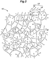
Figure 2 is a schematic diagram of an interior of a carbonaceous thin film; -
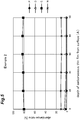
Figure 3 is a schematic diagram of a plasma device used in the manufacture of the artificial bone according to the embodiment; -
Figure 4 is a graph showing abundance ratios of elements (calcium (Ca), phosphorus (P), oxygen (O), carbon (C), nitrogen (N)) on the surface of a base material (Comparative Example) and on the surface of the carbonaceous thin film on the surface of the artificial bone (Examples 1 to 3); -
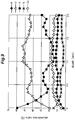
Figure 5 is a graph showing a depth distribution of the abundance ratio of each element on the surface and in the interior of the carbonaceous film on the surface of the artificial bone (Example 2); -
Figure 6 shows photographs showing the results of ALP dyeing experiment (on the fourth day) of three base materials (upper row) and three samples of Example 2 (lower row); -
Figure 7 is a graph showing the number of cell adhesions in a sample of the Comparative Example and the number of cell adhesions in a sample of Example 2 which were counted when two hours elapsed after liquid cell suspension culture medium was dripped into the respective samples; -
Figure 8 includes (A) a graph showing the abundance ratios of the elements insamples 1 to 3, (B) a graph showing the abundance ratios of the elements for the plasma irradiation time of 0 minute, 10 minutes, 30 minutes, and 90 minutes, and (C) a graph showing the dependence of the thickness of the carbonaceous thin film on the plasma irradiation time; -
Figure 9 is a graph showing the depth dependence of the abundance ratios of Ca (calcium), phosphorus (P), oxygen (O), carbon (C), and nitrogen (N) in theartificial bone 1 of Example 2; -
Figure 10 is an explanatory diagram for explaining procedures (A) to (D) for evaluating the affinity between the artificial bone and the osteoblast-like cells; -
Figure 11 shows photographs of dyed sections of (A) the artificial bone of Example 2 and (B) thebase material 2, after continuous culture of osteoblast-like cells; -
Figure 12 is a graph showing ALP activities corresponding to (A) the base material, (B) the artificial bone after autoclave sterilization, and (C) the artificial bone without autoclave sterilization; -
Figure 13 shows X-ray photographs of (A) a side of the base material transplanted in an SD rat, (B) a front of this base material, (C) a side of the artificial bone of Example 2 transplanted in an SD rat, and (D) a front of this artificial bone of Example 2; and -
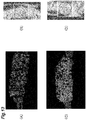
Figure 14 shows (A) a photograph of a dyed section of the base material transplanted in an SD rat, (B) an enlarged view of a part thereof surrounded by a broken line, (C) an enlarged view of a part thereof surrounded by a two-dot chain line, (D) a photograph of a dyed section of the artificial bone of Example 2 transplanted in an SD rat, (E) an enlarged view of a part thereof surrounded by a broken line, and (F) an enlarged view of a part thereof surrounded by a two-dot chain line. - In the following, an artificial bone according to the present invention will be described.
- As shown in (A) of
Figure 1 , anartificial bone 1 includes abase material 2 as a matrix thereof. Thebase material 2 contains porous ceramics as a main component. The porous ceramics is preferably made of hydroxyapatite, β-TCP (β-tricalcium phosphate) or a mixture of hydroxyapatite and β-TCP. - As shown in (B) of
Figure 1 , in the present embodiment, thebase material 2 has a substantially rectangular parallelepiped shape. Thebase material 2 hasmultiple pores 6 and forms a porous structure. Eachpore 6 is defined by apore wall surface 7 and has a substantially spherical shape. The average diameter of thepores 6 is greater than or equal to 50 µm and less than or equal to 600 µm, and preferably, greater than or equal to 80 µm and less than or equal to 300 µm. In the present embodiment, the average diameter of thepores 6 is 150 µm. Thepores 6 are interconnected with each other viainterpore connecting portions 8. Eachinterpore connecting portion 8 is substantially circular in shape. The average diameter of theinterpore connecting portions 8 is greater than or equal to 5 µm, and more preferably, greater than or equal to 10 µm and less than or equal to 100 µm. In the present embodiment, the average diameter of theinterpore connecting portions 8 is 40 µm. Note that the average diameter of thepores 6 is calculated by polishing thebase material 2 embedded in resin, observing it with an electron microscope or the like to select substantiallyspherical pores 6 by means of image analysis, and measuring the pore area of them. Preferably, the pore area is calculated by measuring the pore areas of at least 300pores 6 and averaging them. The pore area obtained here should preferably be three-dimensionally corrected because it is measured in a section by a plane passing a part of a substantiallyspherical pore 6 which may not coincide with the diameter of thepore 6. The average diameter of theinterpore connecting portions 8 is preferably measured by using the well-known mercury intrusion porosimetry. In a case where the mercury intrusion porosimetry cannot be applied, one may observe the cross section of thebase material 2 with an electron microscope, measure the diameters of theinterpore connecting portions 8, and calculate the average thereof as the average diameter. Also preferably, the porosity of thebase material 2 is greater than or equal to 60 % and less than or equal to 90 %, and the pore volume in which living body tissue can enter occupies 50 %. Note that the porosity is preferably calculated by preparing a sintered body having the same composition as thebase material 2, obtaining the true density (ρ*) of the sintered body by using a true density meter, obtaining the density (p) of thebase material 2 by dividing its weight by the volume obtained from the dimensions of thebase material 2, and calculating the porosity as 1 - ρ/ρ*. - As shown in (C) and (D) of
Figure 1 , the outer surface of thebase material 2 and the pore wall surfaces 7 are each provided with a carbonaceousthin film 10. At least part of the carbonaceousthin film 10 is formed to extend from the outer surface of the base material 2 (part of the surface defining the outer contour) to the pore wall surfaces 7 positioned at a prescribed depth (adsorption depth). The adsorption depth is at least 0.3 mm, and preferably is at least 1 mm. More preferably, the adsorption depth is greater than or equal to 2 mm. In the present embodiment, the adsorption depth is about 2 mm. - Also, the carbonaceous
thin film 10 is preferably formed to reach the wall surfaces of thepores 6 positioned in a central part of thebase material 2. Thereby, the carbonaceousthin film 10 is formed on the wall surfaces of the pores 6 (namely, the pore wall surfaces 7) positioned in the deepest part from the outer surface of thebase material 2. - The depth here refers to a distance from a reference point positioned on an end (outer surface) of a sample. The reference point is determined by obtaining an approximate position of the end of the sample by using a camera, measuring XPS randomly at multiple points in the vicinity thereof, and thereafter determining, from among the multiple points, a point where the maximum XPS signal was obtained.
- The carbonaceous
thin film 10 preferably is a hydrocarbon polymer film having a thickness greater than or equal to 0.1 µm and less than or equal to 3.0 µm. The carbonaceousthin film 10 may be a diamond-like carbon (DLC) film. - The carbonaceous
thin film 10 is provided, on a surface and in an interior (seeFigure 2 ) thereof, with functional groups 13 (see the portion surrounded by a two-dot chain line inFigure 2 ) including amino groups 12 (primary amine -NH2, secondary amine -NH, or tertiary amine -N). Theamino groups 12 are provided substantially uniformly in the interior of the carbonaceousthin film 10. - Note that in the present description, the primary amines, secondary amines, and tertiary amines are collectively referred to as amino groups. (More precisely, the
amino groups 12 here refer to monovalent functional groups (-NH2, -NHR, -NRR') (R is a hydrocarbon residue) obtained by removing hydrogen from ammonia, primary amines, or secondary amines. In the present description, a monovalent functional group (-NH2) obtained by removing hydrogen from ammonia may be referred to as a primary amine, a monovalent functional group (-NH) obtained by removing hydrogen from a primary amine may be referred to as a secondary amine, and a monovalent functional group (-N) obtained by removing hydrogen from a secondary amine may be referred to as a tertiary amine, as necessary.) - The
functional groups 13 may include carboxylic groups 14 (-COOH), where a carboxylic group is a functional group containing oxygen. To provide the carbonaceousthin film 10 with a sufficient amount ofamino groups 12 required to improve the affinity between theartificial bone 1 and the osteogenic cells, the abundance ratio (atomic percent) of nitrogen on the surface and in the interior of the carbonaceous thin film 10 (the abundance ratio of nitrogen in the carbonaceousthin film 10 containing carbon, oxygen, etc.) is preferably greater than or equal to 3 %, and more preferably is greater than or equal to 10 %. Specifically, the abundance ratio of each element is determined based on the energy spectrum of photoelectrons obtained by using X-ray photoelectron spectroscopy (XPS), and corresponds to the ratio of the atoms of each element to the all atoms present in a sphere which has a center at the target point and whose diameter coincides with the spot diameter (about 2 mm to 1 cm) of the X-ray used in the XPS. - Next, a manufacturing method of the
artificial bone 1 will be described. In the manufacture of theartificial bone 1, aplasma device 20 schematically shown inFigure 3 is used. Theplasma device 20 includes a vacuum chamber 21 (hereinafter, chamber), in which a pair ofparallel plate electrodes lower plate electrode 22 is grounded and theupper plate electrode 23 is connected with avoltage generator 24. Thechamber 21 is connected with avacuum pump 25 for evacuating the interior of thechamber 21. - When manufacturing the
artificial bone 1, first, thebase material 2 is placed on thelower plate electrode 22, and thechamber 21 is vacuum-evacuated by thevacuum pump 25 to prepare for film formation (preparation step). - Next, while the interior of the
chamber 21 is being evacuated, nitrogen, a hydrocarbon-containing gas, and an inert gas are introduced into the interior of thechamber 21 at respective constant flow rates. As the hydrocarbon-containing gas, methane gas is preferably used. In this way, by using hydrocarbon having a low molecular weight, it is possible to lower the molecular weight of hydrocarbon, and therefore, hydrocarbon can enter deeper from the outer surface of thebase material 2 compared to when other hydrocarbon is used. As the inert gas, it is preferred to use helium gas or argon gas. - Next, a prescribed voltage is applied to the
upper plate electrode 23 by thevoltage generator 24 to generate plasma between theplate electrodes - When the voltage is applied to the
upper plate electrode 23, part of the nitrogen molecules and the hydrocarbon-containing gas in thechamber 21 are dissociated to become chemically active radicals. Further, due to collision with electrons accelerated by the electric field generated between theplate electrodes base material 2 and the pore wall surfaces 7 up to a prescribed depth from the outer surface of thebase material 2 and form the carbonaceous thin film 10 (film forming step). Namely, in the film forming step, the carbonaceousthin film 10 is formed by so-called plasma CVD, which is one of chemical vapor deposition methods, using the plasma containing nitrogen, hydrocarbon (methane), and inert gas (helium or argon). - In the film forming step, since nitrogen is introduced at a constant flow rate, the carbonaceous
thin film 10 is formed while being terminated by the amino groups 12. Thereby, theamino groups 12 are distributed substantially uniformly on the surface and in the interior of the carbonaceousthin film 10. - By continuing the film forming step for a prescribed time, the
amino groups 12 are provided on the surface and in the interior of the carbonaceousthin film 10 formed on the outer surface of thebase material 2 and the pore wall surfaces 7 up to a depth greater than or equal to 0.3 mm, more preferably greater than or equal to 1 mm, from the outer surface. - In this way, by providing the
amino groups 12 on the surface and in the interior of the carbonaceousthin film 10 formed on the pore wall surfaces 7, the affinity between the pore wall surfaces 7 and the osteogenic cells is improved. Thereby, the osteogenic cells can enter the interior of thebase material 2 easily, and the osteogenic cells are easily attached to theartificial bone 1 in the interior of the pores also. - The carbonaceous
thin film 10 is preferably formed to reach the wall surfaces of thepores 6 positioned in the central part of thebase material 2. More specifically, it is preferred that the carbonaceousthin film 10 reaches the wall surfaces of the pores 6 (the pore wall surfaces 7) positioned in the deepest part from the outer surface of thebase material 2. Thereby, the carbonaceousthin film 10 is formed in thepores 6 formed in the interior of theartificial bone 1 at any depth. Therefore, even if theartificial bone 1 is eroded by the blood stream or the like, the affinity to the cells can be maintained, and the affinity to the osteogenic cells can be improved over the entire interior of theartificial bone 1. - Also, in the film forming step, the carbonaceous
thin film 10 may be formed as a polymer film, and does not necessarily have to be formed as a diamond-like carbon film. Thereby, the carbonaceousthin film 10 can be formed by a more simple process without requiring a step of implanting high energy ions to harden the carbonaceousthin film 10 as when forming the diamond-like carbon. - After the film forming step is completed, the interior of the
chamber 21 is evacuated. Thereafter, nitrogen, atmosphere or the like is introduced into the interior of thechamber 21 to vent thechamber 21, and thebase material 2 is taken out (take-out step), whereby the manufacture of theartificial bone 1 is completed. - Next, effects of the
artificial bone 1 according to the present invention will be described. By performing the above-described manufacturing process, anartificial bone 1 obtained by subjecting abase material 2 consisting of a porous hydroxyapatite to plasma irradiation for 30 minutes with introduced methane, nitrogen, and argon (Example 1), anartificial bone 1 obtained by subjecting asimilar base material 2 to plasma irradiation for 30 minutes with introduced methane, nitrogen, and helium (Example 2), and anartificial bone 1 obtained by subjecting asimilar base material 2 to plasma irradiation for 20 minutes with introduced methane, nitrogen, and helium (Example 3) were prepared. Note that in in Examples 1 to 3, the flow rate of methane, the flow rate of argon, and the flow rate of helium were set to be the same. The flow rate of the nitrogen gas in Example 1 was the same as the flow rate of the other gases, while in the film forming step in Examples 2 and 3, the flow rate of the nitrogen gas was doubled compared to the case of Example 1. In Example 2, the pressure in the chamber during plasma irradiation was set to 70 % of that of Examples 1 and 3. Further, in the manufacture of theartificial bones 1 of Examples 1 to 3,cylindrical base materials 2 each having a radius of 5 mm and a thickness of 2 mm were used. - Subsequently, the abundance ratios (%) of calcium (Ca), phosphorus (P), oxygen (O), carbon (C), and nitrogen (N) on the surface of the base material 2 (Comparative Example) and on the surface of the carbonaceous
thin film 10 provided on the outer surface of each of Examples 1 to 3 were measured by X-ray photoelectron spectroscopy (XPS), as shown inFigure 4 . More specifically, by using ESCA850M, which is an XPS device made by SHIMADZU CORPORATION, MgKa ray (1253.6 eV) was irradiate onto the surface of each sample, and an energy spectrum of generated photoelectrons was measured to calculate the abundance ratio (%) of each element. Note that since hydrogen cannot be detected by XPS, the abundance ratio of hydrogen is ignored inFigure 4 . Also, with ES-CA850M, the spot diameter of X-ray was about 1 cm. - As shown in
Figure 4 , the abundance ratios of phosphorus and oxygen are reduced in each of Examples 1 to 3 compared to Comparative Example. This indicates that since the surface of thebase material 2 of each of Examples 1 to 3 was covered by the carbonaceousthin film 10, fewer photoelectrons were released from the atoms constituting the base material 2 (hydroxyapatite) serving as a foundation. Also, in each of Examples 1 to 3, the abundance ratios of carbon and nitrogen were increased compared to Comparative Example. This indicates that the carbonaceousthin film 10 formed on the surface of each of Examples 1 to 3 is provided with theamino groups 12. - In Example 2, Example 2, and Example 3, since the abundance ratio of oxygen is low compared to the abundance ratio of nitrogen, it is inferred that on the surface of the carbonaceous
thin film 10, thecarboxylic groups 14 are smaller in number compared to the amino groups 12. - Since nitrogen is introduced during the formation of the carbonaceous
thin film 10, it can be expected that nitrogen atoms constituting theamino groups 12 are present not only on the surface of the carbonaceousthin film 10 but also in the interior of the same. To confirm this, while etching the carbonaceousthin film 10 of Example 2 with an argon ion beam, the abundance ratios of calcium (Ca), phosphorus (P), oxygen (O), carbon (C), and nitrogen (N) were measured by using ESCA850M of SHIMADZU CORPORATION.Figure 5 shows a graph showing the etching depth dependence of the abundance ratio of each element measured; namely, a depth distribution of the abundance ratio of each element on the surface and in the interior of the carbonaceousthin film 10 provided on the outer surface of the artificial bone 1 (Example 2). FromFigure 5 , it can be seen that the abundance ratio of nitrogen is substantially constant from the surface of the carbonaceousthin film 10 to the depth of 100 angstroms (0.01 µm). This confirms that theamino groups 12 are provided on the surface and in the interior of the carbonaceousthin film 10. Thus, by using plasma containing nitrogen, hydrocarbon, and argon, it is possible to provide theamino groups 12 on the surface and in the interior of the carbonaceousthin film 10. Thereby, even if the surface of the carbonaceousthin film 10 is erode by the blood stream or the like, theamino groups 12 are exposed on the surface of the carbonaceousthin film 10 so that the state in which theamino groups 12 are provided on the surface of the carbonaceousthin film 10 is maintained, whereby the affinity between theartificial bone 1 and the osteogenic cells can be maintained. - In the present embodiment, since the flow rate of nitrogen is maintained constant during the film formation, the
amino groups 12 are distribute substantially uniformly on the surface and in the interior of the carbonaceousthin film 10. As a result, regardless of an amount of erosion of the carbonaceousthin film 10, the affinity between theartificial bone 1 and the osteogenic cells can be maintained substantially constant. - To provide an affinity between the
artificial bone 1 and the osteogenic cells, the abundance ratio of nitrogen on the surface and in the interior of the carbonaceousthin film 10 is preferably greater than or equal to 3 %, and more preferably is greater than or equal to 10 %. Thereby, the carbonaceousthin film 10 can be provided with sufficientamino groups 12 to provide an affinity between theartificial bone 1 and the osteogenic cells. - In the present embodiment, the abundance ratio of nitrogen is 10.2 % in Example 1, 17 % in Example 2, and 13 % in Example 3. Therefore, the affinity between the
artificial bone 1 and the osteogenic cells is improved. In Examples 1 to 3, since the abundance ratio of nitrogen is greater than or equal to 10 %, the ratio of the abundance ratio of nitrogen to the abundance ratio of carbon also is greater than or equal to 10 %. - Next, to confirm the effects of the provision of the carbonaceous
thin film 10, an alkaline phosphatase (ALP) dyeing experiment was conducted on three samples of Comparative Example and three samples of Example 2 by using mouse osteoblast-like cells (MC3T3-E1 cell line). As shown inFigure 6 , in the ALP dyeing experiment on day 4, almost no dyeing by ALP dyeing is observed in the case of Comparative Example shown in the upper row. On the other hand, ALP dyeing is observed in each of the three samples of Example 2 shown in the lower row. Thus, it was confirmed that the provision of the carbonaceousthin film 10 promoted the proliferation and differentiation of osteoblasts and improved the affinity to the osteogenic cells. - Further, to confirm the effects of the provision of the carbonaceous
thin film 10, an experiment was conducted to evaluate the cell adhesion by using the osteoblastic cell line, MC3T3-E1. Liquid cell suspension culture was dripped into the respective samples of Example 2 and the Comparative Example, and two hours after that, the number of cells that have adhered to each sample (the number of adhering cells) was counted. As shown inFigure 7 , the number of adhering cells is significantly increased in the sample of Example 2 compared to the sample of the Comparative Example, and this confirms the cell adhesion promoting effect of the provision of the carbonaceousthin film 10. - To confirm that the
amino groups 12 are formed on the carbonaceousthin film 10 due to the introduction of nitrogen during the film formation, three samples (sample 1,sample 2, and sample 3) were prepared by conducting the film formation with only the nitrogen flow rate changed. Note thatsample 1 was prepared by using a silicon wafer instead of thebase material 2 and helium instead of argon, but by conducting the plasma irradiation for 30 minutes under the otherwise same plasma conditions as in Example 1.Sample 2 was prepared by subjecting a silicon wafer to the plasma irradiation for 30 minutes under the same plasma conditions as in the preparation ofsample 1 except that only the flow rate of nitrogen was doubled.Sample 3 was prepared by subjecting a silicon wafer to the plasma irradiation for 30 minutes under the same plasma conditions as in the preparation ofsample 1 except that only the flow rate of nitrogen was changed to zero. Note that though each ofsample 1 to sample 3 was prepared by irradiating plasma onto a silicon wafer, in the case where the silicon wafer is used also, the carbonaceousthin film 10 having a composition similar to that obtained when thebase material 2 is used is formed. After the film formation, XPS was measured for the carbonaceousthin film 10 formed on the surface of each ofsamples 1 to 3. Note that KRATOS AXIS-165X made by SHIMADZU CORPORATION was used in the measurement of XPS. With KRATOS AXIS-165X, the spot diameter of X-ray was about 2 mm. - (A) of
Figure 8 shows the abundance ratios (%) of carbon (C), nitrogen (N), oxygen (O), and silicon (Si) ofsamples 1 to 3 obtained based on C (carbon) 1s spectrum, N (nitrogen) 1s spectrum, O (oxygen) 1s spectrum, and Si (silicon) 2p spectrum of XPS. It can be confirmed that the abundance ratio of nitrogen is substantially 0 % insample 3, while the abundance ratio of nitrogen is greater than or equal to 10 % insamples - Next, to further confirm that the
amino groups 12 are provided in the interior of the carbonaceousthin film 10, plasma irradiation was performed on a silicon wafer under the plasma conditions used at the time of preparation ofsample 1 but with varying plasma irradiation times. Thereafter, XPS was measured by using KRATOS AXIS-165X to obtain the abundance ratio of each element. (B) ofFigure 8 shows the abundance ratios (%) of carbon (C), nitrogen (N), oxygen (O), and silicon (Si) for the plasma irradiation times of 0 minute (namely, no plasma irradiation), 10 minutes, 30 minutes, and 90 minutes. Note that in the calculation of the abundance ratios, C (carbon) 1s spectrum, N (nitrogen) 1s spectrum, O (oxygen) 1s spectrum, and Si (silicon) 2p spectrum wee used as in (A) ofFigure 8 . As shown in (B) ofFigure 8 , the abundance ratio of nitrogen is about 12 % and constant, and thus, it can be seen that the abundance ratio of nitrogen does not depend on the plasma irradiation time. As shown in (C) ofFigure 8 , the thickness of the carbonaceousthin film 10 monotonically increases with the plasma irradiation time, and thus, it can be confirmed that in the interior of the carbonaceousthin film 10 also, nitrogen, namely, theamino groups 12 are present uniformly. - Next, the depth dependence of the abundance ratios of Ca (calcium), phosphorus (P), oxygen (O), carbon (C), and nitrogen (N) of the
artificial bone 1 of Example 2 was evaluated, and the graph shown inFigure 9 was obtained. Here, the abundance ratios were determined based on the energy spectrum of photoelectrons obtained by using X-ray photoelectron spectroscopy (XPS), and the measurement was performed by using PHI Quantera SXM. Note that a reference point, which is a reference of the depth depth (namely, a point where the depth is zero), was determined by obtaining an approximate position of the upper end of theartificial bone 1 of Example 2 to be measured by using a camera equipped to Quantera SXM, measuring XPS randomly at multiple points in the vicinity thereof, and thereafter determining, from among the multiple points, a point where the maximum XPS signal was obtained. - As shown in
Figure 9 , the abundance ratios of carbon and nitrogen are the highest on the top surface and decrease with the depth in the depth range of 0 to 0.5 mm. It can be confirmed that thereafter, in the vicinity of the bottom surface (∼2 mm), the abundance ratios of carbon and nitrogen have a tendency to slightly increase. Since the abundance ratio of nitrogen decreases with the depth in the depth range of 0 to 0.5 mm and the abundance ratio of nitrogen is about 0.5 % when the film forming step is not performed, it could be confirmed that as a result of the film forming step, nitrogen was present to the depth of 0.5 to 1.0 mm. Thus, it can be said that in theartificial bone 1 of Example 2, theamino groups 12 were formed to the depth of 0.5 to 1.0 mm. - Subsequently, the affinity between the
artificial bone 1 and the osteoblast-like cells, which are osteogenic cells, was evaluated. First, theartificial bone 1 of Example 2 after one month from manufacture was subjected to autoclave sterilization. A liquid cell suspension containing the osteoblastic cell line, MC3T3-E1 (3×10⁵ cells / 35 µl) was dripped onto the top surface of theartificial bone 1 after one day from the sterilization (see (A) ofFigure 10 ), and adhesion was caused to occur for about one hour (see (B) ofFigure 10 ). After adhesion, theartificial bone 1 was placed in a petri dish, to which a culture medium was added, and continuous culture was performed for about two hours (see (C) ofFigure 10 ). Thereafter, theartificial bone 1 was taken out and dyed with crystal violet. Then, the dyedartificial bone 1 was cut in the middle and the image of the section shown in (A) ofFigure 11 was obtained. Similar processing was performed on thebase material 2, and the image of the section shown in (B) ofFigure 11 was obtained. Compared to (A) ofFigure 11 , it can be confirmed that in (B) ofFigure 11 , the interior is dyed and thus the osteogenic cells can enter theartificial bone 1 easily. - Further, after performing the process shown in
Figure 10 on each of thebase material 2, theartificial bone 1 of Example 2 after autoclave sterilization, and theartificial bone 1 of Example 2 without autoclave sterilization, ALP activity was measured.Figure 12 shows ALP activity values respectively measured for (A) thebase material 2, (B) theartificial bone 1 of Example 2 after autoclave sterilization, and (C) theartificial bone 1 of Example 2 without autoclave sterilization. By comparing (A) and (C) ofFigure 12 , it can be confirmed that theartificial bone 1 has a higher affinity to the osteogenic cells compared to thebase material 2. Also, comparison between (B) and (C) ofFigure 12 shows that the affinity between theartificial bone 1 and the osteogenic cells does not decrease considerably after the autoclave sterilization treatment, which indicates that the osteogenic cells have entered the interior of theartificial bone 1. - Further, to evaluate the affinity between the
artificial bone 1 and the osteogenic cells, each of thebase material 2 and theartificial bone 1 of Example 2 was transplanted to a bone of a 10 week old male SD rat serving as a host after autoclave sterilization, and was X-rayed six weeks from the transplant. (A) and (B) ofFigure 13 are X-ray photographs of thebase material 2, and (C) and (D) ofFigure 13 are X-ray photographs of theartificial bone 1 of Example 2. From (A) and (C) ofFigure 13 and portions of (B) and (B) ofFigure 13 surrounded by broken lines, it can be confirmed that since the osteogenic cells have entered the interior, the interior is white in theartificial bone 1 of Example 2 compared to thebase material 2. Thus, it can be confirmed that compared to thebase material 2, the osteogenic cells were easy to enter in theartificial bone 1. -
Figure 14 shows photographs of (A) thebase material 2 after the transplant and (D) theartificial bone 1 of Example 2 after the transplant, each having been taken out from the SD rat and dyed. (B) and (C) ofFigure 14 are enlarged photographs of a central portion (the portion surrounded by a broken line in (A) ofFigure 14 ) and a contact portion with the bone of the rat (the portion surrounded by a one-dot chain line in (A) ofFigure 14 ), respectively, of thebase material 2 after the transplant. (E) and (F) ofFigure 14 are enlarged photographs of a central portion (the portion surrounded by a broken line in (D) ofFigure 14 ) and a contact portion with the bone of the rat (the portion surrounded by a one-dot chain line in (D) ofFigure 14 ), respectively, of theartificial bone 1 of Example 2 after the transplant. In (B) ofFigure 14 , the interior of the pores is primarily a fibrous tissue, and only a small amount of bone formation is observed. In contrast, in (E) ofFigure 14 , bone formation was observed in most of the pores. Also, in (C) ofFigure 14 , a fibrous tissue intervenes at the host bone interface to make a false joint, while in (F) ofFigure 14 , bone fusion can be confirmed at the host bone interface. - Concrete embodiments have been described in the foregoing, but the present invention is not limited by the above-described embodiments and may be modified or altered in various ways. In the above-described embodiment, the
base material 2 has a substantially rectangular parallelepiped shape, but the present invention is not limited to this, and thebase material 2 may be granular, cylindrical, or columnar, for example. - In the film forming step, if there is a risk that the
carboxylic groups 14 may be formed due to oxygen adsorbed on the inner wall of thechamber 21 or leakage of thechamber 21, it is preferred to keep a state in which the inert gas is flowing for about 5 to 10 minutes before applying voltage to theplate electrodes chamber 21 is ventilated by the inert gas so that the oxygen concentration is lowered, and therefore, the attachment of thecarboxylic groups 14 to the carbonaceousthin film 10 becomes difficult to occur. Also, a step of replacing the interior of thechamber 21 with an inert gas (for example, argon) and evacuating thechamber 21 by using the vacuum pump 25 (purge / flush) may be repeated multiple times prior to the film forming step, thereby to lower the oxygen concentration in the interior of thechamber 21. - In the above-described embodiment, the carbonaceous
thin film 10 was a polymer film, but the present invention is not limited to this, and the carbonaceousthin film 10 may be any thin film. For example, the carbonaceousthin film 10 may be made of graphite carbon or amorphous carbon. - In the above-described embodiment, the carbonaceous
thin film 10 containing thefunctional groups 13 including theamino groups 12 on the surface and in the interior thereof was formed by the chemical vapor deposition method using the plasma containing hydrocarbon, inert gas, and nitrogen, but the present invention is not limited to this method. For example, instead of nitrogen, a gas comprising molecules containing nitrogen atoms may be used. It is also possible to use a gas comprising molecules of at least one kind selected from the group consisting of nitrogen, ammonia, and cyclopropylamine. By using the gas comprising molecules of at least one kind selected from the group consisting of nitrogen, ammonia, and cyclopropylamine, it is possible to more reliably provide theamino groups 12 on the surface and in the interior of the carbonaceousthin film 10. - In the above-described embodiment, methane was used as hydrocarbon, but the present invention is not limited to this embodiment and hydrocarbon may be ethane, propane, or ethylene, for example.
- In the above-described embodiment, the affinity between the
artificial bone 1 and the osteogenic cells was evaluated based on the abundance ratio of nitrogen on the surface and in the interior of the carbonaceous thin film 10 (the abundance ratio of nitrogen in the carbonaceousthin film 10 containing carbon, oxygen, etc.), but the present invention is not limited to this embodiment. For example, the evaluation may be performed based on the ratio of the abundance ratio of nitrogen to the abundance ratio of carbon on the surface and in the interior of the carbonaceousthin film 10, and in this case, the abundance ratio of nitrogen on the surface and in the interior of the carbonaceousthin film 10 preferably is at least 10 % of the abundance ratio of carbon. -
- 1:
- artificial bone
- 2:
- base material
- 6:
- pore
- 7:
- pore wall surface
- 8:
- interpore connecting portion
- 10:
- carbonaceous thin film
- 12:
- amino group
- 13:
- functional group
Claims (8)
- An artificial bone comprising:a base material containing porous ceramics provided with mutually interconnected pores;a carbonaceous thin film formed on an outer surface of the base material and wall surfaces of the pores; andfunctional groups including amino groups provided on a surface and in an interior of the carbonaceous thin film.
- The artificial bone according to claim 1, wherein an abundance ratio of nitrogen on the surface and in the interior of the carbonaceous thin film is at least 3 %.
- The artificial bone according to claim 2, wherein the abundance ratio of nitrogen on the surface and in the interior of the carbonaceous thin film is at least 10 %.
- The artificial bone according to any one of claims 1 to 3, wherein the pores are substantially spherical in shape and have an average diameter greater than or equal to 50 µm and less than or equal to 600 µm, and
interpore connecting portions each interconnecting two pores with each other are substantially circular in shape and have an average diameter greater than or equal to 5 µm. - The artificial bone according to any one of claims 1 to 4, wherein the carbonaceous thin film is formed to reach the wall surfaces of the pores at a depth of 1 mm or more from the outer surface of the base material.
- The artificial bone according to any one of claims 1 to 5, wherein the carbonaceous thin film is formed to reach the wall surfaces of the pores positioned in a central part of the base material.
- The artificial bone according to any one of claims 1 to 6, wherein the carbonaceous thin film is a polymer film.
- A manufacturing method of an artificial bone, the method comprising:a step of preparing a base material containing porous ceramics provided with mutually interconnected pores; anda step of forming a carbonaceous thin film on an outer surface of the base material and on wall surfaces of the pores by a chemical vapor deposition method using plasma containing hydrocarbon, molecules containing nitrogen atoms, and an inert gas.
Applications Claiming Priority (2)
| Application Number | Priority Date | Filing Date | Title |
|---|---|---|---|
| JP2018150717 | 2018-08-09 | ||
| PCT/JP2019/030787 WO2020031988A1 (en) | 2018-08-09 | 2019-08-05 | Artificial bone and artificial bone production method |
Publications (2)
| Publication Number | Publication Date |
|---|---|
| EP3834854A1 true EP3834854A1 (en) | 2021-06-16 |
| EP3834854A4 EP3834854A4 (en) | 2022-05-11 |
Family
ID=69414834
Family Applications (1)
| Application Number | Title | Priority Date | Filing Date |
|---|---|---|---|
| EP19846595.7A Withdrawn EP3834854A4 (en) | 2018-08-09 | 2019-08-05 | ARTIFICIAL BONE AND METHOD FOR PRODUCING ARTIFICIAL BONE |
Country Status (4)
| Country | Link |
|---|---|
| US (1) | US12186456B2 (en) |
| EP (1) | EP3834854A4 (en) |
| JP (1) | JP7201971B2 (en) |
| WO (1) | WO2020031988A1 (en) |
Family Cites Families (9)
| Publication number | Priority date | Publication date | Assignee | Title |
|---|---|---|---|---|
| US6713420B2 (en) | 2000-10-13 | 2004-03-30 | Toshiba Ceramics Co., Ltd. | Porous ceramics body for in vivo or in vitro use |
| JP3470759B2 (en) | 2000-10-13 | 2003-11-25 | 東芝セラミックス株式会社 | Ceramic porous material for living body |
| ES2424614T3 (en) * | 2001-05-01 | 2013-10-07 | Amedica Corporation | Radiolucent bone graft |
| JP2004159971A (en) * | 2002-11-14 | 2004-06-10 | Hideki Yoshikawa | Bone forming member and method of manufacturing the same |
| GB2462883A (en) * | 2008-08-29 | 2010-03-03 | Univ Sheffield Hallam | Antimicrobial sol-gel coating |
| JP5403542B2 (en) | 2009-08-27 | 2014-01-29 | 国立大学法人広島大学 | Implant manufacturing method |
| EP2397125A1 (en) * | 2010-06-15 | 2011-12-21 | Histocell, S.L. | Antioxidant composition |
| JP2012012329A (en) | 2010-06-30 | 2012-01-19 | Tokai Univ | Implant material |
| JP6029865B2 (en) * | 2012-06-25 | 2016-11-24 | 国立大学法人広島大学 | Implant, method for producing the same, and method for controlling bone metabolism |
-
2019
- 2019-08-05 WO PCT/JP2019/030787 patent/WO2020031988A1/en not_active Ceased
- 2019-08-05 EP EP19846595.7A patent/EP3834854A4/en not_active Withdrawn
- 2019-08-05 JP JP2020535774A patent/JP7201971B2/en active Active
- 2019-08-05 US US17/266,382 patent/US12186456B2/en active Active
Also Published As
| Publication number | Publication date |
|---|---|
| JP7201971B2 (en) | 2023-01-11 |
| US12186456B2 (en) | 2025-01-07 |
| US20210290827A1 (en) | 2021-09-23 |
| WO2020031988A1 (en) | 2020-02-13 |
| JPWO2020031988A1 (en) | 2021-08-10 |
| EP3834854A4 (en) | 2022-05-11 |
Similar Documents
| Publication | Publication Date | Title |
|---|---|---|
| Wang et al. | Enhanced osteoblast responses to poly ether ether ketone surface modified by water plasma immersion ion implantation | |
| US10117966B2 (en) | Method for producing nanosurfaces with nano, micron, and/or submicron structures on a polymer | |
| Losic et al. | Surface modification of nanoporous alumina membranes by plasma polymerization | |
| Cheng et al. | Comparative study of different nitrogen-containing plasma modifications applied on 3D porous PCL scaffolds and 2D PCL films | |
| Raikar et al. | Surface characterization of titanium implants | |
| KR101483846B1 (en) | A tube with modified inner wall surface and preparation method thereof | |
| EP2221274B1 (en) | Carbonaceous thin film and manufacturing method for same | |
| US9799488B2 (en) | Method and apparatus for neutral beam processing based on gas cluster ion beam technology | |
| KR20160029985A (en) | A method for generating plasma uniformly on dielectric material | |
| Battistoni et al. | Surface characterization of biocompatible hydroxyapatite coatings | |
| Pandiyaraj et al. | Non-thermal plasma jet-assisted development of phosphorus-containing functional coatings on 3D-printed PCL scaffolds intended for bone tissue engineering | |
| US12186456B2 (en) | Artificial bone and manufacturing method of artificial bone | |
| KR20130122611A (en) | Implant material | |
| JP5914464B2 (en) | Method for improving bioactive properties of surfaces and objects having improved surfaces thereby | |
| da Silva et al. | Osteoblastlike cell adhesion on titanium surfaces modified by plasma nitriding. | |
| JP2007258154A (en) | Ion implantation device | |
| Neto et al. | In vitro study of cell behaviour on plasma surface modified titanium | |
| JP2009279268A (en) | Antithrombogenic material | |
| Giljean et al. | Statistical approach of chemistry and topography effect on human osteoblast adhesion | |
| JP2006230639A (en) | Catheters with modified living body contact parts | |
| L Zhao et al. | In vitro cell adhesion and hemocompatibility of carbon nanotubes with CNx coating | |
| Nichols et al. | Bioevaluation of plasma polymerized films in skeletal muscle | |
| WO2019154762A1 (en) | Medical implants comprising anti-infective surfaces | |
| KR20200116189A (en) | Method for preparation of bioresorbable metal-based complex matrix with enhanced biodoegradability using selective plasma etching | |
| Starikov et al. | Diamond biocompatible coatings for medical implants |
Legal Events
| Date | Code | Title | Description |
|---|---|---|---|
| STAA | Information on the status of an ep patent application or granted ep patent |
Free format text: STATUS: THE INTERNATIONAL PUBLICATION HAS BEEN MADE |
|
| PUAI | Public reference made under article 153(3) epc to a published international application that has entered the european phase |
Free format text: ORIGINAL CODE: 0009012 |
|
| STAA | Information on the status of an ep patent application or granted ep patent |
Free format text: STATUS: REQUEST FOR EXAMINATION WAS MADE |
|
| 17P | Request for examination filed |
Effective date: 20210305 |
|
| AK | Designated contracting states |
Kind code of ref document: A1 Designated state(s): AL AT BE BG CH CY CZ DE DK EE ES FI FR GB GR HR HU IE IS IT LI LT LU LV MC MK MT NL NO PL PT RO RS SE SI SK SM TR |
|
| DAV | Request for validation of the european patent (deleted) | ||
| DAX | Request for extension of the european patent (deleted) | ||
| A4 | Supplementary search report drawn up and despatched |
Effective date: 20220413 |
|
| RIC1 | Information provided on ipc code assigned before grant |
Ipc: A61L 27/12 20060101ALI20220407BHEP Ipc: A61L 27/56 20060101ALI20220407BHEP Ipc: A61L 27/30 20060101AFI20220407BHEP |
|
| REG | Reference to a national code |
Ref country code: DE Ref legal event code: R079 Free format text: PREVIOUS MAIN CLASS: A61L0027100000 Ipc: A61L0027300000 |
|
| GRAP | Despatch of communication of intention to grant a patent |
Free format text: ORIGINAL CODE: EPIDOSNIGR1 |
|
| RIC1 | Information provided on ipc code assigned before grant |
Ipc: A61L 27/12 20060101ALI20231019BHEP Ipc: A61L 27/56 20060101ALI20231019BHEP Ipc: A61L 27/30 20060101AFI20231019BHEP |
|
| STAA | Information on the status of an ep patent application or granted ep patent |
Free format text: STATUS: GRANT OF PATENT IS INTENDED |
|
| INTG | Intention to grant announced |
Effective date: 20231123 |
|
| STAA | Information on the status of an ep patent application or granted ep patent |
Free format text: STATUS: THE APPLICATION IS DEEMED TO BE WITHDRAWN |
|
| 18D | Application deemed to be withdrawn |
Effective date: 20240326 |