EP3834769A1 - Portable device for robotic intraoral preparation of abutment teeth - Google Patents
Portable device for robotic intraoral preparation of abutment teeth Download PDFInfo
- Publication number
- EP3834769A1 EP3834769A1 EP20203766.9A EP20203766A EP3834769A1 EP 3834769 A1 EP3834769 A1 EP 3834769A1 EP 20203766 A EP20203766 A EP 20203766A EP 3834769 A1 EP3834769 A1 EP 3834769A1
- Authority
- EP
- European Patent Office
- Prior art keywords
- frame
- turbine head
- robotic
- teeth
- fixing
- Prior art date
- Legal status (The legal status is an assumption and is not a legal conclusion. Google has not performed a legal analysis and makes no representation as to the accuracy of the status listed.)
- Granted
Links
Images


Classifications
-
- A—HUMAN NECESSITIES
- A61—MEDICAL OR VETERINARY SCIENCE; HYGIENE
- A61C—DENTISTRY; APPARATUS OR METHODS FOR ORAL OR DENTAL HYGIENE
- A61C1/00—Dental machines for boring or cutting ; General features of dental machines or apparatus, e.g. hand-piece design
- A61C1/0007—Control devices or systems
- A61C1/0015—Electrical systems
-
- A—HUMAN NECESSITIES
- A61—MEDICAL OR VETERINARY SCIENCE; HYGIENE
- A61B—DIAGNOSIS; SURGERY; IDENTIFICATION
- A61B34/00—Computer-aided surgery; Manipulators or robots specially adapted for use in surgery
- A61B34/10—Computer-aided planning, simulation or modelling of surgical operations
-
- A—HUMAN NECESSITIES
- A61—MEDICAL OR VETERINARY SCIENCE; HYGIENE
- A61B—DIAGNOSIS; SURGERY; IDENTIFICATION
- A61B34/00—Computer-aided surgery; Manipulators or robots specially adapted for use in surgery
- A61B34/30—Surgical robots
-
- A—HUMAN NECESSITIES
- A61—MEDICAL OR VETERINARY SCIENCE; HYGIENE
- A61C—DENTISTRY; APPARATUS OR METHODS FOR ORAL OR DENTAL HYGIENE
- A61C1/00—Dental machines for boring or cutting ; General features of dental machines or apparatus, e.g. hand-piece design
- A61C1/0007—Control devices or systems
- A61C1/0015—Electrical systems
- A61C1/003—Control of rotation of instrument
-
- A—HUMAN NECESSITIES
- A61—MEDICAL OR VETERINARY SCIENCE; HYGIENE
- A61C—DENTISTRY; APPARATUS OR METHODS FOR ORAL OR DENTAL HYGIENE
- A61C1/00—Dental machines for boring or cutting ; General features of dental machines or apparatus, e.g. hand-piece design
- A61C1/0007—Control devices or systems
- A61C1/0038—Pneumatic systems
-
- A—HUMAN NECESSITIES
- A61—MEDICAL OR VETERINARY SCIENCE; HYGIENE
- A61C—DENTISTRY; APPARATUS OR METHODS FOR ORAL OR DENTAL HYGIENE
- A61C1/00—Dental machines for boring or cutting ; General features of dental machines or apparatus, e.g. hand-piece design
- A61C1/0053—Portable units
-
- A—HUMAN NECESSITIES
- A61—MEDICAL OR VETERINARY SCIENCE; HYGIENE
- A61C—DENTISTRY; APPARATUS OR METHODS FOR ORAL OR DENTAL HYGIENE
- A61C1/00—Dental machines for boring or cutting ; General features of dental machines or apparatus, e.g. hand-piece design
- A61C1/08—Machine parts specially adapted for dentistry
- A61C1/082—Positioning or guiding, e.g. of drills
-
- A—HUMAN NECESSITIES
- A61—MEDICAL OR VETERINARY SCIENCE; HYGIENE
- A61B—DIAGNOSIS; SURGERY; IDENTIFICATION
- A61B34/00—Computer-aided surgery; Manipulators or robots specially adapted for use in surgery
- A61B34/10—Computer-aided planning, simulation or modelling of surgical operations
- A61B2034/101—Computer-aided simulation of surgical operations
-
- A—HUMAN NECESSITIES
- A61—MEDICAL OR VETERINARY SCIENCE; HYGIENE
- A61B—DIAGNOSIS; SURGERY; IDENTIFICATION
- A61B34/00—Computer-aided surgery; Manipulators or robots specially adapted for use in surgery
- A61B34/10—Computer-aided planning, simulation or modelling of surgical operations
- A61B2034/101—Computer-aided simulation of surgical operations
- A61B2034/105—Modelling of the patient, e.g. for ligaments or bones
-
- A—HUMAN NECESSITIES
- A61—MEDICAL OR VETERINARY SCIENCE; HYGIENE
- A61B—DIAGNOSIS; SURGERY; IDENTIFICATION
- A61B34/00—Computer-aided surgery; Manipulators or robots specially adapted for use in surgery
- A61B34/30—Surgical robots
- A61B2034/302—Surgical robots specifically adapted for manipulations within body cavities, e.g. within abdominal or thoracic cavities
Definitions
- the invention relates to a portable device for the robotic intraoral preparation of abutment teeth for the immediate cementation of partial or total prosthetic restorations, previously performed on virtual models.
- a dental work generally aims to restore functionality and / or aesthetics and can be performed in any intraoral area, and to prepare a tooth for placement of a work, the dentist must work on the construction of the abutment teeth. Thus, after the milling of the abutment teeth, a impression of the abutment teeth is made, which is thus prepared and sent to a laboratory to carry out the respective work.
- US 4182312 A discloses a dental probe having a stylus which is connected through a rod to a three position transducer which produces three signals indicating the position of the probe at any point to which the probe is applied.
- the transducers are mounted on an index tray which is adapted to be fastened to the jaw of the patient. Thus the patient's jaw becomes the origin against which all measurements are made.
- a handle is connected to the probe in such a way that the dentist has three rotational degrees of freedom of movement without affecting the position of the end of the stylus.
- Contact between the tip of the stylus and the patient's tissue completes a circuit to turn on the recording mechanism which receives the transducers' outputs.
- DE 4012327 A1 discloses a dental jaw model or similar undergoes an ideal preparation corresponding to the specified task and an analysis by a parallelometer, using a parallelometer grinding system.
- the preparation data are further transmitted to a computer and a 3-D milling unit and a grinding body, and servo motors are used with horizontal and vertical rotors.
- a milling template is adapted for positioning in the mouth of the patient, e.g. using a turbine grinder or a grinding body. Following the positioning and fixing of the template(s) in the mouth of the patient, the scanning of the grinding body is carried out through the milled out part of the template and the ideal preparation of the jaw model is transmitted to the natural teeth.
- Also supplied across the cable connections are rotary and linear potentiometers, photo-electric measurement systems and laser interferometer or similar as displacement and angle sensors.
- the dental cutting system includes a hand piece to be held and carrying a cutting burr to cut the patient's tooth.
- a plurality of guide pins is attached to and extends from the hand piece of the cutting tool remote from the cutting bur.
- One or more cutting guides each have a cavity coinciding with at least a portion of teeth inside a patient's mouth that are adjacent to or remote from the patient's tooth to be cut.
- the guide pins of the handpiece slide in slots in the cutting guide to guide the burr to cut the patient's tooth.
- the present invention aims to provide a portable device for the robotic intraoral preparation of abutment teeth, which completely eliminates the talent and experience factors associated with the doctor performing the operation, and which allows an accurate, clear and correct realisation of abutment teeth, for a prefabricated job through a method that removes the imprinting of the prepared abutment teeth.
- the solution to this problem is a portable device for the robotic intraoral preparation of the abutment teeth comprising a handle provided at the top with a stepper motor for each of the X, Y and Z axes, so that it is possible to move a turbine head along guide rails on each of the X, Y and Z axes, wherein the device comprises a fixing rail mounted at one end in the handle of the device, and at the free end provided with a rectangular frame, the fixing rail extends at the bottom part and is parallel to the turbine head arm, so that the bur mounted in the turbine head is controlled movable inside the frame of the fixing rail, and in which the frame is mounted by means of fixing screws in threaded bushes, in correspondence with an opening of a milling guide, which is fixed in advance on the teeth by retentivity and intraosseous by means of pins.
- the bur is controlled movable on the basis of a software for making the shape of abutments designed virtually in the laboratory, the movement inside the frame being guided on the basis of fixing bushes.
- the milling guide is made of a transparent resin over the milling guide.
- the device according to the present invention comprises an emergency stop button.
- the device according to the present invention comprises feeding means with sterile physiological serum, with cooling role, arranged in the turbine head.
- the photos are taken with the patient's smile, with a simple camera, ideally with a white background and the introduction of images in a existing software for simulating dental treatment - a step made in the dental office.
- Coronary reconstruction is then performed by specific methods known when appropriate (step performed in the office), and intraoral scanning of both arches, as well as occlusion with a known intraoral scanner (step performed in the clinic), after which the images and intraoral scanning (step performed in the office) are sent to the laboratory / doctor.
- the laboratory / doctor creates a virtual mock-up (virtual volumetric simulation of the future work), in a specific program, existing in the laboratory (step performed in the laboratory).
- the temporary intraoral work is cemented with dental bonding or resin cement (step performed in the clinic).
- the temporary work will be adapted to the patient's usual occlusion, as well as to the patient's aesthetic demands (step performed in the office).
- the milling guide can be made of a transparent resin for surgical guides, on the entire arch, with 4 recesses, with metal reinforcement, for gripping the rail of the device for robotic intraoral preparation of abutment teeth, as will be detailed below.
- the milling guide is provided with an opening in the area in which the prosthetic abutments / pillars are to be prepared and with 3-5 holes for the bone fixation of the guide with pins, intraorally.
- the final work is tested on the printed model and the milling guide is fixed on the printed or cast model of the temporary work, the device for robotic intraoral preparation is fixed on the milling guide and the verification/simulation, with an active diamond bur on the material device, of the abutment preparation with the help of the device, on the model. Then the verification of the adaptation of the final work on the model thus obtained takes place (step performed in the laboratory).
- Anaesthesia of the areas to be prepared takes place and the intraoral milling guide is fixed on the existing teeth to be prepared and, if necessary, intraosseous by means of pins, and the calibration of the robotic intraoral preparation of the abutment teeth on the guide and the mounting of the occlusal stops.
- the work has a size exceeding 6 teeth, then it is necessary to make two milling guides, the first for 1 hemiarcade, according to the initial situation, and the second one based on the situation obtained after using the first guide and preparing the abutment teeth.
- the bur to be used together with the portable device for robotic intraoral preparation of abutment teeth is mounted, according to the present invention, the verification of the milling rotation settings as well as the operation of the cooling irrigation takes place.
- the fixing rail attaches to the milling guide and then the portable device is operated for the robotic intraoral preparation of the abutment teeth.
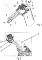
- the portable device 1 for the robotic intraoral preparation of the abutment teeth comprises a handle 11 provided at the top with a stepper motor 7, 9, 14 for each of the X, Y and Z, so that it is possible to move a turbine head 3 along guide rails 5, 6, 10 on each of the X, Y and Z axes.
- the device according to the invention comprises a fixing rail 2 mounted at one of the ends in the handle 11 of the device, and at the free end provided with a rectangular frame 4, the fixing rail 2 extending to the lower part and parallel to the turbine head arm 3, so that the bur F mounted in the turbine head 3 is controlled movable inside the frame 4 of the fixing rail 2.
- the bur is driven, in a known manner, with compressed air (see compressed air supply hose 13 in figure 1 ).
- the frame 4 is attached / mounted to the threaded bushes 15 by means of fixing screws 16, in correspondence with an opening L of a milling guide G, which is fixed in advance on the teeth by retentivity and intraosseous by means of pins 17.
- the milling machine is controlled movable on the basis of a software for realising the shape of the abutments designed virtually in the laboratory, the movement inside the frame 4 being guided on the basis of the fixing bushes 15 which constitute landmarks for moving the bur.
- the milling guide G is made of a transparent resin and has an opening L in the area in which the prosthetic abutments / columns are to be prepared.
- the device according to the invention comprises a stop button 8 in case of emergency.
- the device according to the invention comprises feeding means 12 with sterile physiological serum, with cooling role arranged in the turbine head 3.
Landscapes
- Health & Medical Sciences (AREA)
- Life Sciences & Earth Sciences (AREA)
- Animal Behavior & Ethology (AREA)
- Engineering & Computer Science (AREA)
- Veterinary Medicine (AREA)
- Public Health (AREA)
- General Health & Medical Sciences (AREA)
- Oral & Maxillofacial Surgery (AREA)
- Epidemiology (AREA)
- Dentistry (AREA)
- Surgery (AREA)
- Water Supply & Treatment (AREA)
- Molecular Biology (AREA)
- Medical Informatics (AREA)
- Heart & Thoracic Surgery (AREA)
- Biomedical Technology (AREA)
- Robotics (AREA)
- Nuclear Medicine, Radiotherapy & Molecular Imaging (AREA)
- Dental Tools And Instruments Or Auxiliary Dental Instruments (AREA)
Abstract
Description
- The invention relates to a portable device for the robotic intraoral preparation of abutment teeth for the immediate cementation of partial or total prosthetic restorations, previously performed on virtual models.
- A dental work generally aims to restore functionality and / or aesthetics and can be performed in any intraoral area, and to prepare a tooth for placement of a work, the dentist must work on the construction of the abutment teeth. Thus, after the milling of the abutment teeth, a impression of the abutment teeth is made, which is thus prepared and sent to a laboratory to carry out the respective work.
- Various robotic equipments used in the field of dentistry are known from the technical step. Various computer-generated templates are also known for use with these robotic devices.
-
US 4182312 A discloses a dental probe having a stylus which is connected through a rod to a three position transducer which produces three signals indicating the position of the probe at any point to which the probe is applied. The transducers are mounted on an index tray which is adapted to be fastened to the jaw of the patient. Thus the patient's jaw becomes the origin against which all measurements are made. A handle is connected to the probe in such a way that the dentist has three rotational degrees of freedom of movement without affecting the position of the end of the stylus. Contact between the tip of the stylus and the patient's tissue completes a circuit to turn on the recording mechanism which receives the transducers' outputs. -
DE 4012327 A1 discloses a dental jaw model or similar undergoes an ideal preparation corresponding to the specified task and an analysis by a parallelometer, using a parallelometer grinding system. The preparation data are further transmitted to a computer and a 3-D milling unit and a grinding body, and servo motors are used with horizontal and vertical rotors. A milling template is adapted for positioning in the mouth of the patient, e.g. using a turbine grinder or a grinding body. Following the positioning and fixing of the template(s) in the mouth of the patient, the scanning of the grinding body is carried out through the milled out part of the template and the ideal preparation of the jaw model is transmitted to the natural teeth. Also supplied across the cable connections are rotary and linear potentiometers, photo-electric measurement systems and laser interferometer or similar as displacement and angle sensors. - From document
US 2014242541 A1 a dental cutting system and method for cutting a patient's tooth are known. The dental cutting system includes a hand piece to be held and carrying a cutting burr to cut the patient's tooth. A plurality of guide pins is attached to and extends from the hand piece of the cutting tool remote from the cutting bur. One or more cutting guides each have a cavity coinciding with at least a portion of teeth inside a patient's mouth that are adjacent to or remote from the patient's tooth to be cut. The guide pins of the handpiece slide in slots in the cutting guide to guide the burr to cut the patient's tooth. - The present invention aims to provide a portable device for the robotic intraoral preparation of abutment teeth, which completely eliminates the talent and experience factors associated with the doctor performing the operation, and which allows an accurate, clear and correct realisation of abutment teeth, for a prefabricated job through a method that removes the imprinting of the prepared abutment teeth.
- The solution to this problem is a portable device for the robotic intraoral preparation of the abutment teeth comprising a handle provided at the top with a stepper motor for each of the X, Y and Z axes, so that it is possible to move a turbine head along guide rails on each of the X, Y and Z axes, wherein the device comprises a fixing rail mounted at one end in the handle of the device, and at the free end provided with a rectangular frame, the fixing rail extends at the bottom part and is parallel to the turbine head arm, so that the bur mounted in the turbine head is controlled movable inside the frame of the fixing rail, and in which the frame is mounted by means of fixing screws in threaded bushes, in correspondence with an opening of a milling guide, which is fixed in advance on the teeth by retentivity and intraosseous by means of pins.
- In a preferred embodiment of the device according to the present invention, the bur is controlled movable on the basis of a software for making the shape of abutments designed virtually in the laboratory, the movement inside the frame being guided on the basis of fixing bushes.
- In a preferred embodiment of the device according to the present invention, the milling guide is made of a transparent resin over the milling guide.
- Preferably, the device according to the present invention comprises an emergency stop button.
- In an advantageous way, the device according to the present invention comprises feeding means with sterile physiological serum, with cooling role, arranged in the turbine head.
- The present invention has the following advantages and contributes to the elimination of aspects related to:
- Subjective factors that relate to the skill and experience of the doctor,
- Excessive grinding of the abutment teeth,
- The unexpected final result, which is unpleasantly identified with various unacceptable "technical" explanations, such as: lack of interdental space, defective bite, urgency of the procedure, late hour etc.
- The realisation by the technician of some unwanted compromises, corrections and artifices in order to mask the doctor's errors in the preparation of the abutment teeth, which will lead to the accomplishment of some unsightly works, incorrectly performed, with short life,
- The use of materials and methods of classical imprinting, with the associated increase of the total time of accomplishing the dental work,
- Any type of imprinting of the prepared abutment teeth, thus eliminating the inaccuracies that are transmitted to the laboratory
- The at least 7 visits during at least 3 weeks to obtain the final works in the classic version
- Large irregularities regarding the space between the column and the dental crown, which lead to very different thicknesses of the cement layer used in the prosthetic work, which implicitly in time leads to its fracturing and to the partial or total decimation of the works.
- Other objects, features and advantages of the present invention will become more apparent from the following detailed description of a preferred embodiment, given by way of non-limiting example, of the portable device for the robotic intraoral preparation of abutment teeth, in connection with the appended figures, wherein :
-
Fig. 1 is an overview of the portable device for the robotic intraoral preparation of abutment teeth, according to the present invention; -
Fig. 2 is an overview of the portable device for the robotic intraoral preparation of the abutment teeth, according to the present invention, in the working position; -
Fig. 3 and 4 are detailed views of the position of the frame for fixing the portable device for the robotic intraoral preparation of the abutment teeth, according to the present invention, in relation to the milling guide; -
Fig. 5 is an overview of a simplified example of a milling guide made of transparent resin; - In connection with the appended figures, and for a clearer and more comprehensive understanding of the present invention, the entire sequence of the steps for preparing the dental work in which the portable device for the robotic intraoral preparation of the abutment teeth is used according to the present invention will be further presented.
- In a first step, the photos are taken with the patient's smile, with a simple camera, ideally with a white background and the introduction of images in a existing software for simulating dental treatment - a step made in the dental office.
- Following next is the virtual simulation of the future smile - Virtual mock-up and the presentation of the materials from which the work can be done, the costs, the patient's agreement for the shape, colour, and cost. This step is performed in the clinic or laboratory.
- Coronary reconstruction is then performed by specific methods known when appropriate (step performed in the office), and intraoral scanning of both arches, as well as occlusion with a known intraoral scanner (step performed in the clinic), after which the images and intraoral scanning (step performed in the office) are sent to the laboratory / doctor.
- Next, the laboratory / doctor creates a virtual mock-up (virtual volumetric simulation of the future work), in a specific program, existing in the laboratory (step performed in the laboratory).
- Then the printing of a model after mock-up and the realisation of a temporary work milled from a temporary material, which simulates the final work (step performed in the laboratory).
- The temporary intraoral work is cemented with dental bonding or resin cement (step performed in the clinic).
- Depending on the clinical context, if necessary, in the same session or after about 2 days, the temporary work will be adapted to the patient's usual occlusion, as well as to the patient's aesthetic demands (step performed in the office).
- After the patient's consent for the final work - form + material, there is an intraoral scan of the arch or arches which will be replaced by prosthetics, as well as the occlusion with the temporary intraoral work, and the removal or not of the temporary work, according to the patient's wish (step performed in clinic).
- Intraoral scanning data and the creation of a milling guide through an existing dental program are then transmitted to the laboratory. The milling guide can be made of a transparent resin for surgical guides, on the entire arch, with 4 recesses, with metal reinforcement, for gripping the rail of the device for robotic intraoral preparation of abutment teeth, as will be detailed below. The milling guide is provided with an opening in the area in which the prosthetic abutments / pillars are to be prepared and with 3-5 holes for the bone fixation of the guide with pins, intraorally.
- In order to achieve the final work in the form and material agreed by the patient, the virtual reduction of each pillar in the model scanned with the temporary work, with a shape and thickness specific to the material from which the final work is to be performed, in an existing dental program, and at the end of this step, a virtual model will be obtained with the abutments on which the final work is to be based (the step is performed in the laboratory).
- In the situation where there are vital pillar teeth, the need for their devitalisation will be analysed and decided, following the realisation of the devitalisations and canal fillings considered to be necessary (step performed in the clinic).
- Then the printing and analysis of the model with the abutments to be obtained is performed and the virtual realisation of the final work on the virtual model obtained (step performed in the laboratory).
- The final work is tested on the printed model and the milling guide is fixed on the printed or cast model of the temporary work, the device for robotic intraoral preparation is fixed on the milling guide and the verification/simulation, with an active diamond bur on the material device, of the abutment preparation with the help of the device, on the model. Then the verification of the adaptation of the final work on the model thus obtained takes place (step performed in the laboratory).
- Anaesthesia of the areas to be prepared takes place and the intraoral milling guide is fixed on the existing teeth to be prepared and, if necessary, intraosseous by means of pins, and the calibration of the robotic intraoral preparation of the abutment teeth on the guide and the mounting of the occlusal stops. In the situation that the work has a size exceeding 6 teeth, then it is necessary to make two milling guides, the first for 1 hemiarcade, according to the initial situation, and the second one based on the situation obtained after using the first guide and preparing the abutment teeth.
the bur to be used together with the portable device for robotic intraoral preparation of abutment teeth is mounted, according to the present invention, the verification of the milling rotation settings as well as the operation of the cooling irrigation takes place. The fixing rail attaches to the milling guide and then the portable device is operated for the robotic intraoral preparation of the abutment teeth. - After preparation, the intraoral work is tested and the final or provisional cementing takes place, if required.
- Going back to the accompanying figures, the
portable device 1 for the robotic intraoral preparation of the abutment teeth, according to the present invention, comprises ahandle 11 provided at the top with astepper motor turbine head 3 alongguide rails - The device according to the invention comprises a
fixing rail 2 mounted at one of the ends in thehandle 11 of the device, and at the free end provided with arectangular frame 4, thefixing rail 2 extending to the lower part and parallel to theturbine head arm 3, so that the bur F mounted in theturbine head 3 is controlled movable inside theframe 4 of thefixing rail 2. the bur is driven, in a known manner, with compressed air (see compressedair supply hose 13 infigure 1 ). - With particular reference to
Figures 3 and 4 , theframe 4 is attached / mounted to the threadedbushes 15 by means of fixingscrews 16, in correspondence with an opening L of a milling guide G, which is fixed in advance on the teeth by retentivity and intraosseous by means ofpins 17. - According to the invention, the milling machine is controlled movable on the basis of a software for realising the shape of the abutments designed virtually in the laboratory, the movement inside the
frame 4 being guided on the basis of the fixingbushes 15 which constitute landmarks for moving the bur. - With reference to
Figure 5 , and as mentioned above, the milling guide G is made of a transparent resin and has an opening L in the area in which the prosthetic abutments / columns are to be prepared. - Advantageously, the device according to the invention comprises a
stop button 8 in case of emergency. - Also, as mentioned above, the device according to the invention comprises feeding means 12 with sterile physiological serum, with cooling role arranged in the
turbine head 3. - One skilled in the art will appreciate that the invention has been disclosed above in an illustrative and non-limiting manner, and that numerous modifications and changes may be made within the scope of the invention without departing from the scope of the invention as defined in the appended claims.
Claims (6)
- A portable device for robotic intraoral preparation of abutment teeth comprising a handle (11) provided at the top with a stepper motor (7, 9, 14) for each of the X, Y and Z axes, so that it is possible moving a turbine head (3) along guide rails (5, 6, 10) on each of the X, Y and Z axes, wherein the device comprises a fixing rail (2) mounted at one of the ends in the handle (11) of the device, and at the free end provided with a rectangular frame (4), the fixing rail (2) extending to the lower part and parallel to the arm of the turbine head (3), so that the bur (F) mounted in the turbine head (3) is movably controlled inside the frame (4) of the fixing rail (2), and in which the frame (4) is mounted by means of fixing screws (16) in threaded bushes (15), in correspondence with an opening (L) of a milling guide (G), which is fixed in advance on the teeth by retentivity and intraosseous by means of pins (17).
- The device according to claim 1, characterised in that the bur (F) is controlled movable on the basis of a software for making the shape of abutments designed virtually in the laboratory, the movement inside the frame (4) being guided on the basis of the fixing bushes (15) which constitute diamond bur movement marks.
- The device according to Claim 1 or 2, characterised in that said frame (4) is rigidly attached to the milling guide (G).
- The device according to one of Claims 1 to 3, characterised in that the milling guide (G) is made of a transparent resin having said opening (L) in the area in which the prosthetic abutments / columns are to be prepared.
- The device according to one of Claims 1 to 4, characterised in that it comprises an emergency stop button (8).
- The device according to one of Claims 1 to 5, characterised in that it comprises means for supplying (12) a sterile physiological serum with cooling role, arranged in the turbine head (3).
Priority Applications (1)
| Application Number | Priority Date | Filing Date | Title |
|---|---|---|---|
| EP20203766.9A EP3834769B1 (en) | 2020-10-26 | 2020-10-26 | Portable device for robotic intraoral preparation of abutment teeth |
Applications Claiming Priority (1)
| Application Number | Priority Date | Filing Date | Title |
|---|---|---|---|
| EP20203766.9A EP3834769B1 (en) | 2020-10-26 | 2020-10-26 | Portable device for robotic intraoral preparation of abutment teeth |
Publications (2)
| Publication Number | Publication Date |
|---|---|
| EP3834769A1 true EP3834769A1 (en) | 2021-06-16 |
| EP3834769B1 EP3834769B1 (en) | 2023-01-25 |
Family
ID=73014412
Family Applications (1)
| Application Number | Title | Priority Date | Filing Date |
|---|---|---|---|
| EP20203766.9A Active EP3834769B1 (en) | 2020-10-26 | 2020-10-26 | Portable device for robotic intraoral preparation of abutment teeth |
Country Status (1)
| Country | Link |
|---|---|
| EP (1) | EP3834769B1 (en) |
Cited By (2)
| Publication number | Priority date | Publication date | Assignee | Title |
|---|---|---|---|---|
| CN116585051A (en) * | 2023-05-04 | 2023-08-15 | 中国科学院大学深圳医院(光明) | An automatic dental preparation system for dental clinics |
| CN117281635A (en) * | 2023-11-24 | 2023-12-26 | 四川大学 | Automatic grinding and drilling device for dental caries |
Citations (6)
| Publication number | Priority date | Publication date | Assignee | Title |
|---|---|---|---|---|
| US4182312A (en) | 1977-05-20 | 1980-01-08 | Mushabac David R | Dental probe |
| DE4012327A1 (en) | 1990-04-18 | 1991-10-24 | Schreiber Hans | Producing dental workpieces by copy milling - using dental jaw model for reception of dental workpiece which is ground in established direction on basis of milling template |
| WO1994003120A1 (en) * | 1992-07-31 | 1994-02-17 | Beckett Corporation Limited | Improvements in and relating to dentistry |
| US20140242541A1 (en) | 2013-02-27 | 2014-08-28 | DigitalPrep Technologies, Inc. | Dental cutting system and method with remote cutting guide |
| US9554872B2 (en) * | 2012-05-04 | 2017-01-31 | Stephen KOUBI | Intraoral device for automated preparation of the teeth with a view to performing partial or peripheral restorations |
| WO2020105052A1 (en) * | 2018-11-23 | 2020-05-28 | Drobotics Ltd. | Devices and methods for shaping a tooth |
-
2020
- 2020-10-26 EP EP20203766.9A patent/EP3834769B1/en active Active
Patent Citations (6)
| Publication number | Priority date | Publication date | Assignee | Title |
|---|---|---|---|---|
| US4182312A (en) | 1977-05-20 | 1980-01-08 | Mushabac David R | Dental probe |
| DE4012327A1 (en) | 1990-04-18 | 1991-10-24 | Schreiber Hans | Producing dental workpieces by copy milling - using dental jaw model for reception of dental workpiece which is ground in established direction on basis of milling template |
| WO1994003120A1 (en) * | 1992-07-31 | 1994-02-17 | Beckett Corporation Limited | Improvements in and relating to dentistry |
| US9554872B2 (en) * | 2012-05-04 | 2017-01-31 | Stephen KOUBI | Intraoral device for automated preparation of the teeth with a view to performing partial or peripheral restorations |
| US20140242541A1 (en) | 2013-02-27 | 2014-08-28 | DigitalPrep Technologies, Inc. | Dental cutting system and method with remote cutting guide |
| WO2020105052A1 (en) * | 2018-11-23 | 2020-05-28 | Drobotics Ltd. | Devices and methods for shaping a tooth |
Cited By (5)
| Publication number | Priority date | Publication date | Assignee | Title |
|---|---|---|---|---|
| CN116585051A (en) * | 2023-05-04 | 2023-08-15 | 中国科学院大学深圳医院(光明) | An automatic dental preparation system for dental clinics |
| CN116585051B (en) * | 2023-05-04 | 2024-05-28 | 中国科学院大学深圳医院(光明) | An automated tooth preparation system for oral clinics |
| CN117281635A (en) * | 2023-11-24 | 2023-12-26 | 四川大学 | Automatic grinding and drilling device for dental caries |
| CN117281635B (en) * | 2023-11-24 | 2024-01-30 | 四川大学 | Automatic grinding and drilling device for dental caries |
| US12171624B1 (en) | 2023-11-24 | 2024-12-24 | Sichuan University | Automatic grinding drill device for oral caries |
Also Published As
| Publication number | Publication date |
|---|---|
| EP3834769B1 (en) | 2023-01-25 |
Similar Documents
| Publication | Publication Date | Title |
|---|---|---|
| CN104519825B (en) | An automatic intraoral dental preparation device for local dental restoration or peripheral nerve restoration | |
| US20220401184A1 (en) | Reduced registration bonding template | |
| JP6949932B2 (en) | Computer-executed dental restoration design | |
| JP4902802B2 (en) | Denture grinding method, pre-dental denture grinding part calculation program, and occlusal state reproduction device | |
| RU2740157C2 (en) | Dental instrument | |
| CN110461267B (en) | Jaw correction system using three-dimensional hybrid image construction procedure | |
| AU2019360367B2 (en) | Method for designing a prosthetic element | |
| HUP1000387A2 (en) | Process and apparatus for computer-controlled restoration of teeth | |
| EP3834769B1 (en) | Portable device for robotic intraoral preparation of abutment teeth | |
| Kim et al. | Clinical experiences of digital model surgery and the rapid-prototyped wafer for maxillary orthognathic surgery | |
| Tsukiboshi | Digital simulation and designing of a novel osteotomy guide for autotransplantation in the anterior region | |
| WO2019003452A1 (en) | Ct imaging reference marker, three-dimensional tomogram creation method, matching method, and system therefor | |
| EP3375401B1 (en) | Template and method for planning the surgery of dental implants and/or guided placement of a prosthesis on implants | |
| Zhou et al. | Comparing the effectiveness of a robotic and dynamic navigation system in fiber post removal: an in vitro study | |
| Pandey et al. | Intelligent Prosthodontics, Intelligent Implantology, and Intelligent Full Mouth Rehabilitation | |
| Sharma | Going Digital in a Prosthodontic Clinic: Technologies and Workflow | |
| US20210401540A1 (en) | Instantaneous dental implant surgery guiding device and method thereof | |
| RU2857443C1 (en) | Method for manufacturing template for preparing vital teeth for artificial crowns | |
| RU2857442C1 (en) | Method for preparing abutment teeth for fixed prosthetic structures to preserve their vitality | |
| RU2822955C1 (en) | Method for teeth immobilization with milled ceramic splints | |
| RU2708030C1 (en) | Method for movable teeth immobilization | |
| Sirikajorndetsakul et al. | Clinical and Laboratory Workflow for Digital Complete Denture. | |
| KR20210155847A (en) | Instantaneous dental implant surgery guiding device and method thereof | |
| Lyu et al. | Digitally guided occlusal adjustment for reestablishing equilibrium | |
| TW202130329A (en) | Immediate dental implantation surgery guide apparatus and method thereof mainly including a base body, an accommodating space, a ball, a through hole, and an adjusting element |
Legal Events
| Date | Code | Title | Description |
|---|---|---|---|
| PUAI | Public reference made under article 153(3) epc to a published international application that has entered the european phase |
Free format text: ORIGINAL CODE: 0009012 |
|
| STAA | Information on the status of an ep patent application or granted ep patent |
Free format text: STATUS: REQUEST FOR EXAMINATION WAS MADE |
|
| 17P | Request for examination filed |
Effective date: 20210504 |
|
| AK | Designated contracting states |
Kind code of ref document: A1 Designated state(s): AL AT BE BG CH CY CZ DE DK EE ES FI FR GB GR HR HU IE IS IT LI LT LU LV MC MK MT NL NO PL PT RO RS SE SI SK SM TR |
|
| STAA | Information on the status of an ep patent application or granted ep patent |
Free format text: STATUS: EXAMINATION IS IN PROGRESS |
|
| 17Q | First examination report despatched |
Effective date: 20211028 |
|
| GRAP | Despatch of communication of intention to grant a patent |
Free format text: ORIGINAL CODE: EPIDOSNIGR1 |
|
| STAA | Information on the status of an ep patent application or granted ep patent |
Free format text: STATUS: GRANT OF PATENT IS INTENDED |
|
| INTG | Intention to grant announced |
Effective date: 20220701 |
|
| GRAS | Grant fee paid |
Free format text: ORIGINAL CODE: EPIDOSNIGR3 |
|
| GRAA | (expected) grant |
Free format text: ORIGINAL CODE: 0009210 |
|
| STAA | Information on the status of an ep patent application or granted ep patent |
Free format text: STATUS: THE PATENT HAS BEEN GRANTED |
|
| AK | Designated contracting states |
Kind code of ref document: B1 Designated state(s): AL AT BE BG CH CY CZ DE DK EE ES FI FR GB GR HR HU IE IS IT LI LT LU LV MC MK MT NL NO PL PT RO RS SE SI SK SM TR |
|
| REG | Reference to a national code |
Ref country code: GB Ref legal event code: FG4D |
|
| REG | Reference to a national code |
Ref country code: CH Ref legal event code: EP |
|
| REG | Reference to a national code |
Ref country code: DE Ref legal event code: R096 Ref document number: 602020007821 Country of ref document: DE |
|
| REG | Reference to a national code |
Ref country code: AT Ref legal event code: REF Ref document number: 1545463 Country of ref document: AT Kind code of ref document: T Effective date: 20230215 Ref country code: IE Ref legal event code: FG4D |
|
| REG | Reference to a national code |
Ref country code: LT Ref legal event code: MG9D |
|
| REG | Reference to a national code |
Ref country code: NL Ref legal event code: MP Effective date: 20230125 |
|
| REG | Reference to a national code |
Ref country code: AT Ref legal event code: MK05 Ref document number: 1545463 Country of ref document: AT Kind code of ref document: T Effective date: 20230125 |
|
| PG25 | Lapsed in a contracting state [announced via postgrant information from national office to epo] |
Ref country code: NL Free format text: LAPSE BECAUSE OF FAILURE TO SUBMIT A TRANSLATION OF THE DESCRIPTION OR TO PAY THE FEE WITHIN THE PRESCRIBED TIME-LIMIT Effective date: 20230125 |
|
| PG25 | Lapsed in a contracting state [announced via postgrant information from national office to epo] |
Ref country code: RS Free format text: LAPSE BECAUSE OF FAILURE TO SUBMIT A TRANSLATION OF THE DESCRIPTION OR TO PAY THE FEE WITHIN THE PRESCRIBED TIME-LIMIT Effective date: 20230125 Ref country code: PT Free format text: LAPSE BECAUSE OF FAILURE TO SUBMIT A TRANSLATION OF THE DESCRIPTION OR TO PAY THE FEE WITHIN THE PRESCRIBED TIME-LIMIT Effective date: 20230525 Ref country code: NO Free format text: LAPSE BECAUSE OF FAILURE TO SUBMIT A TRANSLATION OF THE DESCRIPTION OR TO PAY THE FEE WITHIN THE PRESCRIBED TIME-LIMIT Effective date: 20230425 Ref country code: LV Free format text: LAPSE BECAUSE OF FAILURE TO SUBMIT A TRANSLATION OF THE DESCRIPTION OR TO PAY THE FEE WITHIN THE PRESCRIBED TIME-LIMIT Effective date: 20230125 Ref country code: LT Free format text: LAPSE BECAUSE OF FAILURE TO SUBMIT A TRANSLATION OF THE DESCRIPTION OR TO PAY THE FEE WITHIN THE PRESCRIBED TIME-LIMIT Effective date: 20230125 Ref country code: HR Free format text: LAPSE BECAUSE OF FAILURE TO SUBMIT A TRANSLATION OF THE DESCRIPTION OR TO PAY THE FEE WITHIN THE PRESCRIBED TIME-LIMIT Effective date: 20230125 Ref country code: ES Free format text: LAPSE BECAUSE OF FAILURE TO SUBMIT A TRANSLATION OF THE DESCRIPTION OR TO PAY THE FEE WITHIN THE PRESCRIBED TIME-LIMIT Effective date: 20230125 Ref country code: AT Free format text: LAPSE BECAUSE OF FAILURE TO SUBMIT A TRANSLATION OF THE DESCRIPTION OR TO PAY THE FEE WITHIN THE PRESCRIBED TIME-LIMIT Effective date: 20230125 |
|
| PG25 | Lapsed in a contracting state [announced via postgrant information from national office to epo] |
Ref country code: SE Free format text: LAPSE BECAUSE OF FAILURE TO SUBMIT A TRANSLATION OF THE DESCRIPTION OR TO PAY THE FEE WITHIN THE PRESCRIBED TIME-LIMIT Effective date: 20230125 Ref country code: PL Free format text: LAPSE BECAUSE OF FAILURE TO SUBMIT A TRANSLATION OF THE DESCRIPTION OR TO PAY THE FEE WITHIN THE PRESCRIBED TIME-LIMIT Effective date: 20230125 Ref country code: IS Free format text: LAPSE BECAUSE OF FAILURE TO SUBMIT A TRANSLATION OF THE DESCRIPTION OR TO PAY THE FEE WITHIN THE PRESCRIBED TIME-LIMIT Effective date: 20230525 Ref country code: GR Free format text: LAPSE BECAUSE OF FAILURE TO SUBMIT A TRANSLATION OF THE DESCRIPTION OR TO PAY THE FEE WITHIN THE PRESCRIBED TIME-LIMIT Effective date: 20230426 Ref country code: FI Free format text: LAPSE BECAUSE OF FAILURE TO SUBMIT A TRANSLATION OF THE DESCRIPTION OR TO PAY THE FEE WITHIN THE PRESCRIBED TIME-LIMIT Effective date: 20230125 |
|
| REG | Reference to a national code |
Ref country code: DE Ref legal event code: R097 Ref document number: 602020007821 Country of ref document: DE |
|
| PG25 | Lapsed in a contracting state [announced via postgrant information from national office to epo] |
Ref country code: SM Free format text: LAPSE BECAUSE OF FAILURE TO SUBMIT A TRANSLATION OF THE DESCRIPTION OR TO PAY THE FEE WITHIN THE PRESCRIBED TIME-LIMIT Effective date: 20230125 Ref country code: EE Free format text: LAPSE BECAUSE OF FAILURE TO SUBMIT A TRANSLATION OF THE DESCRIPTION OR TO PAY THE FEE WITHIN THE PRESCRIBED TIME-LIMIT Effective date: 20230125 Ref country code: DK Free format text: LAPSE BECAUSE OF FAILURE TO SUBMIT A TRANSLATION OF THE DESCRIPTION OR TO PAY THE FEE WITHIN THE PRESCRIBED TIME-LIMIT Effective date: 20230125 Ref country code: CZ Free format text: LAPSE BECAUSE OF FAILURE TO SUBMIT A TRANSLATION OF THE DESCRIPTION OR TO PAY THE FEE WITHIN THE PRESCRIBED TIME-LIMIT Effective date: 20230125 |
|
| PG25 | Lapsed in a contracting state [announced via postgrant information from national office to epo] |
Ref country code: SK Free format text: LAPSE BECAUSE OF FAILURE TO SUBMIT A TRANSLATION OF THE DESCRIPTION OR TO PAY THE FEE WITHIN THE PRESCRIBED TIME-LIMIT Effective date: 20230125 |
|
| PLBE | No opposition filed within time limit |
Free format text: ORIGINAL CODE: 0009261 |
|
| STAA | Information on the status of an ep patent application or granted ep patent |
Free format text: STATUS: NO OPPOSITION FILED WITHIN TIME LIMIT |
|
| 26N | No opposition filed |
Effective date: 20231026 |
|
| PG25 | Lapsed in a contracting state [announced via postgrant information from national office to epo] |
Ref country code: SI Free format text: LAPSE BECAUSE OF FAILURE TO SUBMIT A TRANSLATION OF THE DESCRIPTION OR TO PAY THE FEE WITHIN THE PRESCRIBED TIME-LIMIT Effective date: 20230125 |
|
| PG25 | Lapsed in a contracting state [announced via postgrant information from national office to epo] |
Ref country code: IT Free format text: LAPSE BECAUSE OF FAILURE TO SUBMIT A TRANSLATION OF THE DESCRIPTION OR TO PAY THE FEE WITHIN THE PRESCRIBED TIME-LIMIT Effective date: 20230125 Ref country code: MC Free format text: LAPSE BECAUSE OF FAILURE TO SUBMIT A TRANSLATION OF THE DESCRIPTION OR TO PAY THE FEE WITHIN THE PRESCRIBED TIME-LIMIT Effective date: 20230125 |
|
| REG | Reference to a national code |
Ref country code: CH Ref legal event code: PL |
|
| REG | Reference to a national code |
Ref country code: BE Ref legal event code: MM Effective date: 20231031 |
|
| PG25 | Lapsed in a contracting state [announced via postgrant information from national office to epo] |
Ref country code: LU Free format text: LAPSE BECAUSE OF NON-PAYMENT OF DUE FEES Effective date: 20231026 |
|
| PG25 | Lapsed in a contracting state [announced via postgrant information from national office to epo] |
Ref country code: LU Free format text: LAPSE BECAUSE OF NON-PAYMENT OF DUE FEES Effective date: 20231026 |
|
| PG25 | Lapsed in a contracting state [announced via postgrant information from national office to epo] |
Ref country code: CH Free format text: LAPSE BECAUSE OF NON-PAYMENT OF DUE FEES Effective date: 20231031 |
|
| PG25 | Lapsed in a contracting state [announced via postgrant information from national office to epo] |
Ref country code: FR Free format text: LAPSE BECAUSE OF NON-PAYMENT OF DUE FEES Effective date: 20231031 Ref country code: CH Free format text: LAPSE BECAUSE OF NON-PAYMENT OF DUE FEES Effective date: 20231031 |
|
| PG25 | Lapsed in a contracting state [announced via postgrant information from national office to epo] |
Ref country code: BE Free format text: LAPSE BECAUSE OF NON-PAYMENT OF DUE FEES Effective date: 20231031 |
|
| PG25 | Lapsed in a contracting state [announced via postgrant information from national office to epo] |
Ref country code: IE Free format text: LAPSE BECAUSE OF NON-PAYMENT OF DUE FEES Effective date: 20231026 |
|
| PG25 | Lapsed in a contracting state [announced via postgrant information from national office to epo] |
Ref country code: IE Free format text: LAPSE BECAUSE OF NON-PAYMENT OF DUE FEES Effective date: 20231026 |
|
| PG25 | Lapsed in a contracting state [announced via postgrant information from national office to epo] |
Ref country code: BG Free format text: LAPSE BECAUSE OF FAILURE TO SUBMIT A TRANSLATION OF THE DESCRIPTION OR TO PAY THE FEE WITHIN THE PRESCRIBED TIME-LIMIT Effective date: 20230125 |
|
| PG25 | Lapsed in a contracting state [announced via postgrant information from national office to epo] |
Ref country code: BG Free format text: LAPSE BECAUSE OF FAILURE TO SUBMIT A TRANSLATION OF THE DESCRIPTION OR TO PAY THE FEE WITHIN THE PRESCRIBED TIME-LIMIT Effective date: 20230125 |
|
| PGFP | Annual fee paid to national office [announced via postgrant information from national office to epo] |
Ref country code: DE Payment date: 20241107 Year of fee payment: 5 |
|
| PGFP | Annual fee paid to national office [announced via postgrant information from national office to epo] |
Ref country code: RO Payment date: 20241015 Year of fee payment: 5 |
|
| PG25 | Lapsed in a contracting state [announced via postgrant information from national office to epo] |
Ref country code: CY Free format text: LAPSE BECAUSE OF FAILURE TO SUBMIT A TRANSLATION OF THE DESCRIPTION OR TO PAY THE FEE WITHIN THE PRESCRIBED TIME-LIMIT; INVALID AB INITIO Effective date: 20201026 |
|
| PG25 | Lapsed in a contracting state [announced via postgrant information from national office to epo] |
Ref country code: HU Free format text: LAPSE BECAUSE OF FAILURE TO SUBMIT A TRANSLATION OF THE DESCRIPTION OR TO PAY THE FEE WITHIN THE PRESCRIBED TIME-LIMIT; INVALID AB INITIO Effective date: 20201026 |
|
| PGFP | Annual fee paid to national office [announced via postgrant information from national office to epo] |
Ref country code: GB Payment date: 20250811 Year of fee payment: 6 |
|
| PG25 | Lapsed in a contracting state [announced via postgrant information from national office to epo] |
Ref country code: TR Free format text: LAPSE BECAUSE OF FAILURE TO SUBMIT A TRANSLATION OF THE DESCRIPTION OR TO PAY THE FEE WITHIN THE PRESCRIBED TIME-LIMIT Effective date: 20230125 |