EP3834741A1 - System and method for temporarily and permanently disabling electronics in a disposable surgical tool - Google Patents
System and method for temporarily and permanently disabling electronics in a disposable surgical tool Download PDFInfo
- Publication number
- EP3834741A1 EP3834741A1 EP20212940.9A EP20212940A EP3834741A1 EP 3834741 A1 EP3834741 A1 EP 3834741A1 EP 20212940 A EP20212940 A EP 20212940A EP 3834741 A1 EP3834741 A1 EP 3834741A1
- Authority
- EP
- European Patent Office
- Prior art keywords
- circuit
- fuse
- safety cut
- transistor
- coupled
- Prior art date
- Legal status (The legal status is an assumption and is not a legal conclusion. Google has not performed a legal analysis and makes no representation as to the accuracy of the status listed.)
- Withdrawn
Links
- 238000000034 method Methods 0.000 title description 11
- 239000007788 liquid Substances 0.000 claims abstract description 93
- 238000001514 detection method Methods 0.000 claims abstract description 71
- 230000001960 triggered effect Effects 0.000 claims description 15
- XLYOFNOQVPJJNP-UHFFFAOYSA-N water Substances O XLYOFNOQVPJJNP-UHFFFAOYSA-N 0.000 claims description 7
- 238000001356 surgical procedure Methods 0.000 description 4
- 206010019909 Hernia Diseases 0.000 description 3
- 210000003815 abdominal wall Anatomy 0.000 description 3
- 238000010586 diagram Methods 0.000 description 3
- 238000006073 displacement reaction Methods 0.000 description 3
- 230000006870 function Effects 0.000 description 3
- 208000029836 Inguinal Hernia Diseases 0.000 description 2
- 230000008901 benefit Effects 0.000 description 2
- 238000007664 blowing Methods 0.000 description 2
- 230000007547 defect Effects 0.000 description 2
- 238000012986 modification Methods 0.000 description 2
- 230000004048 modification Effects 0.000 description 2
- 230000003287 optical effect Effects 0.000 description 2
- 238000004873 anchoring Methods 0.000 description 1
- 238000003491 array Methods 0.000 description 1
- 230000005540 biological transmission Effects 0.000 description 1
- 230000001010 compromised effect Effects 0.000 description 1
- 238000010276 construction Methods 0.000 description 1
- 230000008878 coupling Effects 0.000 description 1
- 238000010168 coupling process Methods 0.000 description 1
- 238000005859 coupling reaction Methods 0.000 description 1
- 238000013500 data storage Methods 0.000 description 1
- 230000000994 depressogenic effect Effects 0.000 description 1
- 230000000694 effects Effects 0.000 description 1
- 210000003811 finger Anatomy 0.000 description 1
- 238000003780 insertion Methods 0.000 description 1
- 230000037431 insertion Effects 0.000 description 1
- 210000000936 intestine Anatomy 0.000 description 1
- 230000000116 mitigating effect Effects 0.000 description 1
- 230000008569 process Effects 0.000 description 1
- 238000012545 processing Methods 0.000 description 1
- 230000002787 reinforcement Effects 0.000 description 1
- 230000008439 repair process Effects 0.000 description 1
- 210000003813 thumb Anatomy 0.000 description 1
- 238000013519 translation Methods 0.000 description 1
- 238000011144 upstream manufacturing Methods 0.000 description 1
Images


Classifications
-
- A—HUMAN NECESSITIES
- A61—MEDICAL OR VETERINARY SCIENCE; HYGIENE
- A61B—DIAGNOSIS; SURGERY; IDENTIFICATION
- A61B18/00—Surgical instruments, devices or methods for transferring non-mechanical forms of energy to or from the body
- A61B18/04—Surgical instruments, devices or methods for transferring non-mechanical forms of energy to or from the body by heating
- A61B18/12—Surgical instruments, devices or methods for transferring non-mechanical forms of energy to or from the body by heating by passing a current through the tissue to be heated, e.g. high-frequency current
- A61B18/1206—Generators therefor
- A61B18/1233—Generators therefor with circuits for assuring patient safety
-
- A—HUMAN NECESSITIES
- A61—MEDICAL OR VETERINARY SCIENCE; HYGIENE
- A61B—DIAGNOSIS; SURGERY; IDENTIFICATION
- A61B17/00—Surgical instruments, devices or methods
- A61B17/064—Surgical staples, i.e. penetrating the tissue
-
- A—HUMAN NECESSITIES
- A61—MEDICAL OR VETERINARY SCIENCE; HYGIENE
- A61B—DIAGNOSIS; SURGERY; IDENTIFICATION
- A61B17/00—Surgical instruments, devices or methods
- A61B17/068—Surgical staplers, e.g. containing multiple staples or clamps
-
- A—HUMAN NECESSITIES
- A61—MEDICAL OR VETERINARY SCIENCE; HYGIENE
- A61B—DIAGNOSIS; SURGERY; IDENTIFICATION
- A61B17/00—Surgical instruments, devices or methods
- A61B17/00234—Surgical instruments, devices or methods for minimally invasive surgery
-
- H—ELECTRICITY
- H01—ELECTRIC ELEMENTS
- H01M—PROCESSES OR MEANS, e.g. BATTERIES, FOR THE DIRECT CONVERSION OF CHEMICAL ENERGY INTO ELECTRICAL ENERGY
- H01M10/00—Secondary cells; Manufacture thereof
- H01M10/42—Methods or arrangements for servicing or maintenance of secondary cells or secondary half-cells
- H01M10/425—Structural combination with electronic components, e.g. electronic circuits integrated to the outside of the casing
-
- H—ELECTRICITY
- H01—ELECTRIC ELEMENTS
- H01M—PROCESSES OR MEANS, e.g. BATTERIES, FOR THE DIRECT CONVERSION OF CHEMICAL ENERGY INTO ELECTRICAL ENERGY
- H01M10/00—Secondary cells; Manufacture thereof
- H01M10/42—Methods or arrangements for servicing or maintenance of secondary cells or secondary half-cells
- H01M10/48—Accumulators combined with arrangements for measuring, testing or indicating the condition of cells, e.g. the level or density of the electrolyte
-
- H—ELECTRICITY
- H01—ELECTRIC ELEMENTS
- H01M—PROCESSES OR MEANS, e.g. BATTERIES, FOR THE DIRECT CONVERSION OF CHEMICAL ENERGY INTO ELECTRICAL ENERGY
- H01M50/00—Constructional details or processes of manufacture of the non-active parts of electrochemical cells other than fuel cells, e.g. hybrid cells
- H01M50/50—Current conducting connections for cells or batteries
- H01M50/572—Means for preventing undesired use or discharge
- H01M50/574—Devices or arrangements for the interruption of current
- H01M50/583—Devices or arrangements for the interruption of current in response to current, e.g. fuses
-
- A—HUMAN NECESSITIES
- A61—MEDICAL OR VETERINARY SCIENCE; HYGIENE
- A61B—DIAGNOSIS; SURGERY; IDENTIFICATION
- A61B17/00—Surgical instruments, devices or methods
- A61B2017/00017—Electrical control of surgical instruments
-
- A—HUMAN NECESSITIES
- A61—MEDICAL OR VETERINARY SCIENCE; HYGIENE
- A61B—DIAGNOSIS; SURGERY; IDENTIFICATION
- A61B17/00—Surgical instruments, devices or methods
- A61B2017/00367—Details of actuation of instruments, e.g. relations between pushing buttons, or the like, and activation of the tool, working tip, or the like
- A61B2017/00398—Details of actuation of instruments, e.g. relations between pushing buttons, or the like, and activation of the tool, working tip, or the like using powered actuators, e.g. stepper motors, solenoids
-
- A—HUMAN NECESSITIES
- A61—MEDICAL OR VETERINARY SCIENCE; HYGIENE
- A61B—DIAGNOSIS; SURGERY; IDENTIFICATION
- A61B17/00—Surgical instruments, devices or methods
- A61B2017/00681—Aspects not otherwise provided for
- A61B2017/00734—Aspects not otherwise provided for battery operated
-
- A—HUMAN NECESSITIES
- A61—MEDICAL OR VETERINARY SCIENCE; HYGIENE
- A61B—DIAGNOSIS; SURGERY; IDENTIFICATION
- A61B17/00—Surgical instruments, devices or methods
- A61B17/064—Surgical staples, i.e. penetrating the tissue
- A61B2017/0647—Surgical staples, i.e. penetrating the tissue having one single leg, e.g. tacks
- A61B2017/0648—Surgical staples, i.e. penetrating the tissue having one single leg, e.g. tacks threaded, e.g. tacks with a screw thread
-
- A—HUMAN NECESSITIES
- A61—MEDICAL OR VETERINARY SCIENCE; HYGIENE
- A61B—DIAGNOSIS; SURGERY; IDENTIFICATION
- A61B18/00—Surgical instruments, devices or methods for transferring non-mechanical forms of energy to or from the body
- A61B2018/00636—Sensing and controlling the application of energy
- A61B2018/00696—Controlled or regulated parameters
- A61B2018/00702—Power or energy
-
- A—HUMAN NECESSITIES
- A61—MEDICAL OR VETERINARY SCIENCE; HYGIENE
- A61B—DIAGNOSIS; SURGERY; IDENTIFICATION
- A61B18/00—Surgical instruments, devices or methods for transferring non-mechanical forms of energy to or from the body
- A61B2018/00636—Sensing and controlling the application of energy
- A61B2018/00696—Controlled or regulated parameters
- A61B2018/00767—Voltage
-
- A—HUMAN NECESSITIES
- A61—MEDICAL OR VETERINARY SCIENCE; HYGIENE
- A61B—DIAGNOSIS; SURGERY; IDENTIFICATION
- A61B18/00—Surgical instruments, devices or methods for transferring non-mechanical forms of energy to or from the body
- A61B2018/0091—Handpieces of the surgical instrument or device
- A61B2018/00916—Handpieces of the surgical instrument or device with means for switching or controlling the main function of the instrument or device
-
- A—HUMAN NECESSITIES
- A61—MEDICAL OR VETERINARY SCIENCE; HYGIENE
- A61B—DIAGNOSIS; SURGERY; IDENTIFICATION
- A61B2560/00—Constructional details of operational features of apparatus; Accessories for medical measuring apparatus
- A61B2560/02—Operational features
- A61B2560/0204—Operational features of power management
- A61B2560/0214—Operational features of power management of power generation or supply
-
- H—ELECTRICITY
- H01—ELECTRIC ELEMENTS
- H01H—ELECTRIC SWITCHES; RELAYS; SELECTORS; EMERGENCY PROTECTIVE DEVICES
- H01H35/00—Switches operated by change of a physical condition
- H01H35/18—Switches operated by change of liquid level or of liquid density, e.g. float switch
-
- H—ELECTRICITY
- H01—ELECTRIC ELEMENTS
- H01M—PROCESSES OR MEANS, e.g. BATTERIES, FOR THE DIRECT CONVERSION OF CHEMICAL ENERGY INTO ELECTRICAL ENERGY
- H01M2200/00—Safety devices for primary or secondary batteries
- H01M2200/10—Temperature sensitive devices
- H01M2200/103—Fuse
-
- H—ELECTRICITY
- H01—ELECTRIC ELEMENTS
- H01M—PROCESSES OR MEANS, e.g. BATTERIES, FOR THE DIRECT CONVERSION OF CHEMICAL ENERGY INTO ELECTRICAL ENERGY
- H01M2220/00—Batteries for particular applications
- H01M2220/30—Batteries in portable systems, e.g. mobile phone, laptop
-
- Y—GENERAL TAGGING OF NEW TECHNOLOGICAL DEVELOPMENTS; GENERAL TAGGING OF CROSS-SECTIONAL TECHNOLOGIES SPANNING OVER SEVERAL SECTIONS OF THE IPC; TECHNICAL SUBJECTS COVERED BY FORMER USPC CROSS-REFERENCE ART COLLECTIONS [XRACs] AND DIGESTS
- Y02—TECHNOLOGIES OR APPLICATIONS FOR MITIGATION OR ADAPTATION AGAINST CLIMATE CHANGE
- Y02E—REDUCTION OF GREENHOUSE GAS [GHG] EMISSIONS, RELATED TO ENERGY GENERATION, TRANSMISSION OR DISTRIBUTION
- Y02E60/00—Enabling technologies; Technologies with a potential or indirect contribution to GHG emissions mitigation
- Y02E60/10—Energy storage using batteries
Definitions
- the disclosure relates to surgical instruments and, more particularly, to a safety cut-off circuit and a powered surgical tack applier instrument including a safety cut-off circuit.
- hernia repair it is often desirable to fasten a mesh to tissue.
- hernias such as direct or indirect inguinal hernias
- a part of the intestine protrudes through a defect in the abdominal wall to form a hernial sac.
- the defect may be repaired using an open surgery procedure in which a relatively large incision is made and the hernia is closed outside the abdominal wall by suturing.
- the mesh is attached with sutures over the opening in the abdominal wall to provide reinforcement.
- minimally invasive surgical fasteners such as, e.g., surgical tacks.
- the disclosure relates to surgical instruments and, more particularly, to a safety cut-off circuit and a powered surgical tack applier instrument including a safety cut-off circuit.
- a safety cut-off circuit for a surgical instrument includes a positive terminal and a negative terminal, the negative terminal being grounded, a fuse coupled in series to the positive terminal of the power supply, a liquid detection circuit coupled in parallel to the fuse and the negative terminal of the power supply, and a voltage regulator operably coupled to the liquid detection circuit and the positive terminal of the power supply via the fuse. Power supplied to the voltage regulator is cut-off when liquid comes into contact with the liquid detection circuit.
- the fuse is configured to blow when liquid contacts the liquid detection circuit.
- the fuse includes an amperage rating greater than an amperage rating required to operate the safety cut-off circuit.
- the liquid detection circuit is coupled to the fuse via a first trace and to the voltage regulator via a second trace and the first trace is of a lower gauge relative to the second trace.
- the liquid detection circuit includes water detection traces. In an aspect, the liquid detection circuit includes an interlaced comb structure.
- the safety cut-off circuit includes a transistor coupled in parallel to the safety cut-off circuit and configured to be selectively triggered to create a short circuit and blow the fuse.
- An amperage capacity of the transistor may be higher than an amperage capacity of the fuse.
- the transistor includes a logic pin coupled to a microcontroller for selectively triggering the transistor to create the short circuit and blow the fuse. The transistor may be triggered to create the short circuit and blow the fuse when at least one of an end of useable life is detected, liquid is detected elsewhere in the surgical instrument remote from the liquid detection circuit, or erroneous behavior or signals are detected from at least one other electrical component of the surgical instrument.
- the at least one other electrical component may include a motor or a power source.
- the safety cut-off circuit includes a resettable fuse coupled in series to the fuse, wherein an amperage rating of the resettable fuse is less than an amperage rating of the fuse.
- the safety cut-off circuit may further include a first transistor and a second transistor, wherein an amperage capacity of the first transistor is greater than an amperage capacity of the fuse and an amperage capacity of the second transistor is greater than an amperage capacity of the resettable fuse.
- the second transistor includes a logic pin coupled to a microcontroller for selectively triggering the second transistor to create a short circuit and blow the resettable fuse.
- a safety cut-off circuit for a surgical instrument includes a power supply including a positive terminal and a negative terminal, the negative terminal being grounded, a fuse coupled in series to the positive terminal of the power supply, at least one of a liquid detection circuit or a transistor coupled in parallel to the fuse and the negative terminal of the power supply, a voltage regulator operably coupled to at least one of the liquid detection circuit or the transistor and the positive terminal of the power supply via the fuse. Power supplied to the voltage regulator is cut-off when at least one of liquid comes into contact with the liquid detection circuit or the transistor is caused to short circuit the safety cut-off circuit and blow the fuse.
- a powered surgical instrument in yet another aspect of the disclosure, includes a handle assembly, an articulation lever assembly, an elongate member, and a safety cut-off circuit operably coupled to at least one of the handle assembly, the articulation lever assembly, or the elongate member.
- the handle assembly includes an actuation assembly including a motor, an actuation rod having a first end operatively coupled to an output shaft of the motor for concomitant rotation therewith, and an actuation switch configured to actuate the motor.
- the articulation lever assembly includes an articulation rod and an articulation lever operatively coupled with the articulation rod.
- the safety cut-off circuit includes a power supply including a positive terminal and a negative terminal, the negative terminal being grounded, a fuse coupled in series to the positive terminal of the power supply, a liquid detection circuit coupled in parallel to the fuse and the negative terminal of the power supply, and a voltage regulator operably coupled to the liquid detection circuit and the positive terminal of the power supply via the fuse. Power supplied to the voltage regulator is cut-off when liquid comes into contact with the liquid detection circuit.
- distal as is conventional, will refer to that portion of the instrument, apparatus, device, or component thereof which is farther from the user, while the term “proximal” will refer to that portion of the instrument, apparatus, device, or component thereof which is closer to the user.
- proximal will refer to that portion of the instrument, apparatus, device, or component thereof which is closer to the user.
- liquid detection circuits e.g., interlaced comb circuits
- transistors to create short circuits combined with board-mounted fuses.
- passive components that fail due to liquid ingress or other fault conditions ensures that if the microcontroller logic of the surgical instrument or signals become compromised, the device will still safely be able to turn itself off.
- a handle assembly for use with a surgical tack applier for applying a surgical tack 10 suitable for insertion through a surgical mesh "M" and tissue “T” is shown generally as a handle assembly 200.
- the surgical tack applier generally includes the handle assembly 200, an elongate member 50 having an articulation portion 60, and a loading unit 30 selectably connectable to a distal end of the elongate member 50.
- the loading unit 30 is electro-mechanically coupled to the handle assembly 200 and supports a plurality of surgical tacks 10.
- the loading unit 30 includes an outer tube 32 defining a lumen (not shown), a spiral or coil 36 fixedly disposed within the outer tube 32, and an inner tube 38 rotatably disposed within the coil 36.
- the inner tube 38 defines a lumen therethrough, and includes a first portion 38a and a splined second portion 38b.
- the second portion 38b of the inner tube 38 is slotted, defining a pair of tines 38bi and a pair of channels 38b 2 .
- the second portion 38b of the inner tube 38 is configured to support the plurality of surgical tacks 10 within the inner tube 38.
- the surgical tacks 10 are loaded into the loading unit 30 such that the pair of opposing threaded sections 112a of the surgical tacks 10 extend through respective channels 38b 2 of the second portion 38b of the inner tube 38 and are slidably disposed within the groove of the coil 36, and the pair of tines 38bi of the second portion 38b of the inner tube 38 are disposed within the pair of slotted sections 116a of the surgical tack 10.
- the pair of tines 38bi of the inner tube 38 transmits the rotation to the surgical tacks 10 and advance the surgical tacks 10 distally as the head threads 114a of the surgical tacks 10 engage with the coil 36.
- the surgical tack applier includes an articulation portion 60 operatively coupled with an articulation lever assembly 300 ( FIG. 6 ) supported in the handle assembly 200.
- the articulation portion 60 may include a drive assembly (not shown) having a slidable tube and an articulation arm pivotally coupled to the slidable tube.
- the articulation lever assembly 300 is coupled to the slidable tube so that when the articulation lever assembly 300 is actuated the slidable tube is displaced through the elongated member 50. Longitudinal translation of the slidable tube moves the articulation arm to enable the loading unit 30 to articulate relative to the longitudinal axis "X-X" ( FIG. 3 ).
- the handle assembly 200 includes a housing 202, an articulation lever assembly 300 configured to articulate the articulation portion 60 ( FIG. 2 ) of the elongate member 50, an actuation assembly 400 configured to eject the surgical tack 10 out of the loading unit 30 of the elongate member 50, and a battery pack 440 removably attached to the housing 202.
- the housing 202 includes an ergonomic structure providing comfort, ease of use, and intuitiveness such that when the housing 202 is gripped by a clinician, e.g., a thumb, may be positioned to slide the articulation lever assembly 300 and, e.g., an index finger, may be positioned to trigger an actuation switch 404 of the actuation assembly 400.
- Actuation of the actuation assembly 400 ejects a surgical tack 10 ( FIG. 4 ) out of the loading unit 30 through mesh "M" ( FIG. 4 ) and into body tissue "T".
- the articulation lever assembly 300 includes an articulation rod 310 and articulation lever 360 operatively coupled with the articulation rod 310.
- the articulation rod 310 is operatively coupled with the articulation portion 60 ( FIG. 2 ) of the elongate member 50 of the surgical tack applier.
- the articulation rod 310 is slidably supported on the housing 202 of the handle assembly 200 by a mounting plate 312 defining a channel 304 ( FIG. 8 ) configured to enable axial displacement of the articulation rod 310 therethrough, which, causes articulation of the articulation portion 60 ( FIG. 2 ) based on the axial position of the articulation rod 310.
- the articulation rod 310 has an annular structure defining a channel 317 ( FIG. 8 ) dimensioned to receive the actuation rod 402 of the actuation assembly 400 therein.
- the articulation rod 310 further defines a transverse bore 314 dimensioned to receive an articulation drive pin 316 coupled with the articulation lever 360.
- the articulation lever 360 includes a housing portion 362 and an engaging portion 364 slidably engaging an engaging surface 204 of the housing 202.
- the engaging surface 204 has an arcuate profile enabling the engaging portion 364 to travel in, e.g., an arc.
- the housing portion 362 is disposed within the housing 202 and is dimensioned to receive articulation pivot arms 366a, 366b mated together to receive a biasing member 368 therebetween.
- Each articulation pivot arm 366a, 366b defines a first bore 370a, 370b, a second bore 372a, 372b, and a slot 374a, 374b.
- the first bores 370a, 370b are dimensioned to receive an articulation pivot pin 378 ( FIG. 8 ) pivotably coupling the articulation pivot arms 366a, 366b to the housing 202.
- the second bores 372a, 372b are dimensioned to receive the articulation drive pin 316 extending through the transverse bore 314 of the articulation rod 310.
- the articulation drive pin 316 causes axial displacement of the articulation rod 310.
- the articulation drive pin 316 defines a transverse bore 380 dimensioned to receive the actuation rod 402 of the actuation assembly 400 therethrough.
- the slots 374a, 374b of the articulation pivot arms 366a, 366b are dimensioned to cammingly receive a cam pin 384 biased away from the articulation pivot pin 378 by a biasing member 368 interposed between the articulation pivot arms 366a, 366b.
- the housing portion 362 of the articulation lever 360 is dimensioned to receive the mated articulation pivot arms 366a, 366b.
- the housing portion 362 defines a slot 363 dimensioned to cammingly receive the cam pin 384 which is cammingly slidable in the slots 374a, 374b of the articulation pivot arms 366a, 366b.
- the housing portion 362 includes a tooth 367 configured to engage a detent portion 208 of the housing 202 to inhibit movement of the articulation lever 360 relative to the housing 202, thereby locking an axial position of the articulation rod 310, which, in turn, locks the orientation of the articulation portion 60 ( FIG.
- the articulation lever 360 is biased away from the articulation pivot pin 378 such that the tooth 367 of the housing portion 362 engages the detent portion 208.
- the tooth 367 is moved away from the detent portion 208 enabling the clinician to slidably move the engaging portion 364 on the engaging surface 204 ( FIG. 6 ) of the housing 202, thereby enabling articulation of the articulation portion 60 of the surgical tack applier to a desired orientation.
- the articulation lever assembly 300 further includes a cam wedge 350 having first, second, and third portions 350a, 350b, 350c configured to cammingly engage the cam pin 384 which is cammingly slidable in the slots 374a, 374b of the articulation pivot arms 366a, 366b and the slot 363 of the articulation lever 360.
- the first, second, and third portions 350a, 350b, 350c correspond to the respective detent sections 208a, 208b, 208c of the detent portion 208. In this manner, articulation backlash is reduced as the cam pin 384 rides along the first, second, and third portions 350a, 350b, 350c of the cam wedge 350.
- the actuation assembly 400 includes an actuation rod 402 operatively coupled with the loading unit 30 ( FIG. 2 ) of the surgical tack applier, a motor 420, an actuation switch 404 configured to actuate the motor 420 to eject the surgical tacks 10 ( FIG. 4 ), a printed circuit board 430 including a microprocessor (not shown) to control the actuation assembly 400, and a battery pack 440 removably attached to the housing 202 and electrically connected to the motor 420 and the printed circuit board 430.
- a proximal end of the actuation rod 402 is operatively coupled with an output shaft of the motor 420 for concomitant rotation therewith such that when the actuation switch 404 is triggered by the clinician, the motor 420 is actuated to impart axial rotation to the actuation rod 402.
- a distal end of the actuation rod 402 is operatively coupled with the inner tube 38 ( FIG. 3 ) of the loading unit 30 for concomitant rotation therewith.
- the actuation assembly 400 may further include an encoder assembly 410 operatively connected to the actuation rod 402 and the processor of the printed circuit board 430.
- the encoder assembly 410 may include, e.g., an optical, motor encoder 405 configured to keep an accurate count of turns of the motor output shaft or the actuation rod 402 to ensure a proper number of turns are made to insert the surgical tack 10 through, e.g., the mesh "M", and into tissue "T” ( FIG. 4 ).
- the encoder assembly 410 may further include, e.g., a single notched, encoder wheel 407 configured to ensure correct clocking of a distal end of the actuation rod 402 relative to the loading unit 30 ( FIG. 2 ).
- the encoder assembly 410 may further include a light emitting diode (“LED") indicator 409 to indicate status of the ejection of each surgical tack 10. For example, a green light may indicate proper application of the surgical tack 10 through the mesh "M" and into tissue "T", and a red light may indicate, e.g., improper application of the surgical tack 10, due to an error signal from the optical motor encoder 405 or the single notched encoder wheel 407.
- the encoder assembly 410 may further include a piezoelectric element 411 ( FIG. 6 ) for providing an audible tone for proper application of the surgical tack 10.
- the handle assembly 200 may further include a release lever 450 slidably attached to the housing 202.
- the release lever 450 is operatively coupled with the loading unit 30 ( FIG. 2 ) such that when the release lever 450 is pulled, the loading unit 30 is detached from the elongate member 50 ( FIG. 2 ) of the surgical tack applier.
- the loading unit 30 is operatively mounted to a distal end of the elongate member 50.
- the loading unit 30 is introduced into a target surgical site while in the non-articulated condition.
- the clinician may remotely articulate loading unit 30 relative the longitudinal axis "X-X" to access the surgical site.
- the clinician may slide the engaging portion 364 of the articulation lever 360 along the engaging surface 204 of the housing 202.
- the loading unit 30 is moved to an articulated orientation relative to the central longitudinal axis "X-X”.
- the clinician may position the surgical mesh "M" adjacent the surgical site.
- the clinician may trigger the actuation switch 404 to eject a surgical tack 10 through the mesh "M” and into tissue "T".
- the articulation rod 310 is configured for axial displacement, it is further contemplated that an actuation rod 1310 may be rotatably supported by a rotor 1370 such that the actuation rod 1310 outputs an axial rotation which may be utilized by the loading unit 30 to effect articulation thereof, as can be appreciated with reference to FIGS. 11-13 .
- the actuation assembly 400 may further include a transmission assembly to selectively impart rotation of the output shaft of the motor 420 to the actuation rod 1310.
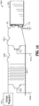
- FIGS. 14-16 Aspects of safety cut-off circuits for use with powered surgical instruments such as the surgical tack applier described above are illustrated in FIGS. 14-16 and described in detail below. It is contemplated that the safety cut-off circuits of the disclosure are incorporated into the housing of the powered surgical instruments and may utilize a shared power supply with that of the powered surgical instrument or may include its own independent power supply. Although the safety cut-off circuits are described as including certain components, it is understood that aspects of the safety cut-off circuits may include some or all of the components described, as needed for any specific implementation. In aspects, the safety cut-off circuits described below are configured to electrically couple to other electrical components of the powered surgical instrument, and additionally or alternatively, may be controlled by microprocessors of the powered surgical instrument.
- FIG. 14 illustrates a safety cut-off circuit 1400 which provides power cut-off when liquid is detected in the circuit to protect the electrical components of the surgical instrument.
- Safety cut-off circuit 1400 includes a power supply 1401, a fuse 1407, a liquid detection circuit 1411, and a voltage regulator 1409.
- the power supply 1401 includes a positive terminal 1403 and a negative terminal 1405 with the negative terminal 1405 being grounded, for example, to a chassis of a surgical instrument.
- the fuse 1407 is coupled in series to the positive terminal 1403 of the power supply 1401.
- the liquid detection circuit 1411 is coupled in parallel to the fuse 1407 and the negative terminal 1405 of the power supply 1401.
- the voltage regulator 1409 is operably coupled to the liquid detection circuit 1411 and the positive terminal 1403 of the power supply 1401 via the fuse 1407.
- the fuse 1407 includes an amperage rating greater than an amperage rating required to operate the safety cut-off circuit 1400.
- the liquid detection circuit 1411 may include water detection traces and/or an interlaced comb structure.
- first trace 1413 illustrated to the right of the liquid detection circuit 1411 in FIG. 14
- second trace 1415 illustrated to the left of liquid detection circuit 1411 in FIG. 14
- the liquid detection circuit 1411 is disposed upstream of any components required to establish logic on the board or in the surgical instrument. Disabling fuse 1407 cuts power to any microcontroller and all other circuitry components on the board or in the surgical instrument.
- FIG. 15 illustrates a safety cut-off circuit 1500 similar to safety cut-off circuit 1400 and only the differences between the two will be described for brevity. While safety cut-off circuit 1400 is useful for preventing damage to the components of the surgical instrument when liquid is detected in the circuit, safety cut-off circuit 1500 is configured to cut-off the power supply 1501 upon the occurrence of other safety-related conditions.
- safety cut-off circuit 1500 includes a transistor 1513 coupled in parallel to the safety cut-off circuit 1500 which is configured to be selectively triggered to create a short circuit and blow the fuse 1507.
- the amperage capacity of the transistor 1513 is higher than an amperage capacity of the fuse 1507 to ensure that the fuse 1507 will blow before any damage is incurred on the transistor 1513 or any other components of the circuit and surgical instrument.
- the transistor 1513 of the safety cut-off circuit 1500 includes a logic pin 1513a coupled to a microcontroller for selectively triggering the transistor 1513 to create the short circuit and blow the fuse 1507.
- the transistor 1513 is triggered to create the short circuit and blow the fuse 1507 when an end of useable life of the surgical instrument is detected, for example, for single use devices, upon completion of use of the surgical instrument.
- transistor 1513 is triggered to create the short circuit when liquid is detected elsewhere in the surgical instrument, not local to the liquid detection circuit 1511.
- transistor 1513 may also be triggered by a microcontroller to blow fuse 1507.
- FIG. 16 illustrates another aspect of a safety cut-off circuit 1600 similar to safety cut-off circuit 1400 and safety cut-off circuit 1500 described above.
- Safety cut-off circuit 1600 provides power cut-off when liquid is detected in the circuit to protect the electrical components of the surgical instrument and also includes a first transistor 1613 and a second transistor 1615 for selectively cutting off portions of the circuit.
- Safety cut-off circuit 1600 includes a power supply 1601, a fuse 1607a, a resettable fuse 1607b, a liquid detection circuit 1611, a first transistor 1613, a second transistor 1615, and a voltage regulator 1409.
- the power supply 1601 includes a positive terminal 1603 and a negative terminal 1605 with the negative terminal 1605 being grounded, for example, to a chassis of a surgical instrument.
- the fuse 1607a is coupled in series to the positive terminal 1603 of the power supply 1601 and the resettable fuse 1607b is coupled in series with the fuse 1607a.
- the first transistor 1613 is coupled in parallel, between the fuse 1607a and the resettable fuse 1607b.
- the liquid detection circuit 1611 is coupled in parallel to the resettable fuse 1607b and the negative terminal 1605 of the power supply 1601.
- the second transistor 1615 is coupled in parallel after the liquid detection circuit 1611.
- the voltage regulator 1609 is operably coupled to the liquid detection circuit 1611 and the positive terminal 1603 of the power supply 1601 via the fuse 1607a and the resettable fuse 1607b.
- the liquid detection circuit 1411 may include water detection traces and/or an interlaced comb structure.
- the fuse 1607a and/or resettable fuse 1607b includes an amperage rating greater than an amperage rating required to operate the safety cut-off circuit 1600. Additionally, an amperage rating of the resettable fuse 1607b is less than an amperage rating of the fuse 1607a, such that the resettable fuse 1607b will blow before the fuse 1607a blows, or without the fuse 1607a blowing at all. Additionally, an amperage capacity of the first transistor 1613 is greater than an amperage capacity of the fuse 1607a and an amperage capacity of the second transistor 1615 is greater than an amperage capacity of the resettable fuse 1607b.
- the first transistor 1613 includes a logic pin 1613a coupled to a microcontroller for selectively triggering the first transistor 1613 to create a short circuit and blow the fuse 1607a. Such an occurrence will permanently disable the safety cut-off circuit and protect the components of the surgical instrument.
- the second transistor 1615 includes a logic pin 1615a coupled to a microcontroller for selectively triggering the second transistor 1615 to create a short circuit and blow the resettable fuse 1607b. Such an occurrence of blowing the resettable fuse 1607b via the second transistor 1615 does not impact the fuse 1607a, and only temporarily disables the operation of the safety cut-off circuit 1600. Upon resetting the resettable fuse 1607b, the safety cut-off circuit 1600 functions normally.
- power supplied to the voltage regulator 1609 is cut off when liquid comes into contact with the liquid detection circuit 1611, when first transistor 1613 is caused to blow fuse 1607a, or when second transistor 1615 is caused to blow resettable fuse 1607b.
- the power supply 1601 becomes short circuited due to detection of liquid by liquid detection circuit 1611. This creates a very high current draw in excess of what is required to operate the surgical instrument or circuit normally and causes fuse 1607a and/or resettable fuse 1607b to blow.
- Safety cut-off circuit includes two additional components for disabling power.
- microcontroller logic can selectively trigger a transistor (e.g., first transistor 1613 or second transistor 1615) on the board that creates a short circuit to blow resettable fuse 1607b, to temporarily remove power, or blow fuse 1607a, to permanently remove power.
- the microcontroller could be programmed to do this for any number of reasons.
- the first transistor 1613 or second transistor 1615 can be triggered by microcontroller to create the short circuit and blow the fuse 1607a and/or the resettable fuse 1607b when an end of useable life of the surgical instrument is detected, for example, for single use devices, upon completion of use of the surgical instrument.
- the first transistor 1613 and/or the second transistor 1615 is triggered to create the short circuit when liquid is detected elsewhere in the surgical instrument, not local to the liquid detection circuit 1611. Additionally or alternatively, when erroneous behavior or signals are detected from another component of the surgical instrument (e.g., another circuit in the surgical instrument, a motor, a power source, etc.), the first transistor 1613 may also be triggered by a microcontroller to blow fuse 1607a and/or the second transistor 1615 may be triggered by a microcontroller to blow resettable fuse 1607b.
- another component of the surgical instrument e.g., another circuit in the surgical instrument, a motor, a power source, etc.
- the described techniques may be implemented in hardware, software, firmware, or any combination thereof. If implemented in software, the functions may be stored as one or more instructions or code on a computer-readable medium and executed by a hardware-based processing unit.
- Computer-readable media may include non-transitory computer-readable media, which corresponds to a tangible medium such as data storage media (e.g., RAM, ROM, EEPROM, flash memory, or any other medium that can be used to store desired program code in the form of instructions or data structures and that can be accessed by a computer).
- processors such as one or more digital signal processors (DSPs), general purpose microprocessors, application specific integrated circuits (ASICs), field programmable logic arrays (FPGAs), or other equivalent integrated or discrete logic circuitry.
- DSPs digital signal processors
- ASICs application specific integrated circuits
- FPGAs field programmable logic arrays
- processors may refer to any of the foregoing structure or any other physical structure suitable for implementation of the described techniques. Also, the techniques could be fully implemented in one or more circuits or logic elements.
Landscapes
- Health & Medical Sciences (AREA)
- Surgery (AREA)
- Life Sciences & Earth Sciences (AREA)
- Engineering & Computer Science (AREA)
- General Health & Medical Sciences (AREA)
- Biomedical Technology (AREA)
- Heart & Thoracic Surgery (AREA)
- Medical Informatics (AREA)
- Molecular Biology (AREA)
- Animal Behavior & Ethology (AREA)
- Nuclear Medicine, Radiotherapy & Molecular Imaging (AREA)
- Public Health (AREA)
- Veterinary Medicine (AREA)
- Chemical & Material Sciences (AREA)
- Chemical Kinetics & Catalysis (AREA)
- Electrochemistry (AREA)
- General Chemical & Material Sciences (AREA)
- Manufacturing & Machinery (AREA)
- Physics & Mathematics (AREA)
- Plasma & Fusion (AREA)
- Otolaryngology (AREA)
- Microelectronics & Electronic Packaging (AREA)
- Surgical Instruments (AREA)
Abstract
Description
- The present application claims the benefit of and priority to
U.S. Provisional Application Serial No. 62/945,951, filed on December 10, 2019 - The disclosure relates to surgical instruments and, more particularly, to a safety cut-off circuit and a powered surgical tack applier instrument including a safety cut-off circuit.
- Various surgical procedures require instruments capable of applying fasteners to tissue to form tissue connections or to secure objects to tissue. For example, during hernia repair it is often desirable to fasten a mesh to tissue. In certain hernias, such as direct or indirect inguinal hernias, a part of the intestine protrudes through a defect in the abdominal wall to form a hernial sac. The defect may be repaired using an open surgery procedure in which a relatively large incision is made and the hernia is closed outside the abdominal wall by suturing. The mesh is attached with sutures over the opening in the abdominal wall to provide reinforcement. However, this may also be accomplished through the use of minimally invasive surgical fasteners such as, e.g., surgical tacks.
- Following the surgical procedure, some surgical instruments may be reprocessed for reuse, while others are disposable.
- The disclosure relates to surgical instruments and, more particularly, to a safety cut-off circuit and a powered surgical tack applier instrument including a safety cut-off circuit.
- In accordance with an aspect, a safety cut-off circuit for a surgical instrument includes a positive terminal and a negative terminal, the negative terminal being grounded, a fuse coupled in series to the positive terminal of the power supply, a liquid detection circuit coupled in parallel to the fuse and the negative terminal of the power supply, and a voltage regulator operably coupled to the liquid detection circuit and the positive terminal of the power supply via the fuse. Power supplied to the voltage regulator is cut-off when liquid comes into contact with the liquid detection circuit.
- The fuse is configured to blow when liquid contacts the liquid detection circuit. In an aspect, the fuse includes an amperage rating greater than an amperage rating required to operate the safety cut-off circuit.
- In an aspect, the liquid detection circuit is coupled to the fuse via a first trace and to the voltage regulator via a second trace and the first trace is of a lower gauge relative to the second trace.
- In an aspect, the liquid detection circuit includes water detection traces. In an aspect, the liquid detection circuit includes an interlaced comb structure.
- In an aspect, the safety cut-off circuit includes a transistor coupled in parallel to the safety cut-off circuit and configured to be selectively triggered to create a short circuit and blow the fuse. An amperage capacity of the transistor may be higher than an amperage capacity of the fuse. In an aspect, the transistor includes a logic pin coupled to a microcontroller for selectively triggering the transistor to create the short circuit and blow the fuse. The transistor may be triggered to create the short circuit and blow the fuse when at least one of an end of useable life is detected, liquid is detected elsewhere in the surgical instrument remote from the liquid detection circuit, or erroneous behavior or signals are detected from at least one other electrical component of the surgical instrument. The at least one other electrical component may include a motor or a power source.
- In an aspect, the safety cut-off circuit includes a resettable fuse coupled in series to the fuse, wherein an amperage rating of the resettable fuse is less than an amperage rating of the fuse. The safety cut-off circuit may further include a first transistor and a second transistor, wherein an amperage capacity of the first transistor is greater than an amperage capacity of the fuse and an amperage capacity of the second transistor is greater than an amperage capacity of the resettable fuse. In an aspect, the second transistor includes a logic pin coupled to a microcontroller for selectively triggering the second transistor to create a short circuit and blow the resettable fuse.
- In another aspect of the disclosure, a safety cut-off circuit for a surgical instrument includes a power supply including a positive terminal and a negative terminal, the negative terminal being grounded, a fuse coupled in series to the positive terminal of the power supply, at least one of a liquid detection circuit or a transistor coupled in parallel to the fuse and the negative terminal of the power supply, a voltage regulator operably coupled to at least one of the liquid detection circuit or the transistor and the positive terminal of the power supply via the fuse. Power supplied to the voltage regulator is cut-off when at least one of liquid comes into contact with the liquid detection circuit or the transistor is caused to short circuit the safety cut-off circuit and blow the fuse.
- In yet another aspect of the disclosure, a powered surgical instrument includes a handle assembly, an articulation lever assembly, an elongate member, and a safety cut-off circuit operably coupled to at least one of the handle assembly, the articulation lever assembly, or the elongate member. The handle assembly includes an actuation assembly including a motor, an actuation rod having a first end operatively coupled to an output shaft of the motor for concomitant rotation therewith, and an actuation switch configured to actuate the motor. The articulation lever assembly includes an articulation rod and an articulation lever operatively coupled with the articulation rod. The safety cut-off circuit includes a power supply including a positive terminal and a negative terminal, the negative terminal being grounded, a fuse coupled in series to the positive terminal of the power supply, a liquid detection circuit coupled in parallel to the fuse and the negative terminal of the power supply, and a voltage regulator operably coupled to the liquid detection circuit and the positive terminal of the power supply via the fuse. Power supplied to the voltage regulator is cut-off when liquid comes into contact with the liquid detection circuit.
- The details of one or more aspects of the disclosure are set forth in the accompanying drawings and the description below. Other features, objects, and advantages of the techniques described in this disclosure will be apparent from the description and drawings, and from the claims.
- Various aspects of the disclosure are described hereinbelow with reference to the drawings, which are incorporated and constitute a part of this specification, wherein:
-
FIG. 1 is a perspective view of a handle assembly of a powered surgical tack applier in accordance with an aspect of the disclosure; -
FIG. 2 is a partial perspective view of an elongate member of the powered surgical tack applier; -
FIG. 3 is a partial perspective view of a loading unit of the surgical tack applier ofFIG. 1 , illustrating a coil separated from an inner tube; -
FIG. 4 is a longitudinal, cross-sectional view of a distal end of the powered surgical tack applier, illustrating implanting of a surgical tack into underlying tissue through a surgical mesh; -
FIG. 5 is a perspective view of a surgical mesh for use with the powered surgical tack applier ofFIG. 1 , illustrating anchoring the surgical mesh to underlying tissue with a plurality of surgical tacks; -
FIG. 6 is a side view of the handle assembly ofFIG. 1 with a half of a housing removed; -
FIG. 7 is an exploded perspective view of the handle assembly ofFIG. 1 with parts separated; -
FIG. 8 is a partial side view of the handle assembly ofFIG. 1 ; -
FIG. 9 is a partial side view of the handle assembly ofFIG. 1 with a portion of the housing removed; -
FIG. 10 is a partial perspective view of the handle assembly ofFIG. 1 , illustrating an actuation assembly; -
FIG. 11 is a perspective view of a handle assembly for use with a powered surgical tack applier in accordance with another aspect of the disclosure; -
FIG. 12 is a perspective view of the handle assembly ofFIG. 11 with a half of the housing removed; -
FIG. 13 is a side view of the handle assembly ofFIG. 11 ; -
FIG. 14 is a circuit diagram of a safety cut-off circuit for a powered surgical instrument in accordance with an aspect of the disclosure; -
FIG. 15 is a circuit diagram of a safety cut-off circuit for a powered surgical instrument in accordance with an aspect of the disclosure; and -
FIG. 16 is a circuit diagram of a safety cut-off circuit for a powered surgical instrument in accordance with an aspect of the disclosure. - Aspects of the disclosed surgical instrument and its components are described in detail with reference to the drawings, in which like reference numerals designate identical or corresponding elements in each of the several views. As used herein, the term "distal," as is conventional, will refer to that portion of the instrument, apparatus, device, or component thereof which is farther from the user, while the term "proximal" will refer to that portion of the instrument, apparatus, device, or component thereof which is closer to the user. In the following description, well-known functions or constructions are not described in detail to avoid obscuring the disclosure in unnecessary detail.
- In electrically powered laparoscopic surgical devices, there often is a need to permanently disable electronic components due to an event occurring during a product's life. Manufacturers may choose to permanently disable electronics as a means of mitigating patient and surgeon hazard in the event of liquid ingress or to ensure that devices are not used beyond their known safe useful life. In both instances disabling the electronic components would allow the device to "fail safe."
- Following the surgical procedure, some surgical instruments may be reprocessed for reuse, while others are disposed of. A need exists for disabling surgical instruments that are to be disposed of in order to inhibit their reuse beyond their useful life and for ensuring the safety of the clinician and patient in the event of a faulty condition.
- This disclosure provides electronic solutions to address the above-noted concerns. Multiple aspects using either liquid detection circuits (e.g., interlaced comb circuits) or one or more transistors to create short circuits combined with board-mounted fuses are described. The use of passive components that fail due to liquid ingress or other fault conditions ensures that if the microcontroller logic of the surgical instrument or signals become compromised, the device will still safely be able to turn itself off.
- With reference to
FIGS. 1-4 , a handle assembly for use with a surgical tack applier for applying asurgical tack 10 suitable for insertion through a surgical mesh "M" and tissue "T" is shown generally as ahandle assembly 200. The surgical tack applier generally includes thehandle assembly 200, anelongate member 50 having anarticulation portion 60, and aloading unit 30 selectably connectable to a distal end of theelongate member 50. Theloading unit 30 is electro-mechanically coupled to thehandle assembly 200 and supports a plurality ofsurgical tacks 10. - The
loading unit 30 includes anouter tube 32 defining a lumen (not shown), a spiral orcoil 36 fixedly disposed within theouter tube 32, and aninner tube 38 rotatably disposed within thecoil 36. Theinner tube 38 defines a lumen therethrough, and includes afirst portion 38a and a splinedsecond portion 38b. Thesecond portion 38b of theinner tube 38 is slotted, defining a pair of tines 38bi and a pair ofchannels 38b2. Thesecond portion 38b of theinner tube 38 is configured to support the plurality ofsurgical tacks 10 within theinner tube 38. In particular, thesurgical tacks 10 are loaded into theloading unit 30 such that the pair of opposing threadedsections 112a of thesurgical tacks 10 extend throughrespective channels 38b2 of thesecond portion 38b of theinner tube 38 and are slidably disposed within the groove of thecoil 36, and the pair of tines 38bi of thesecond portion 38b of theinner tube 38 are disposed within the pair of slottedsections 116a of thesurgical tack 10. In use, as theinner tube 38 is rotated about a longitudinal axis "X-X" thereof, relative to thecoil 36, the pair of tines 38bi of theinner tube 38 transmits the rotation to thesurgical tacks 10 and advance thesurgical tacks 10 distally as thehead threads 114a of thesurgical tacks 10 engage with thecoil 36. - With particular respect to
FIG. 2 , the surgical tack applier includes anarticulation portion 60 operatively coupled with an articulation lever assembly 300 (FIG. 6 ) supported in thehandle assembly 200. Thearticulation portion 60 may include a drive assembly (not shown) having a slidable tube and an articulation arm pivotally coupled to the slidable tube. Thearticulation lever assembly 300 is coupled to the slidable tube so that when thearticulation lever assembly 300 is actuated the slidable tube is displaced through theelongated member 50. Longitudinal translation of the slidable tube moves the articulation arm to enable theloading unit 30 to articulate relative to the longitudinal axis "X-X" (FIG. 3 ). - With reference now to
FIG. 6 , thehandle assembly 200 includes ahousing 202, anarticulation lever assembly 300 configured to articulate the articulation portion 60 (FIG. 2 ) of theelongate member 50, anactuation assembly 400 configured to eject thesurgical tack 10 out of theloading unit 30 of theelongate member 50, and abattery pack 440 removably attached to thehousing 202. Thehousing 202 includes an ergonomic structure providing comfort, ease of use, and intuitiveness such that when thehousing 202 is gripped by a clinician, e.g., a thumb, may be positioned to slide thearticulation lever assembly 300 and, e.g., an index finger, may be positioned to trigger anactuation switch 404 of theactuation assembly 400. Actuation of theactuation assembly 400 ejects a surgical tack 10 (FIG. 4 ) out of theloading unit 30 through mesh "M" (FIG. 4 ) and into body tissue "T". - With reference to
FIGS. 6 and7 , thearticulation lever assembly 300 includes anarticulation rod 310 andarticulation lever 360 operatively coupled with thearticulation rod 310. Thearticulation rod 310 is operatively coupled with the articulation portion 60 (FIG. 2 ) of theelongate member 50 of the surgical tack applier. Thearticulation rod 310 is slidably supported on thehousing 202 of thehandle assembly 200 by a mountingplate 312 defining a channel 304 (FIG. 8 ) configured to enable axial displacement of thearticulation rod 310 therethrough, which, causes articulation of the articulation portion 60 (FIG. 2 ) based on the axial position of thearticulation rod 310. In particular, thearticulation rod 310 has an annular structure defining a channel 317 (FIG. 8 ) dimensioned to receive theactuation rod 402 of theactuation assembly 400 therein. Thearticulation rod 310 further defines atransverse bore 314 dimensioned to receive anarticulation drive pin 316 coupled with thearticulation lever 360. - With continued reference to
FIGS. 6 and7 , thearticulation lever 360 includes ahousing portion 362 and an engagingportion 364 slidably engaging anengaging surface 204 of thehousing 202. Theengaging surface 204 has an arcuate profile enabling the engagingportion 364 to travel in, e.g., an arc. Thehousing portion 362 is disposed within thehousing 202 and is dimensioned to receivearticulation pivot arms member 368 therebetween. Eacharticulation pivot arm first bore 370a, 370b, asecond bore slot first bores 370a, 370b are dimensioned to receive an articulation pivot pin 378 (FIG. 8 ) pivotably coupling thearticulation pivot arms housing 202. Thesecond bores articulation drive pin 316 extending through thetransverse bore 314 of thearticulation rod 310. Under such a configuration, when thearticulation pivot arms articulation pivot pin 378, thearticulation drive pin 316 causes axial displacement of thearticulation rod 310. Thearticulation drive pin 316 defines atransverse bore 380 dimensioned to receive theactuation rod 402 of theactuation assembly 400 therethrough. Theslots articulation pivot arms cam pin 384 biased away from thearticulation pivot pin 378 by a biasingmember 368 interposed between thearticulation pivot arms - With reference now to
FIGS. 7 and 8 , thehousing portion 362 of thearticulation lever 360 is dimensioned to receive the matedarticulation pivot arms housing portion 362 defines aslot 363 dimensioned to cammingly receive thecam pin 384 which is cammingly slidable in theslots articulation pivot arms housing portion 362 includes atooth 367 configured to engage adetent portion 208 of thehousing 202 to inhibit movement of thearticulation lever 360 relative to thehousing 202, thereby locking an axial position of thearticulation rod 310, which, in turn, locks the orientation of the articulation portion 60 (FIG. 2 ) of the surgical tack applier. Under such a configuration, thearticulation lever 360 is biased away from thearticulation pivot pin 378 such that thetooth 367 of thehousing portion 362 engages thedetent portion 208. When the engagingportion 364 of thearticulation lever 360 is depressed towards thehousing 202, thetooth 367 is moved away from thedetent portion 208 enabling the clinician to slidably move the engagingportion 364 on the engaging surface 204 (FIG. 6 ) of thehousing 202, thereby enabling articulation of thearticulation portion 60 of the surgical tack applier to a desired orientation. - With reference now to
FIG. 9 thearticulation lever assembly 300 further includes acam wedge 350 having first, second, andthird portions cam pin 384 which is cammingly slidable in theslots articulation pivot arms slot 363 of thearticulation lever 360. The first, second, andthird portions respective detent sections detent portion 208. In this manner, articulation backlash is reduced as thecam pin 384 rides along the first, second, andthird portions cam wedge 350. - With reference back to
FIGS. 6 and7 , theactuation assembly 400 includes anactuation rod 402 operatively coupled with the loading unit 30 (FIG. 2 ) of the surgical tack applier, amotor 420, anactuation switch 404 configured to actuate themotor 420 to eject the surgical tacks 10 (FIG. 4 ), a printedcircuit board 430 including a microprocessor (not shown) to control theactuation assembly 400, and abattery pack 440 removably attached to thehousing 202 and electrically connected to themotor 420 and the printedcircuit board 430. A proximal end of theactuation rod 402 is operatively coupled with an output shaft of themotor 420 for concomitant rotation therewith such that when theactuation switch 404 is triggered by the clinician, themotor 420 is actuated to impart axial rotation to theactuation rod 402. A distal end of theactuation rod 402 is operatively coupled with the inner tube 38 (FIG. 3 ) of theloading unit 30 for concomitant rotation therewith. - With reference now to
FIG. 10 , theactuation assembly 400 may further include anencoder assembly 410 operatively connected to theactuation rod 402 and the processor of the printedcircuit board 430. Theencoder assembly 410 may include, e.g., an optical,motor encoder 405 configured to keep an accurate count of turns of the motor output shaft or theactuation rod 402 to ensure a proper number of turns are made to insert thesurgical tack 10 through, e.g., the mesh "M", and into tissue "T" (FIG. 4 ). In addition, theencoder assembly 410 may further include, e.g., a single notched,encoder wheel 407 configured to ensure correct clocking of a distal end of theactuation rod 402 relative to the loading unit 30 (FIG. 2 ). Theencoder assembly 410 may further include a light emitting diode ("LED")indicator 409 to indicate status of the ejection of eachsurgical tack 10. For example, a green light may indicate proper application of thesurgical tack 10 through the mesh "M" and into tissue "T", and a red light may indicate, e.g., improper application of thesurgical tack 10, due to an error signal from theoptical motor encoder 405 or the single notchedencoder wheel 407. Alternatively, theencoder assembly 410 may further include a piezoelectric element 411 (FIG. 6 ) for providing an audible tone for proper application of thesurgical tack 10. - With brief reference to
FIG. 6 , thehandle assembly 200 may further include arelease lever 450 slidably attached to thehousing 202. Therelease lever 450 is operatively coupled with the loading unit 30 (FIG. 2 ) such that when therelease lever 450 is pulled, theloading unit 30 is detached from the elongate member 50 (FIG. 2 ) of the surgical tack applier. - In use, the
loading unit 30 is operatively mounted to a distal end of theelongate member 50. Theloading unit 30 is introduced into a target surgical site while in the non-articulated condition. The clinician may remotely articulateloading unit 30 relative the longitudinal axis "X-X" to access the surgical site. Specifically, the clinician may slide the engagingportion 364 of thearticulation lever 360 along the engagingsurface 204 of thehousing 202. As thearticulation rod 310 is displaced axially, theloading unit 30 is moved to an articulated orientation relative to the central longitudinal axis "X-X". Furthermore, the clinician may position the surgical mesh "M" adjacent the surgical site. Once the surgical mesh "M" is properly positioned on the surgical site, the clinician may trigger theactuation switch 404 to eject asurgical tack 10 through the mesh "M" and into tissue "T". While thearticulation rod 310 is configured for axial displacement, it is further contemplated that anactuation rod 1310 may be rotatably supported by arotor 1370 such that theactuation rod 1310 outputs an axial rotation which may be utilized by theloading unit 30 to effect articulation thereof, as can be appreciated with reference toFIGS. 11-13 . It is further contemplated that theactuation assembly 400 may further include a transmission assembly to selectively impart rotation of the output shaft of themotor 420 to theactuation rod 1310. - Aspects of safety cut-off circuits for use with powered surgical instruments such as the surgical tack applier described above are illustrated in
FIGS. 14-16 and described in detail below. It is contemplated that the safety cut-off circuits of the disclosure are incorporated into the housing of the powered surgical instruments and may utilize a shared power supply with that of the powered surgical instrument or may include its own independent power supply. Although the safety cut-off circuits are described as including certain components, it is understood that aspects of the safety cut-off circuits may include some or all of the components described, as needed for any specific implementation. In aspects, the safety cut-off circuits described below are configured to electrically couple to other electrical components of the powered surgical instrument, and additionally or alternatively, may be controlled by microprocessors of the powered surgical instrument. -
FIG. 14 illustrates a safety cut-off circuit 1400 which provides power cut-off when liquid is detected in the circuit to protect the electrical components of the surgical instrument. Safety cut-off circuit 1400 includes apower supply 1401, afuse 1407, aliquid detection circuit 1411, and avoltage regulator 1409. Thepower supply 1401 includes apositive terminal 1403 and a negative terminal 1405 with the negative terminal 1405 being grounded, for example, to a chassis of a surgical instrument. Thefuse 1407 is coupled in series to thepositive terminal 1403 of thepower supply 1401. Theliquid detection circuit 1411 is coupled in parallel to thefuse 1407 and thenegative terminal 1405 of thepower supply 1401. Thevoltage regulator 1409 is operably coupled to theliquid detection circuit 1411 and thepositive terminal 1403 of thepower supply 1401 via thefuse 1407. - The
fuse 1407 includes an amperage rating greater than an amperage rating required to operate the safety cut-off circuit 1400. Theliquid detection circuit 1411 may include water detection traces and/or an interlaced comb structure. - During operation, power supplied to the
voltage regulator 1409 is cut off when liquid comes into contact with theliquid detection circuit 1411. In particular, in the event of water or other liquid ingress into the surgical instrument that could corrupt the logic and signals of the microcontroller or other component of the surgical instrument, thepower supply 1401 becomes short circuited due to detection of liquid byliquid detection circuit 1411. This creates a very high current draw in excess of what is required to operate the surgical instrument or circuit normally and causes fuse 1407 to blow. In aspects,first trace 1413, illustrated to the right of theliquid detection circuit 1411 inFIG. 14 , is of a lower gauge value thansecond trace 1415, illustrated to the left ofliquid detection circuit 1411 inFIG. 14 , such that thefirst trace 1413 is large enough to handle the required current to blow thefuse 1407. As illustrated inFIG. 14 , theliquid detection circuit 1411 is disposed upstream of any components required to establish logic on the board or in the surgical instrument. Disablingfuse 1407 cuts power to any microcontroller and all other circuitry components on the board or in the surgical instrument. -
FIG. 15 illustrates a safety cut-off circuit 1500 similar to safety cut-off circuit 1400 and only the differences between the two will be described for brevity. While safety cut-off circuit 1400 is useful for preventing damage to the components of the surgical instrument when liquid is detected in the circuit, safety cut-off circuit 1500 is configured to cut-off thepower supply 1501 upon the occurrence of other safety-related conditions. - Unlike safety cut-
off circuit 1400, theliquid detection circuit 1511 of safety cut-off circuit 1500 is optional and may be removed from the circuit. Additionally, safety cut-off circuit 1500 includes atransistor 1513 coupled in parallel to the safety cut-off circuit 1500 which is configured to be selectively triggered to create a short circuit and blow thefuse 1507. The amperage capacity of thetransistor 1513 is higher than an amperage capacity of thefuse 1507 to ensure that thefuse 1507 will blow before any damage is incurred on thetransistor 1513 or any other components of the circuit and surgical instrument. - The
transistor 1513 of the safety cut-off circuit 1500 includes alogic pin 1513a coupled to a microcontroller for selectively triggering thetransistor 1513 to create the short circuit and blow thefuse 1507. Thetransistor 1513 is triggered to create the short circuit and blow thefuse 1507 when an end of useable life of the surgical instrument is detected, for example, for single use devices, upon completion of use of the surgical instrument. In an aspect,transistor 1513 is triggered to create the short circuit when liquid is detected elsewhere in the surgical instrument, not local to theliquid detection circuit 1511. Additionally or alternatively, when erroneous behavior or signals are detected from another component of the surgical instrument (e.g., another circuit in the surgical instrument, a motor, a power source, etc.),transistor 1513 may also be triggered by a microcontroller to blowfuse 1507. -
FIG. 16 illustrates another aspect of a safety cut-off circuit 1600 similar to safety cut-off circuit 1400 and safety cut-off circuit 1500 described above. Safety cut-off circuit 1600 provides power cut-off when liquid is detected in the circuit to protect the electrical components of the surgical instrument and also includes afirst transistor 1613 and asecond transistor 1615 for selectively cutting off portions of the circuit. - Safety cut-
off circuit 1600 includes apower supply 1601, afuse 1607a, aresettable fuse 1607b, aliquid detection circuit 1611, afirst transistor 1613, asecond transistor 1615, and avoltage regulator 1409. Thepower supply 1601 includes apositive terminal 1603 and a negative terminal 1605 with the negative terminal 1605 being grounded, for example, to a chassis of a surgical instrument. Thefuse 1607a is coupled in series to thepositive terminal 1603 of thepower supply 1601 and theresettable fuse 1607b is coupled in series with thefuse 1607a. Thefirst transistor 1613 is coupled in parallel, between thefuse 1607a and theresettable fuse 1607b. Theliquid detection circuit 1611 is coupled in parallel to theresettable fuse 1607b and thenegative terminal 1605 of thepower supply 1601. Thesecond transistor 1615 is coupled in parallel after theliquid detection circuit 1611. Thevoltage regulator 1609 is operably coupled to theliquid detection circuit 1611 and thepositive terminal 1603 of thepower supply 1601 via thefuse 1607a and theresettable fuse 1607b. - The
liquid detection circuit 1411 may include water detection traces and/or an interlaced comb structure. Thefuse 1607a and/orresettable fuse 1607b includes an amperage rating greater than an amperage rating required to operate the safety cut-off circuit 1600. Additionally, an amperage rating of theresettable fuse 1607b is less than an amperage rating of thefuse 1607a, such that theresettable fuse 1607b will blow before thefuse 1607a blows, or without thefuse 1607a blowing at all. Additionally, an amperage capacity of thefirst transistor 1613 is greater than an amperage capacity of thefuse 1607a and an amperage capacity of thesecond transistor 1615 is greater than an amperage capacity of theresettable fuse 1607b. - The
first transistor 1613 includes alogic pin 1613a coupled to a microcontroller for selectively triggering thefirst transistor 1613 to create a short circuit and blow thefuse 1607a. Such an occurrence will permanently disable the safety cut-off circuit and protect the components of the surgical instrument. Thesecond transistor 1615 includes alogic pin 1615a coupled to a microcontroller for selectively triggering thesecond transistor 1615 to create a short circuit and blow theresettable fuse 1607b. Such an occurrence of blowing theresettable fuse 1607b via thesecond transistor 1615 does not impact thefuse 1607a, and only temporarily disables the operation of the safety cut-off circuit 1600. Upon resetting theresettable fuse 1607b, the safety cut-off circuit 1600 functions normally. - During operation, power supplied to the
voltage regulator 1609 is cut off when liquid comes into contact with theliquid detection circuit 1611, whenfirst transistor 1613 is caused to blowfuse 1607a, or whensecond transistor 1615 is caused to blowresettable fuse 1607b. In particular, in the event of water or other liquid ingress into the surgical instrument that could corrupt the logic and signals of the microcontroller or other component of the surgical instrument, thepower supply 1601 becomes short circuited due to detection of liquid byliquid detection circuit 1611. This creates a very high current draw in excess of what is required to operate the surgical instrument or circuit normally and causes fuse 1607a and/orresettable fuse 1607b to blow. - Safety cut-off circuit includes two additional components for disabling power. As described above, microcontroller logic can selectively trigger a transistor (e.g.,
first transistor 1613 or second transistor 1615) on the board that creates a short circuit to blowresettable fuse 1607b, to temporarily remove power, or blowfuse 1607a, to permanently remove power. The microcontroller could be programmed to do this for any number of reasons. Thefirst transistor 1613 orsecond transistor 1615 can be triggered by microcontroller to create the short circuit and blow thefuse 1607a and/or theresettable fuse 1607b when an end of useable life of the surgical instrument is detected, for example, for single use devices, upon completion of use of the surgical instrument. In an aspect, thefirst transistor 1613 and/or thesecond transistor 1615 is triggered to create the short circuit when liquid is detected elsewhere in the surgical instrument, not local to theliquid detection circuit 1611. Additionally or alternatively, when erroneous behavior or signals are detected from another component of the surgical instrument (e.g., another circuit in the surgical instrument, a motor, a power source, etc.), thefirst transistor 1613 may also be triggered by a microcontroller to blowfuse 1607a and/or thesecond transistor 1615 may be triggered by a microcontroller to blowresettable fuse 1607b. - Persons skilled in the art will understand that the structures and methods specifically described herein and shown in the accompanying figures are non-limiting exemplary aspects, and that the description, disclosure, and figures should be construed merely as exemplary of particular aspects. It is to be understood, therefore, that the disclosure is not limited to the precise aspects described, and that various other changes and modifications may be effected by one skilled in the art without departing from the scope or spirit of the disclosure.
- Additionally, the elements and features shown or described in connection with certain aspects may be combined with the elements and features of certain other aspects without departing from the scope of the disclosure, and that such modifications and variations are also included within the scope of the disclosure. Accordingly, the subject matter of the disclosure is not limited by what has been particularly shown and described.
- It should be understood that various aspects disclosed herein may be combined in different combinations than the combinations specifically presented in the description and accompanying drawings. It should also be understood that, depending on the example, certain acts or events of any of the processes or methods described herein may be performed in a different sequence, may be added, merged, or left out altogether (e.g., all described acts or events may not be necessary to carry out the techniques). In addition, while certain aspects of this disclosure are described as being performed by a single module or unit for purposes of clarity, it should be understood that the techniques of this disclosure may be performed by a combination of units or modules associated with, for example, a medical device.
- In one or more examples, the described techniques may be implemented in hardware, software, firmware, or any combination thereof. If implemented in software, the functions may be stored as one or more instructions or code on a computer-readable medium and executed by a hardware-based processing unit. Computer-readable media may include non-transitory computer-readable media, which corresponds to a tangible medium such as data storage media (e.g., RAM, ROM, EEPROM, flash memory, or any other medium that can be used to store desired program code in the form of instructions or data structures and that can be accessed by a computer).
- Instructions may be executed by one or more processors, such as one or more digital signal processors (DSPs), general purpose microprocessors, application specific integrated circuits (ASICs), field programmable logic arrays (FPGAs), or other equivalent integrated or discrete logic circuitry. Accordingly, the term "processor" as used herein may refer to any of the foregoing structure or any other physical structure suitable for implementation of the described techniques. Also, the techniques could be fully implemented in one or more circuits or logic elements.
- The invention may be described by reference to the following numbered paragraphs:-
- 1. A safety cut-off circuit for a surgical instrument, the safety cut-off circuit comprising:
- a power supply including a positive terminal and a negative terminal, the negative terminal being grounded;
- a fuse coupled in series to the positive terminal of the power supply;
- a liquid detection circuit coupled in parallel to the fuse and the negative terminal of the power supply; and
- a voltage regulator operably coupled to the liquid detection circuit and the positive terminal of the power supply via the fuse, wherein power supplied to the voltage regulator is cut-off when liquid comes into contact with the liquid detection circuit.
- 2. The safety cut-off circuit of paragraph 1, wherein the fuse is configured to blow when liquid contacts the liquid detection circuit.
- 3. The safety cut-off circuit of paragraph 1, wherein the liquid detection circuit is coupled to the fuse via a first trace and to the voltage regulator via a second trace and the first trace is of a lower gauge relative to the second trace.
- 4. The safety cut-off circuit of paragraph 1, wherein the liquid detection circuit includes water detection traces.
- 5. The safety cut-off circuit of paragraph 1, wherein the liquid detection circuit includes an interlaced comb structure.
- 6. The safety cut-off circuit of paragraph 1, wherein the fuse includes an amperage rating greater than an amperage rating required to operate the safety cut-off circuit.
- 7. The safety cut-off circuit of paragraph 1, further comprising a transistor coupled in parallel to the safety cut-off circuit and configured to be selectively triggered to create a short circuit and blow the fuse.
- 8. The safety cut-off circuit of paragraph 7, wherein an amperage capacity of the transistor is higher than an amperage capacity of the fuse.
- 9. The safety cut-off circuit of paragraph 7, wherein the transistor includes a logic pin coupled to a microcontroller for selectively triggering the transistor to create the short circuit and blow the fuse.
- 10. The safety cut-off circuit of paragraph 7, wherein the transistor is triggered to create the short circuit and blow the fuse when at least one of an end of useable life is detected, liquid is detected elsewhere in the surgical instrument remote from the liquid detection circuit, or erroneous behavior or signals are detected from at least one other electrical component of the surgical instrument.
- 11. The safety cut-off circuit of
paragraph 10, wherein the at least one other electrical component of the surgical instrument includes a motor or a power source. - 12. The safety cut-off circuit of paragraph 1, further comprising a resettable fuse coupled in series to the fuse, wherein an amperage rating of the resettable fuse is less than an amperage rating of the fuse.
- 13. The safety cut-off circuit of paragraph 12, further comprising a first transistor and a second transistor, wherein an amperage capacity of the first transistor is greater than an amperage capacity of the fuse and an amperage capacity of the second transistor is greater than an amperage capacity of the resettable fuse.
- 14. The safety cut-off circuit of paragraph 13, wherein the second transistor includes a logic pin coupled to a microcontroller for selectively triggering the second transistor to create a short circuit and blow the resettable fuse.
- 15. A safety cut-off circuit for a surgical instrument, the safety cut-off circuit comprising:
- a power supply including a positive terminal and a negative terminal, the negative terminal being grounded;
- a fuse coupled in series to the positive terminal of the power supply;
- at least one of a liquid detection circuit or a transistor coupled in parallel to the fuse and the negative terminal of the power supply; and
- a voltage regulator operably coupled to at least one of the liquid detection circuit or the transistor and the positive terminal of the power supply via the fuse, wherein power supplied to the voltage regulator is cut-off when at least one of liquid comes into contact with the liquid detection circuit or the transistor is caused to short circuit the safety cut-off circuit and blow the fuse.
- 16. A powered surgical instrument comprising:
- a handle assembly comprising:
- an actuation assembly including a motor;
- an actuation rod having a first end operatively coupled to an output shaft of the motor for concomitant rotation therewith; and
- an actuation switch configured to actuate the motor;
- an articulation lever assembly including an articulation rod and an articulation lever operatively coupled with the articulation rod;
- an elongate member extending distally from the handle assembly and including a loading unit having a plurality of surgical tacks; and
- a safety cut-off circuit operably coupled to at least one of the handle assembly, the articulation lever assembly, or the elongate member, the safety cut-off circuit comprising:
- a power supply including a positive terminal and a negative terminal, the negative terminal being grounded;
- a fuse coupled in series to the positive terminal of the power supply;
- a liquid detection circuit coupled in parallel to the fuse and the negative terminal of the power supply; and
- a voltage regulator operably coupled to the liquid detection circuit and the positive terminal of the power supply via the fuse, wherein power supplied to the voltage regulator is cut-off when liquid comes into contact with the liquid detection circuit.
- a handle assembly comprising:
Claims (15)
- A safety cut-off circuit for a surgical instrument, the safety cut-off circuit comprising:a power supply including a positive terminal and a negative terminal, the negative terminal being grounded;a fuse coupled in series to the positive terminal of the power supply;a liquid detection circuit coupled in parallel to the fuse and the negative terminal of the power supply; anda voltage regulator operably coupled to the liquid detection circuit and the positive terminal of the power supply via the fuse, wherein power supplied to the voltage regulator is cut-off when liquid comes into contact with the liquid detection circuit.
- The safety cut-off circuit of claim 1, wherein the fuse is configured to blow when liquid contacts the liquid detection circuit.
- The safety cut-off circuit of claim 1 or claim 2, wherein the liquid detection circuit is coupled to the fuse via a first trace and to the voltage regulator via a second trace and the first trace is of a lower gauge relative to the second trace.
- The safety cut-off circuit of any preceding claim, wherein the liquid detection circuit includes water detection traces.
- The safety cut-off circuit of any preceding claim, wherein the liquid detection circuit includes an interlaced comb structure.
- The safety cut-off circuit of any preceding claim, wherein the fuse includes an amperage rating greater than an amperage rating required to operate the safety cut-off circuit.
- The safety cut-off circuit of any preceding claim, further comprising a transistor coupled in parallel to the safety cut-off circuit and configured to be selectively triggered to create a short circuit and blow the fuse.
- The safety cut-off circuit of claim 7, wherein an amperage capacity of the transistor is higher than an amperage capacity of the fuse.
- The safety cut-off circuit of claim 7, wherein the transistor includes a logic pin coupled to a microcontroller for selectively triggering the transistor to create the short circuit and blow the fuse.
- The safety cut-off circuit of claim 7, wherein the transistor is triggered to create the short circuit and blow the fuse when at least one of an end of useable life is detected, liquid is detected elsewhere in the surgical instrument remote from the liquid detection circuit, or erroneous behavior or signals are detected from at least one other electrical component of the surgical instrument; preferably wherein the at least one other electrical component of the surgical instrument includes a motor or a power source.
- The safety cut-off circuit of any preceding claim, further comprising a resettable fuse coupled in series to the fuse, wherein an amperage rating of the resettable fuse is less than an amperage rating of the fuse.
- The safety cut-off circuit of claim 11, further comprising a first transistor and a second transistor, wherein an amperage capacity of the first transistor is greater than an amperage capacity of the fuse and an amperage capacity of the second transistor is greater than an amperage capacity of the resettable fuse.
- The safety cut-off circuit of claim 12, wherein the second transistor includes a logic pin coupled to a microcontroller for selectively triggering the second transistor to create a short circuit and blow the resettable fuse.
- A safety cut-off circuit for a surgical instrument, the safety cut-off circuit comprising:a power supply including a positive terminal and a negative terminal, the negative terminal being grounded;a fuse coupled in series to the positive terminal of the power supply;at least one of a liquid detection circuit or a transistor coupled in parallel to the fuse and the negative terminal of the power supply; anda voltage regulator operably coupled to at least one of the liquid detection circuit or the transistor and the positive terminal of the power supply via the fuse, wherein power supplied to the voltage regulator is cut-off when at least one of liquid comes into contact with the liquid detection circuit or the transistor is caused to short circuit the safety cut-off circuit and blow the fuse.
- A powered surgical instrument comprising:a handle assembly comprising:an actuation assembly including a motor;an actuation rod having a first end operatively coupled to an output shaft of the motor for concomitant rotation therewith; andan actuation switch configured to actuate the motor;an articulation lever assembly including an articulation rod and an articulation lever operatively coupled with the articulation rod;an elongate member extending distally from the handle assembly and including a loading unit having a plurality of surgical tacks; anda safety cut-off circuit operably coupled to at least one of the handle assembly, the articulation lever assembly, or the elongate member, the safety cut-off circuit comprising:a power supply including a positive terminal and a negative terminal, the negative terminal being grounded;a fuse coupled in series to the positive terminal of the power supply;a liquid detection circuit coupled in parallel to the fuse and the negative terminal of the power supply; anda voltage regulator operably coupled to the liquid detection circuit and the positive terminal of the power supply via the fuse, wherein power supplied to the voltage regulator is cut-off when liquid comes into contact with the liquid detection circuit.
Applications Claiming Priority (2)
| Application Number | Priority Date | Filing Date | Title |
|---|---|---|---|
| US201962945951P | 2019-12-10 | 2019-12-10 | |
| US17/064,714 US20210169551A1 (en) | 2019-12-10 | 2020-10-07 | System and method for temporarily and permanently disabling electronics in a disposable surgical tool |
Publications (1)
| Publication Number | Publication Date |
|---|---|
| EP3834741A1 true EP3834741A1 (en) | 2021-06-16 |
Family
ID=73792970
Family Applications (1)
| Application Number | Title | Priority Date | Filing Date |
|---|---|---|---|
| EP20212940.9A Withdrawn EP3834741A1 (en) | 2019-12-10 | 2020-12-10 | System and method for temporarily and permanently disabling electronics in a disposable surgical tool |
Country Status (3)
| Country | Link |
|---|---|
| US (1) | US20210169551A1 (en) |
| EP (1) | EP3834741A1 (en) |
| CN (1) | CN112932577A (en) |
Families Citing this family (2)
| Publication number | Priority date | Publication date | Assignee | Title |
|---|---|---|---|---|
| EP4263979B1 (en) * | 2020-12-15 | 2026-02-18 | Zodiac Pool Systems Llc | Battery disconnection using water sensing for underwater battery-powered pool cleaning devices |
| USD1109327S1 (en) * | 2024-09-06 | 2026-01-13 | Covidien Lp | Handle for a surgical instrument |
Citations (4)
| Publication number | Priority date | Publication date | Assignee | Title |
|---|---|---|---|---|
| JPH11191403A (en) * | 1997-12-26 | 1999-07-13 | Sanyo Electric Co Ltd | Pack battery |
| EP1083619A2 (en) * | 1999-09-10 | 2001-03-14 | Sony Corporation | Battery pack |
| EP1990014A2 (en) * | 2007-05-10 | 2008-11-12 | Tyco Healthcare Group LP | Powered tacker instrument |
| US20110104940A1 (en) * | 2009-11-03 | 2011-05-05 | Stanley Rabu | Thermal protection circuits for electronic device cables |
Family Cites Families (3)
| Publication number | Priority date | Publication date | Assignee | Title |
|---|---|---|---|---|
| US20090065565A1 (en) * | 2007-09-12 | 2009-03-12 | Vascular Technologies, Inc. | System, method and apparatus for preventing reuse of medical instruments |
| JP5712357B2 (en) * | 2010-12-13 | 2015-05-07 | パナソニックIpマネジメント株式会社 | Battery pack |
| US10987085B2 (en) * | 2015-12-10 | 2021-04-27 | 1929803 Ontario Corp | Systems and methods for automated fluid response measurement |
-
2020
- 2020-10-07 US US17/064,714 patent/US20210169551A1/en not_active Abandoned
- 2020-11-30 CN CN202011374879.8A patent/CN112932577A/en active Pending
- 2020-12-10 EP EP20212940.9A patent/EP3834741A1/en not_active Withdrawn
Patent Citations (4)
| Publication number | Priority date | Publication date | Assignee | Title |
|---|---|---|---|---|
| JPH11191403A (en) * | 1997-12-26 | 1999-07-13 | Sanyo Electric Co Ltd | Pack battery |
| EP1083619A2 (en) * | 1999-09-10 | 2001-03-14 | Sony Corporation | Battery pack |
| EP1990014A2 (en) * | 2007-05-10 | 2008-11-12 | Tyco Healthcare Group LP | Powered tacker instrument |
| US20110104940A1 (en) * | 2009-11-03 | 2011-05-05 | Stanley Rabu | Thermal protection circuits for electronic device cables |
Also Published As
| Publication number | Publication date |
|---|---|
| CN112932577A (en) | 2021-06-11 |
| US20210169551A1 (en) | 2021-06-10 |
Similar Documents
| Publication | Publication Date | Title |
|---|---|---|
| JP7291667B2 (en) | electric surgical instrument | |
| US11974745B2 (en) | Electrically self-powered surgical instrument with cryptographic identification of interchangeable part | |
| JP6510706B2 (en) | Electric self-powered surgical instrument with manual release | |
| JP5646658B2 (en) | Electric surgical instrument | |
| JP6581168B2 (en) | Surgical instruments | |
| CA2725183C (en) | Electrical surgical instrument | |
| EP3834741A1 (en) | System and method for temporarily and permanently disabling electronics in a disposable surgical tool | |
| EP3626182B1 (en) | Powered surgical tack applier | |
| EP3838167A1 (en) | Surgical instrument kits for sequencing user operations | |
| AU2017213586B2 (en) | Electrically self-powered surgical instrument with cryptographic identification of interchangeable part | |
| AU2019246825A1 (en) | Electrically self-powered surgical instrument with cryptographic identification of interchangeable part | |
| AU2019222913B2 (en) | Electrical surgical instrument |
Legal Events
| Date | Code | Title | Description |
|---|---|---|---|
| PUAI | Public reference made under article 153(3) epc to a published international application that has entered the european phase |
Free format text: ORIGINAL CODE: 0009012 |
|
| STAA | Information on the status of an ep patent application or granted ep patent |
Free format text: STATUS: THE APPLICATION HAS BEEN PUBLISHED |
|
| AK | Designated contracting states |
Kind code of ref document: A1 Designated state(s): AL AT BE BG CH CY CZ DE DK EE ES FI FR GB GR HR HU IE IS IT LI LT LU LV MC MK MT NL NO PL PT RO RS SE SI SK SM TR |
|
| STAA | Information on the status of an ep patent application or granted ep patent |
Free format text: STATUS: REQUEST FOR EXAMINATION WAS MADE |
|
| 17P | Request for examination filed |
Effective date: 20211210 |
|
| RBV | Designated contracting states (corrected) |
Designated state(s): AL AT BE BG CH CY CZ DE DK EE ES FI FR GB GR HR HU IE IS IT LI LT LU LV MC MK MT NL NO PL PT RO RS SE SI SK SM TR |
|
| STAA | Information on the status of an ep patent application or granted ep patent |
Free format text: STATUS: EXAMINATION IS IN PROGRESS |
|
| 17Q | First examination report despatched |
Effective date: 20231120 |
|
| STAA | Information on the status of an ep patent application or granted ep patent |
Free format text: STATUS: THE APPLICATION IS DEEMED TO BE WITHDRAWN |
|
| 18D | Application deemed to be withdrawn |
Effective date: 20240321 |